
 Submit a Paper
 Propose a Special lssue
 Open Access
ARTICLE

Higher Order OAM Mode Generation Using Wearable Antenna for 5G NR Bands
1 Advanced Communication Engineering (ACE), Centre of Excellence, Faculty of Electronic Engineering & Technology, Universiti Malaysia Perlis, Kangar, Perlis, Malaysia
2 Faculty of Engineering Technology (FTK), Department of Electronic Engineering Technology, Universiti Malaysia Perlis (UniMAP), Unicity Alam Campus, 02100, Padang Besar, Perlis, Malaysia
3 Centre for Wireless Communications (CWC), University of Oulu, 90570, Oulu, Finland
4 Department of Electrical Engineering, Universitas Sumatera Utara, Medan, 20155, Indonesia
5 Centre for Advanced Electrical and Electronic System (CAEES) Faculty of Engineering, Built Environment and Information Technology, SEGi University Selangor, Malaysia
* Corresponding Author: Mohd Najib Mohd Yasin. Email:
Computer Systems Science and Engineering 2023, 47(1), 537-551. https://doi.org/10.32604/csse.2023.037381
Received 01 November 2022; Accepted 13 January 2023; Issue published 26 May 2023
 View Full Text
 Download PDF
Abstract
This paper presents a flexible and wearable textile array antenna designed to generate Orbital Angular Momentum (OAM) waves with Mode +2 at 3.5 GHz (3.4 to 3.6 GHz) of the sub-6 GHz fifth-generation (5G) New Radio (NR) band. The proposed antenna is based on a uniform circular array of eight microstrip patch antennas on a felt textile substrate. In contrast to previous works involving the use of rigid substrates to generate OAM waves, this work explored the use of flexible substrates to generate OAM waves for the first time. Other than that, the proposed antenna was simulated, analyzed, fabricated, and tested to confirm the generation of OAM Mode +2. With the same design, OAM Mode −2 can be generated readily simply by mirror imaging the feed network. Note that the proposed antenna operated at the desired frequency of 3.5 GHz with an overall bandwidth of 400 MHz in free space. Moreover, mode purity analysis is carried out to verify the generation of OAM Mode +2, and the purity obtained was 41.78% at free space flat condition. Furthermore, the effect of antenna bending on the purity of the generated OAM mode is also investigated. Lastly, the influence of textile properties on OAM modes is examined to assist future researchers in choosing suitable fabrics to design flexible OAM-based antennas. After a comprehensive analysis considering different factors related to wearable applications, this paper demonstrates the feasibility of generating OAM waves using textile antennas. Furthermore, as per the obtained Specific Absorption Rate (SAR), it is found that the proposed antenna is safe to be deployed. The findings of this work have a significant implication for body-centric communications.Keywords
The ongoing rise in mobile data traffic and the exponential growth in the number of devices connected to the wireless network has increased the demand for higher data rates [1]. Since the demand for high data speeds with extremely low latency is growing, the present Long-Term Evolution (LTE) advanced systems cannot keep up. To deal with this challenge, the fifth-generation (5G) communication system—also known as the New Radio (NR) system—has been introduced, with data rates of 100 times faster and latency as low as 1 ms [2]. The 5G NR is divided into FR1, which includes sub-6 GHz bands (n77, n78, and n79), and FR2, which is intended for Millimeter-wave bands [3]. Different countries have already designated the frequency bands under FR1 like n77, n78, and n79 to be deployed for 5G sub-6 GHz communications, especially the band n77 and n78 which extends from 3 to 4 GHz [4]. The fact that the sub-6 GHz range includes the 3G and 4G frequency bands makes the deployment of 5G sub-6 GHz advantageous [5]. As a result, it is a realistic way to enhance user experience and data rate without introducing new infrastructure which makes it cost efficient. Additionally, a significant amount of data with a greater transmission range can be reached in the 5G sub-6 GHz band [6]. In order to meet the demand for such a higher data rate for future-generation wireless communication, it is crucial to have an efficient spectrum with high channel capacity. Hence, one of the promising methods to obtain higher spectrum efficiency and higher channel capacity is utilizing Orbital Angular Momentum (OAM) radio waves [7]. In fact, under line-of-sight (LOS) conditions and higher Signal to Noise Ratio (SNR) regions, OAM performs much better than Multiple-Input-Multiple-Output (MIMO) systems in terms of channel capacity [8,9]. Note that OAM waves can exist in infinitely many modes which are orthogonal to each other. Due to this orthogonality, different OAM modes carrying different signals can be multiplexed into the same frequency channel, resulting in a significant increase in the channel capacity. As reported in [10], OAM waves provide a new multiple access scheme called “Mode Division Multiple Access (MDMA)”. In recent years, the demand for wearable communication or body-centric communications has become extremely popular. Textile patch antennas, among a wide range of different types of antennas, are the most popular antenna option for wearable applications. Other than that, simple design, flexibility, low weight, and ease of integration into any garment make these patch antennas suitable and in high demand for wearable communications. Regarding body-centric communications using OAM waves, as shown in Fig. 1, multiple orthogonal modes can be assigned to multiple wearable devices to perform their assigned tasks without interference. Lastly, these OAM waves can be generated using various methods; nonetheless, generating these waves using Uniform Circular Array (UCA) is the most mature approach [11].
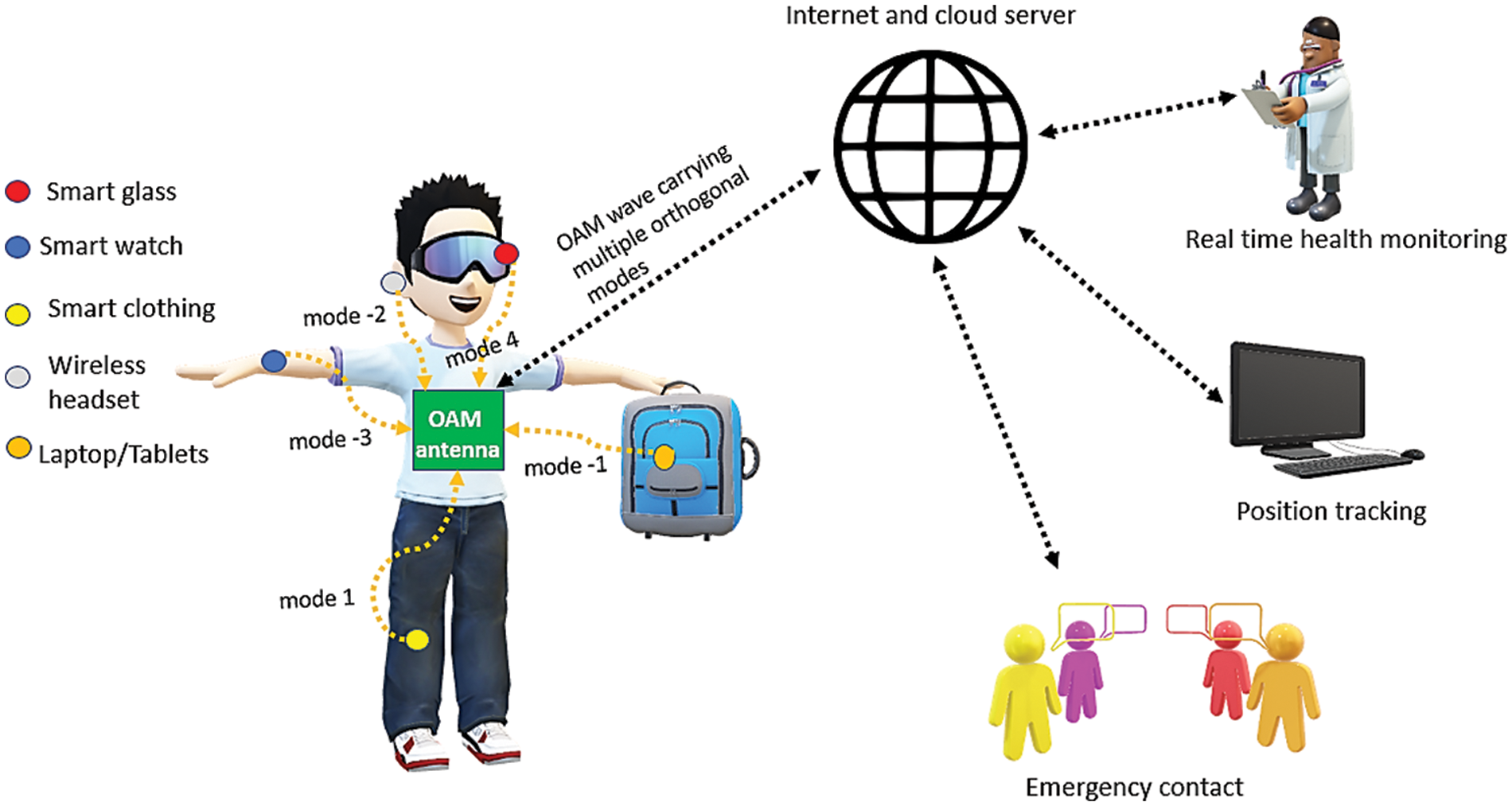
Figure 1: Potential various wearables devices assigned to various modes for body-centric communications
To practically increase the spectrum efficiency, it is important to increase the number of available OAM modes, and that is why we need to look for higher-order modes such as ±2, ±3, ±4, and so on. The difference between positive and negative OAM modes is the direction of phase distribution. OAM waves with positive mode value determines clockwise phase distribution while negative OAM mode value determines anti-clockwise phase distribution. However, the antenna design becomes more complex and challenging as the OAM mode value increases. Previous works on OAM waves using UCA involved the usage of conventional rigid substrates [12–17]. For their practical use in wearable devices, rigid and bulky antennas are not preferred. In addition, most previous research mainly designed OAM-based antennas to operate outside the 5G NR bands. The authors in [12] designed an OAM-based antenna using a rigid FR-4 substrate to generate Mode +1. A dual port OAM-based antenna using two substrates, FR-4 and Rogers 5880, was proposed to generate OAM waves from 4 to 6 GHz [13]. Moving to a Global Position System (GPS) band of 1.550 GHz, a ceramic substrate with a permittivity of 21.4 and thickness value of 4 mm was used to generate OAM mode −1 [14]. To generate two different OAM modes, a dual port FR-4-based UCA antenna was designed by [15] to operate from 5.37 to 5.69 GHz. Similarly, another FR-4 substrate-based antenna successfully generated OAM Mode −1 [16]. The authors proposed a multimode antenna in [17] using a rigid FR-4 substrate with a thickness value of 1 mm. Both OAM Modes +1 and +2 were successfully generated to operate from 2.26 to 2.35 GHz. As reported in [18], the authors developed an array antenna using Rogers 4003C as the substrate to generate two different OAM modes at 2.45 GHz. A multi-layer array antenna composed of Rogers 3010 substrate and Rogers 4003 substrate generates +1 and −1 OAM mode at 2.5 GHz. Note that the obtained gain was 5.3 dBi [19]. The authors in [20] reported that the antenna’s gain decreases as the OAM mode order increases. In regards to flexible antenna for 5G sub-6 GHz bands, the authors in [21] designed and simulated a reconfigurable antenna to operate at four different frequency bands. The gain obtained at 2.45, 3.85 and 3.2 GHz was 1.8, 2.9 and 2.78 dBi respectively. In [22], a four element patch array textile antenna was developed to operate at 2.45 GHz. The substrate used was neoprene fabric with permittivity value of 1.5, thickness value of 4 mm and the overall dimension was 110 mm × 110 mm. The measured gain at 2.56 GHz was 5.96 dBi with 4.6% impedance bandwidth. Felt textile substrate based four element array antenna was designed and simulated to operate at sub-6 GHz 5G band by the authors in [23] to generate OAM wave with mode +1. The overall antenna dimension was 156.5 mm × 170 mm. The antenna achieve very narrow bandwidth of 81.7 MHz with overall gain of 2.83 dBi. However, the measured results nor the effect of bending on OAM wave characteristic were reported by the authors. To the best of our knowledge, the effect of textile properties and bending on OAM mode purity as well as higher-order OAM mode-based antenna for body-centric wireless communications is not reported in any of the previously published works.
To fill the research gap mentioned above, this paper proposes a low-profile textile wearable antenna that can generate OAM waves with a mode value of +2. This paper presents a higher-order OAM mode, such as +2, using a flexible textile antenna for the first time. Apart from that, a prototype was fabricated to validate the working of the proposed antenna. The generated OAM wave was verified by observing a spiral phase distribution and a central null in its radiation pattern and evaluating its mode purity. The effect of bending on the OAM mode purity was also analyzed in this paper. A precise method (Hugo Voxel) to examine the effect of OAM-based antenna on human tissue was computationally analyzed for the first time. The Hugo Voxel model is more precise on the commercial electromagnetic solver, Computer Simulation Tool (CST) Microwave Studio simulation software than manually modelling the human phantom model using rectangular or cylindrical shapes. Lastly, a parametric study of the effect of textile properties such as relative permittivity, loss tangent, and thickness on ideal OAM waves-based antenna was also conducted. This paper is organized as follows. The design of the proposed antenna is first discussed in Section 2. Subsequently, the reflection coefficient, bandwidth, radiation pattern, phase distribution, intensity distribution, mode purity, and Specific Absorption Rate (SAR) are discussed in Section 3. Section 4 presents a parametric study on the effect of textile properties on the OAM mode purity. Finally, conclusions are drawn in Section 5.
2 Design of Wearable OAM Antenna Array
This paper’s proposed textile array antenna is based on a uniform circular array of microstrip patch antennas. A Shieldit super electro-textile with a 0.17 mm thickness and an estimated conductivity (σ) of 1.18 × 10⁵ Sm−1 was used as the radiating patches, feeding network, and ground plane. Other than that, the substrate used in this design was Felt textile with a relative permittivity value of 1.44, a thickness of 3 mm, and a loss tangent of 0.044. The proposed antenna was designed based on the concept explained in [16]. This paper aims to generate Orbital Angular Momentum (OAM) Mode +2. Thus, the phase difference between the two adjacent elements has to be 90°. In addition, the power received by each element has to be the same. After careful calculation and optimization, the finalized simulated textile array antenna to generate OAM Mode +2 is shown in Figs. 2a and 2b. The finalized dimensions are as follows (unit in mm): Wp = 35.4, Lp = 35.7, Wg = 250, Lg = 260, Win = 5.65, Lin = 10 and radius (r) = 106.8 mm. In this design, patches 5, 6, 7, and 8 are in the opposite orientation of patches 4, 3, 2, and 1. Moreover, the feeding network for patches 5, 6, 7, and 8 are identical to the feeding networks for patches 1, 2, 3, and 4 but in 180° clockwise rotation with an additional 180° phase difference. The obtained phase value and power (amplitude) value of each patch is demonstrated in Figs. 2c and 2d, correspondingly.
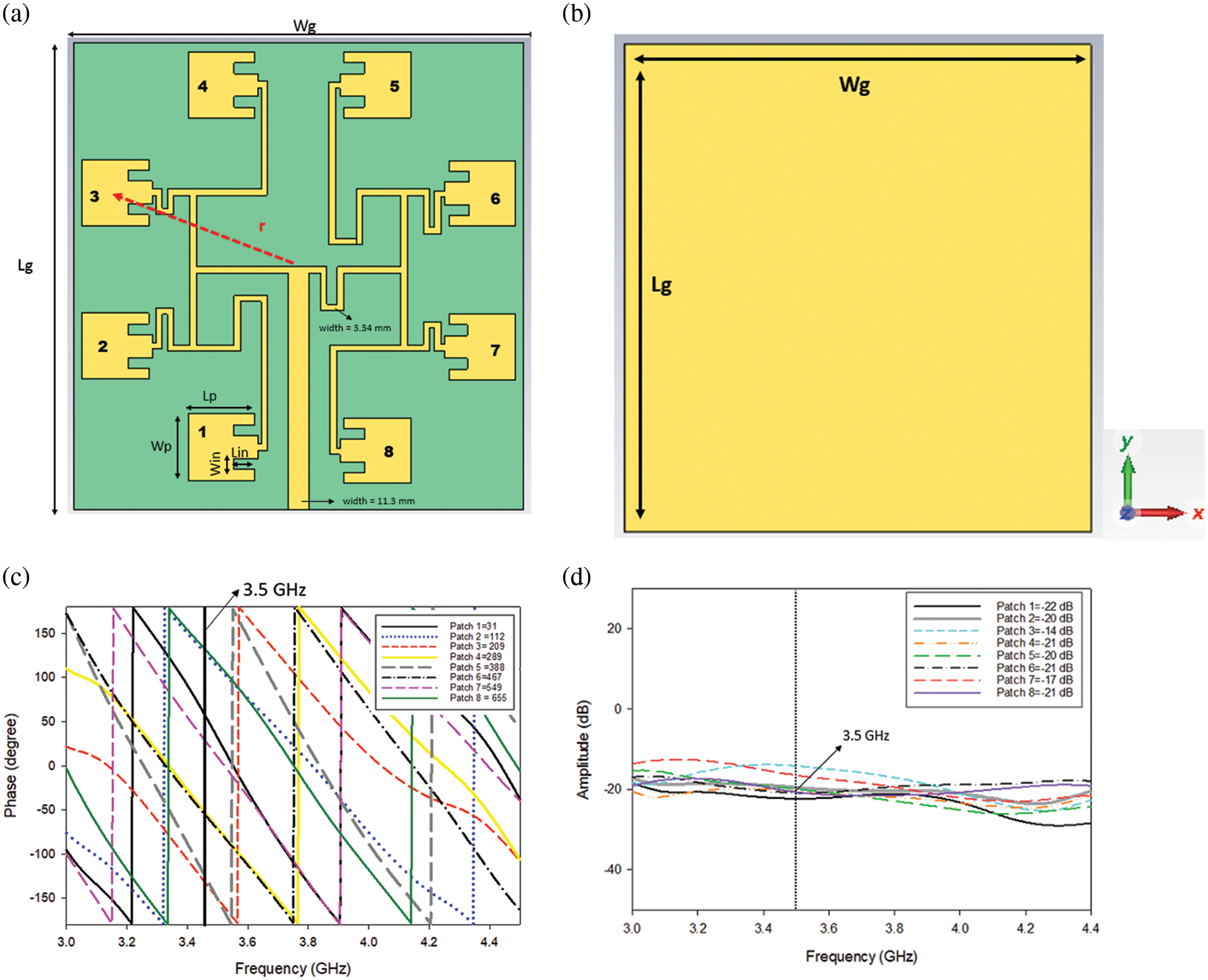
Figure 2: Proposed antenna (a) Simulated front view (b) Simulated back view (c) Simulated phase(d) Simulated amplitude
The fabrication process of the proposed antenna is summarized in Fig. 3. At first, the structure of the proposed antenna with the exact dimension from the simulation was printed on a piece of paper, serving as the guideline for cutting the super-Shieldit electro-textile. In this step, Gerber software was used. Another advantage of printing the structure with the correct dimension is to prevent the radiating patches and feedline from deforming or shifting while attaching them to the substrate. Consequently, the printed paper was tightly secured on super-Shieldit textile and was manually cut with a cutter and scissors. Next, the substrate was cut per the simulated design dimension, and the patches and feedlines were carefully placed on top of the substrate. To excite the antenna, a 50 Ω female SubMiniature version A (SMA) connector was soldered onto the feedline. Lastly, a multimeter was used to check the continuity between the SMA connector inner pin and the feedline.
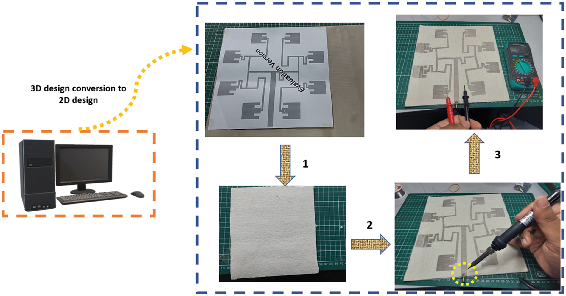
Figure 3: Fabrication process of the proposed antenna
3 Experimental Setup, Results, and Discussions
This section presents the simulated and Measured results for the proposed antenna. First, the simulations and measurements for the reflection coefficient were carried out to verify that the proposed antenna works at the desired frequency under different conditions. Second, computational-based studies were performed to confirm Orbital Angular Momentum (OAM) Mode +2 by analyzing the phase distribution, intensity distribution (vortex core), null in the boresight direction (2D polar form), and mode purity, as shown in Fig. 4.
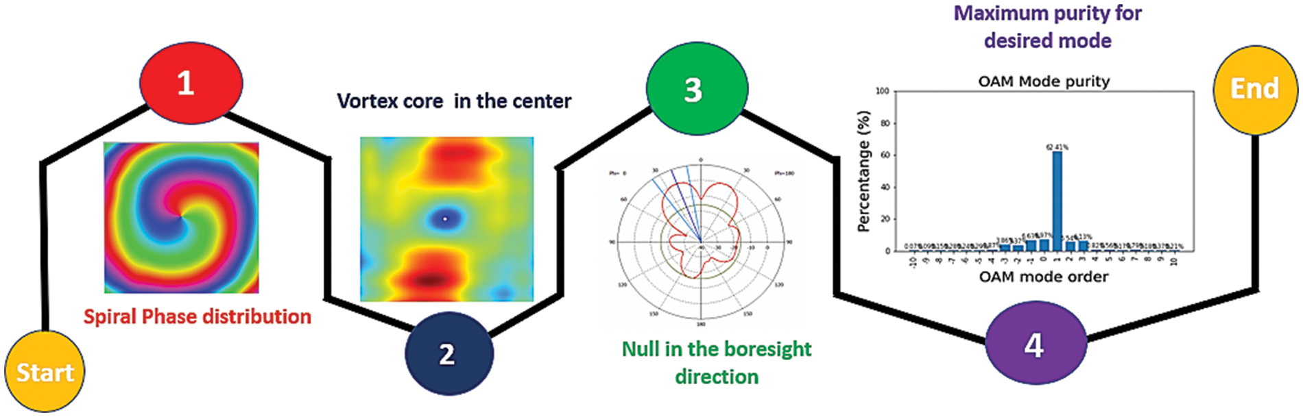
Figure 4: Four parameters to confirm the generation of OAM waves
3.1 Reflection Coefficient (S11) and Bandwidth
The setup for the proposed design’s reflection coefficient and bandwidth measurement is shown in Fig. 5a. The proposed design’s simulated −10 dB impedance bandwidth covered 2.772 to 4.19 GHz, as shown in Fig. 5b for free space flat and 5° bending. Note that the simulated antenna resonated at 3.5 GHz with an S11 value of −19.67 dB for flat conditions and −20.32 dB for bending conditions. As shown in Fig. 5b, at 3.5 GHz, the fabricated antenna achieved an S11 value of −10.08 dB during free space flat condition, −10.42 dB for the on-body condition, and −17.5 dB during 5° bending. Furthermore, the bandwidth is from 3.48 to 3.88 GHz, 3.5 to 3.86 GHz, and 3.44 to 3.70 GHz for free space flat, on-body flat, and 5° bending conditions, respectively. Some differences between the simulated and measured results can be attributed to the fabrication error, especially the radiating elements dimension. Along with the fabrication error, the shift in frequency could be due to the impedance mismatch of the radiating elements with the phase divider feeding network. The fabricated antenna covered the fifth-generation (5G) New Radio (NR) bands, which include n78 (3.3 to 3.8 GHz) and n77 (3.3 to 4.2 GHz). Hence, the measured reflection coefficient justified that the proposed antenna is well-accepted as a wearable antenna.
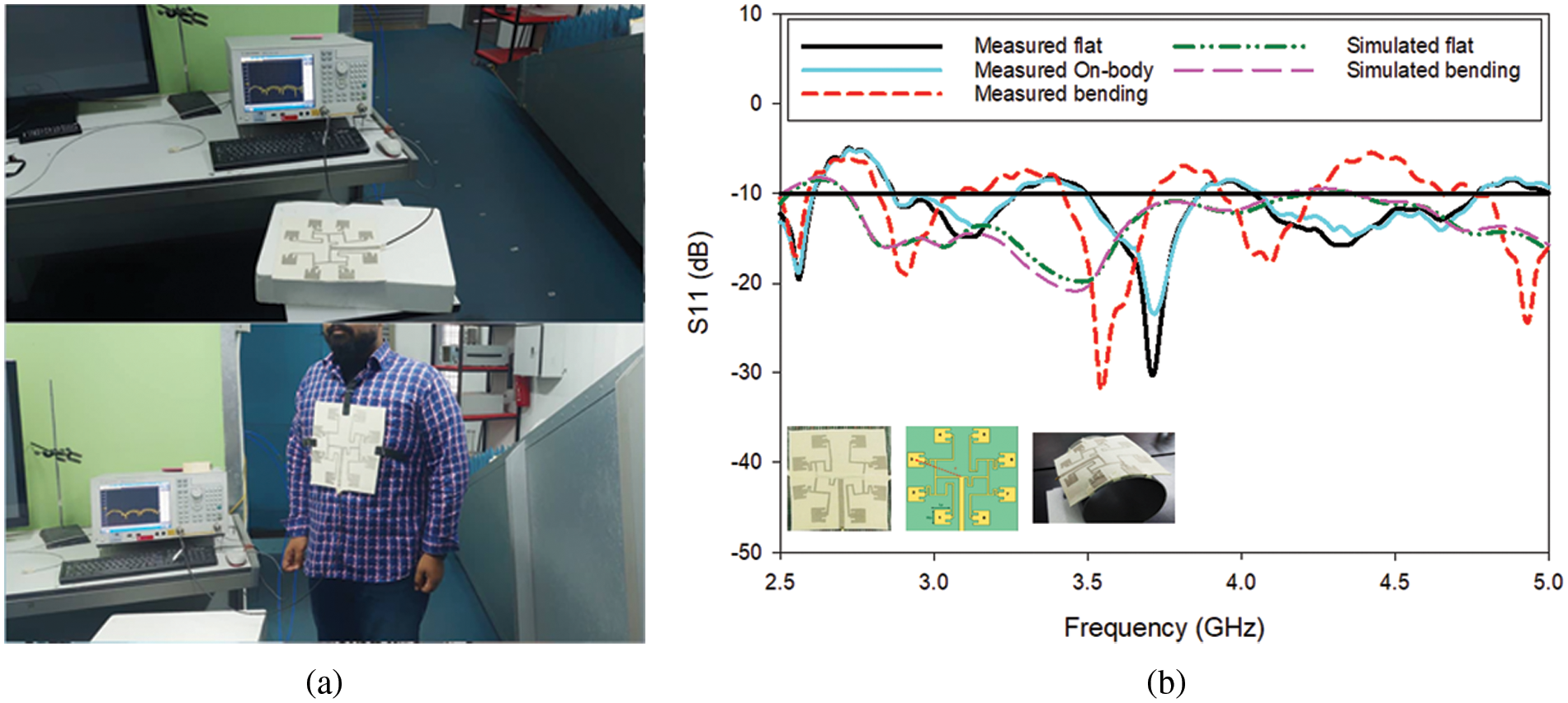
Figure 5: S11 and bandwidth measurement (a) Measurement setup (b) Simulated and measured results
3.2 Phase and Intensity Distribution
In order to verify the generation of OAM Mode +2 with the proposed textile wearable antenna, the phase distribution was first simulated on a transverse observation plane with a radius of 400 mm, located 400 mm away from the antenna. Fig. 6a shows the simulated phase distribution of the antenna, illustrating that the proposed antenna exhibits a spiral phase distribution with a continuous phase change around the center, which is a characteristic feature of an OAM wave [24]. Other than that, a vortex core around the center of the intensity distribution in Fig. 6b is seen, a characteristic of OAM waves [25]. When the antenna was bent to 5°, the phase distribution and intensity distribution patterns were distorted, as shown in Figs. 6c and 6d, respectively.
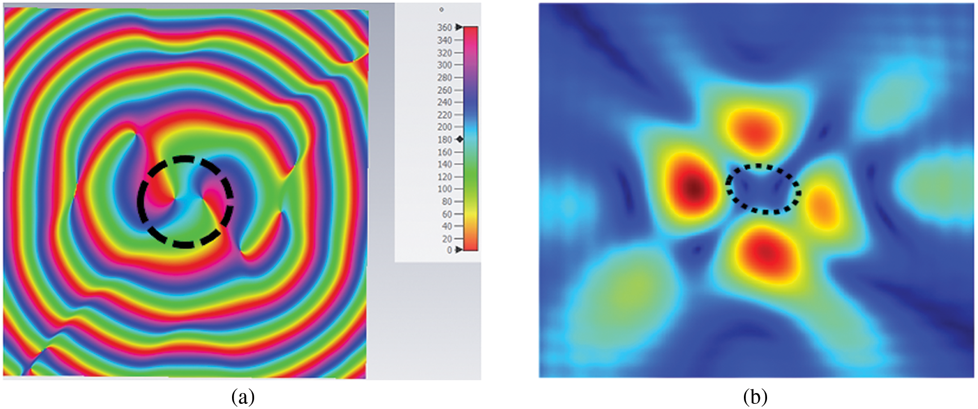
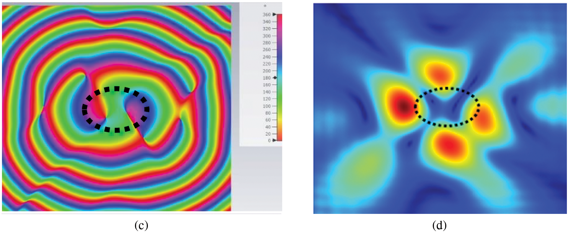
Figure 6: Simulated phase and intensity distribution (a) Phase distribution for flat condition(b) Intensity distribution for flat condition (c) Phase distribution at 5° bending (d) Intensity distribution at 5° bending
The setup for measuring the radiation pattern in E-plane at xz direction inside an Anechoic chamber is illustrated in Fig. 7a. As reported in [26], an intensity null at the center in the boresight direction is a characteristic of OAM waves, which is apparent in the plot as shown in Fig. 7b for the simulated and measured results at 5G n77 and n78 bands. Moreover, the simulated gain obtained was 2.018 dBi at 3.5 GHz, as shown in Fig. 7c for free space flat and 1.816 dBi for 5° free space bending in Fig. 7d. Since the radiating patch orientations were opposite, and there was a center null, the gain is smaller despite using eight radiating elements. Nonetheless, the obtained gain was fairly moderate because textile substrates are highly lossy compared to conventional rigid substrates.
Figure 7: Radiation pattern results (a) Measurement setup (b) Simulated and measured 2D polar form (c) Simulated gain for free space flat condition (d) Simulated gain for free space 5° bending
3.4 Surface Current Distribution
The surface current distribution on the proposed antenna at different phase instants at 3.5 GHz is shown in Fig. 8. The purpose of analyzing the surface current distribution on an antenna is to detect the regions on the antenna where the maximum flow of current is taking place. Apart from that, this region can be modified to make some changes in the antenna design or to alter certain parameters. It can be observed that the surface current distribution maximum value at 3.5 GHz was 23.26 A/m. Moreover, the surface current distribution at phases 0° and 180° are similar, as shown in Figs. 8a and 8c. At phases 90° and 270°, as shown in Figs. 8b and 8d, the surface current is identical. When the phases are 0° and 180°, the surface current is strong and identical at the feeds of patches 1, 3, 5, and 7, while at phases 90° and 270°, the surface current is strong and identical at the feeds of patches 2, 4, 6 and 8. Besides, a 90° successive phase delay is also observed between the adjacent elements, contributing to the generation of OAM waves with Mode ±2 using eight radiating elements [24]. The current flows along the vertical line (Y-direction) from the excitation port and horizontally (X-direction) towards radiating patches. In both cases, the current distribution is concentrated along the radiating patches’ edges and slot (inset feed).
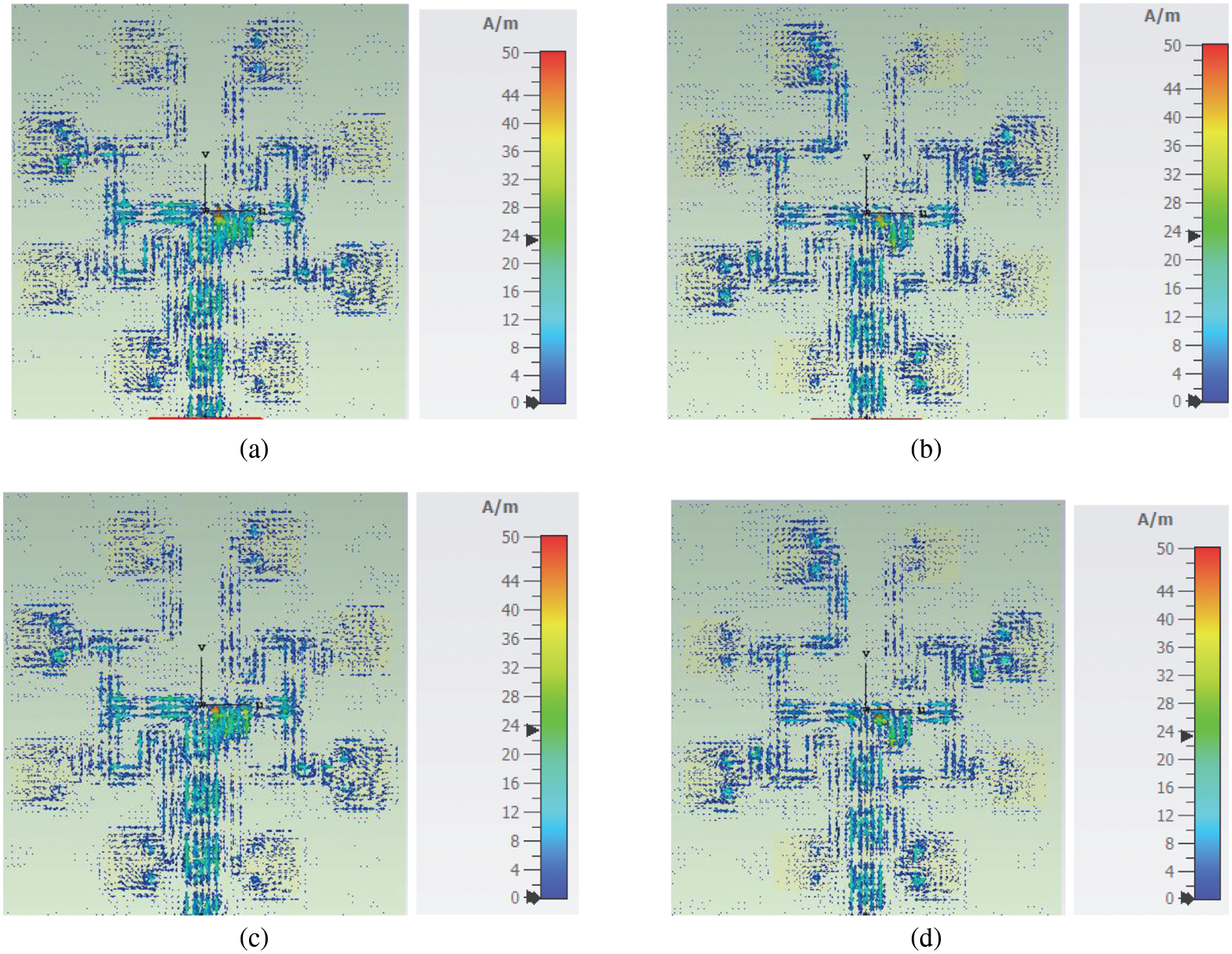
Figure 8: Simulated surface current distribution (a) Phase = 0° (b) Phase = 90° (c) Phase = 180°(d) Phase = 270°
To quantitatively evaluate the purity of the OAM mode generated by the proposed textile antenna, we performed an analysis using Fourier analysis [27]. The mode purity of an OAM wave is defined as the percentage of power in the dominant mode to the total power of the wave. Fig. 9 shows the results of the mode purity analysis for the flat and 5° bending cases. It can be seen that, for both cases, the purity is significantly higher in the desired mode, which is Mode +2, with the bending case having a slightly lower purity than the flat case. It can therefore be concluded that the proposed antenna can generate the intended OAM Mode +2.
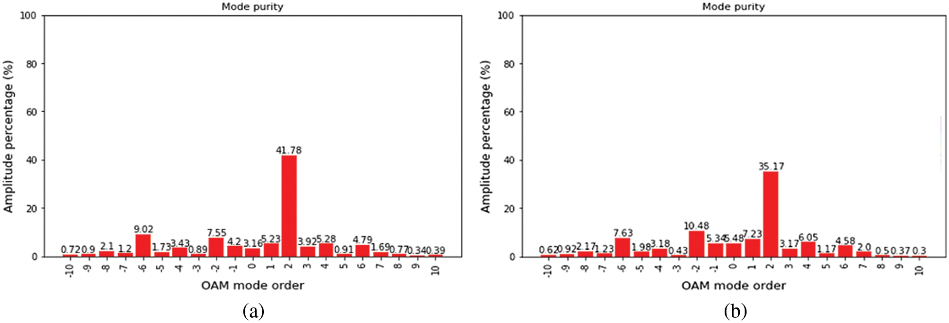
Figure 9: Mode purity of OAM +2 mode (a) Free space flat condition (b) Free space 5° bending
3.6 Specific Absorption Rate (SAR)
For practical implementation of the proposed antenna for wearable and body-centric communication systems, it is important to verify that the antenna is safe to be mounted on the human body. Thus, the Specific Absorption Rate (SAR) is performed. The perspective view of the placement of the proposed antenna is shown in Fig. 10a. In addition, the human Hugo voxel model is modeled using CST 2022 software to analyze the radiation effect of the proposed antenna on the human body. The SAR value obtained for average 1 g tissue was 0.00337 W/kg, and 10 g tissue was 0.0017 W/kg, as shown in Figs. 10b and 10c, respectively. Hence, the proposed antenna is safe for body-centric communications as per the specification set by Federal Communication Commission (FCC) and The International Commission on Non-Ionizing Radiation Protection (ICNIRP) [28].
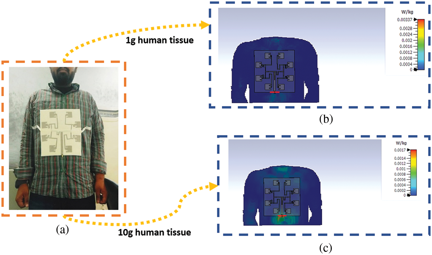
Figure 10: Specific abortion rate (a) Proposed potential antenna placement on the human body (b)1 g tissue (c) 10 g tissue
4 Parametric Analysis of Textile Properties Influence on Ideal OAM-Based UCA Antenna
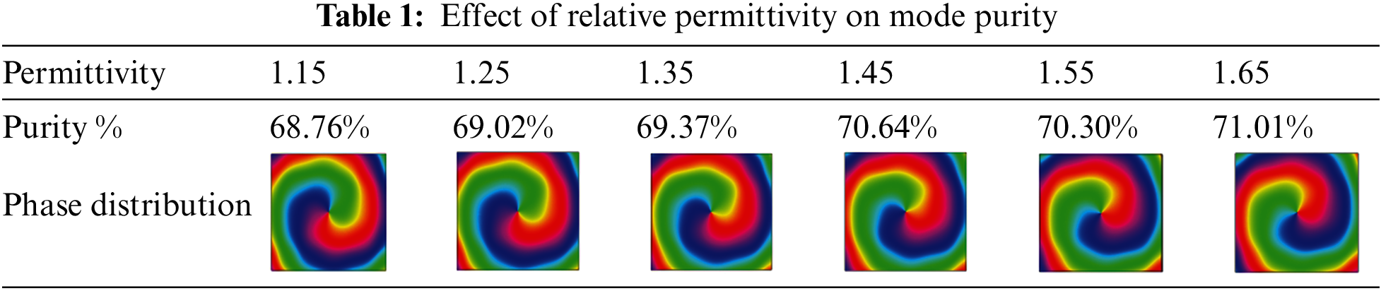
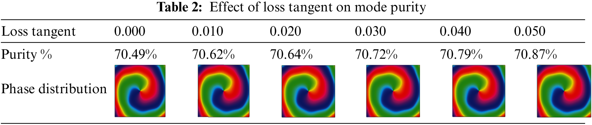
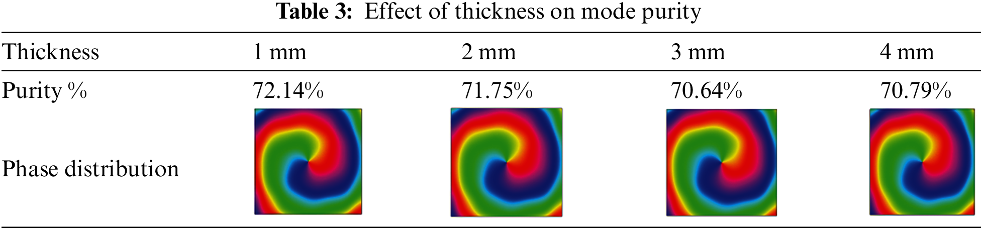
Textile properties such as relative permittivity, loss tangent, and thickness significantly influence antenna performances, such as bandwidth, gain, and efficiency [29]. The mode purity parameter is crucial for OAM-based antennae to maintain it’s orthogonality. In general, lower relative permittivity results in improved impedance bandwidth due to lower surface waves losses [30]. Next, thickness has major influence for the matching of the radiating elements with feedline [31]. The antenna tends to have wider bandwidth if thicker substrate is used. Lastly, loss tangent determines antennas gain and efficiency. If the loss tangent value is higher, antenna tends to achiever lower gain and efficiency [32]. This sub-section analyzes the effect of textile properties on OAM mode purity. The substrate used for this analysis is Felt fabric with relative permittivity of 1.44, loss tangent of 0.044, and thickness value of 3 mm. This analysis uses an ideal Uniform Circular Array (UCA) of four microstrip patches, where the patches are individually excited by separate ports instead of using a common feed network. Note that the phases of the ports were manually set so that any two adjacent patches had a phase difference of 90°. After the UCA was designed and simulated, the substrate properties were varied, as illustrated in Fig. 11.
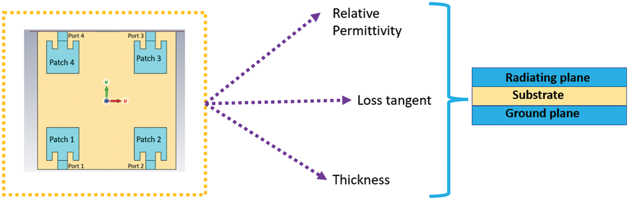
Figure 11: Parametric study of the influence of textile properties on OAM mode purity
From Table 1, it can be observed that as the relative permittivity value increases, the purity increases slightly. As the relative permittivity, the phase distribution maintained their OAM characteristics. From Table 2, it can be observed that as the loss tangent value increases, the purity tends to increase slightly. While varying the loss tangent, the phase distribution maintained the OAM characteristics. As shown in Table 3, the purity tends to reduce slightly as the thickness value increases. From the obtained result, it can be seen that the textile properties have a minor influence on the mode purity.
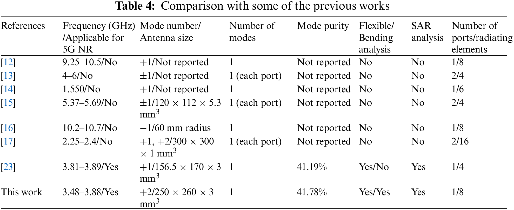
The proposed antenna is compared with some of the previously published works on generating OAM waves using a UCA, and the comprehensive comparison is tabulated in Table 4. The proposed antenna is suitable for OAM waves-based body-centric communications at 5G NR bands compared to other works.
A textile wearable antenna that can generate higher-order Orbital Angular Momentum (OAM) waves, such as OAM Mode ±2, is designed for the very first time for body-centric communications. The generation of OAM wave using textile fabric was confirmed by the computational results obtained from phase distribution, intensity distribution, the 2D radiation pattern, and mode purity. Other than that, the actual measurement of the proposed antenna’s radiation pattern is carried out, and a null in the boresight direction is observed. The proposed fabricated antenna achieved overall bandwidth of 400 MHz for potential applications in fifth-generation (5G) New Radio (NR) n77 and n78 bands. This work shall assist future researchers in developing higher-order OAM modes such as ±3, ±4, and reduction in overall array size in the wearable communication domain. Additionally, the critical parameters of the introduced textile antenna design, such as mode purity, bending analysis, and Specific Absorption Rate (SAR) analysis, have been investigated, and quite promising results have been observed. Based on the obtained SAR results, the proposed antenna is suitable for future OAM waves-based communication in the wearable domain.
Funding Statement: This work was supported by Ministry of Higher Education through the Fundamental Research Grant Scheme (FRGS) under a grant number of FRGS/1/2020/ICT09/UNIMAP/ 02/2.
Conflicts of Interest: The authors declare that they have no conflicts of interest to report regarding the present study.
References
1. R. Chataut and R. Akl, “Massive MIMO systems for 5G and beyond networks—Overview, recent trends, challenges, and future research direction,” Sensors, vol. 20, no. 10, pp. 1–35, 2020. [Google Scholar]
2. S. S. Al-Bawri, M. T. Islam, M. J. Singh, E. Alyan, M. Jusoh et al., “Broadband sub-6 GHz slot-based mimo antenna for 5g nr bands mobile applications,” Journal of Physics: Conference Series, vol. 1962, no. 1, pp. 1–7, 2021. [Google Scholar]
3. J. Iqbal, U. Illahi, M. N. M. Yasin, M. A. Albreem and M. F. Akbar, “Bandwidth enhancement by using parasitic patch on dielectric resonator antenna for sub-6 GHz 5G NR bands application,” Alexandria Engineering Journal, vol. 61, no. 6, pp. 5021–5032, 2022. [Google Scholar]
4. Spectrum for 4G and 5G, Qualcomm Technologies Inc, 2020. [Online]. Available: https://www.qualcomm.com/media/documents/files/spectrum-for-4g-and-5g.pdf (Accessed Nov. 22, 2022). [Google Scholar]
5. H. Askari, N. Hussain, D. Choi, M. Abu Sufian, A. Abbas et al., “An amc-based circularly polarized antenna for 5G sub-6 Ghz communications,” Computers, Materials & Continua, vol. 69, no. 3, pp. 2997–3013, 2021. [Google Scholar]
6. M. A. Sufian, N. Hussain, H. Askari, S. G. Park, K. S. Shin et al., “Isolation enhancement of a metasurface-based mimo Antenna using slots and shorting pins,” IEEE Access, vol. 9, pp. 73533–73543, 2021. [Google Scholar]
7. Y. Yan, G. Xie, M. P. J. Lavery, H. Huang, N. Ahmed et al., “High-capacity millimetre-wave communications with orbital angular momentum multiplexing,” Nature Communications, vol. 5, no. 4876, pp. 1–9, 2014. [Google Scholar]
8. H. Liuli, “Is OAM a better transmission method than MIMO scheme?,” in Proc. 5th Int. Conf. Communication, Image Signal Process. (CCISP), Chengdu, China, pp. 10–14, 2020. [Google Scholar]
9. H. Jing, W. Cheng, X. -G. Xia and H. Zhang, “Orbital-angular-momentum versus MIMO: Orthogonality, degree of freedom, and capacity,” in Proc. IEEE 29th Annu. Int. Symp. Pers., Indoor Mobile Radio Commun. (PIMRC), Bologna, Italy, pp. 1–7, 2018. [Google Scholar]
10. L. Wang, F. Jiang, Z. Yuan, J. Yang, G. Gui et al., “Mode division multiple access: A new scheme based on orbital angular momentum in millimetre wave communications for fifth generation,” IET Communications, vol. 12, no. 12, pp. 1416–1421, 2018. [Google Scholar]
11. S. K. Noor, M. N. M. Yasin, A. M. Ismail, M. N. Osman, P. J. Soh et al., “A review of orbital angular momentum vortex waves for the next generation wireless communications,” IEEE Access, vol. 10, no. August, pp. 89465–89484, 2022. [Google Scholar]
12. S. Singh, M. D. Upadhayay and S. Pal, “Study on generation of higher order orbital angular momentum modes and parameters affecting the vortex,” Iranian Journal of Electrical and Electronic Engineering, vol. 17, no. 2, pp. 1–10, 2021. [Google Scholar]
13. C. Zhou, W. Yang, Q. Xue and W. Che, “Low-profile wideband dual-circularly polarized orbital angular momentum antenna array using metasurface,” Microwave and Optical Technology Letters, vol. 63, no. 4, pp. 1207–1212, 2021. [Google Scholar]
14. K. Bi, J. Xu, D. Yang, Y. Hao, X. Gao et al., “Generation of orbital angular momentum beam with circular polarization ceramic antenna array,” IEEE Photonics Journal, vol. 11, no. 2, pp. 1–8, 2019. [Google Scholar]
15. H. Li, L. Kang, F. Wei, Y. M. Cai and Y. Z. Yin, “A low-profile dual-polarized microstrip antenna array for dual-mode oam applications,” IEEE Antennas and Wireless Propagation Letters, vol. 16, pp. 3022–3025, 2017. [Google Scholar]
16. Q. Bai, A. Tennant and B. Allen, “Experimental circular phased array for generating OAM radio beams,” Electronics Letters, vol. 50, no. 20, pp. 1414–1415, 2014. [Google Scholar]
17. D. Liu, L. Gui, Z. Zhang, H. Chen, G. Song et al., “Multiplexed oam wave communication with two-oam-mode antenna systems,” IEEE Access, vol. 7, pp. 4160–4166, 2019. [Google Scholar]
18. H. Naseri, P. PourMohammadi, N. Melouki, A. Iqbal and T. A. Denidni, “A low-profile antenna system for generating reconfigurable oam-carrying beams,” IEEE Antennas and Wireless Propagation Letters, pp. 402–406, 2022. [Google Scholar]
19. Q. Liu, Z. N. Chen, Y. Liu, F. Li, Y. Chen et al., “Circular polarization and mode reconfigurable wideband orbital angular momentum patch array antenna,” IEEE Transactions on Antennas and Propagation, vol. 66, no. 4, pp. 1796–1804, 2018. [Google Scholar]
20. W. Cheng, W. Zhang, H. Jing, S. Gao and H. Zhang, “Orbital angular momentum for wireless communications,” IEEE Wireless Communications, vol. 26, no. 1, pp. 100–107, 2019. [Google Scholar]
21. M. Hussain, S. N. R. Rizvi, W. A. Awan, N. Husain, Halima et al., “On-demand frequency reconfigurable flexible antenna for 5Gsub-6-GHz and ism band applications,” Lecture Notes in Electrical Engineering, vol. 745, pp. 1085–1092, 2020. [Google Scholar]
22. Chin, Kuo-Sheng, Wu, Chi-Sheng, Shen et al., “Designs of textile antenna arrays for smart clothing applications,” Autex Research Journal, vol. 18, no. 3, pp. 295–307, 2018. [Google Scholar]
23. S. K. Noor, A. M. Ismail, M. N. Mohd Yasin, M. N. Osman and N. Ramli, “Orbital angular momentum vortex waves generation using textile antenna array for 5g wearable applications,” in IEEE Symp. on Wireless Technology & Applications (ISWTA), Selangor, Malaysia, pp. 7–12, 2022. [Google Scholar]
24. H. Li, L. Kang and K. Dong, “Generating tunable orbital angular momentum radio beams with dual-circular-polarization and dual-mode characteristics,” IEEE Access, vol. 8, pp. 211248–211254, 2020. [Google Scholar]
25. W. Lee, J. Y. Hong, M. S. Kang, B. S. Kim, K. S. Kim et al., “Microwave orbital angular momentum mode generation and multiplexing using a waveguide butler matrix,” ETRI Journal, vol. 39, no. 3, pp. 336–344, 2017. [Google Scholar]
26. L. Fang, H. Yao and R. Henderson, “Design and performance of OAM modes generated using dipole arrays with different feeds,” in Proc. IEEE Radio and Wireless Symp. (RWS), Anaheim, CA, USA, vol. 2018-Janua, pp. 200–202, 2018. [Google Scholar]
27. Y. Huang, X. Li, Q. Li, Z. Qi, H. Zhu et al., “Generation of broadband high-purity dual-mode oam beams using a four-feed patch antenna: Theory and implementation,” Scientific Reports, vol. 9, no. 1, pp. 1–10, 2019. [Google Scholar]
28. N. A. Shamsudin and S. M. Shah, “Miniaturized dual-band dual-mode microstrip patch antenna with defected ground structure for wearable applications,” Journal of Electronic Voltage and Application, vol. 2, no. 2, pp. 120–128, 2021. [Google Scholar]
29. A. W. Memon, I. L. de Paula, B. Malengier, S. Vasile, P. V. Torre et al., “Breathable textile rectangular ring microstrip patch antenna at 2.45 GHz for wearable applications,” Sensors, vol. 21, no. 5, pp. 1635, 2021. [Google Scholar] [PubMed]
30. M. M. Khan, B. Y. Akowuah, K. Islam, E. T. Tchao, S. Bhattacharyya et al., “Novel design of uwb jeans based textile antenna for body-centric communications,” Computer Systems Science and Engineering, vol. 42, no. 3, pp. 1079–1093, 2022. [Google Scholar]
31. S. Parameswari and C. Chitra, “Compact textile UWB antenna with hexagonal for biomedical communication,” Journal of Ambient Intelligence and Humanized Computing, vol. 62, no. 1, pp. 102, 2021. [Google Scholar]
32. M. S. A. Nordin, N. H. A. Rahman, M. T. Ali, N. I. Zaidi and M. R. Ahmad, “Analysis on wearable antenna performance on different radiating elements for gps application,” International Journal of Integrated Engineering, vol. 12, no. 6, pp. 40–48, 2020. [Google Scholar]
Cite This Article
 Copyright © 2023 The Author(s). Published by Tech Science Press.
This work is licensed under a Creative Commons Attribution 4.0 International License , which permits unrestricted use, distribution, and reproduction in any medium, provided the original work is properly cited.
 Downloads
 Citation Tools