
 Submit a Paper
 Propose a Special lssue
 Open Access
ARTICLE

A Feasibility Study of Using Geothermal Energy to Enhance Natural Gas Production from Offshore Gas Hydrate Reservoirs by CO2 Swapping
Department of Petroleum Engineering, University of Louisiana at Lafayette, Lafayette, 70504, USA
* Corresponding Author: Md Nahin Mahmood. Email:
Energy Engineering 2023, 120(12), 2707-2720. https://doi.org/10.32604/ee.2023.042996
Received 19 June 2023; Accepted 18 September 2023; Issue published 29 November 2023
 View Full Text
 Download PDF
Abstract
The energy industry faces a significant challenge in extracting natural gas from offshore natural gas hydrate (NGH) reservoirs, primarily due to the low productivity of wells and the high operational costs involved. The present study offers an assessment of the feasibility of utilizing geothermal energy to augment the production of natural gas from offshore gas hydrate reservoirs through the implementation of the methane-CO2 swapping technique. The present study expands the research scope of the authors beyond their previous publication, which exclusively examined the generation of methane from marine gas hydrates. Specifically, the current investigation explores the feasibility of utilizing the void spaces created by the extracted methane in the hydrate reservoir for carbon dioxide storage. Analytical models were employed to forecast the heat transfer from a geothermal zone to an NGH reservoir. A study was conducted utilizing data obtained from a reservoir situated in the Shenhu region of the Northern South China Sea. The findings of the model indicate that the implementation of geothermal heating can lead to a substantial enhancement in the productivity of wells located in heated reservoirs during CO2 swapping procedures. The non-linear relationship between the temperature of the heated reservoir and the rate of fold increase has been observed. It is anticipated that the fold of increase will surpass 5 when the gas hydrate reservoir undergoes a temperature rise from 6°C to 16°C. The mathematical models utilized in this study did not incorporate the impact of heat convection resulting from CO2 flow into the gas reservoir. This factor has the potential to enhance well productivity. The mathematical models’ deviation assumptions may cause over-prediction of well productivity in geothermal-stimulated reservoirs. Additional research is required to examine the impacts of temperature drawdown, heat convection resulting from depressurization, heat-induced gas pressure increment, and the presence of free gas in the formation containing hydrates. The process of CH4-CO2 swapping, which has been investigated, involves the utilization of geothermal stimulation. This method is highly encouraging as it enables the efficient injection of CO2 into gas hydrate reservoirs, resulting in the permanent sequestration of CO2 in a solid state. Additional research is warranted to examine the rate of mass transfer of CO2 within reservoirs of gas hydrates.Keywords
Nomenclature
| Specific heat of reservoir rock, J/kg-°C | |
| Heat capacity of the fluid inside the wellbore, J/kg-°C | |
| Inner diameter of insulation-cement sheath, ft | |
| Inner diameter of pipe, ft | |
| Outer diameter of insulation-cement sheath, ft | |
| Outer diameter of pipe, ft | |
| Non-darcy coefficient in day/Mscf | |
| Geothermal gradient, °C/ft | |
| H | Reservoir thickness, ft |
| Anisotropy index | |
| Horizontal permeability, mD | |
| Vertical permeability, mD | |
| Thermal conductivity of the insulation-cement, W/(m.°C) | |
| Thermal conductivity of insulation pipe, W/(m.°C) | |
| Length of the horizontal well, ft | |
| Fluid flow rate, m3/S | |
| Reservoir pressure, psia | |
| Wellbore flowing pressure, psia | |
| Well production rate, Mscf/day | |
| Fluid circulation rate, m3/s | |
| Wellbore radius of laterals, ft | |
| Radius of drainage area, ft | |
| Skin factor | |
| Thickness of cement sheath, ft | |
| Reservoir temperature, °C | |
| Initial reservoir temperature, °C | |
| Temperature of the injected fluid, °C | |
| Inlet temperature, °C | |
| Geothermal temperature at the top of the vertical section, °C | |
| Outlet temperature, °C | |
| Density of reservoir rock, kg/m3 | |
| Density of the injected fluid, kg/m3 | |
| Gas specific gravity |
Methane gas hydrates are formed through the crystallization of ice and methane. Water molecules enclose methane molecules. Depressurization and heat decompose methane hydrate into natural gas and water. Offshore methane hydrate (fire ice) reserves exist worldwide. Organic-rich silt, permafrost, and marine subsurface produce methane hydrates. Scholarly sources believe this resource outnumbers all other fossil fuels [1]. According to Dawe et al. [2], methane hydrate reservoirs have great promise as a global economy-boosting natural gas supply.
Gas hydrates form in environments like permafrost and ocean sediment. Researchers agree that microbial or thermogenic mechanisms produce extremely concentrated methane in natural hydrates [3,4]. Microbial and thermogenic processes decompose organic matter anaerobically and thermally, respectively. Literature lists four key variables that cause solid gas hydrates: water phase, hydrocarbon phase, low temperature, and high pressure [5,6]. ‘Hydrate formers’ are molecules that can exist in gaseous and liquid phases and are miscible or immiscible in water. Gas composition, salinity, temperature, and pressure affect fluid hydration [5]. Recent investigations found a large gas hydrate reservoir in the oceans. Melting a cubic meter of hydrates releases approximately 170 cubic meters of gas, according to research. This supports oil and gas corporations’ increasing interest in the production of gas hydrates [7]. However, silt formation, wellbore collapse, and low productivity make marine gas hydrate resource exploitation difficult [8]. The best ways to use this large renewable energy resource are being researched worldwide. The research includes petrophysical characteristics, reservoir geology, and field experiments [9]. Field pilot projects help researchers understand the major obstacles to commercial gas hydrate production. Generating this gaseous commodity is one of the least studied gas hydrate issues. Hydrates dissociate using three mechanisms. Depressurization, heat stimulation, thermodynamic inhibitor injection, and combinations of these are used [8,9].
The process of depressurization involves reducing the pressure of natural gas hydrates to a level below their dissociation pressure, thereby liberating natural gases that can be retrieved at the surface [10,11]. Thermal stimulation involves injecting boiling water or brine into the hydrate reservoir to increase its temperature above its dissociation temperature [12–14]. Thermodynamic inhibitor injection includes adding chemical agents like salts and alcohols to change the pressure-temperature equilibrium for hydrates [15,16]. Moridis et al. [17,18] also recorded additional technique combinations. Unfortunately, each of these methods has drawbacks that make them unreliable when used alone. Thermal hydrate dissociation is slow, expensive, and energy-intensive. The concentration, velocity, and interfacial tension of hydrates and chemical inhibitors constrain the inhibitor injection strategy [8]. Besides, salts and alcohols hinder the pressure-temperature equilibrium [19].
The most popular and cost-effective method, depressurization, produces little gas. The dissociation of natural gas hydrates consumes a lot of energy, resulting in a Joule-Thompson cooling effect and a lower hydrate temperature [8]. Kurihara et al. [20] found that secondary hydrate can occur near the producing wellbore when the temperature drops toward hydrate formation. This can obstruct flow, reducing productivity. Researchers found that heat transmission dominates natural gas hydrate dissociation [17,21,22]. Depressurization requires gradual pressure and temperature changes to sustain gas hydrate reservoir production. However, the system requires an external thermal source. Guo et al. [9,23] found that heating active hydrate reservoirs can prolong production. This study examines geothermal energy as a sustainable method for depressurization, taking into consideration pertinent concerns.
Predicting a gas hydrate reservoir’s temperature is very crucial. dissociation of the hydrate and changes in ambient pressure and temperature beyond its stability zone make direct gas extraction from its hydrate form difficult [24]. Wang et al. [25] reported the results of a large-scale experimental and analytic research of heat and mass transmission during dissociation of hydrates utilizing multiple dissociation methods. Researchers observed that depressurization and thermal stimulation synergize. Heat, not depressurization, dissociates hydrates. Wang et al. [26] investigated depressurization-induced methane hydrate dissociation scaling principles. The researchers found that field-scale gas production during hydrate reservoir depressurization is significant but insufficient for commercial reasons. Wang et al. [27] investigated the mechanics of fluid flow and parameters of heat transfer for gas extraction from saturated hydrate reservoirs. The researchers found that thermal stimulation assisted by depressurization is the best method for dissociating hydrates in completely saturated reservoirs.
The depressurization production scheme’s sediment production and wellbore collapse are hindering gas hydrate recovery. Gas hydrate dissociation releases gas and water and causes issues. The hydrate structure was unaffected by replacing a single CH4 molecule with a CO2 molecule [28]. Water generation and stratum collapse were modest in the above technique. Molecule exchange outcompetes other extraction methods. Carbon dioxide might be permanently trapped in the reservoir using the above approach. CO2 hydrate mass transfer obstacles reduce CH4 generation exchange efficiency [29]. This study proposes CO2 swapping, depressurization, and geothermal stimulation to solve the problem. Depressurization and heating enhance CH4-hydrate dissociation, which helps CO2 diffuse through channels.
Scientists have studied the thermodynamics and kinetics of depressurization-assisted exchange of CH4 and CO2 [30–32]. Recently a well configuration shaped like ‘Y’ has been developed along with a heat transfer model to use geothermal energy for gas hydrate reservoir development [33]. Gas hydrate deposits may be extracted by using geothermal energy transmitted to a gas hydrate reservoir. The process involves injecting water into a reservoir injection well. Geothermal energy heats it. This heated fluid elevates the temperature of the hydrate-bearing zone, causing hydrate dissociation. A secondary production well collects dissociated gases. The working fluid transfers geothermal energy to the gas hydrate zone, dissociating methane. Thermally treating gas hydrates retrieve the cooler working fluid for reinjection. Guo et al. [9] modified the mathematical model of Fu et al. [33] to predict future gas hydrate reservoir temperatures based on geothermal fluid heat transfer.
In the context of geothermal energy use, this study examines the feasibility of CH4-CO2 swapping to increase natural gas production from offshore gas hydrate reservoirs. This analysis expands on Mahmood et al.'s [34] work. The previous article focused on marine gas hydrate methane production. However, this study includes carbon dioxide sequestration in natural gas hydrate reservoirs that are empty due to methane generation. Here, the authors attempted to employ a heat transfer model in order to make projections about the future condition of a reservoir and to forecast the likelihood of increased productivity in conjunction with CO2 storage within a gas hydrate reservoir. Geothermal energy has been regarded as the primary heat source in this context, representing a novel concept. Furthermore, the primary focus of this research, along with its potential practical implications, represents the main novelty of this study. This research suggests that geothermal energy can be used to exchange CH4 and CO2 and permanently store CO2 in gas reservoirs to produce gas.
Fig. 1 is a schematic of the wellbore system enabling heat transfer to a gas reservoir zone from a geothermal zone. Fu et al. [33] formulated a mathematical model for the heat transmission between the geothermal zone and the gas hydrate reservoir. The heat transfer from the heating wellbore to the gas hydrate reservoir is impacted by heat conduction and convection. In the gas hydrate reservoir, heat convection is controlled by the CO2 injectivity of the heating wellbore and is challenging to predict. With the assumption that convection heat transfer is negligible, a conservative analysis of feasibility can be conducted. The basic model is described in the previous literature of Fu et al. [33] and modified by Guo et al. [9] considering only heat conduction. This analytical model considered the following assumptions:
- The reservoir is considered homogeneous and isotropic with constant density, specific heat, and thermal conductivity.
- The reservoir is infinitely large compared to the wellbore size.
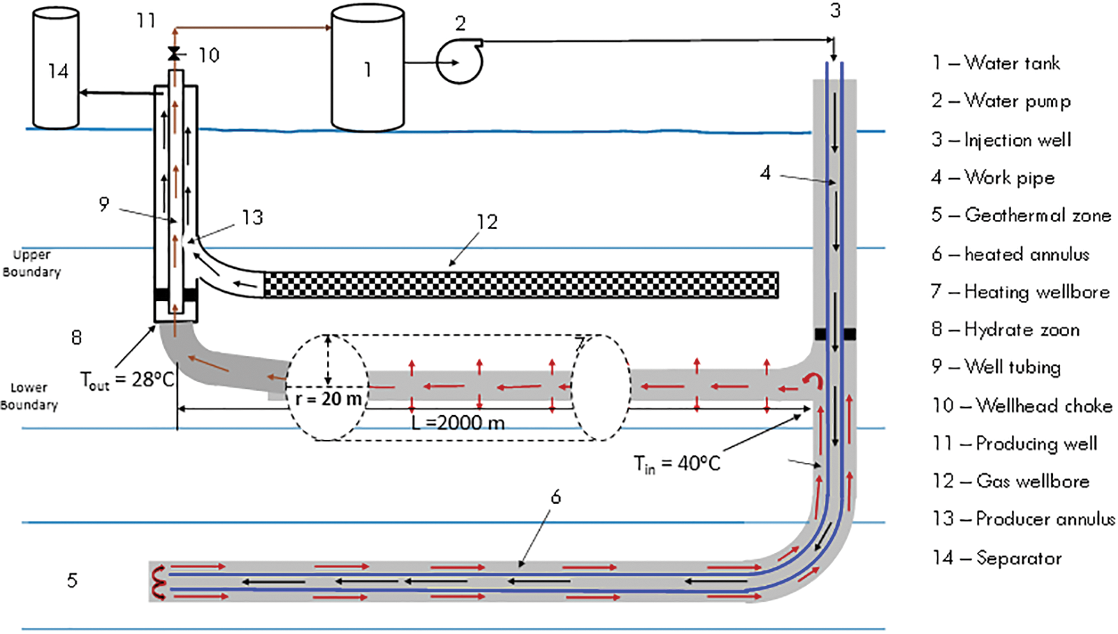
Figure 1: Heat transfer schematic of geothermal well to gas hydrate formation (modified from Fu et al. [33])
Since the detailed derivation of the model has been described previously, the final equations are represented here. The equation for predicting future reservoir temperature is:
To solve the equation for future reservoir temperature Exponential integral
Qrw defines the flow rate of heat from the wellbore to the reservoir which can be calculated by:
where Cp = heat capacity of the fluid inside the wellbore (
The validity of the model is constrained by a specific time frame. The inlet temperature represents the upper limit of the achievable temperature. In theory, an infinite amount of time is necessary to reach the temperature within the reservoir.
2.2 Model for Well Productivity
The productivity model for horizontal wells proposed by Joshi [36] was subject to modification by subsequent researchers to incorporate the influence of pseudo-pressure and non-Darcy flow [37]. The equation is:
where,
where qg = gas well production rate (Mscf/day);
The technique of pseudo-pressure is commonly employed in order to standardize the viscosity and compressibility pressure of the gas, thereby compensating for the fluctuations in these properties that occur at varying pressures within an unconventional reservoir [37]. In general, it is defined as:
The pseudo-pressure data used here are generated using the spreadsheet program PseudoPressure.xls of Guo et al. [37].
It is evident that real gas pseudo-pressure increases proportionally with the increased heating of the gas hydrate reservoir. Applying Eq. (3) to both non-heated and heated reservoir conditions, we get:
and
where
here FOI is the fold of increment in well productivity because of reservoir heating during the swapping process.
The production of gas from Class 1 W gas hydrate reservoirs is anticipated to occur only after the reservoir pressure descends below the hydrate dissociation pressure [38]. Thus, it is necessary to compute the
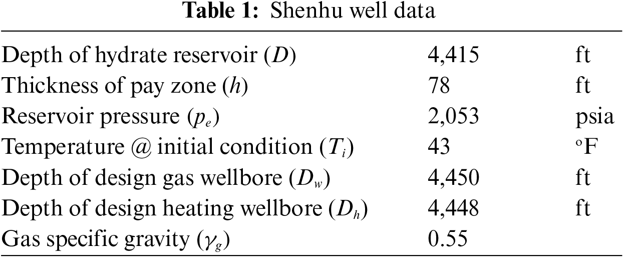
The present section utilizes data obtained from the Shenhu natural gas hydrate reservoir located on the North Continental Slope of the South China Sea to expound on the FOI of wells that employ the geothermal-assisted CH4-CO2 swapping technique [39]. With permeabilities as low as 1.5 mD and hydrate saturations as low as 34% [40], the gas hydrate reservoir contains clayey silt. Well productivity [34,41] requires access to some fundamental information, which is provided in Table 1.
The well structure depicted in Fig. 1 is accompanied by a summary of model parameter values in Table 2. The result of Fu et al. [33] inter-wellbore heat transfer model is plotted in Fig. 2. It shows that the temperature of the fluid at the entrance of the heating wellbore should increase from 29°C to 40°C when the fluid flow rate is increased from 0.004 to 0.01 m3/s. The fluid temperature at the exit of the heating wellbore is predicted to be 28°C with a flow rate of 0.01 m3/s.
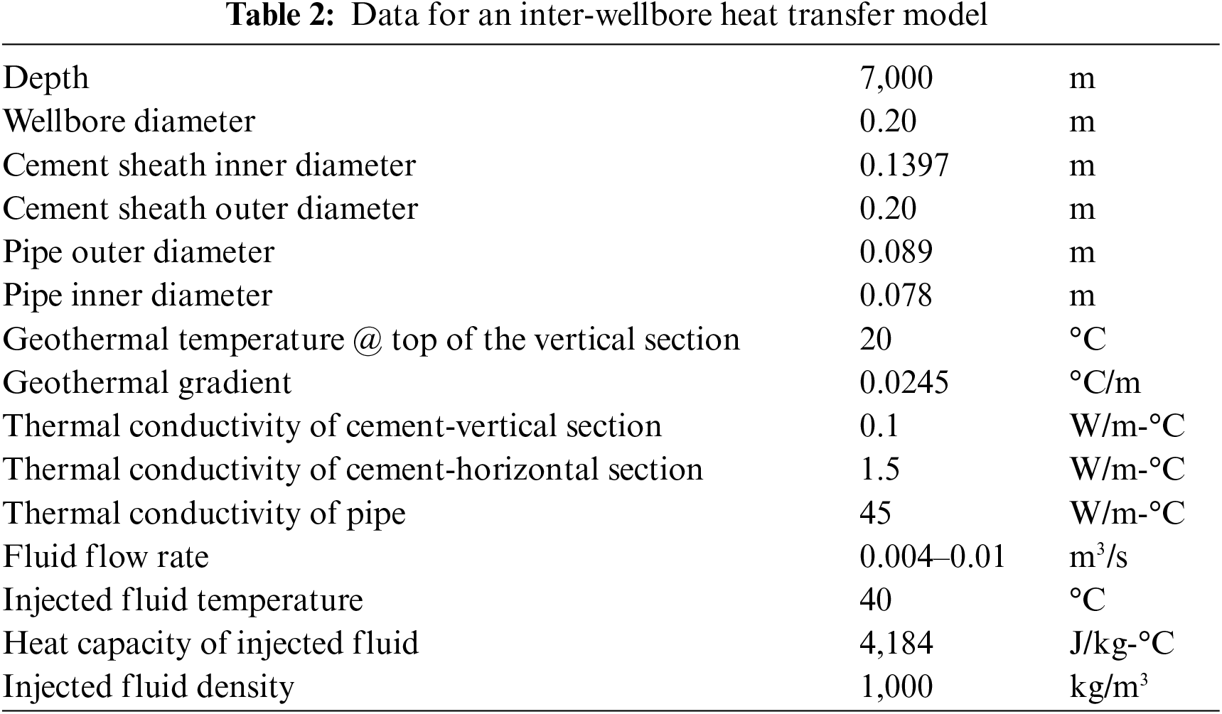
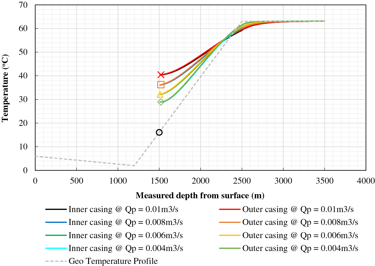
Figure 2: Fluid temperature profiles for inter-wellbore heat transfer
The present discourse concerns the transmission of heat within the gas hydrate reservoir, utilizing the fundamental information provided in Table 3. Fig. 3 displays the 15°C front estimated by Eq. (1) as a variable of fluid circulation duration. As anticipated, the velocity of front propagation demonstrates a decrease over time in a radial system of heat transfer. Based on the curve, it can be inferred that the front will propagate from the top to bottom of the reservoir boundaries within a distance of 39 feet (12 m) in approximately 0.35 years (equivalent to 4.26 months). Based on the given data, it can be inferred that the dissociation of all gas hydrates within a distance of 39 feet from the wellbore will occur in a time span of 4.26 months. After the cessation of fluid circulation, the front will exhibit lateral expansion beyond the upper and lower boundaries.
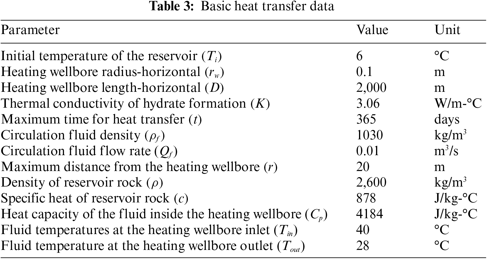
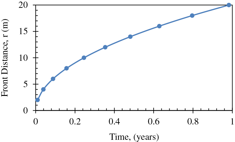
Figure 3: Front advancement profile for dissociation temperature 15°C [34]
The temperature changes over time at a distance of 20 m from the heating wellbore, as calculated by Eq. (1), is depicted in Fig. 4. Based on the data, it can be inferred that the temperature in the proximity of the heating wellbore, at a distance of 20 m, is anticipated to attain the critical temperature for hydrate dissociation, which is 15°C, following a fluid circulation period of roughly 11 months. The figure depicts a plateaued trend during the initial six-month period, where dissociation has not yet commenced, and the temperature remains constant at the reservoir's initial temperature of 6°C or 43°F. Both Figs. 3 and 4 were previously generated by Mahmood et al. [34] for the purpose of predicting front advancement and future reservoir temperature.
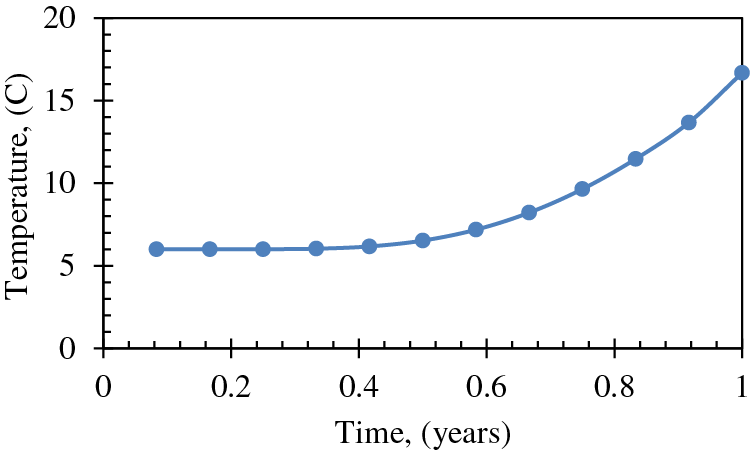
Figure 4: Change of temperature over time at a distance of 20 m from the heating wellbore [34]
Fig. 5 displays the equilibrium curves pertaining to the hydrate phase of CH4 and CO2. At location A, the reservoir is characterized by an initial condition of 2,053 psi pressure and 279° K temperature. The green color on the B-C axis represents the ideal bottom hole pressures and temperatures for the flow of geothermal energy. Table 4 presents a subset of the data obtained from the gas hydrate dissociation line and the green line. The non-linear correlation between the FOI and the temperature of the heated reservoir can be observed in Fig. 6, as demonstrated by Eq. (9). When the temperature of the reservoir is approximately 16 degrees Celsius, the ‘Fold of Increment (FOI)' exceeds 5.
Figure 5: CH4 and CO2 hydrate phase equilibrium curves (modified from Sloan et al. [4])
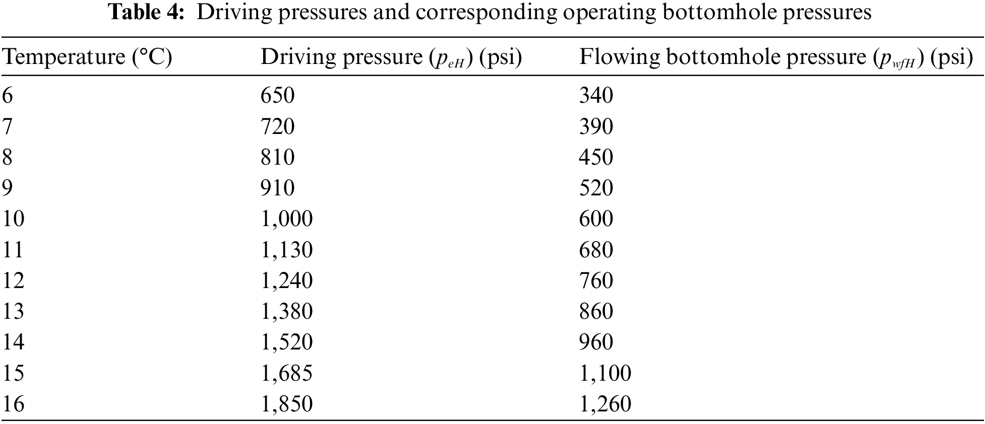
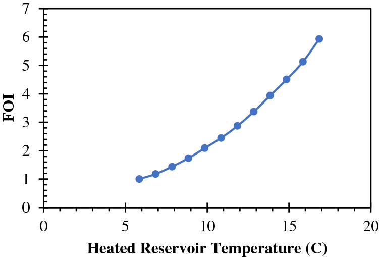
Figure 6: Calculated FOI vs. heated reservoir temperature
Assumptions inherent to mathematical modeling introduce uncertainty into the mathematical models described here. The heat transfer model for this simplified process was previously derived by researchers. The heat transfer model does not consider heat convection, which may arise in the event of gas production during the heating phase. The heat that is lost to the byproduct gas causes the model to overstate the efficiency of the heat transfer. Heat transfer modeling could not account for reservoir temperature changes caused by depressurization (Wang et al. [26]). As a corollary, this should cause the efficiency of heat transport to be overestimated. The dissociated gas’s pressure will increase because of heating, which should reduce the pace of hydrate dissociation. Second, under the starting condition assumed by the well productivity model, no free gas is present in the reservoir, which is a Class 1 W hydrate reservoir. When applied to other types of reservoirs containing free gas initially, this should cause the model to overestimate productivity. The dissociation pressure of hydrates at the dissociated zone’s external flow boundary of the reservoir is known to be the driving pressure in the well productivity model. Since the boundary distance varies with time and is governed by heat transfer efficiency, it stands to reason that well productivity would similarly vary with the rate of fluid circulation.
The research investigated the efficiency of gas wells in gas hydrate reservoirs which are stimulated geothermally by swapping CH4 for CO2. Data from the northern South China Sea’s Shenhu gas hydrate reservoir was used in a case study. The following inferences can be made:
1. Initially, the propagation of the heat-front within a gas hydrate reservoir follows the expected behavior of a radial heat-transfer system. However, over time, the pace of this propagation slows down, consistent with the predictions of the heat conduction model. Based on the simulation outcomes, it can be inferred that the heat front within the gas hydrate reservoir under investigation will propagate towards its upper and lower boundaries, spanning a distance of 39 feet (equivalent to 12 m) within a time frame of 0.35 years (or 4.26 months). Consequently, it can be inferred that the dissociation and consequent release of gas from all gas hydrates located within a 39-foot radius of the heated wellbore will occur within a period of 4.26 months.
2. Furthermore, the utilization of geothermal heating during the CO2 exchanging process has the potential to significantly enhance the initial productivity of wells located in heated reservoirs. The non-linear relationship between the increase in fold and the elevation of reservoir temperature is evidenced by the rate of ascent. The anticipated outcome suggests that the increase will exceed a quintuple factor when the gas hydrate reservoir undergoes a temperature elevation from 6°C to 16°C.
3. The mathematical models utilized in this study neglected a crucial factor that could have potentially enhanced the productivity of the well. Specifically, the models failed to account for the heat convection resulting from the flow of CO2 into the gas reservoir. The utilization of mathematical models in geothermal-stimulated reservoirs may result in over-prediction of well productivity due to the deviance that may arise from the underlying assumptions made. Future research should consider various factors such as heat convection, temperature reduction due to the presence of free gas in the hydrate reservoir, depressurization, and gas pressure elevation due to heating.
4. Geothermal stimulation of the CH4-CO2 swapping process is an effective and promising way for infusing CO2 into gas hydrate reservoirs to permanently lock the CO2 there in solid state. Research on the CO2 mass transfer rate within gas hydrate reservoirs is desirable.
Acknowledgement: The authors are grateful to BIRD for funding the project “Safe, Sustainable, and Resilient Development of Offshore Reservoirs and Natural Gas Upgrading through Innovative Science and Technology: Gulf of Mexico–Mediterranean,” through Contract No. EC-19 Fossil Energy.
Funding Statement: This research is funded by Israel-U.S. Binational Industrial Research and Development (BIRD). Program Title: “Safe, Sustainable and Resilient Development of Offshore Reservoirs and Natural Gas Upgrading through Innovative Science and Technology: Gulf of Mexico–Mediterranean (GoMed Consortium)”. Contract No. EC-19 Fossil Energy. https://us-isr-energycenter.org/fossil-energy/.
Author Contributions: The authors confirm contribution to the paper as follows: study conception and design: Boyun Guo, Md Nahin Mahmood; data collection: Md Nahin Mahmood; analysis and interpretation of results: Boyun Guo, Md Nahin Mahmood; draft manuscript preparation: Boyun Guo, Md Nahin Mahmood. All authors reviewed the results and approved the final version of the manuscript.
Availability of Data and Materials: The data used in this study are from Shenhu Area of South China Sea. The public data has been accessed from some of the previous research of the same authors cited in the reference whereas some other data cannot be disclosed due to confidentiality issues.
Conflicts of Interest: The authors declare that they have no conflicts of interest to report regarding the present study.
References
1. Allison, E. (2008). Methane hydrates in future energy: Improved, sustainable and clean options for our planet. UK: Elsevier. [Google Scholar]
2. Dawe, R. A., Thomas, S. (2007). A large potential methane source-Natural gas hydrates. Energy Sources, Part A: Recovery, Utilization, and Environmental Effects, 29(3), 217–229. [Google Scholar]
3. Kvenvolden, K. A. (1993). Gas hydrates-geological perspective and global change. Reviews of Geophysics, 31, 173–187. [Google Scholar]
4. Sloan, E. D., Koh, C. A. (2008). Clathrate hydrates of natural gases. USA: CRC Press. [Google Scholar]
5. Nelson, R. D., Fleyfall, F., Dubois, R., Vitthal, S., Blaine, K. S. (2000). A novel gas-hydrate inhibitor for deepwater frac-pack and subsea environments. Proceedings of the SPE International Symposium on Formation Damage Control, Lafayette, USA. [Google Scholar]
6. Moreno, B., Haydell, G., Landry, L. (2009). Critical data needs for design of frac-pack completions in today’s oilfield environment. Proceedings of the Offshore Europe Meeting, Aberdeen, UK. [Google Scholar]
7. Stewart, B. R., Mullen, M. E., Ellis, R. C., Norman, W. D., Miller, W. K. (1995). Economic justification for fracturing moderate to high permeability formations in sand control environments. Proceedings of the SPE Annual Technical Conference and Exhibition, Dallas, USA. [Google Scholar]
8. Ohgaki, K., Takano, K., Sangawa, H., Matsubara, T., Nakano, S. (1996). Methane exploitation by carbon dioxide from gas hydrates—phase equilibria for CO2-CH4 mixed hydrate system. Journal of Chemical Engineering of Japan, 29(3), 478–483. [Google Scholar]
9. Guo, B., Zhang, H. (2022). Mathematical modeling of the dynamic temperature profile in geothermal-energy-heated natural gas hydrate reservoirs. Sustainability, 14(5), 2767. https://doi.org/10.3390/su14052767 [Google Scholar] [CrossRef]
10. Ahmadi, G., Ji, C., Smith, D. H. (2007). Production of natural gas from methane hydrate by a constant downhole pressure well. Energy Conversion and Management, 48(7), 2053–2068. [Google Scholar]
11. Li, X., Xu, C. G., Zhang, Y., Ruan, X. K., Li, G. et al. (2016). Investigation into gas production from natural gas hydrate: A review. Applied Energy, 172, 286–322. [Google Scholar]
12. Li, G., Tang, L. G., Huang, C., Feng, Z. P., Fan, S. S. (2006). Thermodynamic evaluation of hot brine stimulation for natural gas hydrate dissociation. CIESC Journal, 57(9), 2033–2038. [Google Scholar]
13. Kawamura, T., Ohtake, M., Sakamoto, Y., Yamamoto, Y., Haneda, H. et al. (2007). Experimental study on steam injection method using methane hydrate core samples. Proceedings of the Seventh ISOPE Ocean Mining Symposium, pp. 83–86. Lisbon, Portugal. [Google Scholar]
14. Li, G., Li, X. S., Tang, L. G., Li, Q. P. (2008). Control mechanisms for methane hydrate production by thermal stimulation. Proceedings of the 6th International Conference on Gas Hydrates, Vancouver, Canada. [Google Scholar]
15. Kawamura, T., Yamamoto, Y., Ohtake, M., Sakamoto, Y., Komai, T. et al. (2005). Experimental study on dissociation of hydrate core sample accelerated by thermodynamic inhibitors for gas recovery from natural gas hydrate. Proceedings of the 5th International Conference on Gas Hydrates, Trondheim, Norway. [Google Scholar]
16. Najibi, H., Chapoy, A., Haghighi, H., Tohidi, B. (2009). Experimental determination and prediction of methane hydrate stability in alcohols and electrolyte solutions. Fluid Phase Equilibria, 27, 127–131. [Google Scholar]
17. Moridis, G. J., Reagan, M. T. (2007). Strategies for gas production from oceanic class 3 hydrate accumulations. Proceedings of the Offshore Technology Conference, Houston, USA. [Google Scholar]
18. Moridis, G. J., Reagan, M. T. (2007). Gas production from oceanic class 2 hydrate accumulations. Proceedings of the Offshore Technology Conference, Houston, USA. [Google Scholar]
19. Makogon, Y. F. (1997). Hydrates of hydrocarbons. USA: Penn Well Publishing. [Google Scholar]
20. Kurihara, M., Funatsu, K., Ouchi, H., Masuda, Y., Narita, H. (2005). Investigation on applicability of methane hydrate production methods to reservoirs with diverse characteristics. Proceedings of the 5th International Conference on Gas Hydrates, pp. 714–725. Trondheim, Norway. [Google Scholar]
21. Hong, H., Pooladi-Darvish, M. (2005). Simulation of depressurization for gas production from gas hydrate reservoirs. Journal of Canadian Petroleum Technology, 44, 39–46. [Google Scholar]
22. Qin, X., Liang, Q., Ye, J., Yang, L., Qiu, H. et al. (2020). The response of temperature and pressure of hydrate reservoirs in the first gas hydrate production test in South China Sea. Applied Energy, 278, 115649. [Google Scholar]
23. Moridis, G. J., Collett, T. S., Dallimore, S. R., Satoh, T., Hancock, S. et al. (2004). Numerical studies of gas production from several CH4 hydrate zones at the mallik site. Journal of Petroleum Science and Engineering, 43(3–4), 219–238. [Google Scholar]
24. Dickens, G. R., Quinby-Hunt, M. S. (1994). Methane hydrate stability in seawater. Geophysical Research Letters, 21(19), 2115–2118. [Google Scholar]
25. Wang, Y., Feng, J., Li, X., Zhang, Y., Li, G. (2015). Analytic modeling and large-scale experimental study of mass and heat transfer during hydrate dissociation in sediment with different dissociation methods. Energy, 90, 1–18. [Google Scholar]
26. Wang, Y., Feng, J., Li, X., Zhang, Y. (2016). Experimental and modeling analyses of scaling criteria for methane hydrate dissociation in sediment by depressurization. Applied Energy, 181, 299–309. [Google Scholar]
27. Wang, Y., Feng, J., Li, X., Zhang, Y., Chen, Z. (2018). Fluid flow mechanisms and heat transfer characteristics of gas recovery from gas-saturated and water-saturated hydrate reservoirs. International Journal of Heat and Mass Transfer, 118, 1115–1127. [Google Scholar]
28. Cha, M., Shin, K., Lee, H., Moudrakovski, I. L., Ripmeester, J. A. et al. (2015). Kinetics of methane hydrate replacement with carbon dioxide and nitrogen gas mixture using in situ NMR spectroscopy. Environmental Science &Technology, 49(3), 1964–1971. [Google Scholar]
29. Davies, S. R., Sloan, E. D., Sum, A. K., Koh, C. A. (2010). In situ studies of the mass transfer mechanism across a methane hydrate film using high-resolution confocal raman spectroscopy. The Journal of Physical Chemistry C, 114(2), 1173–1180. [Google Scholar]
30. Zhao, J., Zhang, L., Chen, X., Zhang, Y., Liu, Y. et al. (2016). Combined replacement and depressurization methane hydrate recovery method. Energy Exploration & Exploitation, 34(1), 129–139. [Google Scholar]
31. Chen, Y., Gao, Y. H., Chen, L. T., Wang, X. R., Liu, K. et al. (2019). Experimental investigation of the behavior of methane gas hydrates during depressurization-assisted CO2 replacement. Journal of Natural Gas Science and Engineering, 61, 284–292. [Google Scholar]
32. Pandey, J. S., Solms, N. V. (2019). Hydrate stability and methane recovery from gas hydrate through CH4–CO2 replacement in different mass transfer scenarios. Energies, 12(12), 2309. [Google Scholar]
33. Fu, C., Guo, B., Shan, L., Lee, J. (2021). Mathematical modeling of heat transfer in y-shaped well couples for developing gas hydrate reservoirs using geothermal energy. Journal of Natural Gas Science and Engineering, 96, 104325. [Google Scholar]
34. Mahmood, M. N., Guo, B. (2023). Gas production from marine gas hydrate reservoirs using geothermal-assisted depressurization method. Advances in Geo-Energy Research, 7(2), 90–98. [Google Scholar]
35. Abramowitz, M., Stegun, I. A. (1965). Handbook of mathematical functions with formulas, graphs, and mathematical tables, vol. 55. USA: US Department of Commerce. [Google Scholar]
36. Joshi, S. D. (1988). Augmentation of well productivity with slant and horizontal wells. Journal of Petroleum Technology, 40(6), 729–739. [Google Scholar]
37. Guo, B., Ghalambor, A. (2012). Natural gas engineering handbook. 2nd edition. USA: Gulf Publishing Company. [Google Scholar]
38. Ubeyd, I. M., Merey, S. (2020). Gas production from methane hydrate reservoirs in different well configurations: A case study in the conditions of the Black Sea. Energy & Fuels, 35(2), 1281–1296. [Google Scholar]
39. Liu, C. L., Ye, Y., Meng, Q. (2012). The characteristics of gas hydrates recovered from Shenhu Area in the South China Sea. Marine Geology, 307-310, 22–27. [Google Scholar]
40. Yu, T., Guan, G., Wang, D., Song, Y., Abudula, A. (2021). Effect of horizontal-well systems on the long-term gas hydrate production behavior at the second Shenhu test site. Journal of Natural Gas Science and Engineering, 95, 104200. [Google Scholar]
41. Su, M., Yang, R., Wu, N. Y. (2014). Structural characteristics in the Shenhu Area, northern continental slope of South China Sea, and their influence on gas hydrate. Acta Geologica Sinica, 88(3), 318–326. [Google Scholar]
Cite This Article
 Copyright © 2023 The Author(s). Published by Tech Science Press.
This work is licensed under a Creative Commons Attribution 4.0 International License , which permits unrestricted use, distribution, and reproduction in any medium, provided the original work is properly cited.
 Downloads
 Citation Tools