
 Submit a Paper
 Propose a Special lssue
 Open Access
ARTICLE

A Double-Ended Protection Principle for an LCC-VSC-MTDC System with Strong Anti-Interference Ability
School of Electrical Engineering, Beijing Jiaotong University, Beijing, 100044, China
* Corresponding Author: Dahai Zhang. Email:
Energy Engineering 2023, 120(2), 299-316. https://doi.org/10.32604/ee.2023.023532
Received 30 April 2022; Accepted 10 June 2022; Issue published 29 November 2022
 View Full Text
 Download PDF
Abstract
The DC grid technology of multi-power supply and multi-drop-point power reception is an effective solution for large-scale renewable energy integration into the power grid. Line-commutated converter-Voltage source converter (LCC-VSC) power grids are one of the more important developmental directions of the future power grid that have occured in recent years. But the multi-terminal high voltage direct current system has the problems of inconsistent boundary characteristics, inconsistent control, and fault response characteristics, which puts higher requirements on the protection scheme. Thus, a completely new protection principle is proposed in this paper. Firstly, the fault characteristics of distributed capacitance current are analyzed. The reactive power calculated by the distribution parameters of different frequencies is different. Subsequently, the fault characteristics of DC reactive power are analyzed, and a DC reactive power extraction algorithm is proposed. The polarity of the multi-band DC reactive power is used to construct the protection scheme. Finally, the LCC-VSC power grid model verifies the correctness and superiority of the proposed protection scheme. The proposed scheme uses DC reactive power instead of fault current to solve the long delay problem caused by distributed capacitance. Compared with the prior art, the proposed solution is not affected by distributed capacitance and has a stronger anti-interference ability (600 + 10 dB + 1 ms).Keywords
LCC-VSC system integrates the advantages of traditional DC transmission technology, has the advantages of large transmission capacity and long-distance, and realizes multi-drop power reception [1]. Compared with conventional UHVDC, LCC-VSC-MTDC has the following advantages: it saves valuable transmission corridor resources; greatly reduces the cost of new energy grid-connected; and delivers clean energy farther and more smoothly [2]. At present, China has already started some hybrid DC transmission systems. However, there is still little research available regarding protection schemes for three-terminal hybrid HVDC projects, which is, of course, not conducive to understanding or maximizing the reliable operations of hybrid HVDC systems [3]. Currently, the LCC-VSC-MTDC system still draws on the protection scheme of the traditional DC system. It is, therefore, necessary to put forward a reliable and safe protection scheme to ensure the reliable operation of the system [4].
At present, the backup protection schemes of the DC system include the following: differential protection, protection based on boundary elements, and waveform-based correlation protection. Current differential protection is the most widely used backup protection scheme, and its purpose is to compensate for the shortcomings of the traveling wave main protection scheme. However, the distributed capacitance causes a delay of 1100 ms, which is difficult to accept in a DC system. However, a delay of up to seconds causes the current differential protection to have little chance to act [5,6]. Reference [7] used energy at different frequencies to identify fault types. This scheme solves the problem of distributed capacitance in the frequency domain, but it requires the existence of a current-limiting reactor. Reference [8] proposed current differential protection and proposes a communication strategy for this protection. But this scheme does not consider the influence of distribution parameters [9]. However, the boundary element consistency is the prerequisite of this scheme, which does not exist in the LCC-VSC-MTDC system. The differential protection of this discussion is susceptible to the influence of distributed capacitance and has insufficient adaptability in LCC-VSC-MTDC.
The scheme based on the boundary element relies on the characteristic that the boundary element attenuates different frequency signals to construct the criterion. Reference [10] relied on the characteristics concerning the current-limiting reactor and how it attenuates high-frequency signals to construct a voltage-based protection scheme. In order to analyze the fault signal in the frequency domain, reference [11] and reference [12] each introduced mathematical tools such as wavelet transform to support the construction of protection criteria. The LCC-VSC-MTDC has inconsistent types of boundary elements and inconsistent strengths, so the adaptability of the above protection scheme is greatly reduced [13].
The protection scheme based on waveform similarity is also a research hotspot [14–16]. There are many types of research on protection schemes based on current waveform similarity or traveling wave similarity. The foundation of this type of scheme is the consistency of the waveform. But they have the following problems when they are applied to the system: 1) The inconsistency of the control strategy and fault response of the LCC-VSC-MTDC system leads to irrelevant waveforms, which makes the system lose the application foundation of this type of protection scheme. 2) The similarity-based protection scheme requires stricter communication synchronization. However, the low damping characteristics of the DC system lead to a large fault current rise rate, which may lead to the protection failure.
The main work of this paper is as follows: 1) The concept of high and low-frequency DC reactive power and its fault characteristics are analyzed. 2) The extraction algorithm, frequency range, and DC reactive power calculation scheme are given. 3) Theoretical analysis and simulation verify the reliability and superiority of the proposed protection scheme.
The content structure of each section of the paper is as follows: Section 2 puts forward the concept of DC reactive power and analyzes its fault characteristic. Subsequently, the calculation method of DC reactive power is given in Section 3. Section 4 is the overall flow of the proposed scheme, and the simulation results and conclusions are in Sections 5 and 6, respectively.
2 Analysis of DC Reactive Power
The disorder of the distributed capacitor current leads to the long delay of the original backup protection. This section proposes a scheme to describe the law of distributed capacitor current by using DC reactive power and analyzing the distributed parameters’ frequency characteristics. The concept of DC reactive power and its fault characteristics are simultaneously analyzed in this section.
2.1 Simulation Model and Influence of Distributed Capacitance Current
This article takes the LCC-VSC-MTDC (Fig. 1) transmission system as the object of research. The sending end of the system is an LCC converter station, and the two receiving ends are both MMC converter stations. The DC line is divided into two sections, Line 1 and Line 2. Line 1 is connected to one of the converter stations, MMC1, through a DC busbar and then to the next receiving-end converter station MMC2 through Line 2. The detailed parameters of the system are shown in Table S1 (Appendix A). The frequency-dependent model of the transmission line is shown in Fig. S1. In addition, the sampling frequency of the proposed scheme is set to 20 kHz.
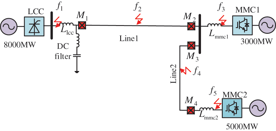
Figure 1: Topological structure of LCC-VSC-MTDC DC grid
Take Line 1 as an example, Fig. 2 represents the flow of distributed capacitance current. Among Fig. 2,
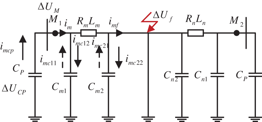
Figure 2: The flow direction of the distributed capacitance current
When the line faults, the distributed capacitance will be charged (
2.2 Analysis of Distributed Parameters
To study the frequency characteristics, this paper ignores other components and analyzes the line’s fault point. The network diagram of line distribution parameters is shown in Fig. 3.
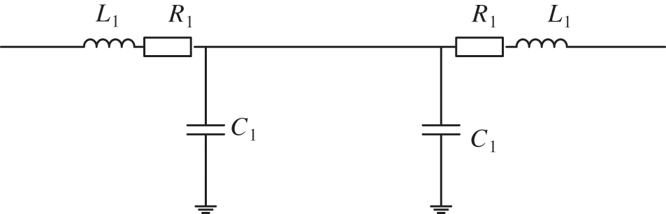
Figure 3: Line distribution parameters
where
The Eq. (1) represents the frequency characteristic of the line input impedance. According to the characteristics of the resonant circuit, the equivalent impedance is zero when the circuit is in series resonance. When defining frequency is:
When
2.3 Calculation Scheme of DC Reactive Power
DC systems can only transmit active power but not reactive power. A healthy DC system only has partial reactive power in the boundary elements [17]. However, Section 2.2 analysis shows that line distribution parameters can generate or absorb reactive power during faults. The DC reactive power determined by the distribution parameters provides the possibility for fault identification.
Transient signals are often non-sinusoidal signals, and there are many definitions of reactive power for non-sinusoidal signals [18]. Among them, the most applied scheme calculates the integral average value of the phase-shifted voltage or current.
where k is the order of harmonics;
where
2.4 Fault Characteristics of DC Reactive Power
Take Line 1 as an example to analyze the fault characteristics of DC reactive power. Fig. 4 shows the fault characteristics of DC reactive power at different faults.
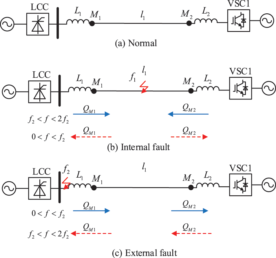
Figure 4: Polarity of DC reactive power. (a) Normal. (b) Internal faults. (c) External faults
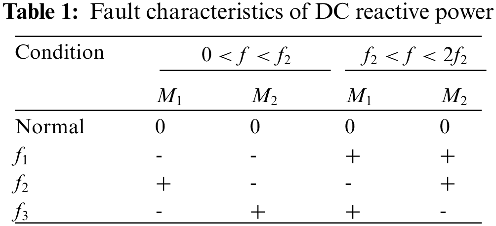
Fig. 4a represents the normal state of the line, and there is no DC reactive power at this time. Fig. 4b represents an internal fault. The line parameters in the range of
Therefore, the polarity of DC reactive power in the fixed frequency range can distinguish internal faults from external faults. The fault characteristics of DC reactive power at different faults are listed in Table 1. The characteristic fault analysis of DC reactive power at both ends of Line 2 is the same as that of Line 1.
3 DC Reactive Power Calculation Method
Digital phase-shift measurement algorithms are commonly used to phase-shift voltage or current signals. The basic idea of this method is to translate the sampling points. The limitation of this method is that it is only applicable to signals containing one frequency and is greatly affected by harmonics; the number of sampling points in each cycle is required to be an integer multiple. Obviously then, this algorithm is not suitable for the fault transient process with more harmonic components. In order to better realize the accurate phase shifting of various harmonic components in the transient process, the Hilbert transforms phase-shifting algorithm is introduced in this section.
Hilbert transform is performed on a continuous signal
where
So the Hilbert transform of the discrete signal
where
S transform is the inheritance and development of wavelet transform and short-time Fourier transform, and it is insensitive to noise [16]. The S transform can be obtained by multiplying the wavelet transform by the phase factor.
where
Use Eq. (8) to decompose the signal to get the information of any frequency.
where
To sum up, the DC reactive power calculation steps are: 1) First, sample the voltage and current signals. Hilbert transform is performed on the sampled voltage signal so that the voltage of each frequency component is translated by 90°. 2) Then, the S transform is used to extract the amplitude of the voltage and current signals. 3) Finally, use the voltage and current signals to calculate the DC reactive power.
The action time of the proposed scheme consists of two parts: algorithm calculation time and communication delay. The calculation formula of the action time (
where
Since the calculation of DC reactive power requires multiple transformations, the calculation time cannot be ignored. Because the protection device of the DC system uses digital signal processing (DSP) to process data, this paper takes TMS320F2818 as an example to analyze the calculation time of the algorithm (
Communication delay is a factor that must be considered in double-ended protection. The longest line in Fig. 1 is 932 km, and the transmission speed of the optical fiber signal is 200 km/ms, so the communication delay (
In summary, the action time of the proposed scheme is 4.66 + 0.671 = 5.331 ms. Compared with the 1100 ms delay of the existing protection scheme, the action speed of the proposed scheme is faster.
4 Protection Principle Process
The occurrence of the fault can be quickly detected by using the amplitude difference between the sampling points before and after. In addition, to prevent accidental activation of the protection caused by disturbance, a threshold must be set to ensure reliability. Therefore, the specific criteria for starting components in this paper are:
where
Section 2 analysis shows that the polarity of DC reactive power is completely different between internal faults and external faults. Therefore, this section selects this feature to establish a fault identification element. The formula is abbreviated as:
where u and i represents the voltage and current obtained after S transformation and Hilbert transformation, respectively. The criterion for the fault identification element is:
where
The proposed protection scheme can be applied to a symmetrical bipolar system. Although there is a coupling phenomenon in the symmetrical bipolar system, the coupled signal generated by the healthy pole is far less than the fault signal. The same reactive power at both poles represents a pole-to-pole fault. Otherwise, the pole with more considerable reactive power is extremely faulty.
where
In summary then, the overall process based on the undistorted factor protection scheme is shown in Fig. 5.
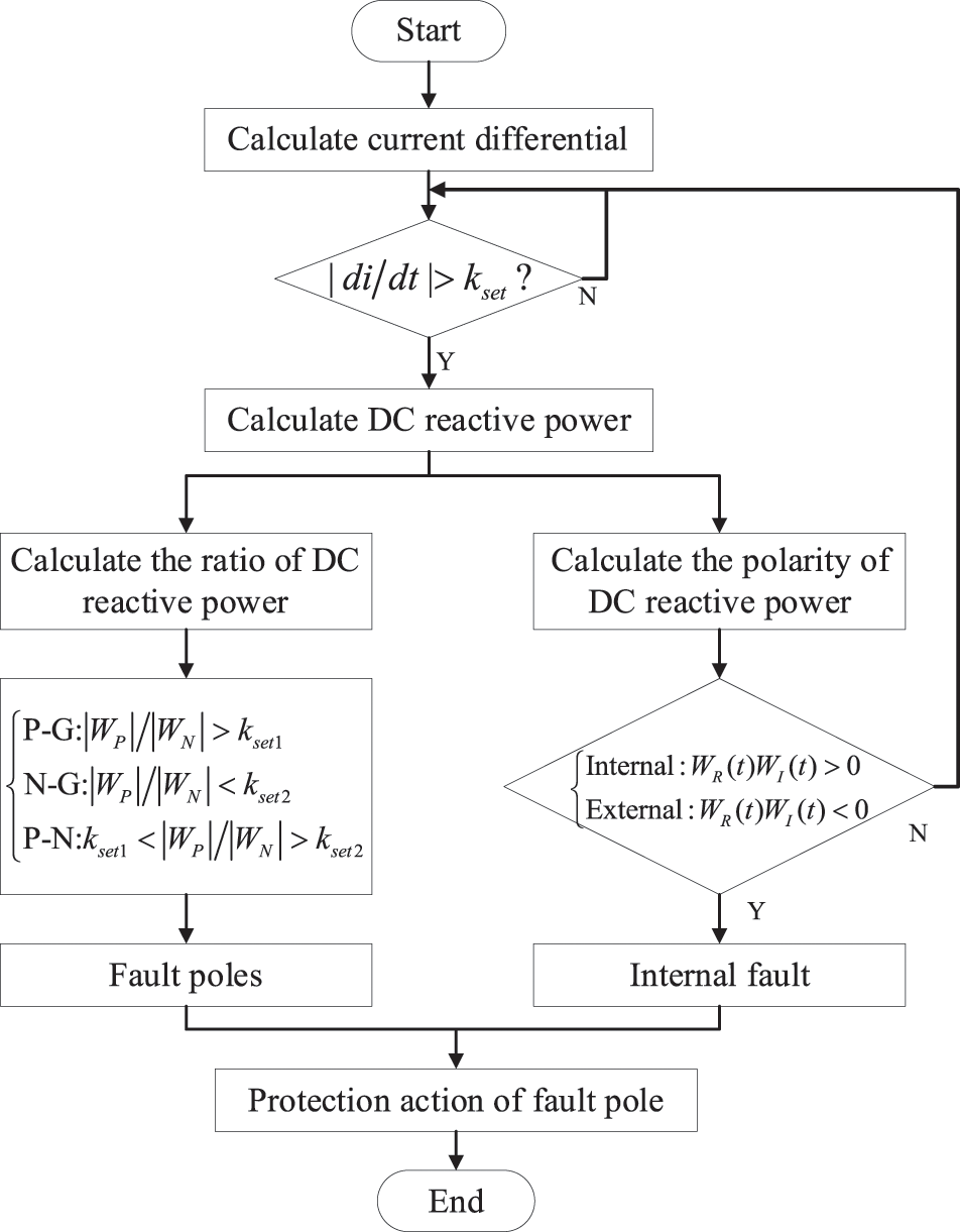
Figure 5: Flow chart of the protection principle
5.1 Internal Fault and External Fault
1) Internal fault
First, take the bipolar fault as an example of simulation. A pole-pole internal fault is set at 1.5 s. The fault location is at the midpoint of the line, and transition resistance is 0 Ω. Set up protection devices at
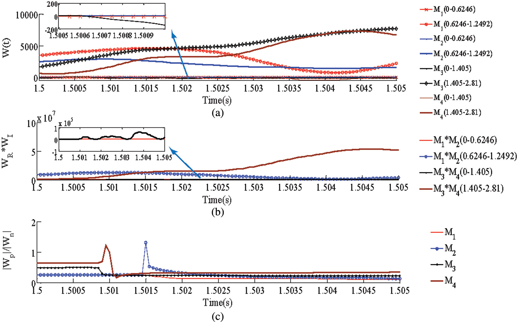
Figure 6: Simulation results of internal faults. (a) DC reactive power at each measuring point. (b) Product of DC reactive power (Fault identification component). (c) The ratio of the absolute value of DC reactive power (Fault pole selection)
The polarity of the DC reactive power of
The product of the DC reactive power (Fig. 6b) at both ends of Line 1 and Line 2 in all frequency ranges is positive. The simulation results satisfy the fault identification criterion equation.
Fig. 6c represents the ratio of positive and negative DC reactive power. Since the DC reactive power of the positive pole and the negative pole of the pole-pole fault are close, the ratio of the positive pole and the negative pole DC reactive power in Fig. 6c is close to 1. The simulation result satisfies the fault pole selection criterion.
2) External fault
Due to space limitations, this article takes external fault
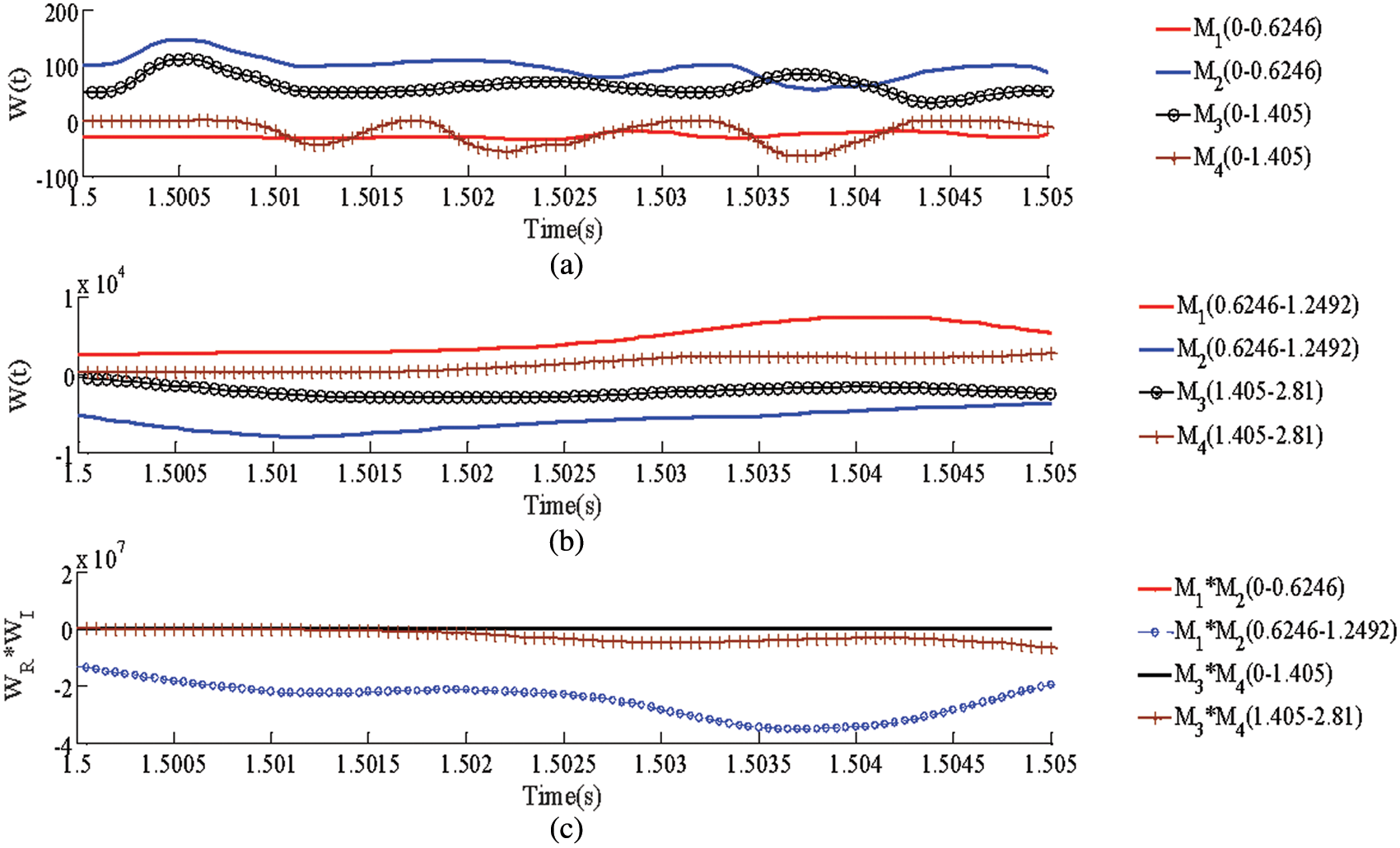
Figure 7: Simulation results of external faults. (a) DC reactive power with (0–0.6246) and (0–0.1.405). (b) DC reactive power with (0.6246–1.2492) and (0.1.405–2.81). (c) Product of DC reactive power (Fault identification component)
Fig. 7a represents the DC reactive power in (0–0.6246) kHz and (0–1.405) kHz when
In summary, the simulation results show that the proposed protection scheme can identify external faults. The simulation results of pole-to-ground faults shown in Table 2 show that the proposed protection scheme can identify pole-to-ground faults.
The disorder of the distributed capacitive current seriously affects the reliability of the double-ended protection scheme. When the transmission line is long, the influence of distributed capacitance cannot be ignored. To verify the ability of the proposed protection scheme to withstand distributed capacitance, this paper takes fault
Figs. 8a and 8b respectively represent the DC reactive power under different distributed capacitances. Fig. 8c represents the product. When an internal fault occurs in the line, the polarity of the DC reactive power at the
Figure 8: Simulation results of the ability to withstand distributed capacitance current. (a) Capacitance characteristic. (b) Inductance characteristic. (c) Product
5.3 Communication Synchronization Error
The longest line of the hybrid DC transmission system is 932 km, and the communication delay is relatively large at this time. Since the synchronization error does not change the polarity of the DC reactive power, the scheme can accept a large communication delay. This section verifies the reliability of the proposed protection scheme by setting different communication delays. The results in Table 3 show that 1 ms is acceptable. For actual projects, the synchronization error of 1 ms can fully meet the requirements.
5.4 Influence of Fault Resistance and Fault Distance
In order to verify the ability of the proposed protection principle to withstand fault resistance and fault distance, a variety of fault conditions are set. Figs. 9a and 9b represent the product of the DC reactive power at both ends. The simulation results show that the product of DC reactive power is positive when an internal fault (
Figure 9: Simulation results of fault distance and fault resistance. (a) Capacitance characteristic. (b) Inductance characteristic
High-frequency noise can easily affect the reliability of traditional traveling wave protection schemes. Anti-noise interference capability is one of the important indicators for testing protection schemes. The protection scheme proposed in this paper uses S transform to extract reactive power, so it has a strong anti-noise ability.
To verify the proposed method considering noise then, 10 ∼30 dB of noise is superimposed on measurements of each test. Figs. 10a and 10b respectively represent the polarity of the DC reactive power product in different frequency bands. Since the S-transform can eliminate high-frequency noise, increasing the noise will not affect the polarity of the DC reactive power. Obviously, the proposed protection scheme can tolerate 10 dB noise interference, and its capability is far stronger than the existing protection scheme (20 dB) [18].
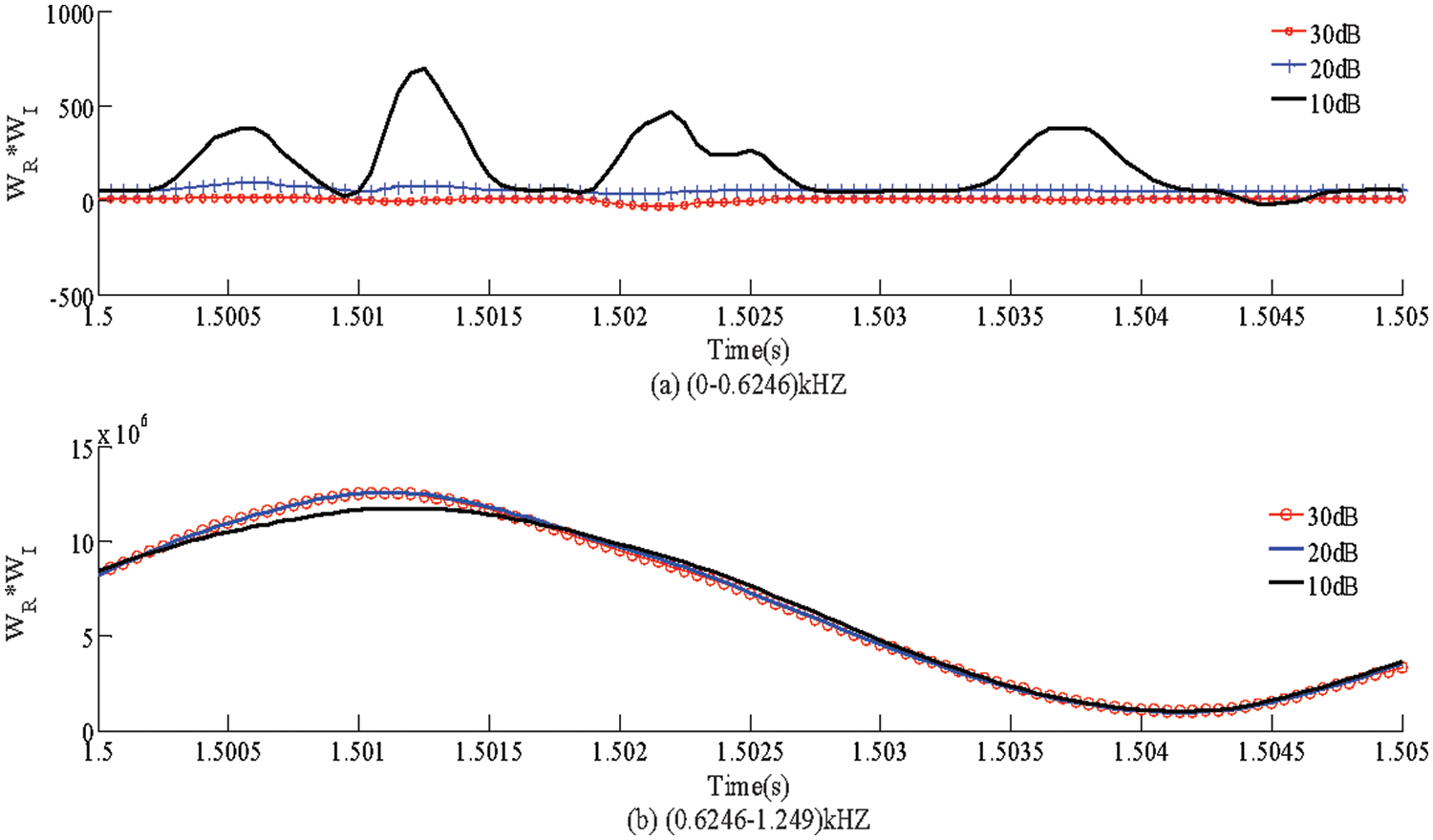
Figure 10: Simulation results of noise tolerance. (a) Capacitance characteristic (b) Inductance characteristic
The anti-interference ability of the proposed scheme has been verified in the previous section. In this section, the performance of several common schemes will be compared. The schemes chosen to compare performance include: the pilot current differential protection scheme [12], energy differential protection scheme [7], fault current similarity factor protection scheme [19], and the proposed protection scheme. Since the fault identification element is the core of the protection scheme, only this element is compared. The fault identification components of the above scheme are:
(1) Scheme 1: Pilot current differential protection scheme [12]
(2) Scheme 2: Energy differential protection scheme [7]
where
(3) Scheme 3: Fault current similarity factor protection scheme [19]
where H represents the similarity coefficient.
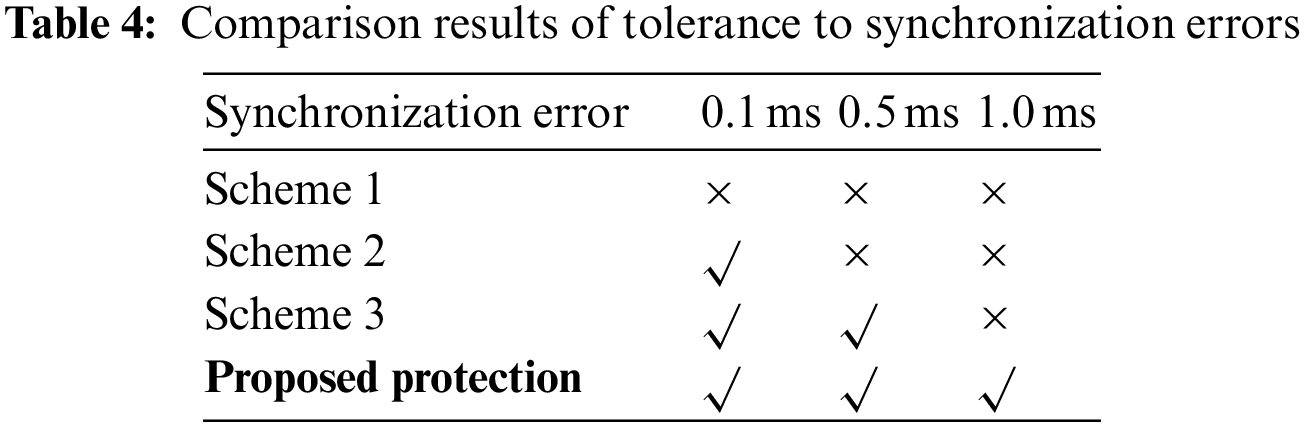
Set different fault resistance, noise, and synchronization error, respectively, and the performance comparison results are shown in Fig. 11 and Table 4. From the simulation results, the following conclusions can be drawn:
(1) Due to the distributed capacitance, the current differential protection (Scheme 1) fails during the transient phase (Fig. 11a). In practical projects, a delay of 1100 ms is often used to solve the problem of distributed capacitance. At this time, the solution cannot meet the requirements of the DC system. Therefore, the current differential protection of the current DC engineering often fails to achieve its role.
(2) Since scheme 2 does not consider the frequency characteristics of long transmission lines, it fails at 400 Ω + 20 dB and 400 Ω + 10 dB (Fig. 11b). The anti-interference ability of scheme 3 is only 200 Ω + 10 dB (Fig. 11c). Compared with the above protection scheme, the proposed protection scheme can operate correctly under 600 Ω + 10 dB. Therefore, the scheme has a stronger anti-interference ability.
(3) The proposed scheme is also more resistant to synchronization errors than traditional protection schemes. This is because other schemes need to transmit the magnitude of the fault information to the opposite end, while the proposed scheme only needs to transmit the polarity.
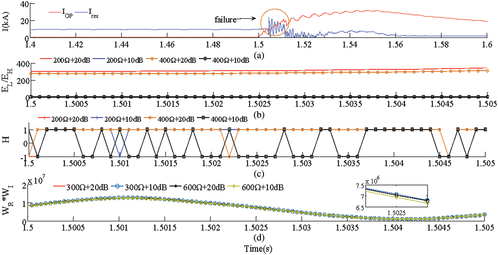
Figure 11: Simulation results for performance comparison. (a) Scheme 1. (b) Scheme 2. (c) Scheme 3. (d) Proposed protection scheme
In conclusion, the proposed protection scheme solves the problem of distributed capacitance and has a better anti-interference ability.
A two-terminal protection scheme based on the DC reactive power is applied to the LCC-VSC-MTDC system. First, the definition of DC reactive power is given, and its frequency characteristics are analyzed. Subsequently, a calculation scheme based on Hilbert and S transform is given. Finally, protection schemes based on capacitive and inductive reactive power are given. The main contributions of this paper are summarized as follows:
1) This paper proposes a scheme for expressing the frequency-dependent characteristics of distribution parameters of reactive power. This scheme turns disordered distribution parameters into ordered reactive power, which solves the problem of current differential protection failure caused by disorder;
2) The proposed protection scheme is suitable for DC systems with different boundary elements and weak boundary elements, and has a larger application range than traditional boundary element protection;
3) The proposed protection scheme enhances the system’s ability to withstand fault resistance (600 Ω) and noise interference (10 dB), which is stronger than the traditional protection scheme.
Acknowledgement: The authors acknowledge the reviewers for providing valuable comments and helpful suggestions to improve the manuscript.
Funding Statement: This work was supported by the National Natural Science Foundation of China-State Grid Joint Fund for Smart Grid (No. U2066210).
Conflicts of Interest: The authors declare that they have no conflicts of interest to report regarding the present study.
References
1. Naushath, M. H., Athula, D. R., Aniruddha, M. G., Loni, T. F. (2018). Investigation of fault ride-through capability of hybrid VSC-LCC multi-terminal HVDC transmission systems. IEEE Transactions on Power Delivery, 34(1), 241–250. [Google Scholar]
2. Yang, S. Z., Xiang, W., Lu, X. J., Zuo, W. P., Wen, J. Y. (2020). An adaptive reclosing strategy for MMC-HVDC systems with hybrid DC circuit breakers. IEEE Transactions on Power Delivery, 35(3), 1111–1123. [Google Scholar]
3. Xiang, W., Lin, W. X., An, T., Wen, J. Y., Wu, Y. N. (2017). Equivalent electromagnetic transient simulation model and fast recovery control of overhead VSC-HVDC based on SB-MMC. IEEE Transactions on Power Delivery, 32(2), 778–788. DOI 10.1109/TPWRD.2016.2607230. [Google Scholar] [CrossRef]
4. Jeremy, S., Athula, D. R. (2016). Fault detection and interruption in an earthed HVDC grid using ROCOV and hybrid DC breakers. IEEE Transactions on Power Delivery, 31(3), 973–981. DOI 10.1109/TPWRD.2014.2364547. [Google Scholar] [CrossRef]
5. Li, R., Xu, L., Yao, L. Z. (2017). DC fault detection and location in meshed multi-terminal HVDC systems based on DC reactor voltage change rate. IEEE Transactions on Power Delivery, 32(3), 1516–1526. DOI 10.1109/TPWRD.2016.2590501. [Google Scholar] [CrossRef]
6. Xiao, H., Li, Y., Liu, R., Duan, X. (2017). Single-end time-domain transient electrical signals based protection principle and its efficient setting calculation method for LCC-HVDC lines. IET Generation Transmission and Distribution, 11(5), 1233–1242. DOI 10.1049/iet-gtd.2016.1159. [Google Scholar] [CrossRef]
7. Li, C. Y., Gole, A. M., Zhao, C. Y. (2018). A fast DC fault detection method using DC reactor voltages in HVDC grids. IEEE Transactions on Power Delivery, 33(5), 2254–2264. [Google Scholar]
8. Song, G. B., Chu, X., Gao, S. P., Kang, X. M., Jiao, Z. B. (2015). A new whole-line quick-action protection principle for HVDC transmission lines using one-end current. IEEE Transactions on Power Delivery, 30(2), 599–607. DOI 10.1109/TPWRD.2014.2300183. [Google Scholar] [CrossRef]
9. Wang, Y. T., Hao, Z. G., Zhang, B. H., Kong, F. (2018). A pilot protection scheme for transmission lines in VSC-HVDC grid based on similarity measure of traveling waves. IEEE Access, 7, 7147–7158. DOI 10.1109/ACCESS.2018.2889092. [Google Scholar] [CrossRef]
10. Gao, S. P., Chu, X., Shen, Q. Y., Jin, X. F., Luo, J. et al. (2015). A novel whole-line quick-action protection principle for HVDC transmission lines using one-end voltage. International Journal of Electrical Power and Energy Systems, 65, 262–270. DOI 10.1016/j.ijepes.2014.10.013. [Google Scholar] [CrossRef]
11. Nagesh, G., Yew, M. Y., Abhisek, U. (2018). Experimental validation of fault identification in VSC-based DC grid system. IEEE Transactions on Industrial Electronics, 65(6), 4799–4809. DOI 10.1109/TIE.2017.2767560. [Google Scholar] [CrossRef]
12. Li, B., Li, Y., He, J. W., Wen, W. J. (2019). A novel single-ended transient-voltage-based protection strategy for flexible DC grid. IEEE Transactions on Power Delivery, 34(5), 1925–1937. [Google Scholar]
13. Zhang, C. H., Song, G. B., Dong, X. Z. (2020). A novel traveling wave protection method for DC transmission lines using current fitting. IEEE Transactions on Power Delivery, 35(6), 2980–2991. [Google Scholar]
14. Chen, L., Lin, X. N., Li, Z. T., Wei, F. R., Zhao, H. et al. (2018). Similarity comparison based high-speed pilot protection for transmission line. IEEE Transactions on Power Delivery, 33(2), 938–948. [Google Scholar]
15. Liu, J., Tai, N. L., Fan, C. J. (2017). Transient-voltage-based protection scheme for DC line faults in the multiterminal VSC-HVDC system. IEEE Transactions on Power Delivery, 32(3), 1483–1494. DOI 10.1109/TPWRD.2016.2608986. [Google Scholar] [CrossRef]
16. Yang, Q. Q., Le, B. S., Aggarwal, R., Wang, Y. W., Li, J. W. (2017). New ANN method for multi-terminal HVDC protection relaying. Electric Power Systems Research, 148, 192–201. DOI 10.1016/j.epsr.2017.03.024. [Google Scholar] [CrossRef]
17. Saleh, K. A., Hooshyar, A., Eisaadany, E. F., Zeineldin, H. H. (2020). Protection of high-voltage DC grids using traveling-wave frequency characteristics. IEEE Systems Journal, 14(3), 4284–4295. DOI 10.1109/JSYST.4267003. [Google Scholar] [CrossRef]
18. Cui, T., Dong, X. Z., Bo, Z. Q., Juszczyk, A. (2011). Hilbert-transform-based transient/intermittent earth fault detection in noneffectively grounded distribution systems. IEEE Transactions on Power Delivery, 26(1), 143–151. DOI 10.1109/TPWRD.2010.2068578. [Google Scholar] [CrossRef]
19. Jia, K., Wang, C. B., Bi, T. S., Feng, T., Zhu, R. (2019). Transient current correlation based protection for DC distribution system. IEEE Transactions on Industrial Electronics, 67(11), 9927–9936. [Google Scholar]
Appendix A
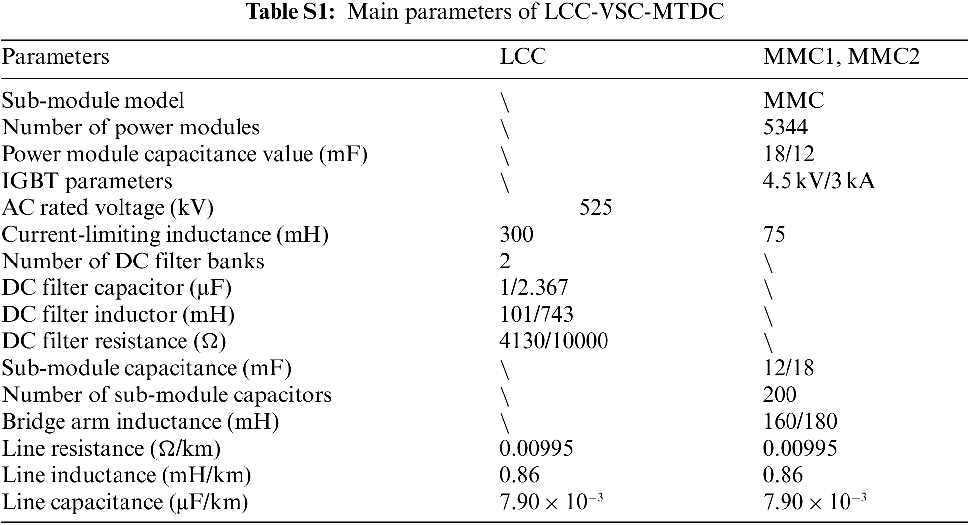
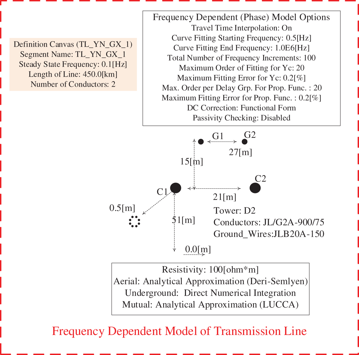
Figure S1: Frequency dependent model of transmission line in PSCAD
Cite This Article
 Copyright © 2023 The Author(s). Published by Tech Science Press.
This work is licensed under a Creative Commons Attribution 4.0 International License , which permits unrestricted use, distribution, and reproduction in any medium, provided the original work is properly cited.
 Downloads
 Citation Tools