
 Submit a Paper
 Propose a Special lssue
 Open Access
ARTICLE

A Two-Layer Fuzzy Control Strategy for the Participation of Energy Storage Battery Systems in Grid Frequency Regulation
1 School of New Energy and Power Engineering, Lanzhou Jiaotong University, Lanzhou, 730000, China
2 Electric Power Research Institute of State Grid Gansu Electric Power Company, Lanzhou, 730070, China
* Corresponding Author: Haiying Dong. Email:
Energy Engineering 2023, 120(6), 1445-1464. https://doi.org/10.32604/ee.2023.027158
Received 17 October 2022; Accepted 09 December 2022; Issue published 03 April 2023
 View Full Text
 Download PDF
Abstract
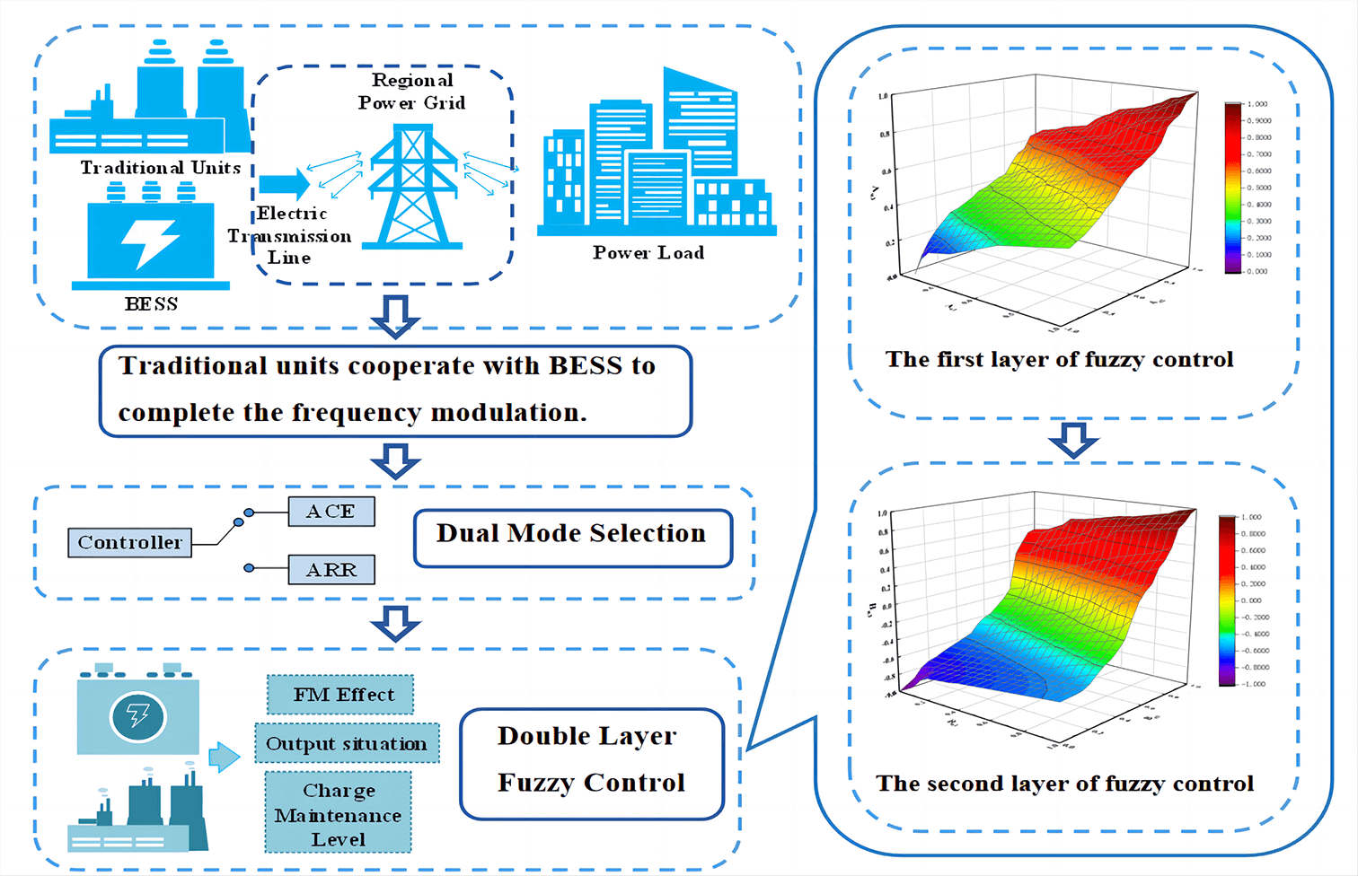
To address the frequency fluctuation problem caused by the power dynamic imbalance between the power system and the load when a large number of new energy sources are connected to the grid, a two-layer fuzzy control strategy is proposed for the participation of the energy storage battery system in FM. Firstly, considering the coordination of FM units responding to automatic power generation control commands, a comprehensive allocation strategy of two signals under automatic power generation control commands is proposed to give full play to the advantages of two FM signals while enabling better coordination of two FM units responding to FM commands; secondly, based on the grid FM demand and battery FM capability, a double-layer fuzzy control strategy is proposed for FM units responding to automatic power generation control commands in a coordinated manner under dual-signal allocation mode to precisely allocate the power output depth of FM units, which can control the fluctuation of frequency deviation within a smaller range at a faster speed while maintaining the battery charge state; finally, the proposed Finally, the proposed control strategy is simulated and verified in Matlab/Simulink. The results show that the proposed control strategy can control the frequency deviation within a smaller range in a shorter time, better stabilize the fluctuation of the battery charge level, and improve the utilization of the FM unit.Graphic Abstract
Keywords
With the increasing penetration of new energy [1], the uncertainty and instability of its own regulation will bring great potential problems to the long-term safe operation of the power system, resulting in low inertia and weak damping of the power grid, making the frequency more variable under power disturbance, while the traditional units are not conducive to the safety and stability of the power grid due to their limited regulation capacity and other problems, becoming one of the reasons limiting the consumption of new energy in the power grid [2,3]. Comparing the response rates of different types of energy storage to automatic generation control (AGC) commands with those of traditional FM units, it was found that among the various types of energy storage, the response rate of battery energy storage system (BESS) was more than 60 times that of traditional FM units. The response rate of battery energy storage system (BESS) is more than 60 times that of the traditional FM unit [4–6], and the battery energy storage has the ability of strong short-time power throughput, bi-directional regulation and accurate tracking, so a small amount of energy storage with the thermal power unit for frequency regulation can well maintain the safety and stability of the grid frequency.
The allocation strategy for the area regulation requirement (ARR) signal and area control error (ACE) signal when the unit responds to the AGC command has been one of the research focuses for energy storage to participate in the secondary frequency regulation of the grid [7,8]. The traditional allocation methods are mainly time/frequency domain allocation and proportional allocation, when time/frequency domain allocation mainly takes into account the characteristics of the two signals and the technical characteristics of the FM unit, with the short-time component (high-frequency component) taken up by the energy storage and the long-time component (low-frequency component) taken up by the conventional unit [9,10]; the proportional allocation mainly uses the model transmission of the unit in the FM dynamic model to make the allocation, as in the literature [11] based on the energy storage Dynamic Available AGC (DAA) of the battery is used to define the corresponding evaluation system to analyse the full-period FM effect of the ACE and ARR signal allocation models. In the literature [12], the AGC signal is divided into three types of regulation regions with different priorities, and the FM power supply is reasonably allocated according to the different priorities, but the strategy does not fully consider the FM characteristics of the signal before and after integration. In [13], the ACE signal is found to be beneficial for recovering the transient frequency deviation in the pre-fast FM period, while the ARR signal is beneficial for recovering the steady-state frequency deviation in the middle and late FM period. Further, literature [14] proposed to use the sensitivity over zero point as the criterion for switching between the two signal modes in the complex frequency domain, and analysed from the theoretical level that the ACE signal allocation favours transient deviation while the ARR signal allocation favours steady-state deviation.
In terms of FM responsibility allocation, the main categories are currently divided into allocation according to the frequency domain characteristics of the FM signal [15,16] and allocation proportional to the dynamic adjustable capacity of the power supply [14]. The literature [15] and [16] both divided the FM signal into high-frequency and low-frequency components by letting the BESS take on the high-frequency component to help recover the transient frequency difference quickly, and letting the conventional unit take on the low-frequency component to help recover the steady-state frequency difference, but this strategy does not take into account the influence of the battery state of charge (SOC), which is likely to cause irreversible damage to the long-term participation of battery energy storage in FM. damage. The literature [17] used empirical modal decomposition to decompose the FM signal into high-frequency and low-frequency components, and introduces fuzzy control on the basis of SOC to avoid the loss of energy storage due to overcharge and over-discharge. The literature [14] proposed to allocate the DAA according to the FM power supply, which is still essentially a fixed proportional allocation method, without considering the FM power supply due to its own climbing rate and other limitations so that the proportional allocation cannot be carried out in the late FM period. In addition to the above two mainstream strategies, the literature [18] considered the technical characteristics of different FM power supplies and allocates the responsibility of FM under multiple constraints with the objective of minimising the cost of FM. However, due to the climbing rate limitation of traditional units or the SOC limitation of BESS, the accuracy of the solution of the constraint function may be reduced in the subsequent cost model of FM, which may have an impact on the responsibility allocation results of the units.
The above literature can prove the feasibility and necessity of BESS in participating in grid FM, and also consider the coordination of FM unit response FM signal and FM unit responsibility allocation, but there are some shortcomings and need for improvement: (1) the current FM signal allocation method does not take into account the respective characteristics of ACE signal and ARR signal, and cannot well coordinate the two FM units response to the FM signal. (2) the power output of the FM unit is allocated according to the frequency domain characteristics of the FM signal ignoring the consideration of the battery charge state, which should be taken as a prerequisite for the power output allocation; (3) the power output of the FM unit is allocated according to the proportion of the dynamically adjustable capacity of the power supply is poorly adaptive, not taking into account that the dynamically adjustable capacity of the FM unit is different from the initial dynamic adjustable capacity after a long period of use, and if it is still allocated according to the previous proportion, it will generate a large difference. (4) the demand of grid FM and the capacity of FM unit should be considered comprehensively, and the advantages of two FM signals should be given full play, so as to flexibly allocate the output of FM unit on the basis of maintaining the charge level.
In summary, this paper proposes a two-layer fuzzy control strategy for BESS participation in frequency regulation. First, based on the typical two-region grid dynamic response model, this paper proposes a comprehensive regulation strategy based on the ARR signal and ACE signal to better coordinate the FM units to respond to the FM command based on giving full play to the advantages of both FM signals. Secondly, in the dual-signal mode, we design a two-layer fuzzy controller to determine the responsibility allocation and power depth of the FM unit, to allocate the power depth of the FM unit more flexibly and accurately, control the frequency deviation in a shorter time within a smaller range, stabilize the fluctuation of the battery charge level within a smaller range, and improve the utilization rate of the FM unit while reducing the power cost. This will improve the utilization rate of the FM unit and reduce the cost of the unit at the same time. Finally, the simulation verifies the effectiveness of the proposed strategy.
2 Regional Grid Frequency Modulation Model with BESS Participation
2.1 Dynamic Frequency Response Model for Two Regional Grids
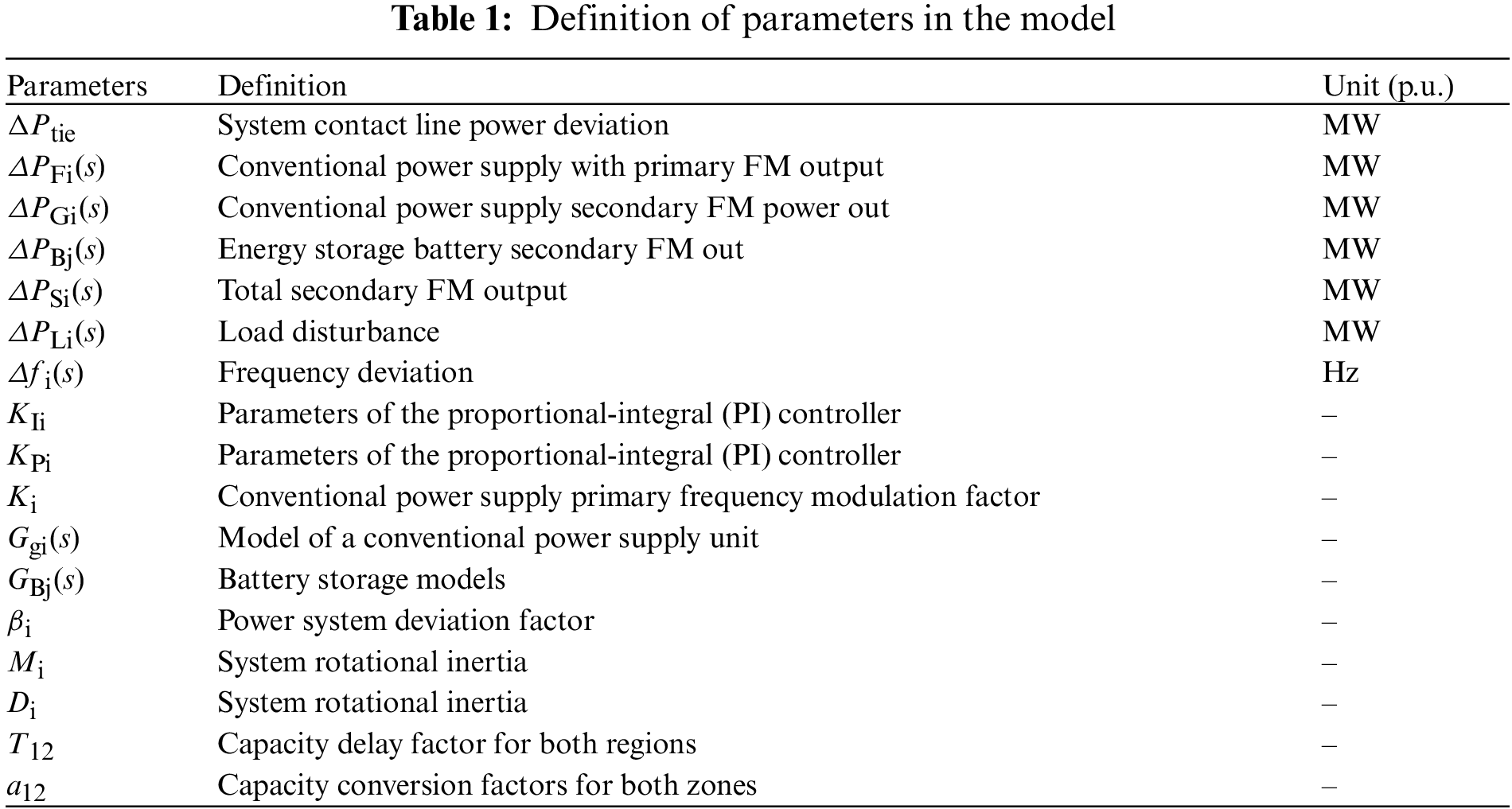
A typical two-region model load frequency control is studied as an example, and a two-region grid frequency dynamic response model with energy storage involved in secondary frequency regulation is established based on the regional equivalence approach [19]. The model is shown in Fig. 1, and the parameters in the model are defined as shown in Table 1.

Figure 1: Dynamic frequency response model for two regional grids
The model consists of a dispatch centre and a control unit for FM power supplies to enable primary and secondary FM. Area 1 is configured with 1 conventional unit and k BESS for FM, for a total of 1 + k FM power supplies, while area 2 is configured with only conventional units to achieve FM.
2.2 Models of Conventional Units and Battery Storage Systems
The conventional unit is a reheat-type thermal power unit and the model mainly consists of a governor and a reheat-type turbine. The reheat-type thermal power unit model is shown in Fig. 2a.

Figure 2: (a) Model of a reheat thermal power unit (b) Model of battery energy storage system
The functional expression for the model is as follows:
where,
The battery energy storage system is based on a first-order inertia model, which takes into account the charge state constraints of the system and can accurately simulate the dynamic characteristics of the energy storage system and the grid in the active exchange state. The model is shown in Fig. 2b.
In Fig. 2b: KB is the output gain, TB is the energy storage time constant, Sn is the rated capacity of the energy storage, SOC0 is the initial state of charge, and
The functional expression for the model is as follows:
where, GBj(s) is the transfer function of the battery storage system.
To prevent excessive power throughput range of the energy storage system, the range of SOC is constrained to be within the range of safe battery operation from the perspective of battery life, i.e.,
3 Strategies for the Allocation of ARR and ACE Signals
3.1 Control Structure of ACE and ARR Signals
The two modes of signal assignment for BESS participation in AGC FM are Area Control Requirement (ARR) based signal assignment and Area Control Deviation (ACE) based signal assignment [20]. The two signals can be converted by a PI controller, i.e., by integrating the Area Control Deviation (ACE) signal the Area Control Requirement (ARR) signal is obtained.
As shown in Figs. 3a and 3b, the participation factor α (taking values in the range 0.1–0.9) determines the power output allocation of the two FM sources (conventional units and energy storage batteries) to the ACE or ARR signals;

Figure 3: (a) ACE signal control structure (b) ARR signal control structure
Ignoring the FM Deadband and limiting constraints, from Fig. 3a we have
Of these, the models for reheat thermal units and energy storage batteries are
Rectifying Eqs. (6)–(10) yields the final expression for the ACE signal as
As can be seen from Eq. (7), the ACE signal is not delayed without a PI control link, so the system can respond quickly to transient changes in the signal.
Similarly, from Fig. 3b, it follows that:
Rectifying Eqs. (12)–(16) yields the final expression for the ACE signal as
From Eq. (12), it can be seen that there is a delayed effect on the ARR signal, which is better suited to respond to steady state changes.
3.2 Integrated Allocation Strategy for ACE and ARR Signals
From Eqs. (11) and (16), it can be seen that when the load perturbation

Figure 4: Difference curve between ACE and ARR signals
From Fig. 4, we can obtain a comprehensive allocation strategy for the system’s participation in the secondary FM for both signals, using whether the signal difference crosses the zero point as the timing for switching between the two modes.
(1) Signal difference before crossing the zero point
In the pre-FM period, when the ACE signal is gradually enhanced and larger than the ARR signal, it is conducive to the rapid recovery of the transient frequency deviation of the system, so the ACE control mode is adopted.
(2) Signal difference after crossing the zero point
In the middle and late stages of FM, the ACE signal is weakened while the ARR signal is gradually enhanced, at this time the ACE signal plays a suppressive role in the later FM, and the ARR control is conducive to improving the steady-state frequency deviation of the system, so the ARR control mode is adopted.
4 Two-Layer Fuzzy Control Strategy Based on a Two-Signal Distribution Model
4.1 Two-Level Fuzzy Control Process
A two-layer fuzzy control strategy based on an integrated distribution model of the ARR and ACE signals, which takes into account the FM demand and FM capability to modify the participation and depth of output of the energy storage battery.
The first layer fuzzy controller takes the frequency regulation demand of the grid as the purpose, takes the system frequency deviation and the power signal allocated to the FM unit in ACE (or ARR) mode as the input quantity, derives the connection between the total power response and the grid frequency difference demand in both modes, and determines the participation factor of the energy storage; the second layer fuzzy controller considers the energy storage’s frequency regulation capability based on the SOC state, takes the output of the first layer fuzzy control and The second layer fuzzy controller considers the energy storage’s frequency regulation capability based on the SOC state, and uses the output of the first layer fuzzy control and the real-time SOC of the energy storage as the input quantity to derive the connection between the real-time SOC of the energy storage and the participation factor, to determine the actual depth of the energy storage output.
The double-layer fuzzy control can take into account the frequency regulation capability of the energy storage system based on meeting the demand for grid frequency regulation, thus avoiding the phenomenon of battery overcharge and over-discharge. The double-layer fuzzy control process in dual-signal mode is shown in Fig. 5.

Figure 5: Double layer fuzzy control flow in dual signal mode
4.2 First-Level Fuzzy Control Strategy for Accounting for FM Demand
In the combined allocation mode of both ARR and ACE signals, the first layer of the fuzzy controller takes the system frequency deviation
The first level of the fuzzy controller is a two-dimensional control with the scale factors of the input quantities
where,
The Mamdani-type affiliation function is used.
The control rule of the first layer of the fuzzy controller is: when the system frequency deviation
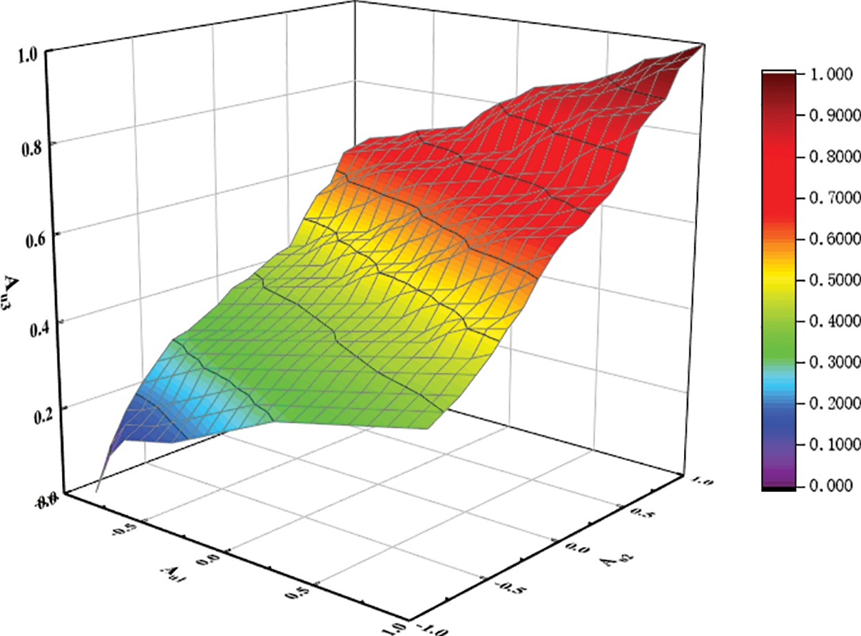
Figure 6: Three-dimensional surface view of Au1, Au2 and Au3
The output fuzzy quantity Au3(t) is anti-fuzzified using the area centre of gravity method to finally obtain the participation factor α(t) as shown in Eq. (18).
where, u11, u12 and u13 are the values of
4.3 Second Layer Fuzzy Control Strategy with FM Capability
In the combined distribution mode of both ARR and ACE signals, the second layer of the fuzzy controller takes into account the FM capability of the battery and uses the participation factor α of the energy storage system and the real-time battery charge state quantity QSOC as inputs to determine the outgoing depth of energy storage Pout−1 (or Pout−2).
The second layer of the fuzzy controller is the same two-dimensional control, with the scale factors for the input quantities α and QSOC and the scale factors k21, k22 and k23 for the output quantity Pout−1 (or Pout−2) as shown in Eq. (19).
α(t) and QSOC(t) are the two inputs of the fuzzy controller, whose theoretical domain range is [0,1]; Pout−1(t) (or Pout−2(t)) is the output of the fuzzy controller, whose theoretical domain range is [−1,1]. The fuzzy subsets are taken as seven subsets such as NB (negative large), NM (negative medium), NS (negative small), ZO (zero), PS (positive small), PM (positive medium), and PB (positive large).
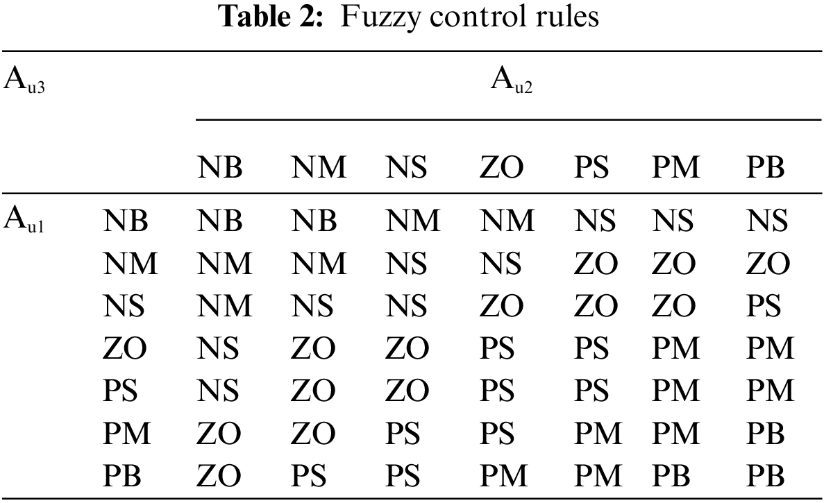
The control rule of the second layer of the fuzzy controller is: when the real-time charge state of energy storage battery QSOC is too large or too small, to prevent the energy storage system from being damaged by overcharge and over-discharge, the power out the depth of energy storage Pout−1 (or Pout−2) should be appropriately reduced as the participation factor α of the energy storage system increases; when the real-time charge state of energy storage battery QSOC is within the safe range, the power out the depth of energy storage Pout−1 (or Pout−2) should be appropriately increased as the participation factor α of the energy storage system increases to ensure the demand of system frequency regulation. Second, the values of the affiliation functions for α(t), QSOC(t) and Pout−1(t) (or Pout−2(t)) are defined as Bu1(t), Bu2(t) and Bu3(t), respectively. The final relationship between input Bu1(t), Bu2(t) and output Bu3(t) can be obtained as shown in Fig. 7, and the fuzzy control rule table is shown in Table 3.

Figure 7: Three-dimensional surface view of Bu1, Bu2 and Bu3
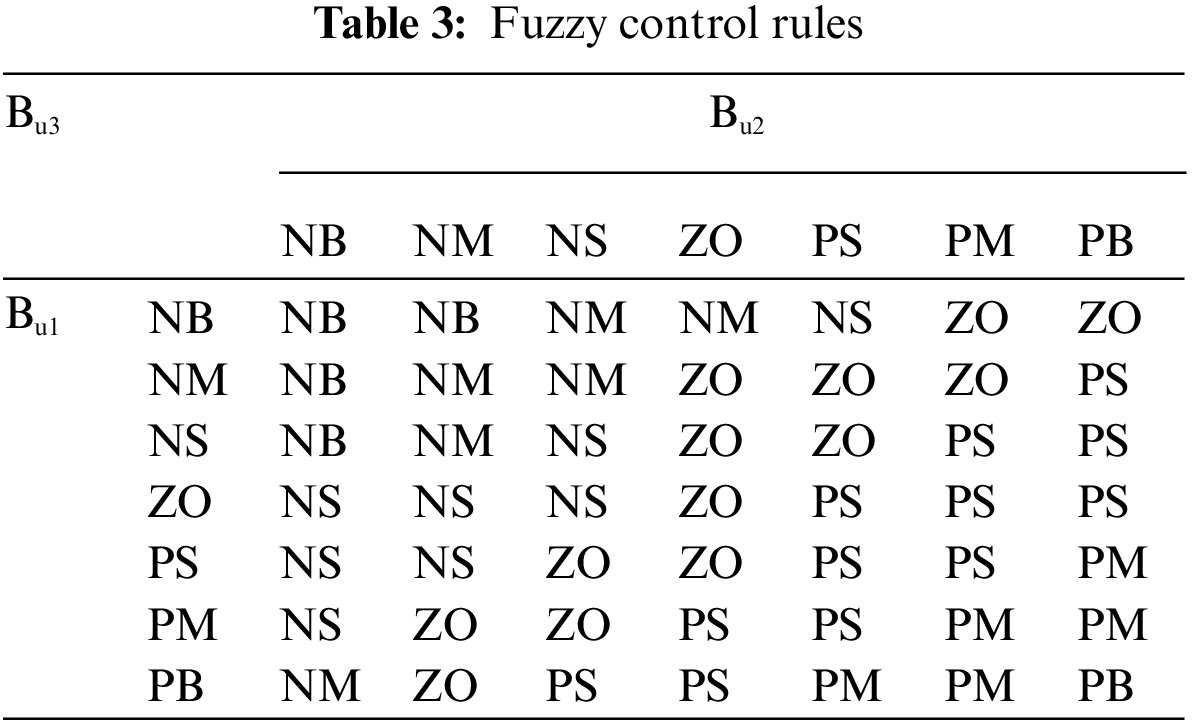
The output fuzzy quantity Bu3(t) is anti-fuzzified using the area centre of gravity method, resulting in the output depth Pout−1 (t) (or Pout−2 (t)) as shown in Eq. (20).
where, u21, u22 and u23 are the values of α(t), QSOC(t) and Pout−1(t) (or Pout−2(t)) respectively after fuzzy quantization, and Bu1(t), Bu2(t) and Bu3(t) are the values of α(t), QSOC(t) and Pout−1(t) (or Pout−2(t)) respectively after substitution.
5 Simulation Experiments and Analysis of Results
5.1 Simulation Parameters and Evaluation Systems
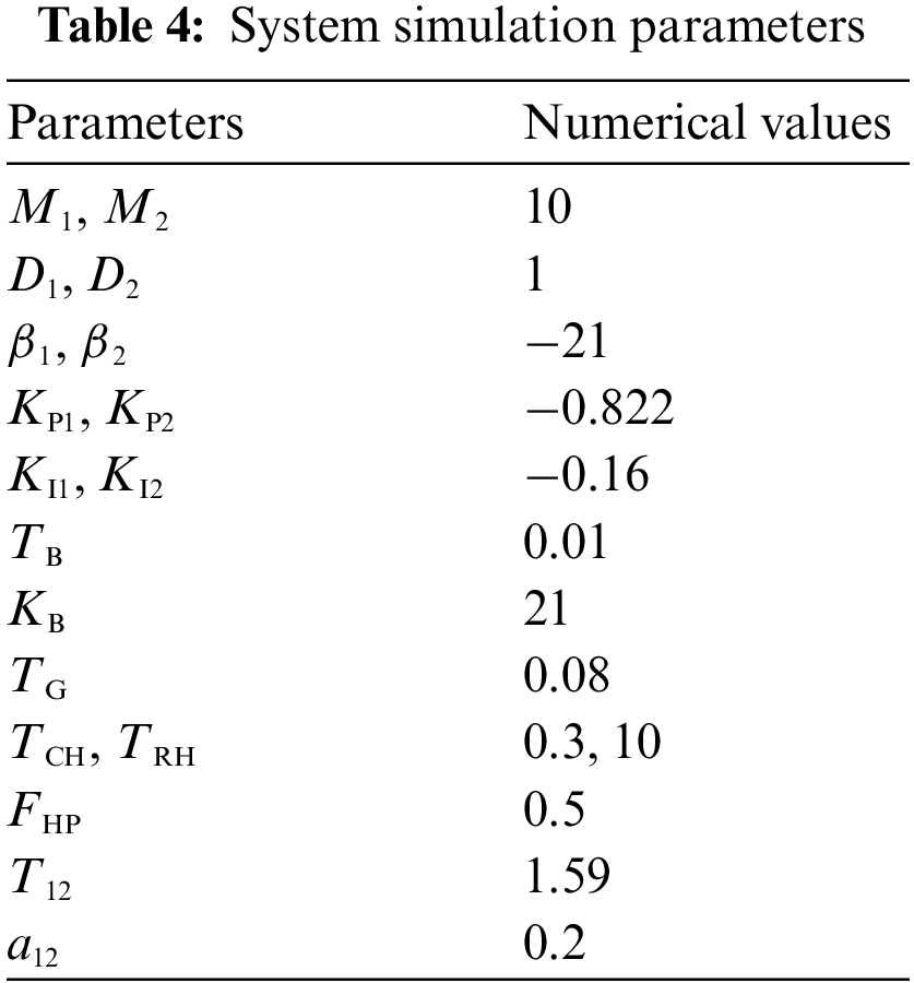
The equivalent model of a typical grid in two regions with energy storage participating in secondary frequency regulation shown in Fig. 1 is simulated in the Matlab/Simulink platform, with a conventional frequency regulation unit using a reheated thermal power unit rated at 750 MW (with a climbing rate of 25 MW/min) and energy storage with rated power and capacity of 10.5 MW and 1.5 MW/h, respectively. The rated frequency of 50 Hz and the maximum rated capacity of the unit is used as the reference value for the standardization. Two typical operating conditions, step disturbance and continuous disturbance are designed and simulated to test the effectiveness of the proposed control strategy (Scheme 3) against the fuzzy control without energy storage (Scheme 2) and without energy storage (Scheme 1). The system simulation parameters are shown in Table 4 [21,22].
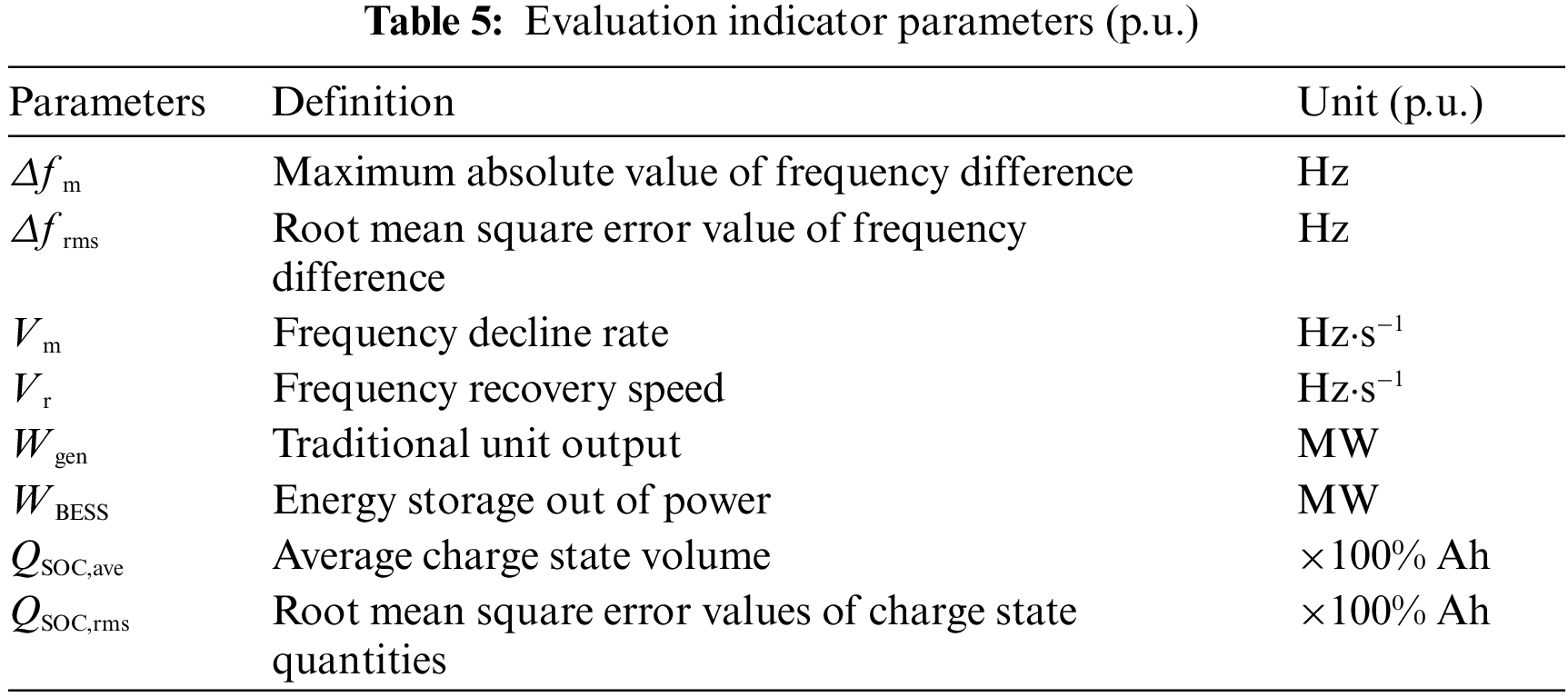
To more intuitively compare the effects of the three schemes, a corresponding evaluation system is established based on the frequency regulation effect, power output and charge maintenance level. The smaller
In regions 1 and 2, step perturbations of 0.015 and 0.01 are added to
Fig. 8a shows the curves of frequency deviation of the system after adding the step disturbance. From the picture, it can be seen that all three schemes can adjust the frequency deviation without a difference, but compared with Scheme 1 and Scheme 2, Scheme 3 is more sensitive to the disturbance and can restore the frequency deviation to 0 in a shorter time, and at the same time, the fluctuation of frequency deviation can be controlled in a smaller range during the recovery process. Fig. 8b shows the output change curve of the traditional unit after adding the step disturbance. From the picture, it can be seen that the traditional unit is always in the output state in the process of frequency regulation, and compared with Scheme 2, the traditional unit in Scheme 3 has less output in the process of frequency regulation, indicating that the conventional unit is more suitable for regulating the steady-state frequency deviation for a long time. Fig. 8c shows the power change curve of the energy storage unit after adding the step disturbance, and it can be seen from the picture that the energy storage unit is discharged and then charged until the end of frequency regulation, and then no more power is produced. Compared with Scheme 2, the energy storage unit in Scheme 3 has a smaller power output and a shorter power output time during the frequency regulation process. Fig. 8d shows the change curve of the charge state of the storage cell after adding the step disturbance. From the picture, it can be seen that the initial charge state of the storage unit is 0.5, and the charge state will gradually recover to the initial value after the end of FM. Compared with Scheme 2, the storage unit in Scheme 3 fluctuates less and recovers faster in the process of maintaining the charge level.
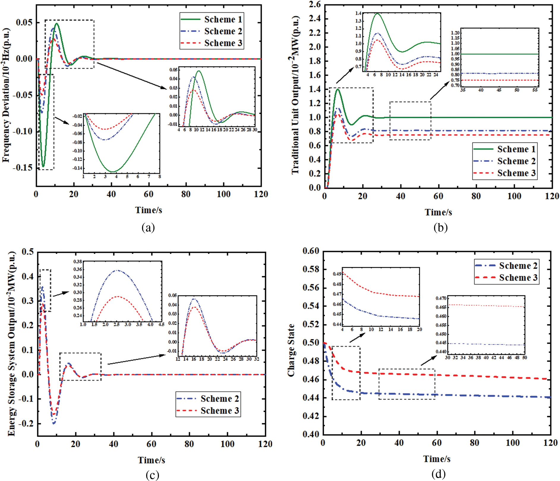
Figure 8: (a) Comparison of frequency deviations (b) Comparison of traditional unit output (c) Comparison of energy storage system output (d) Comparison of charge states
With the addition of continuous perturbation in region 1 as shown in Fig. 9a. To better verify the effectiveness of the method in this paper based on the evaluation system, the change curves of frequency deviation, traditional unit output, battery storage output and battery charge state of the three schemes under continuous perturbation is used for comparison.

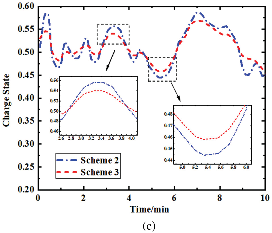
Figure 9: (a) Continuous load disturbance (b) Comparison of frequency deviations (c) Comparison of traditional unit output (d) Comparison of energy storage system output (e) Comparison of charge states
Fig. 9b shows the change curve of frequency deviation of the system after adding continuous perturbation. From the picture, it can be seen that all three schemes can regulate the frequency deviation after adding continuous perturbation but compared with Scheme 1 and Scheme 2, Scheme 3 can control the frequency deviation within a smaller range in a shorter time, and at the same time, it can control the fluctuation of frequency deviation within a smaller range during the recovery process. Fig. 9c shows the output change curve of the traditional unit after adding the continuous disturbance, and it can be seen from the picture that the traditional unit continues to produce less output in the process of frequency regulation, compared with Scheme 2 in Scheme 3. Fig. 9d shows the change curve of the energy storage unit after adding continuous disturbance, from the picture, it can be seen that the energy storage unit is continuously charged and discharged during the process of frequency regulation, compared with Scheme 2, the energy storage unit in Scheme 3 is less charged and discharged during the process of charging and discharging and the time of discharging is shorter. Fig. 9e shows the change curve of the charge state of the storage battery after adding the continuous disturbance, from the picture, it can be seen that the initial charge state of the storage unit is 0.5, and the charge state of the storage increases when charging and decreases when discharging. Compared with Scheme 2, the storage unit in Scheme 3 fluctuates less and recovers faster in the process of maintaining the charge level.
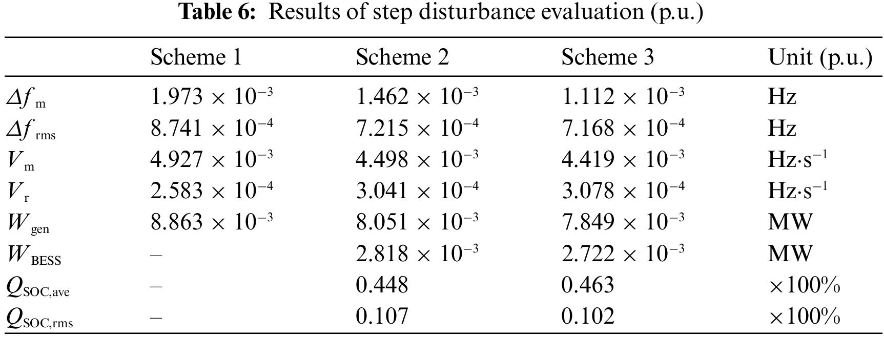
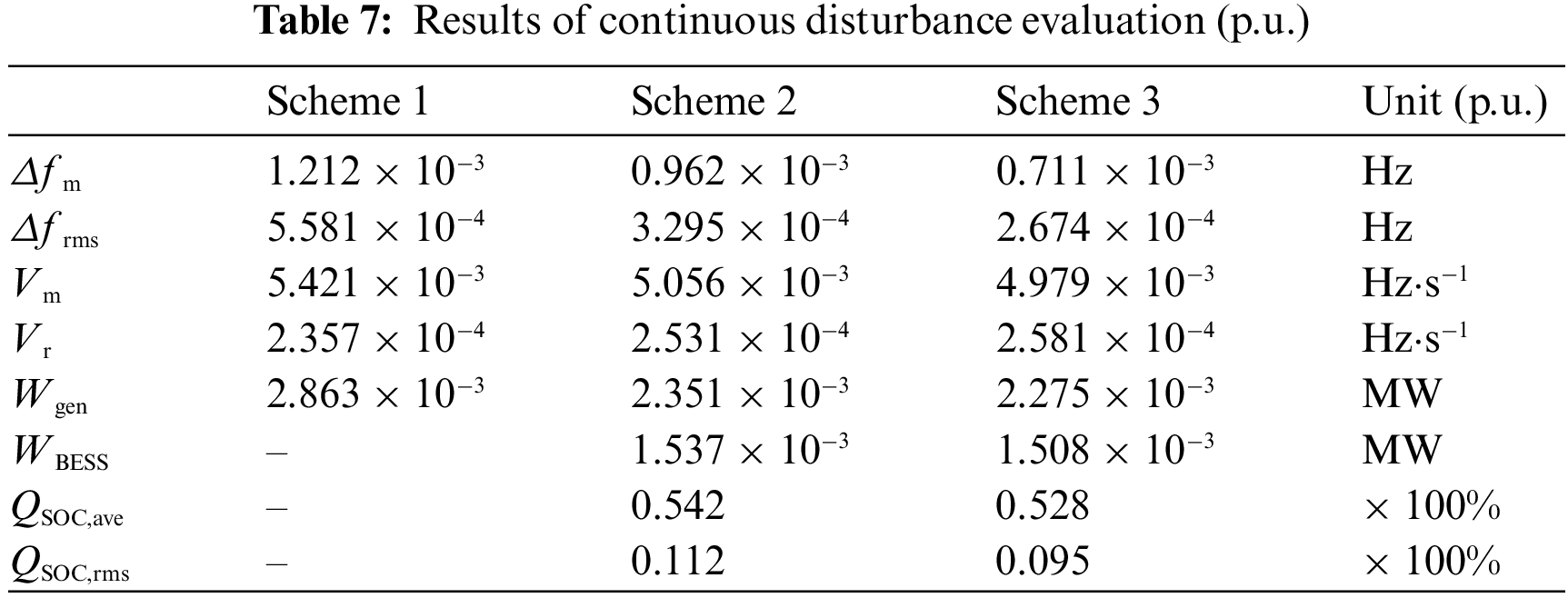
The simulation results are analysed in terms of frequency modulation effect, power output and charge maintenance level. The evaluation results under the standardized values are shown in Tables 6 and 7.
(1) FM effects
From Tables 6 and 7 and Figs. 8a and 9b, it can be seen that
(2) Power output
From Tables 6 and 7 and Figs. 8c and 9d, it is clear that the traditional unit in Scheme 3 has 12.91% and 2.57% lower output under step perturbation than Schemes 1 and 2, and the traditional unit in Scheme 3 has 25.85% and 3.34% lower output under continuous perturbation than Schemes 1 and 2. Therefore, the traditional unit in scenario 3 has the highest utilization rate.
From Tables 6 and 7 and Figs. 8b and 9c, it is clear that the energy storage unit in Scheme 3 has a 3.52% lower output under step disturbance than Scheme 2, and the energy storage unit in Scheme 3 has a lower and 1.92% lower output under continuous disturbance than Scheme 2. Therefore, the energy storage unit in Scheme 3 has the highest utilization rate.
(3) Charge maintenance level
From Tables 6 and 7 and Figs. 8d and 9e, it is clear that compared to Scheme 2, the QSOC,ave in Scheme 3 is closer to the initial charge state under both step perturbation and continuous perturbation, and the QSOC,rms in Scheme 3 is also smaller. Therefore, the charge maintenance level in Scheme 3 is the best.
In this paper, a double-layer fuzzy control strategy is proposed for the participation of multiple energy storage battery systems in frequency regulation, taking into account the grid frequency regulation demand and battery charge state. Its advantages are as follows: (1) The dual-signal assignment strategy solves the problem of poor coordination of FM units caused by not considering the characteristics of ACE signal and ARR signal in the signal assignment in the past by timely conversion of two FM signals. (2) Introducing the system frequency deviation and battery charge state into the input part of the two-layer fuzzy controller separately can control the frequency deviation within a smaller range in a shorter time, while reducing the fluctuation of the battery charge state. Simulation results show that compared with Scheme 2 and Scheme 3, the decrease rate of frequency can be reduced by 1.55%~11.49%, the recovery rate of frequency can be increased by 1.51%~19.16%, and the mean value of the charge state is closer to the initial value. (3) The double-layer fuzzy controller can reduce the output of traditional units by 2.57%~25.85% and the output of energy storage units by 1.92%~3.52% through the progressive control of the unit participation as well as the depth of output, which effectively improves the utilization rate of the units and reduces the cost of output.
Funding Statement: This research was funded by the Gansu Provincial Science and Technology Information Disclosure System Project (21ZD8JA001) and Tianyou Innovation Team of Lanzhou Jiaotong University (TY202009).
Conflicts of Interest: The authors declare that they have no conflicts of interest to report regarding the present study.
References
1. Shi, Y. Y., Xu, B. L., Wang, G. D. (2018). Using battery storage for peakshaving and frequency regulation: Joint optimization for superlineargains. IEEE Transactions on Power Systems, 33(3), 2882–2894. https://doi.org/10.1109/TPWRS.2017.2749512 [Google Scholar] [CrossRef]
2. Tan, J., Zhang, Y. (2017). Coordinated control strategy of a battery energystorage system to support a wind power plant providing multi-times-cale frequency ancillary services. IEEE Transactions on Sustainable Energy, 8(3), 1140–1153. https://doi.org/10.1109/TSTE.2017.2663334 [Google Scholar] [CrossRef]
3. Megel, O., Liu, T., Hill, D. J. (2018). Distributed secondary frequency control algorithm considering storage efficiency. IEEE Transactions on Smart Grid, 9(6), 6214–6228. https://doi.org/10.1109/TSG.2017.2706979 [Google Scholar] [CrossRef]
4. Tang, J. (2019). Research on capacity allocation and control strategy for energy storage battery participation in secondary frequency regulation of power grid (Master’s Thesis). School of Electrical and Information Engineering, Hunan University, China (in Chinese). [Google Scholar]
5. Han, X. (2021). Research on frequency control strategy of grid-side battery energy storage system (Master’s Thesis). School of Electrical and Electronic Engineering, North China Electric Power University, China (in Chinese). [Google Scholar]
6. Wu, Y. L., Sun, Y. Z., Xu, A. (2012). A coordinated load-frequency control system for interconnected power systems based on multivariate generalized prediction theory. Journal of Electrical Engineering Technology, 27(9), 101–107. [Google Scholar]
7. Makarov, Y. V., Du, P., Kintner-Meyer, M. C., Jin, C., Illian, H. F. (2012). Sizing energy storage to accommodate high penetration of variable energy resources. IEEE Transactions on Sustainable Energy, 3(1), 34–40. [Google Scholar]
8. Hu, Z. C., Xie, X., Zhang, F. (2014). Research on automatic power generation control strategy with the participation of energy storage resources. Chinese Journal of Electrical Engineering, 34(29), 5080–5087. [Google Scholar]
9. Jin, C. L., Lu, N., Lu, S. (2014). A coordinating algorithm for dispatching regulation services between slow and fast power regulating resources. IEEE Transactions on Smart Grid, 5(2), 1043–1050. https://doi.org/10.1109/TSG.2013.2277974 [Google Scholar] [CrossRef]
10. Bao, B., Jia, L. M., Jiang, J. C. (2015). Research on auxiliary frequency control strategy for electric vehicles with mobile energy storage. Journal of Electrical Engineering Technology, 30(11), 115–126. [Google Scholar]
11. Tabrizi, M., Sahni, M. (2014). Dynamic available AGC based approach for enhancing utility scale energy storage performance. IEEE Transactions on Smart Grid, 5(2), 1070–1078. https://doi.org/10.1109/TSG.2013.2289380 [Google Scholar] [CrossRef]
12. Lv, L. X., Chen, S. H., Zhang, X. B., Pang, T., Huang, C. X. (2021). A secondary frequency control strategy for power systems considering the consistency of scaled battery energy storage SOC. Thermodynamics, 50(7), 108–117. https://doi.org/10.19666/j.rlfd.202012296 [Google Scholar] [CrossRef]
13. Zhou, W. Z. (2021). Research on state estimation-based frequency control strategy for energy storage battery-assisted power grid (Master’s Thesis). School of Electrical and Information Engineering, Changsha University of Technology, China (in Chinese). [Google Scholar]
14. Li, X. R., Huang, J. Y., Chen, Y. Y. (2017). Sensitivity analysis-based control strategy for energy storage battery participation in secondary frequency regulation. Journal of Electrical Engineering Technology, 32(12), 224–233. [Google Scholar]
15. Hu, Z. C., Xie, X., Zhang, F. (2014). Research on the control strategy of automatic power generation with the participation of energy storage resources. Chinese Journal of Electrical Engineering, 34(29), 5080–5087. [Google Scholar]
16. Liao, S. B., Liu, K. P., Le, J. (2019). Collaborative control strategy for cross-region AGC units based on two-layer model prediction structure. Chinese Journal of Electrical Engineering, 39(16), 4674–4685. [Google Scholar]
17. Zhou, Y. J. (2018). Research on the fuzzy control strategy of energy storage battery participation in AGC secondary frequency regulation (Master’s Thesis). School of Electrical and Information Engineering, Hunan University, China (in Chinese). [Google Scholar]
18. Zhang, S. P., Dong, S. F., Xu, C. S., Han, R. J., Shou, T. et al. (2020). A two-layer control strategy for large-scale energy storage participation in grid frequency regulation. Power System Automation, 44(19), 55–62. [Google Scholar]
19. Cao, X., Zhao, N. A. (2022). Cooperative management strategy for battery energy storage system providing enhanced frequency response. Energy Reports, 8, 120–128. https://doi.org/10.1016/j.egyr.2021.11.092 [Google Scholar] [CrossRef]
20. Zhang, S. Q., Yuan, B., Xu, Q. S. (2019). Optimal control policy of grid secondary frequency regulation with the participation of scaled energy storage. Power Automation Equipment, 39(5), 82–88, 95. [Google Scholar]
21. Li, R., Li, X. R., Tan, Z. X., Huang, J. Y. (2018). An integrated control strategy considering energy storage battery participation in secondary frequency regulation. Power System Automation, 42(8), 74–82. [Google Scholar]
22. Chang, K., Zhou, T., Zhang, H., Liu, S. F. (2022). Energy storage battery participation in grid secondary frequency regulation parameter optimization. Electronic Design Engineering, 30(2), 64–68.https://doi.org/10.14022/j.issn1674-6236.2022.02.014 [Google Scholar] [CrossRef]
Cite This Article
 Copyright © 2023 The Author(s). Published by Tech Science Press.
This work is licensed under a Creative Commons Attribution 4.0 International License , which permits unrestricted use, distribution, and reproduction in any medium, provided the original work is properly cited.
 Downloads
 Citation Tools