
 Submit a Paper
 Propose a Special lssue
 Open Access
ARTICLE

Virtual Synchronous Generator Adaptive Control of Energy Storage Power Station Based on Physical Constraints
1 School of New Energy and Power Engineering, Lanzhou Jiaotong University, Lanzhou, 730070, China
2 State Grid Gansu Electric Power Research Institute, Lanzhou, 730070, China
* Corresponding Author: Haiying Dong. Email:
Energy Engineering 2023, 120(6), 1401-1420. https://doi.org/10.32604/ee.2023.027365
Received 26 October 2022; Accepted 16 December 2022; Issue published 03 April 2023
 View Full Text
 Download PDF
Abstract
The virtual synchronous generator (VSG) can simulate synchronous machine’s operation mechanism in the control link of an energy storage converter, so that an electrochemical energy storage power station has the ability to actively support the power grid, from passive regulation to active support. Since energy storage is an important physical basis for realizing the inertia and damping characteristics in VSG control, energy storage constraints of the physical characteristics on the system control parameters are analyzed to provide a basis for the system parameter tuning. In a classic VSG control, its virtual inertia and damping coefficient remain unchanged. When the grid load changes greatly, the constant control strategy most likely result in the grid frequency deviation beyond the stable operation standard limitations. To solve this problem, a comprehensive control strategy considering electrified wire netting demand and energy storage unit state of charge (SOC) is proposed, and an adaptive optimization method of VSG parameters under different SOC is given. The energy storage battery can maintain a safe working state at any time and be smoothly disconnected, which can effectively improve the output frequency performance of energy storage system. Simulation results further demonstrated the effectiveness of the VSG control theoretical analysis.Keywords
Since the goals of carbon peaking and carbon neutrality and new-energy-oriented electric systems have been put forward, the power industry has established a new power system that treats renewable energy as the principal part of the reform goal in China. Since renewable energy’s output is uncertain, the change of the power system’s main source will further reduce its stability. The introduction of energy storage units into the power system shall not only improve the utilization rate of new energy but also actively carry out peak shaving and frequency modulation [1–4].
With the innovation of battery technology, large-capacity centralized energy storage power stations continue to be used as power sources to provide energy support for the grid [5–7], which are included in the grid-connected operation and auxiliary service management. Li et al. [8,9] concluded that the main functions of the energy storage power station are peak load regulation, long-term power supply, primary frequency regulation, stabilizing power fluctuation, standby power and tracking planned power generation.
According to Zhong [10], nowadays distributed generation system with the power electronic converter as the interface lacks the inertia and damping of the traditional synchronous generator (SG). In the wake of increasing new energy penetration rate and withdrawal of corresponding SGs, the system inertia level and primary frequency modulation resources gradually decrease. Under the disturbance of the same intensity, Delille et al. [11] had concluded that the reduction of the inertia level will worsen the maximum frequency offset and the maximum frequency change rate, so the power system is more vulnerable to power fluctuations and system failures.
Over the last decade, Zhong et al. [12,13] proposed a virtual synchronous generator (VSG), which gives power electronic converter of energy storage power station capacity to sustain inertia and damping of the electrified wire netting by imitating SG, and enhance its anti-interference ability, give a pledge to electrical grids’ safe and steady operation. In the distributed system described by Torres et al. [14], the converter takes an adaptive control of VSG, and relevant adaptive control rules are designed to optimize the inertia and damping coefficients to reduce the output power of energy storage devices. In addition, the anti-jamming capability of the system can also get improved by using a newly designed equation about frequency-dependent coefficient [15,16]. Such expositions are unsatisfactory because the above adaptive VSG control strategies need to accurately model the converter to get the best control.
On the other hand, fuzzy control uses a language method, which is easy to carry out human-computer interaction. The precise mathematical model does not need to be established in the control process. It has strong robustness and is suitable for solving the problems of nonlinearity, strong coupling, time-varying and delay in process control [17,18]. Ebrahimi et al. [19–23] used fuzzy adaptive VSG control to reduce frequency fluctuation.
Hu et al. [24] expound the essence of inertia in an energy storage system with the theory that inertia is a form of energy, and an equivalent inertia calculation method for a given energy storage system is came up. On this basis, Yuan et al. [25] established the physical constraints of the energy storage side on the virtual synchronous machine plus its operating boundary.
Chen et al. [26] proposed an adaptive control strategy to achieve SOC balance between several VSGs based on paralleled energy storage systems in a decentralized manner. With the proposed method, no matter what the difference between VSGs’ initial values and interference is, the SOC balance can be easily achieved without a communication network. The above research fails to consider that when the energy storage system shuts down at the minimum SOC, the output power of VSG will be greatly reduced in a short time, which will seriously affect the power grid.
To sum up, a VSG adaptive control strategy considering SOC feedback of energy storage battery is proposed. Firstly, this paper lists physical constraints based on the energy storage side, thus given VSG’s inertia, output power and change rate of the power have corresponding value ranges. Then divides the VSG parameter settings of inertia, damping, active and reactive reference values into three groups. Different control strategies are adopted under different SOC to realize parameter adaptive control, so as to smooth power fluctuations when VSG is off-grid while maintaining a certain frequency modulation performance. Finally, through the MATLAB platform, the validity of the above integrated control strategy is verified by simulation.
2 VSG Control of Energy Storage Power Station
Based on the classical second-order model of SG with polar logarithm of 1, the second-order VSG model is established. In order to meet the seamless switching and smooth transition between isolated island operation and grid connected operation of energy storage power station, a voltage source VSG mode is adopted in this paper, where Fig. 1 is its topology diagram, where mechanical and electromagnetic equations can broadly be defined as follows:
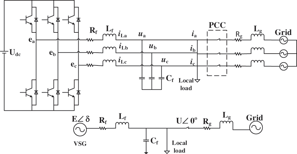
Figure 1: Configuration of the VSG
In Eq. (1): Pm is the virtual machine power; Pe is the output active power; J is virtual inertia;
In this paper, the VSG control is primarily composed of active frequency control and reactive voltage control. Pm is made up of active power given reference value Pref and frequency deviation response command value:
where Kf is the active frequency modulation coefficient of VSG.
VSG’s transient potential E consists of three parts: E0, the no-load potential, represents the machine terminal voltage when the converter runs off-grid without load; the machine terminal voltage regulation amount and the reactive power regulation amount. In summary, the given output voltage amplitude expression is:
In Eq. (3), Kv is the voltage regulation coefficient of the VSG; Uref means the rated value of the machine terminal voltage; U is the converter output port line voltage; Kq represents the reactive power regulation coefficient of the VSG; Qref indicates system’s reactive power command, Qe indicates instantaneous reactive power output of machine terminal. From Eqs. (1)–(3), the VSG control scheme adopted in this paper is shown in Fig. 2.
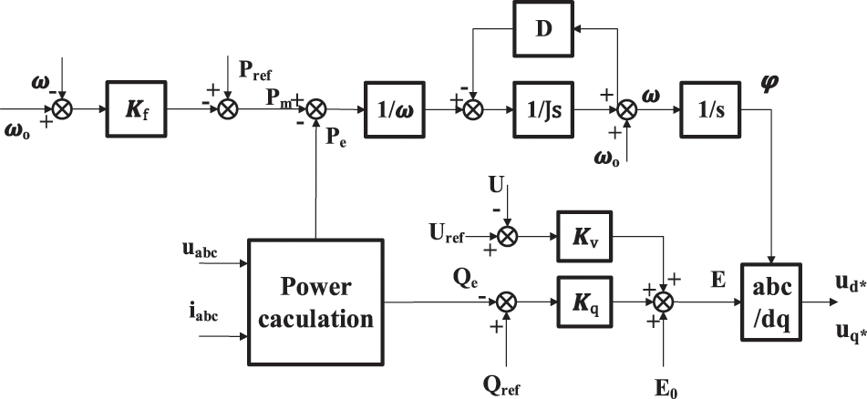
Figure 2: Configuration of VSG control
The output modulation voltage is controlled by an inner loop of inductor current and an outer loop of capacitor voltage, and the output 6-pulse PWM signal is modulated by Space Vector Pulse Width Modulation (SVPWM), which is shown in Fig. 3. In the figure, Lv represents virtual impedance.
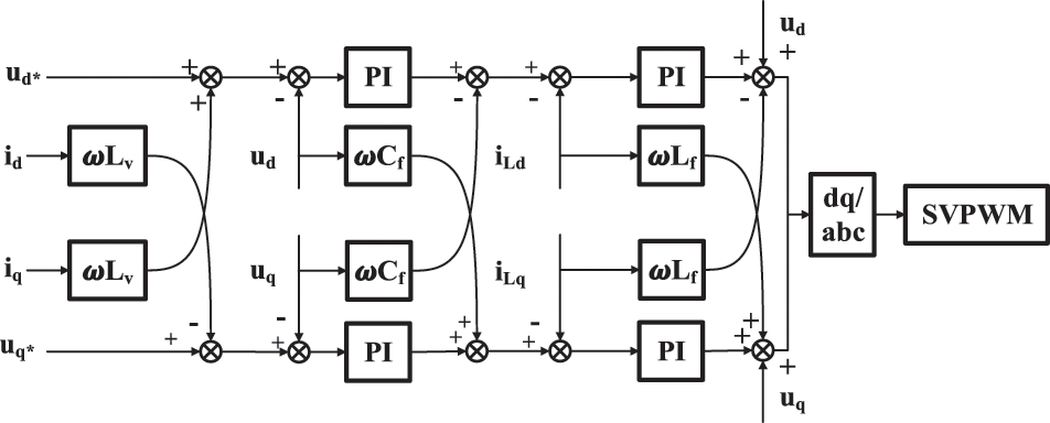
Figure 3: Voltage and current double closed-loop control
3 Physical Constraints for Safe and Stable Operation
In practical energy storage projects, the storage capacity of VSG is usually fixed, and its size is limited by factors such as environment and investment. Therefore, to ensure that the inertia and damping of the VSG are always subject to the energy storage during the setting process and the corresponding response characteristics of the system during the transient process, the corresponding physical constraints index of the VSG are designed, namely, SOC, the charge rate and discharge rate, and power change rate.
3.1 Working Characteristics of Storage Batteries
Generally, the residual power of the energy storage unit is represented by SOC. The maximum capacity of a fully charged battery is SCN, define SOC0 as the initial SOC when the energy storage converter starts to work, then the instantaneous charging and discharging current is defined as i(t), the expression of SOC is as follows:
V0 is defined as the initial working voltage of the battery, and the initial state of charge SOC0 is as follows:
In practical terms, a battery has a certain normal working range, as shown in Eq. (5). In order to avoid deep discharge and overcharge that accelerate the battery’s life loss, when the SOC of the battery is less than SOCmin, the minimum value of SOC, the battery shall only be charged; when the SOC of the battery is greater than SOCmax, the maximum value of SOC, the battery should not be overcharged. As shown in Fig. 4, when the lithium iron phosphate battery is discharged under the same temperature and constant current, the characteristic curve between the normal working regions can be approximately regarded as one straight line whose slope value is k, define the charge cut-off voltage as Vmax when SOC = SOCmax, and define the discharge cut-off voltage as Vmin when SOC = SOCmin.
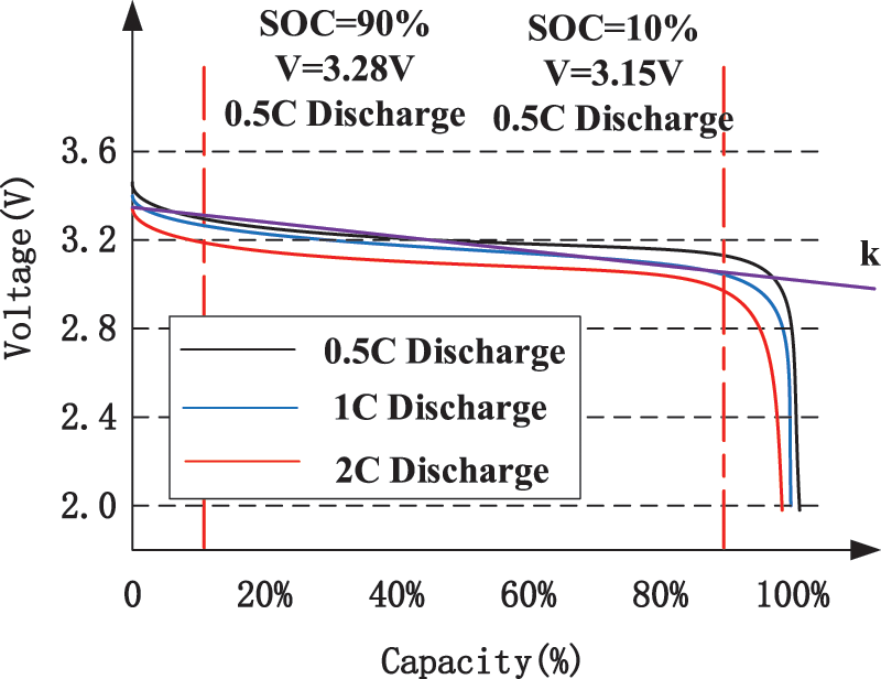
Figure 4: Lithium iron phosphate battery (50 Ah) discharge curve
The evaluation method for the battery’s charging or discharging rate is shown in the following Eq. (7), and its unit is C.
The charging and discharging rate is a characteristic quantity to describe the energy storage battery’s charging and discharging speed. During constant current discharge, the electric energy output by the battery with different discharge rates is different. The greater the current, the smaller the output capacity. The battery’s maximum charge (discharge) rate is related to the physical properties of its own electrolyte. Excessive charge (discharge) rate will shorten the design working life of energy storage units. For better protection, the charging and discharging rates are set with maximum values
In addition, the charging and discharging power Pch and Pdis are respectively used to indicate the charging and discharging capacity that the battery can generate:
It should be noted that Vmin and Vmax are the cut-off voltage of the battery when working at the maximum charge (discharge) rate.
The power change rate is an important factor that affects the dynamic response performance of VSG system or the life of the energy storage device. When the load power of the power grid changes, the VSG shall compensate for the fluctuation, therefore its output power changes accordingly. Especially when the power change rate is too big, it will lead to the chemical reaction inside the battery fail to keep up, leading to partial overcharge or partial overdischarge inside the battery.
where βch and βdis represent the limit values of the change rate of battery charge, discharge power. To avoid accelerated degradation of battery performance under severe dynamic loading conditions, the battery power change rate is usually limited to 2%~20% of the maximum output power. As for the whole energy storage power station, its power limit and power change rate are limited to the installed capacity, and the maximum limit of 1-min active power change is 10% of the installed capacity.
3.2 Physical Constraints of Energy Storage Side
As the energy supply end of the energy storage power station, the battery’s performance finally determines the frequency response capability of VSG. The energy storage battery must always be kept in a normal working state so as to prolong its service life and avoid fire accidents caused by overheating. The theory limits the output power from SOC, discharge power, and change rate of discharge power, respectively.
Battery’s SOC constraint: According to Eq. (5), when the battery is not within the normal operating range, the energy storage converter shall actively disconnect the corresponding batteries to ensure that those batteries will not discharge excessively.
Battery’s discharge power constraint: Due to the limitation of the electrochemical reaction, usually battery’s discharge power is supposed to be limited within a suitable range, which is shown in Eq. (10). When the discharge power of the energy storage converter exceeds this limit, the VSG shall make Pm equal to the rated discharge power of the battery.
Battery’s change rate of discharge power constraint: as shown in Eq. (11). When the discharge power change rate exceeds this limit, the energy storage converter shall reduce the change amount of Pm until the constraints conditions are met.
Virtually, the inertia and damping characteristics of VSG are controlled by energy storage units, so the setting of virtual inertia J and damping coefficient D should also take the constraints of the discharge characteristics of the battery into consideration. We need hardly say that the inertia of the SG is derived from the mechanical energy in the rotor. Likewise, the inertia of the VSG is actually derived from the potential energy in the battery. In Eq. (12), Wk means the rotor rotational kinetic energy of SG; Evsg is the equivalent rotor kinetic energy of VSG; EC indicates the electric potential energy of the battery.
While the battery is discharging, it can not be fully discharged. Most part of its potential energy is used to support VSG normal output and frequency modulation, and the rest part is used to maintain the SOC of the battery. Therefore, when the law of conservation of energy as (12) shows and, hence, the energy used to maintain the lowest SOC needs to be deducted from the potential energy, as shown in Eq. (13).
Then, the next step is to obtain the battery’s equivalent inertia Jeq considering constraints of SOC and maximum discharge rate:
where Ceq is defined as the equivalent capacitance value of the battery under the rated conditions according to Eq. (15). In Eq. (15), UCN is the battery’s rated voltage, ICN is its rated current, and TCN is its rated discharge time.
4 Improved VSG Control Strategy Based on SOC Feedback
During the normal shutdown of the conventional generator set, the load shall be gradually removed, the load switch shall be disconnected, and the generator shall be shut down after running at idle speed for 3–5 min. Since the capacity of the energy storage batteries is still very limited compared to the large grid, the energy storage power station will temporarily stop providing power grid support and frequency modulation services to prevent its energy storage units from discharging beyond the limit especially after one battery pack have been discharging to the power grid for a long period of time. Due to the discharge characteristics of the electric energy storage system, once the energy storage battery is disconnected from the energy storage converter, the energy storage converter AC output shall drop sharply, along with grid frequency becoming unstable, and VSG frequency modulation completely loses its energy support, which is a huge disturbance to the grid.
4.1 Improved VSG Control Structure
When the SOC exceeds the energy storage battery’s specified reasonable range, the battery must exit the frequency modulation process and use other battery packs to adjust the system frequency. It can be considered to appropriately reduce the battery output when the SOC is really low (still in the normal range) to form a variable VSG regulation strategy based on SOC, as shown in Fig. 5a.
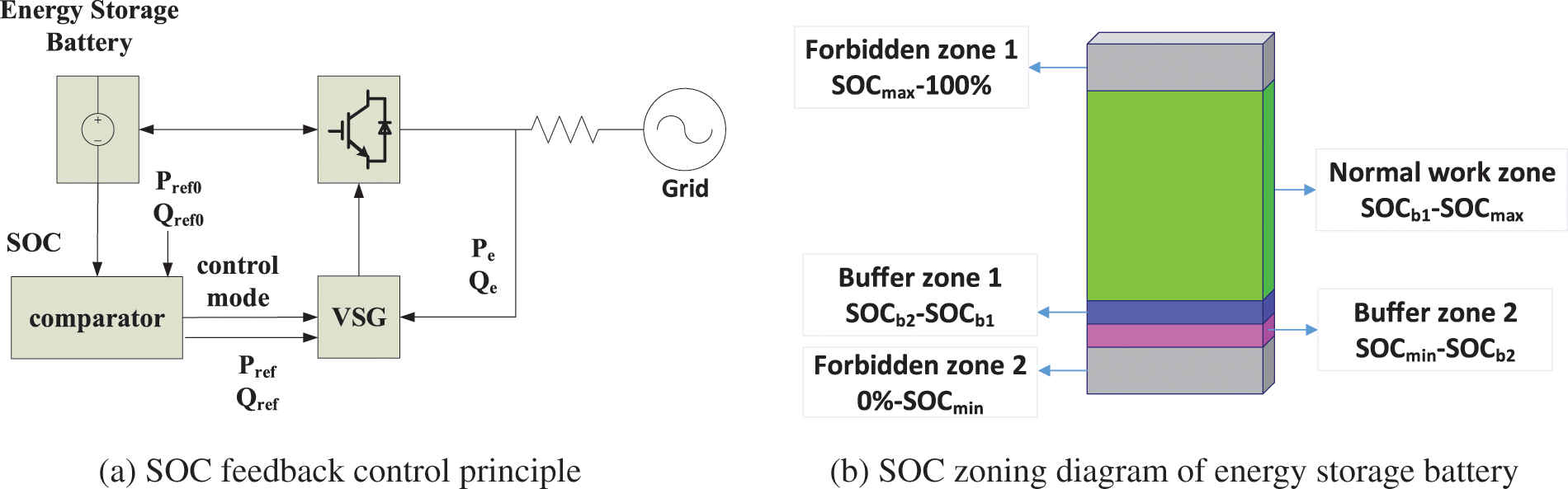
Figure 5: Improved VSG control structure
Pref0 and Qref0 are the active and reactive output power commands received by the VSG during grid connection operation. These commands can be automatically generated according to the power shortage obtained by the computer or can be manually specified. Pref and Qref are power commands given to VSG.
On the one hand, it can make the energy storage battery better maintain the SOC, slow down its performance degradation and prolong its service life. On the other hand, it can effectively avoid the adverse impact on the stability of the power grid when the SOC exceeds the limit. A schematic diagram of SOC partition of the energy storage battery is shown in Fig. 5b.
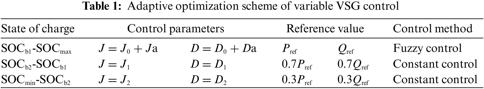
In order to reduce the negative impact on the power grid when the energy storage power station is under power shortage and actively cuts off the network, it is necessary to imitate the normal shutdown working principle of the conventional generator set, adopt the buffer control strategy when the battery is at low SOC, actively reduce the power output of the energy storage system step by step, and select new inertia and damping parameters as shown in Table 1, to ensure that the frequency fluctuations are still within the normal range during the gradual decline of the output. Meanwhile, this control strategy provides sufficient response time for other power supply frequency modulation systems.
4.2 Parameters J and D Influence on Frequency Characteristics
According to the derivation of the expression of virtual synchronous machine output active power and reactive power in reference [25], it can be concluded that:
where Zf, θ, δ are respectively the output filter impedance, impedance angle and output voltage phase of VSG, which can be expressed as:
Calculate the voltage amplitude Es and voltage phase δs corresponding to the stable operating point:
where Pe and δ satisfy the following relationship:
According to Eq. (1), taking small signal model analysis method with reference to SG, and obtaining second-order transfer function between VSG’s active power output and input, as shown in Eq. (20). And by analyzing the above second order system, this paper’s VSG natural angular frequency and damping ratio are available in the following equations:
The initial inertia J0 of the VSG controller is designed according to the natural oscillation frequency of SG (0.628~15.700 rad/s). After determining the oscillation angular frequency of VSG, consider the concept of optimal second-order system and make ζ = 0.707 to obtain faster response speed and lower overshoot. And so D0 can be obtained from Eq. (21).
When the VSG’s SOC is at SOCb1-SOCmax, under damping control (0 < ζ < 1) is adopted to ensure the energy storage system’s dynamic and steady-state characteristics; When its SOC is at SOCmin-SOCb1, to realize a smooth transition of output power, over damping control (ζ > 1) is adopted.
The VSG’s frequency response characteristics are analyzed as shown in Fig. 6. The findings from the above studies suggest that when D is constant, the system’s natural oscillation angular frequency ωn and its damping ratio ζ gradually decreases with the increase of J. When J is constant and D grows, the ωn remains unchanged, while ζ increases gradually. And as shown in Fig. 6a, VSG’s overshoot and rise time decrease when J increases, meanwhile its adjustment time increases. Therefore, the increase of J will make VSG’s oscillation becomes more intense and slow down the system’s response speed. What is shown in Fig. 6b, VSG’s overshoot, rise time and adjustment time decrease, but the peak time will move forward. So as D increases, the VSG frequency response curve is more stable. After summarizing and analyzing the various behaviors of frequency under different VSG parameters, the following fuzzy controller can be designed.
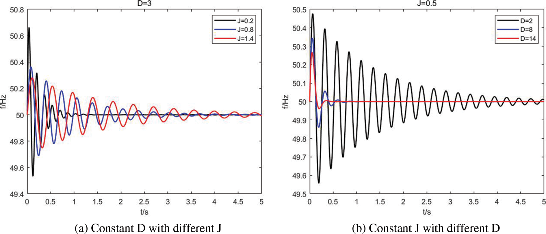
Figure 6: Influence of J and D with frequency modulation performance
To achieve adaptive adjustment of virtual inertia and damping coefficient, this paper adopts a fuzzy controller.
Fuzzy adaptive control brings the system better robustness and adaptability. The nonlinear advantage of fuzzy control is that it does not need to build a complex mathematical model in the VSG control, and it has flexible adaptability. As Fig. 7 shows, this fuzzy controller consists of fuzzification, fuzzy reasoning and defuzzification. Set VSG’s frequency deviation
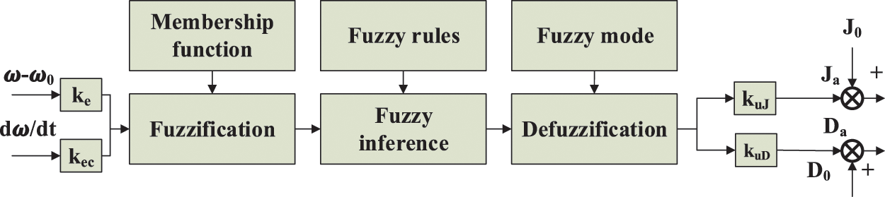
Figure 7: Fuzzy controller structure diagram
The fuzzy sets that define the above four are {negative big, negative small, zero, positive small, positive big}, noted as {NB, NS, Z, PS, PB}. Set appropriate membership functions to limit the value range of J and D to avoid system power and change rate exceeding the limit, which is shown in Fig. 8.
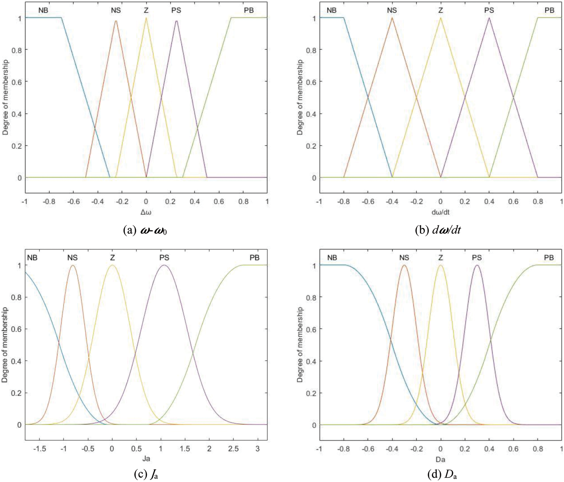
Figure 8: Membership functions of inputs and outputs
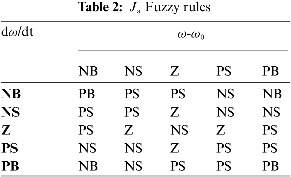
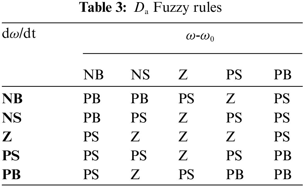
The fuzzy controller uses Mamdani fuzzy inference algorithm, the “minimum-maximum” synthesis rule, and the centroid defuzzification method. Specific fuzzy control rules adopted in this paper are shown in Tables 2 and 3.
5 Simulation Comparison and Analysis
To test the correctness and effectiveness of the theory and strategy mentioned above, three VSG control methods, Common VSG control (C-VSG), Conventional adaptive VSG control (S-VSG) and Improved VSG (I-VSG) control, are compared with each other. Note that the J and D of the C-VSG are constant. In addition, C-VSG does not consider the physical constraints on the energy storage side, and only power off and shutdown at SOCmin. The grid-connected simulation model of the energy storage power station as proposed in Fig. 1 has been constructed on the MATLAB platform.
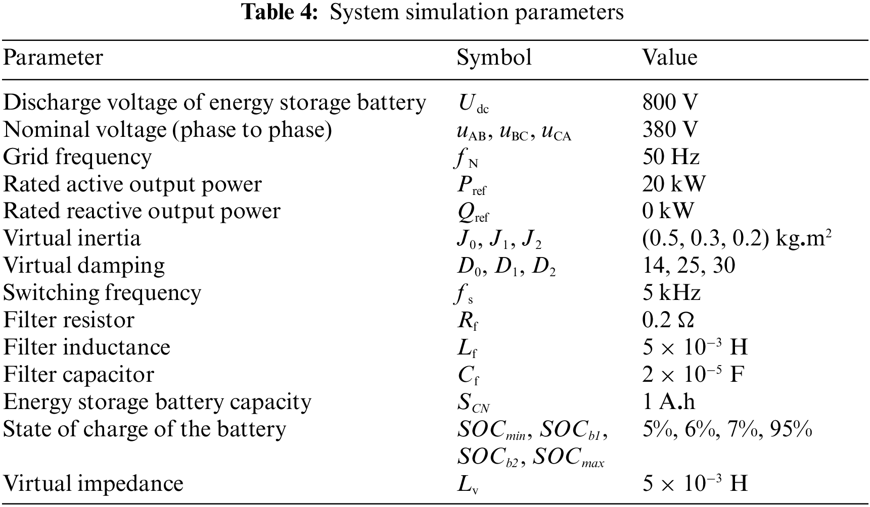
The energy storage converter takes a VSG control method just the same way as Fig. 2, and Table 4 shows the specific simulation parameters of VSG.
First, this paper verifies the influence of the discharge characteristics of the energy storage battery on the value range of J and D, as shown in Fig. 9.
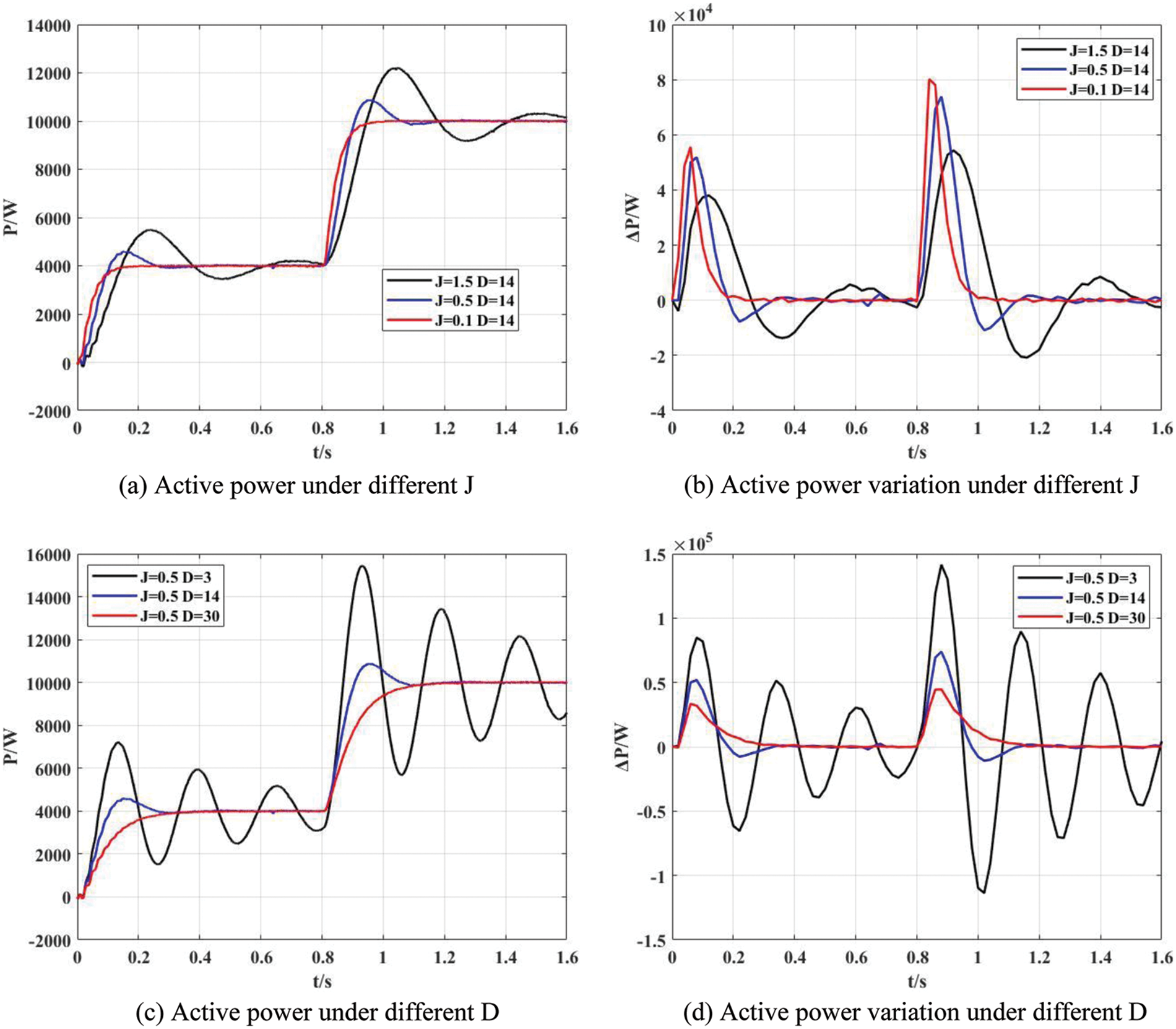
Figure 9: Simulations in case of different J and D
Set the system with a 5 kW, 1 kvar load. In this simulation experiment, the maximum discharge power limit of the energy storage battery is 12 kW. and the change threshold of discharge power is 80 kW/s. In the beginning, VSG operates with Pref = 4 kW and Qref = 1 kvar. After 0.8 s, the active power command value of the system increases to 10 kW.
As shown in Fig. 9, when the system power command changes, the system shows different response characteristics under different control parameters. The peak value of the active power change and its area surrounding the time axis is the required energy storage margin at this time.
In Figs. 9a, 9c, when J = 1.5, D = 14 and J = 0.5, D = 3, the power fluctuation is large, the overshoot time is long, the maximum value exceeds the power limit, so the system response exceeds the capacity range of the energy storage unit.
As shown in Fig. 9b, when J = 0.1 and D = 14, the maximum power change rate is80.164 kW/s, which is greater than the physical limit of the power change rate, exceeding its performance accessibility, so it cannot be achieved.
If J = 0.5 and D = 14, as shown in Figs. 9a, 9b, when the active power command changes, its power change rate is up to 73.85 kW/s and is far from the limit value of the power change rate, so the system operates normally and safely. At this time, VSG is under damping control.
If J = 0.5 and D = 30, it can be seen that when VSG implements over-damping control, both power and power change rate meet operation constraints, and only the adjustment time is slightly extended. Therefore, the over-damping control can be adopted when the SOC is low. Since large system interference will not occur in a short time, the over-damping control with fixed parameters can maximize and weaken the adverse impact on the power grid when the output power drops.
Then, this paper verifies the function of the VSG fuzzy adaptive control module, as shown in Fig. 10. In this comparative experiment, it is assumed that SOC is in the normal working zone, and compares three different VSG control modes.
1. Constant parameter VSG, C-VSG: J = 0.5, D = 14;
2. Conventional adaptive VSG, S-VSG: J0 = 0.5, D0 = 14;
3. Improved adaptive VSG (Table 1), I-VSG: J0 = 0.5, D0=14.
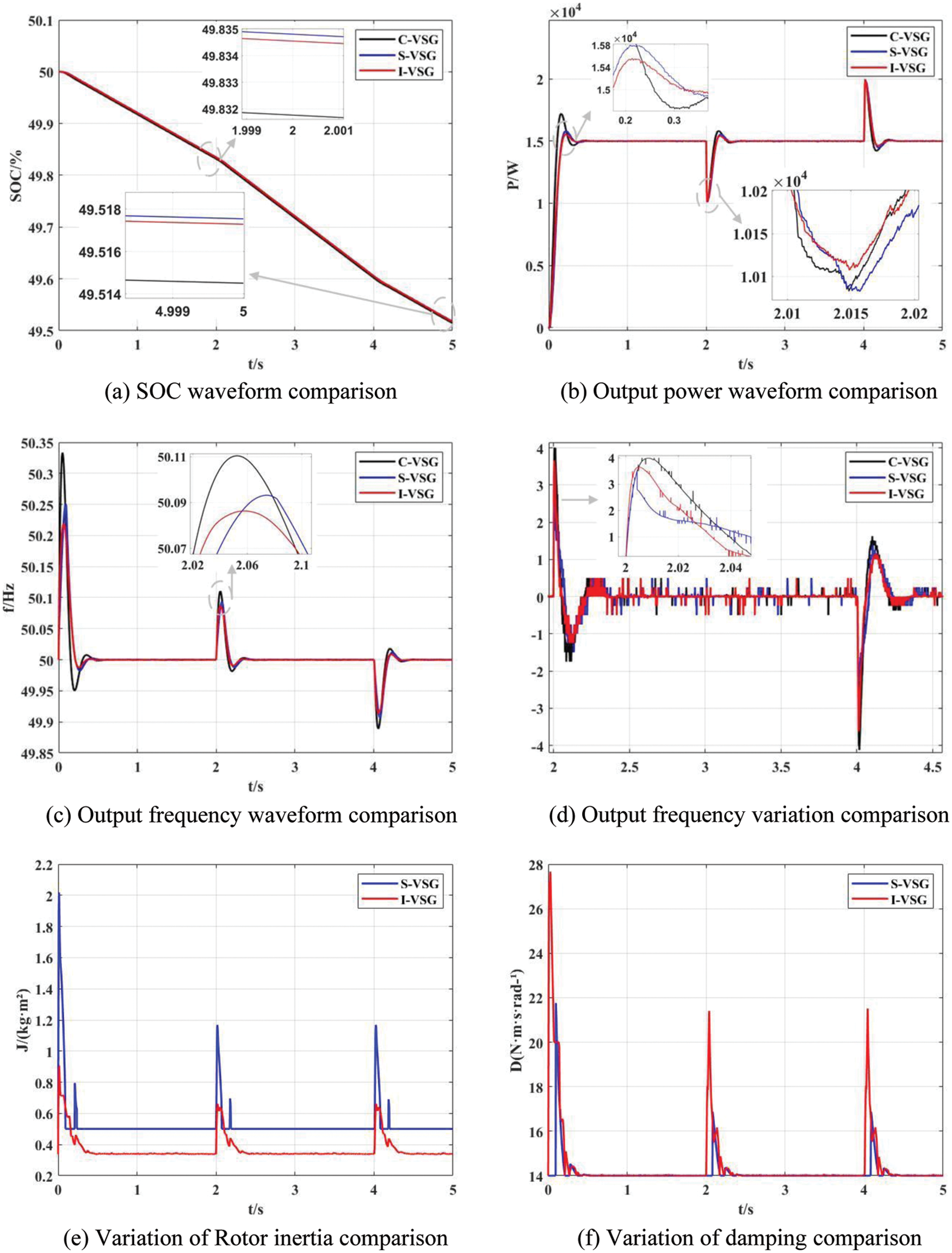
Figure 10: Load disturbance output comparison
The conventional adaptive control strategy as the control group is shown in Eqs. (22) and (23):
wherein, J0 and D0 are respectively the moments of inertia and damping coefficient of the VSG during stable operation; a and b are the adjustment coefficients of the moment of inertia and damping coefficient, respectively; KJ and KD are change thresholds. The collaborative adaptive control flow chart is shown in Fig. 11, where KJ = 2.5, KD = 0.1, a = 0.05, and b = 5.
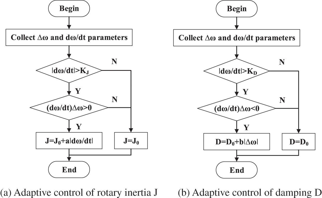
Figure 11: Flow chart of adaptive control for J and D
Fig. 10 shows the output comparison of the VSG under different control strategies. The initial SOC of VSG under each control strategy is 50%. The simulation duration is 5 s, the load active power is 5 kW, and the reactive power is 1 kvar. The load is increased by 5 kW in 2 s, and the set value is restored in 4 s.
It can be seen from Fig. 10a that VSG under parameter adaptive control consumes significantly less power. Fig. 10b shows the response curves of the VSG output active power under different control strategies. When the load power suddenly increases by 5 kw at 2 s, the active power of C-VSG, S-VSG and I-VSG drops to 100,830 kW, 100,826 W and 101,077 W, respectively, and recovers to the rated output in 2.41, 2.43 and 2.39 s, respectively.
Fig. 10c shows that the adaptive change has a significant impact on the frequency change rate. When the frequency is subject to the initial load disturbance, the buffer effect of C-VSG control on the disturbance is general, and the maximum overshoot is 0.33 Hz; S-VSG control can better buffer frequency fluctuation, and the maximum overshoot is 0.25 Hz; The fuzzy adaptive VSG control has the best buffering effect on frequency fluctuation, and the maximum overshoot is 0.22 Hz.
When the load power suddenly increases, the frequency deviation of C-VSG exceeds 0.1 Hz, and the oscillation duration is about 0.6 s. As for S-VSG, its maximum frequency deviation is reduced to 0.093 Hz, and the adjustment time is reduced to 0.51 s. When I-VSG is used, the maximum frequency deviation is reduced to 0.086 Hz, and the adjustment time is reduced to 0.42 s. When the frequency deviation exceeds 0.1 Hz, the adaptive increase of D can significantly restrain the frequency deviation. Moreover, when the disturbance is eliminated, the fuzzy adaptive VSG control strategy can restore the frequency to stability as quickly as possible.
The range of RoCoF is also specified in Fig.10d to ensure the system stability; the absolute maximum RoCoF with C-VSG method is 4.27 Hz/s. Using S-VSG and I-VSG control method, the maximum RoCoF becomes 3.50 and 4.00 Hz/s, respectively. Note that, using adaptive control, the maximum RoCoF has decreased by 6%~18%, which improves the system frequency stability.
Figs. 10e, 10f show the changes of J and D under S-VSG control and I-VSG control. In Fig. 10e, there are sharp spikes of the J waveform of S-VSG, which is caused by the uneven frequency change of the virtual rotor, sudden changes of dω/dt at the frequency inflection point.
Finally, this paper verifies the hierarchical power reduction control strategy when the SOC of the battery is in the buffer zone, as shown in Fig. 12.
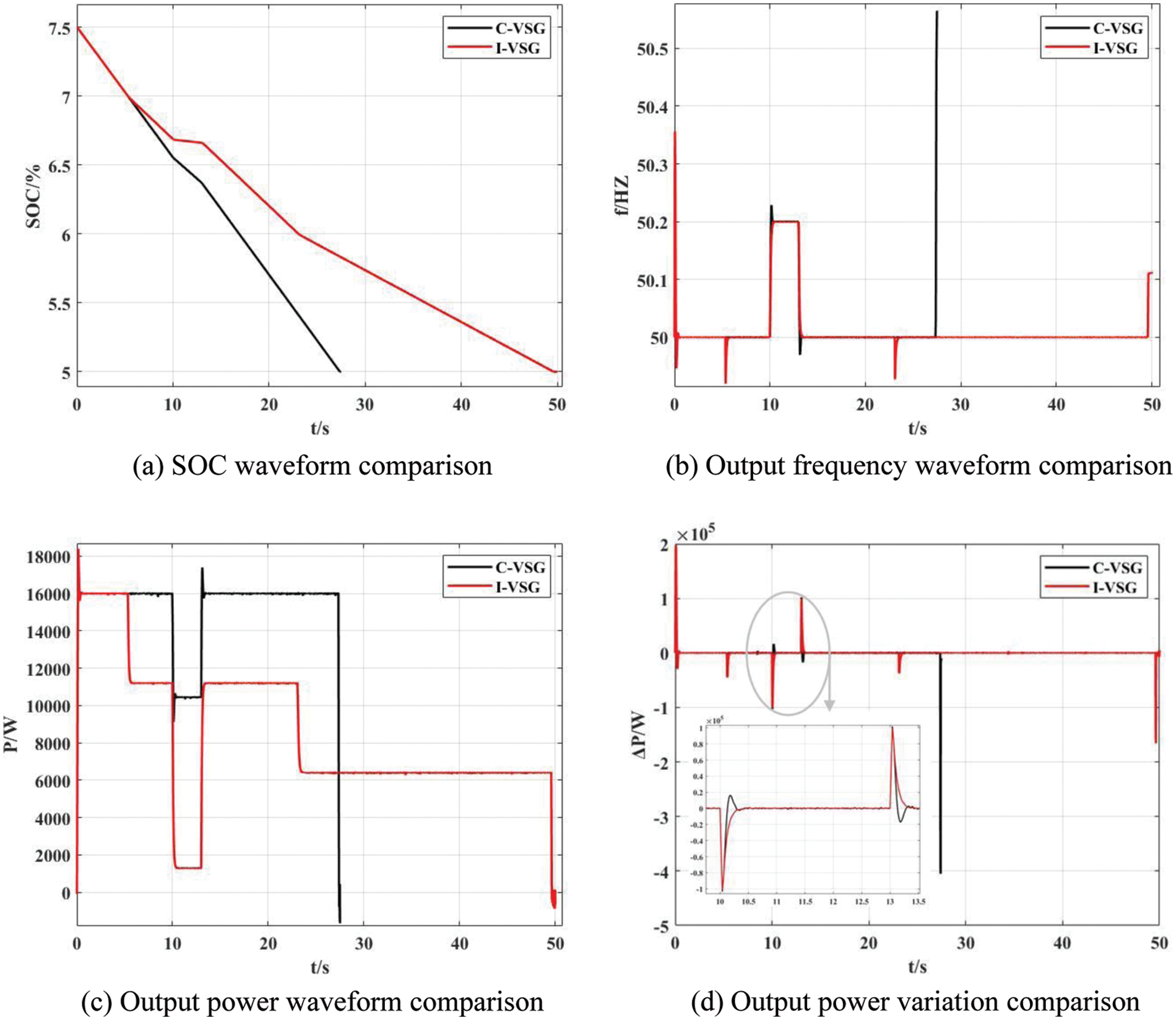
Figure 12: Comparisons for power and frequency with low SOC
The system is initially loaded with a 3 kW load. In the beginning, VSG operates withPref = 16 kW and Qref = 0 var. At 10 s, the system frequency suddenly increases by 0.2 Hz, and the frequency is recovered at 13 s.
To obtain a more obvious battery SOC curve, small capacity batteries are selected as the power supply in this test, and the graded power reduction operation strategy is started when the SOC reaches 7% and 6%, respectively.
By observing Fig. 12a, it can be found that the SOC of C-VSG control reaches the minimum value at 27.37 s, then the battery system is in a limited discharge state and stops discharging and actively disconnects from the converter, and from Fig. 12c we can see its output power drops sharply to a negative value, which means at that time, the energy storage converter did not supply power to the power grid, but consumed power from the power grid. The connection between the converter and the power grid should be immediately disconnected to reduce power loss. In practice, when the converter is going to stop power transmission, it should first disconnect the connection with the power grid side, then disconnect the DC input switch, and finally, the energy storage device can disconnect the interaction with the outside system.
More so, as shown in Fig. 12b, from 27.37 s C-VSG’s frequency management loses energy support, and the grid frequency is no longer maintained near the rated value.
Also, it can be seen from Fig. 12c that the I-VSG control starts active power reduction operation at 5.326 s and reduces its output power again at 23.075 s. At 49.594 s, the SOC reaches the lowest value that can VSG be operated, and the battery is disconnected from the converter. Due to different control strategies, I-VSG markedly prolongs the discharge working time. Thus, the power shortage in unit time is reduced, and the impact of VSG shutdown on the power grid is reduced.
Due to the use of overdamping control, the system output power under the I-VSG control strategy does not overshoot, and its power change rate is smaller, as shown in Fig. 12d. So the requirement for battery energy storage margin is smaller. The improved VSG control strategy effectively smoothes the short-term power fluctuation caused by the disconnection of the ionization network of the battery and retains sufficient frequency modulation capability during a sudden change in system frequency.
In the actual design of an energy storage power station, the capacity of the energy storage battery pack is far greater than 1Ah, and normally the installed capacity varies from 1 to 100 MW. Therefore, it is not only necessary to reasonably design the value of SOCb1 and SOCb2, so that the operation time of each level of power reduction is about 30 s, but also to add multiple buffer zones when necessary, so as to limit the change rate of the active power of the energy storage plant to a reasonable range.
This article is based on fuzzy control theory, energy storage converter model and fuzzy adaptive control strategy of VSG, this paper studies the rationality of VSG control parameter selection when the energy storage unit is in a safe working state, and analyzes the relationship between two parameters, inertia and damping, and dynamic performance of the energy storage converter, so as to realize the adaptive VSG control strategy of the energy storage converter. The following conclusions are obtained through simulation analysis of a grid-connected model of an energy storage power station:
1. Considering the physical constraints of energy storage, the output power and its power change rate of VSG are always within the allowable range of battery performance. This control strategy sacrifices the dynamic regulation performance of the energy storage converter, thus ensuring the overall dynamic response capability of the whole energy storage system. Therefore, the energy storage battery will not have over-discharge and other adverse phenomena, which protects the safety and service life of the battery. In the actual construction of energy storage power stations, batteries with large capacity, high discharge rate and large threshold of power change rate should be selected as the power supply to cut down the negative impact on the output performance of the energy storage system.
2. When the load changes suddenly, fuzzy adaptive VSG control can better improve response characteristics of power grid frequency and output power, ultimately enhancing the robustness of energy storage systems.
3. The power grading and over damping operation described in this paper can also be applied to the shutdown preparation of the energy storage converter, and future research work will focus on the adaptive P-ω Control coefficient and Q-E control coefficient based on SOC.
Funding Statement: This project is supported by the Science and Technology Project of State Grid Corporation of China (W22KJ2722005); Tianyou Innovation Team of Lanzhou Jiaotong University (TY202009).
Conflicts of Interest: The authors declare that they have no conflicts of interest to report regarding the present study.
References
1. Liu, Z. C., Peng, D. G., Zhao, H. R., Wang, D. H., Liu, Y. C. (2021). Development prospects of energy storage participating in power system auxiliary services under dual carbon goals. Energy Storage Science and Technology, 1–12. https://doi.org/10.19799/j.cnki.2095-42392021.0431 [Google Scholar] [CrossRef]
2. Gao, N., Zhang, H. Y., Wang, Z. Q. (2020). Planning for site selection and capacity determination of distributed energy storage in regional power grid. High Voltage Apparatus, 56(8), 52–58. [Google Scholar]
3. Xi, X. X., Xiong, M. P., Yuan, J. H. (2020). Economy analysis of energy storage system in wind farm generation side. Smart Power, 48(11), 16–21+47. [Google Scholar]
4. He, K. X., Ma, S. L., Ma, Z., Aoyu, X. U. E. (2021). Energy storage technology development trend and policy environment analysis. Distributed Energy, 6(6), 45–52. [Google Scholar]
5. Larcher, D., Tarascon, J. M. (2015). Towards greener and more sustainable batteries for electrical energy storage. Nature Chemistry, 7(1), 19–29. https://doi.org/10.1038/nchem.2085 [Google Scholar] [PubMed] [CrossRef]
6. Tang, B., Shan, L., Liang, S., Zhou, J. (2019). Issues and opportunities facing aqueous zinc-ion batteries. Energy & Environmental Science, 12(11), 3288–3304. https://doi.org/10.1039/C9EE02526J [Google Scholar] [CrossRef]
7. Blanc, L. E., Kundu, D., Nazar, L. F. (2020). Scientific challenges for the implementation of Zn-ion batteries. Joule, 4(4), 771–799. https://doi.org/10.1016/j.joule.2020.03.002 [Google Scholar] [CrossRef]
8. Li, J. L., Yuan, X. D., Yu, Z. G., Ge, L. (2019). Comments on power quality enhancement research for power grid by energy storage system. Automation of Electric Power Systems, 43(8), 15–24. [Google Scholar]
9. Luo, N., Li, J. L. (2012). Research progress of energy storage technology in power system. Power System and Clean Energy, 28(2), 71–79. [Google Scholar]
10. Zhong, Q. C. (2017). Power-electronics-enabled autonomous power systems: Architecture and technical routes. IEEE Transactions on Industrial Electronics, 64(7), 5907–5918. https://doi.org/10.1109/TIE.2017.2677339 [Google Scholar] [CrossRef]
11. Delille, G., Francois, B., Malarange, G. (2012). Dynamic frequency control support by energy storage to reduce the impact of wind and solar generation on isolated power system’s inertia. IEEE Transactions on Sustainable Energy, 3(4), 931–939. https://doi.org/10.1109/TSTE.2012.2205025 [Google Scholar] [CrossRef]
12. Zhong, Q. C., Weiss, G. (2011). Synchronverters: Inverters that mimic synchronous generators. IEEE Transactions on Industrial Electronics, 58(4), 1259–1267. https://doi.org/10.1109/TIE.2010.2048839 [Google Scholar] [CrossRef]
13. Zhong, Q. C. (2017). Virtual synchronous machines and autonomous power systems. Proceedings of the CSEE, 37(2), 336–349. https://doi.org/10.13334/j.0258-8013.pcsee.162325 [Google Scholar] [CrossRef]
14. Torres, M. A. L., Lopes, L. A. C., Moran, L. A. T., Espinoza, J. R. C. (2014). Self-tuning virtual synchronous machine: A control strategy for energy storage systems to support dynamic frequency control. IEEE Transactions on Energy Conversion, 29(4), 833–840. https://doi.org/10.1109/TEC.2014.2362577 [Google Scholar] [CrossRef]
15. Markovic, U., Chu, Z. D., Aristidou, P., Hug, G. (2019). LQR-based adaptivevirtual synchronous machine for power systems with high inverter penetration. IEEE Transactions on Sustainable Energy, 10(3), 1501–1512. https://doi.org/10.1109/TSTE.2018.2887147 [Google Scholar] [CrossRef]
16. Shi, R. L., Zhang, X., Hu, C., Xu, H. Z., Gu, J. et al. (2018). Self-tuning virtual synchronous generator control for improving frequency stability in autonomous photovoltaic-diesel microgrids. Journal of Modern Power Systems and Clean Energy, 6(3), 482–494. https://doi.org/10.1007/s40565-017-0347-3 [Google Scholar] [CrossRef]
17. Li, J., Zhou, S., Xu, S. (2008). Fuzzy control system design via fuzzy lyapunov functions. IEEE Transactions on Systems, Man, and Cybernetics, Part B (Cybernetics), 38(6), 1657–1661. https://doi.org/10.1109/TSMCB.2008.928224 [Google Scholar] [PubMed] [CrossRef]
18. Feng, G. (2006). A survey on analysis and design of model-based fuzzy control systems. IEEE Transactions on Fuzzy Systems, 14(5), 676–697. https://doi.org/10.1109/TFUZZ.2006.883415 [Google Scholar] [CrossRef]
19. Andalib-Bin-Karim, C., Liang, X., Zhang, H. (2018). Fuzzy-secondary-controller-based virtual synchronous generator control scheme for interfacing inverters of renewable distributed generation in microgrids. IEEE Transactions on Industry Applications, 54(2), 1047–1061. https://doi.org/10.1109/TIA.2017.2773432 [Google Scholar] [CrossRef]
20. Pradhan, C. C., Bhende, N., Samanta, A. K. (2018). Adaptive virtual inertia-based frequency regulation in wind power systems. Renewable Energy, 115(5), 558–574. https://doi.org/10.1016/j.renene.2017.08.065 [Google Scholar] [CrossRef]
21. Karimi, A., Khayat, Y., Naderi, M., Dragičević, T., Mirzaei, R. et al. (2020). Inertia response improvement in AC microgrids: A fuzzy-based virtual synchronous generator control. IEEE Transactions on Power Electronics, 35(4), 4321–4331. https://doi.org/10.1109/TPEL.2019.2937397 [Google Scholar] [CrossRef]
22. Kerdphol, T., Watanabe, M., Hongesombut, K., Mitani, Y. (2019). Self-adaptive virtual inertia control-based fuzzy logic to improve frequency stability of microgrid with high renewable penetration. IEEE Access, 7, 76071–76083. https://doi.org/10.1109/ACCESS.2019.2920886 [Google Scholar] [CrossRef]
23. Ebrahimi, M., Khajehoddin, S. A., Karimi-Ghartemani, M. (2019). An improved damping method for virtual synchronous machines. IEEE Transactions on Sustainable Energy, 10(3), 1491–1500. https://doi.org/10.1109/TSTE.2019.2902033 [Google Scholar] [CrossRef]
24. Hu, A. P., Yang, B., Pan, P. P., Li, G. J., Tao, Y. B. et al. (2018). Study on inertial characteristics of energy storage system with power electronic interface. Proceedings of the CSEE, 38(17), 4999–5008+5297. https://doi.org/10.13334/j.0258-8013.pcsee.172143 [Google Scholar] [CrossRef]
25. Yuan, C., Liu, C., Zhao, T. Y., Chen, M., Xiao, X. N. (2017). Research on operating boundary of virtual synchronous machine based on physical constraint of energy storage system. Proceedings of the CSEE, 37(2), 506–516. https://doi.org/10.13334/j.0258-8013.pcsee.161121 [Google Scholar] [CrossRef]
26. Chen, M., Zhou, D., Blaabjerg, F. (2021). A decentralized adaptive soc balancing strategy in VSG-based islanded power system. IECON 2021–47th Annual Conference of the IEEE Industrial Electronics Society, vol. 2021, pp. 1–6. Toronto, ON, Canada. https://doi.org/10.1109/IECON48115.2021.9589320 [Google Scholar] [CrossRef]
Cite This Article
 Copyright © 2023 The Author(s). Published by Tech Science Press.
This work is licensed under a Creative Commons Attribution 4.0 International License , which permits unrestricted use, distribution, and reproduction in any medium, provided the original work is properly cited.
 Downloads
 Citation Tools