
 Submit a Paper
 Propose a Special lssue
 Open Access
ARTICLE

Parameter Design of Current Double Closed Loop for T-Type Three-Level Grid-Connected Inverter
1 Electric Power Research Institute, State Grid Jiangsu Electric Power Co., Ltd., Nanjing, 211103, China
2 Zhenjiang Sanxin Power Supply Company, State Grid Jiangsu Electric Power Co., Ltd., Zhenjiang, 212001, China
* Corresponding Author: Tiankui Sun. Email:
Energy Engineering 2023, 120(7), 1621-1636. https://doi.org/10.32604/ee.2023.026948
Received 05 October 2022; Accepted 26 December 2022; Issue published 04 May 2023
 View Full Text
 Download PDF
Abstract
To reduce current harmonics caused by switching frequency, T-type grid-connected inverter topology with LCL filter is adopted. In view of the disadvantages of the slow response speed of the traditional current control and the failure to eliminate the influence of the LCL filter on the grid-connected current by using current PI control alone, a current double closed loop PI current tracking control is proposed. Through the theoretical analysis of the grid-connected inverter control principle, the grid-connected inverter control model is designed, and the transfer function model of each control link is deduced, and the current loop PI regulator is designed at last. The simulation results show that the control strategy is feasible.Keywords
At present, distributed generation technology has become a hot research topic in the electric power industry due to its advantages such as diverse power generation methods and less construction cost. New energy integrating into the power system is a key problem to be solved. The grid-connected type inverter is a new energy power generation device and an interface of energy conversion between power systems, its basic function is to convert direct current produced by renewable clean energy into alternating current that can be incorporated into the power grid, and it plays a vital role in the stable operation of the power system [1]. Professor Nabae from Nagaoka University of science and technology in Japan proposed a Neutral Point Clamped (NPC) inverter topology in 1980. The topology structure changes the topology of the main circuit by adding clamp diodes. When the switch is turned off, the voltage borne by the switch is half of the bus side, thus reducing the withstand voltage level of the switch, realizing the use of low-voltage switching devices in high-power applications [2]. Compared with the traditional two-level structure, the output waveform of T-type three-level structure is more similar to sine wave, and the harmonic component of current and voltage is low; Compared with the diode clamped three-level structure, the number of power devices used is reduced, the voltage level of devices is reduced, and the switching loss is small [3–5]. Therefore, adopting T-type three-level grid connected inverter can greatly improve the grid connected power quality and improve the grid connected effect.
At present, the widely used filters are L-type, LC type and LCL type. L-type filter is a first-order filter, and the inductance must be increased to obtain a good filtering effect. LC filter has better effect than L filter in filtering high-frequency harmonics, which is usually used in the case of off-grid; LCL filter is a third-order filter. It has high impedance to high-frequency components. Besides, high frequency harmonic current can play a large attenuation effect.
The control modes of inverters can be divided into two categories: voltage type control and current type control [6,7]. The grid connected current of voltage control mode is open-loop control, resulting in poor dynamic performance of the system. In practice, this method is barely applied. Grid connected current control methods mainly include hysteresis control, repetitive control, deadbeat control, proportional integral controller (PI controller), etc. [8,9]. The switching frequency of the switch controlled by the feedback hysteresis loop is not constant, and the harmonic frequency also changes over time, which increases the difficulty of the design of the output filter. Repetitive control can effectively suppress repetitive interference in the output voltage of the inverter, but it cannot work in sudden external interference. The deadbeat control has high control requirements. It requires that the duty ratio must be calculated by the current beat and output by the current beat. Otherwise, the characteristics of the system will be affected and even the stability of the system will be destroyed. Reference [10] adopts the hysteresis based model predictive control strategy, which combines the filter based capacitor voltage feedback with the output current reference value prediction to suppress resonance. Reference [11] adopts double closed-loop control, with the inner loop as the dynamic response link of the system and the outer loop as the repeated compensation link of harmonics. Reference [12] uses active damping with capacitive current feedback in the inner loop, and quasi-PR control with the grid connected current in the outer loop. PR regulator can make the fundamental wave or specific harmonic loop gain large, which can eliminate the steady state error of the grid-connected current. PI control has the ability to suppress the harmonics below the cutoff frequency of the system, the principle is simple, easy to implement, and strong robustness.
When the inverter side current is used for closed-loop control, the phase difference between the grid connected current and the grid voltage will be caused due to the filter capacitor, and the power factor will be reduced [13], and the LCL resonance peak cannot be well suppressed. Therefore, this paper uses the grid connected current as the outer loop control variable to realize the grid connection of unit power factor, and the capacitor current as the inner loop control variable to increase the system damping. The transfer function of the current double closed loop is derived and the control parameters of the double closed loop are designed by using the open loop root locus and the open loop bode diagram. This control strategy can not only suppress the oscillation of the system, but also improve the amplitude margin and phase margin of the system and enhance the stability of the system.
The main work of this paper is as follows: (1) Configure the parameters of the inner loop and the outer loop respectively to make the controller not only have appropriate damping, but also have good dynamic response performance. (2) Specific design formulas of inner loop and outer loop parameters are given. (3) Draw the open-loop baud diagram before and after the control, and verify the rationality of the parameter design. (4) Verify the steady-state and dynamic response performance of the system under this parameter design.
2 Topological Structure of Three-Phase T-Type Grid-Connected Inverter
The grid-connected structure of T-type three-level inverter is shown in Fig. 1. Compared with NPC type, T-type reduces two diodes, switching loss and volume of the inverter. Therefore, this topology not only has the characteristics of low loss and high reliability of two-level topology, but also has the advantages of low harmonic output and high efficiency of three-level inverter. Therefore, this paper chooses T-type inverter as the research object.
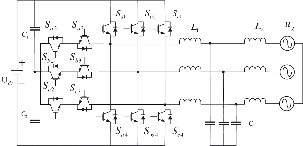
Figure 1: T-type three-level inverter connected to the grid
3.1 Analysis of Grid-Connected Inverter Control System
Capacitor circuit and grid-connected current double closed-loop control are selected. The dynamic structure of this control mode is shown in Fig. 2.
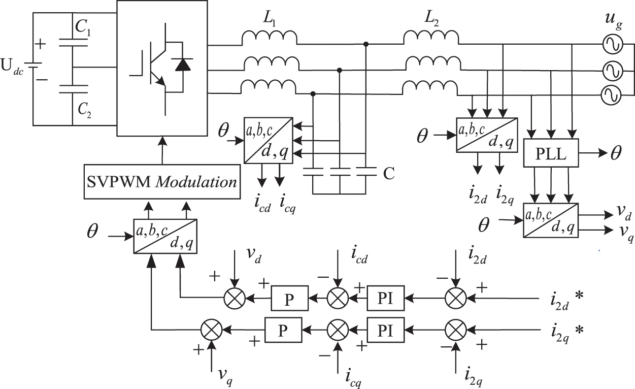
Figure 2: Current double closed loop control structure diagram
The whole inverter system should realize the control of DC bus voltage stabilization, phase locking and grid-connected current. The current loop is controlled by current double closed loop, the active damping based on capacitive current feedback is used to increase the system damping in the inner loop, and the unit factor current is used in the outer loop [14]. The phase information of grid voltage is obtained by phase locking to ensure that the grid-connected current and grid voltage are in the same frequency and phase. The current reference signal differs from the current sampling value, and the error signal passes through the current loop PI. The sum of current loop PI output and grid connected voltage is modulated by SVPWM to obtain the driving signal.
3.1.1 Current Inner Loop Control
LCL filter has third-order characteristics, the frequency response at the resonant frequency will show a low impedance to zero impedance, so that there will be a resonance peak at the resonance. If not restrained, it will produce a large number of harmonics, make the power grid oscillation, resulting in the instability of the system. Therefore, the resonant peak must be suppressed, that is, the damping of the system must be increased. There are two ways to increase damping, one is passive damping, the other is active damping [15–17]. Passive damping is through series or parallel resistance to increase the damping, the realization method is simple and not limited by the switching frequency, but at the same time will bring losses to the system, reduce the power factor of the system, so in high power occasions, passive damping is not applicable. The active resistive method is used to suppress the harmonic vibration peak by feeding back the voltage or current of the suitable filter wave electrical sensation or filter capacitor. No additional passive components are needed and there is no loss of the external energy.
The passive damping control effect of capacitor shunt resistance is the best, and its control block diagram is shown in Fig. 3.
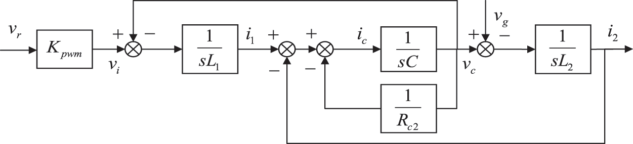
Figure 3: Passive damping control block diagram
Among them, the active resistance method based on the capacitive current proportional feedback can achieve the same resistance effect as the passive damping method of capacitor parallel resistance. If the capacitor current is taken as the feedback variable and the feedback function is changed, the feedback function can be obtained as
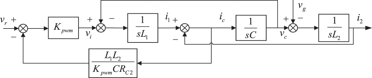
Figure 4: Active damping control block diagram based on capacitive current feedback
3.1.2 Current Outer Loop Control
The inner loop control of the capacitor circuit only increases the damping of the system, and does not consider the response in the frequency domain and time domain, so the stability of the system cannot be guaranteed. Therefore, it is necessary to control the grid-connected current of the system by proportional integration, and design PI parameters according to the root trajectory and frequency response of the system, so that the system can meet the stability requirements.
The diagram of current double closed loop control block after introducing passive damping control based on capacitor circuit feedback is shown in Fig. 5. Where k is the proportional coefficient of the inner loop proportional regulator.
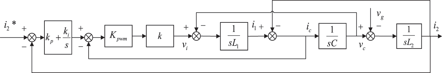
Figure 5: Diagram of current double closed loop control block
Derived from the structural block diagram, its open-loop transfer function is Eq. (1).
Draw the root locus the system, as shown in Fig. 6.
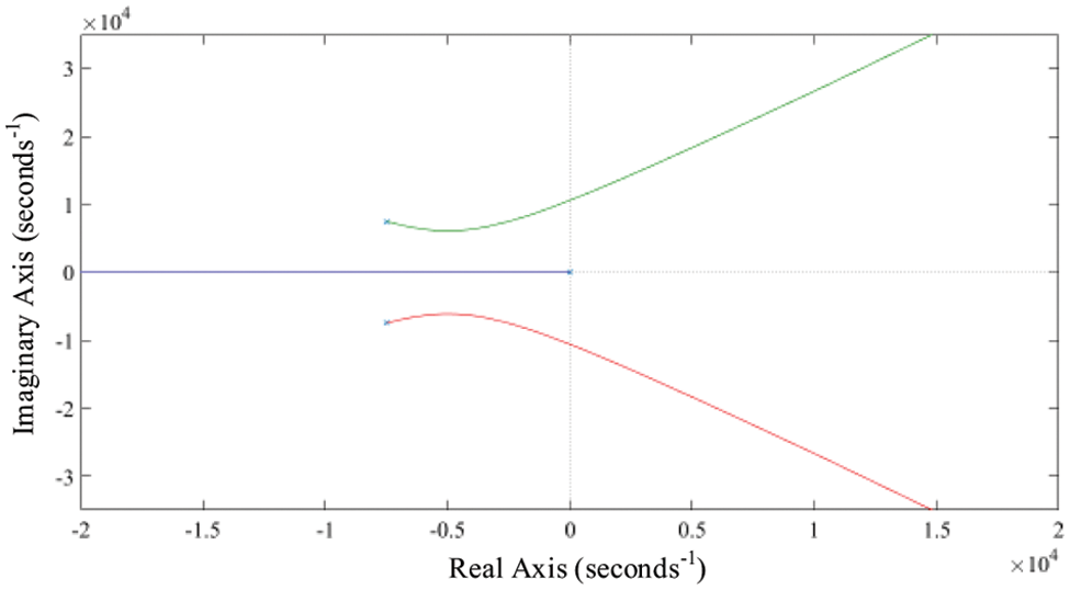
Figure 6: System root locus
It can be seen from the root locus that when
Lists its Rous Table:
In Rous criterion, if the coefficients in the first row are all positive, then the system is stable, and the following relations must be met:
3.2 Parameter Design of PI Controller
3.2.1 Parameter Design of Capacitive Current Inner Loop
Without considering the outer loop, analyze the inner loop control based on capacitive current feedback, increase the damping of the system by the inner loop, and then propose its mathematical model, as shown in Fig. 7, where the output signal Gi(s) of the outer loop current regulator is shown.
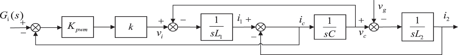
Figure 7: Inner loop control block diagram
The transfer function of the inner loop can be obtained as Eq. (7).
It is a second-order system, and its damping ratio can be obtained as Eq. (8).
According to the damping ratio formula, the larger k is, the larger the system damping is, and the better the inhibition effect of resonant peak is. However, excessive damping will worsen the response performance of the system and lengthen the adjustment time. Damping effect and dynamic performance of the system should be considered at the same time [18], so
The inner loop baud diagram is shown in Fig. 8.
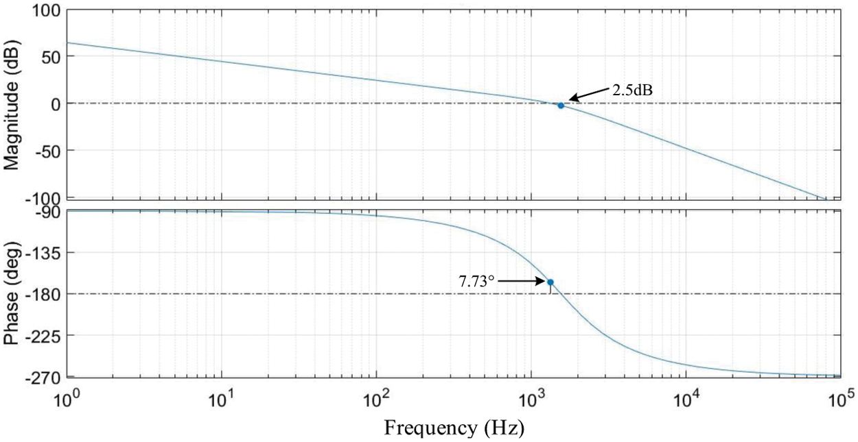
Figure 8: Inner loop bod diagram
After the addition of capacitive current feedback, the damping of the system increases and the resonance peak is effectively controlled, but the amplitude margin is only 2.5 dB and the phase angle margin is only 7.73°, which cannot meet the requirements of frequency domain indicators.
3.2.2 Parameter Design of Grid-Connected Current Outer Loop
The turning frequency of the outer loop PI controller can be represented by the first-order differential link, thus establishing the relationship between the turning frequency and PI controller parameters, as shown in the Eq. (9).
To meet the amplitude and frequency characteristics after correction, the turning frequency of PI controller is set at 160 Hz, then Eq. (10) is established.
According to the characteristics of LCL filter, when the frequency is lower than the resonant frequency, the capacitor branch does not work, and the filter can be regarded as a single inductor filter. When the frequency is higher than the turning frequency of PI controller, the integral coefficient Ki basically has no effect, and PI controller can be equivalent to P controller [19]. Thus, the open loop transfer function of the system can be simplified by Eq. (11).
Since the gain of the system at the cutoff frequency is 1, Eq. (12) is obtained.
After finishing, the expression of Kp can be obtained as Eq. (13).
If Kp is increased, the dynamic response speed of the system will be faster. However, increasing Kp will lead to the increase of cut-off frequency, which will make the system cut-off frequency close to the resonant frequency, and the stability margin of the system will also become lower. If the cutoff frequency is 800 Hz, Kp = 0.4608, Ki = 463.2068 can be obtained.
Double closed loop open loop bod diagram is shown in Fig. 9.
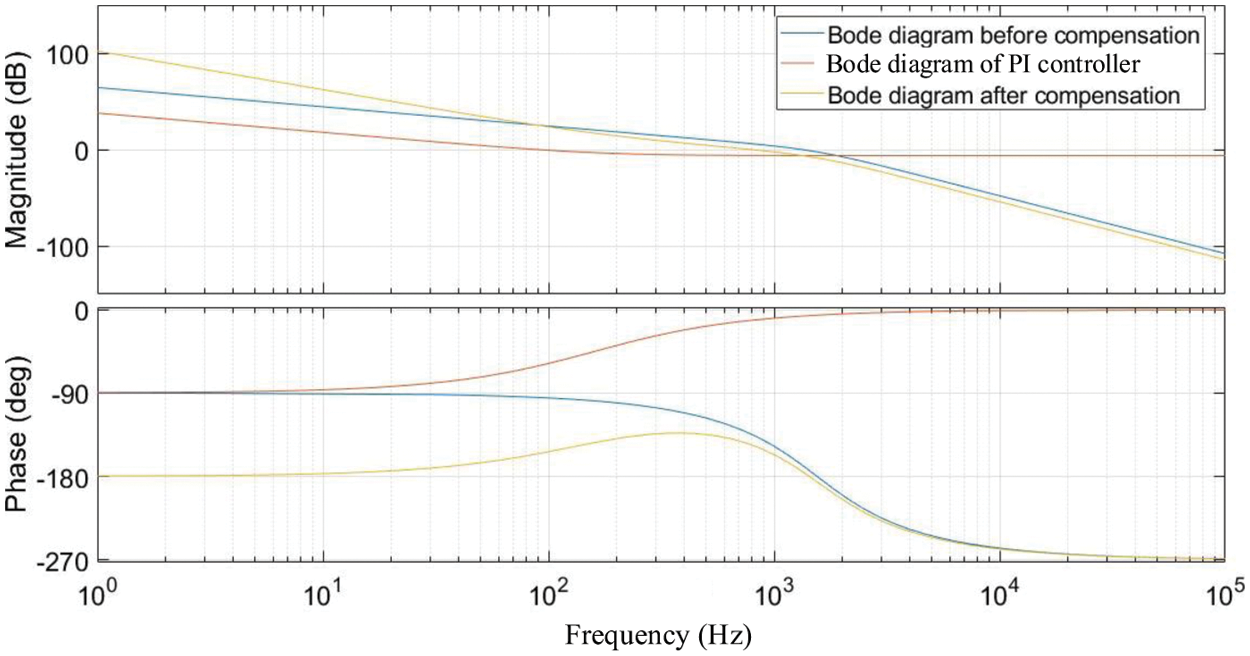
Figure 9: Double closed loop open loop bod diagram
The blue line represents the frequency response of the system before compensation, which is attenuated at a rate of –20 dB/dec in the low frequency band and –60 dB/dec in the high frequency band. The cutoff frequency is near resonance, and the amplitude margin and phase angle margin are both very low.
The red line represents the frequency response of the regulator, the turning frequency is 160 Hz, and the descending slope is –20 dB/dec.
The yellow line represents the frequency response of the system after correction, and the falling slope in the low frequency band is –40 dB/dec, which ensures good stability of the system. In the middle frequency band, the descending slope is –20 dB/dec and the middle frequency duration width is 5. The descending slope in the high frequency band is –60 dB/dec, and it has good harmonic suppression ability. At the same time, the cut-off frequency is advanced, which makes the system frequency response have good phase margin and amplitude margin.
It can be seen from the bode diagram that the amplitude margin after compensation is 7.4 dB and the phase angle margin is 34.4°, which meets the frequency domain performance of the inverter system.
For the study of grid-connected control technology at the output end of inverter, voltage outer loop is not designed since there’s no requirement for stablizing the DC bus voltage.
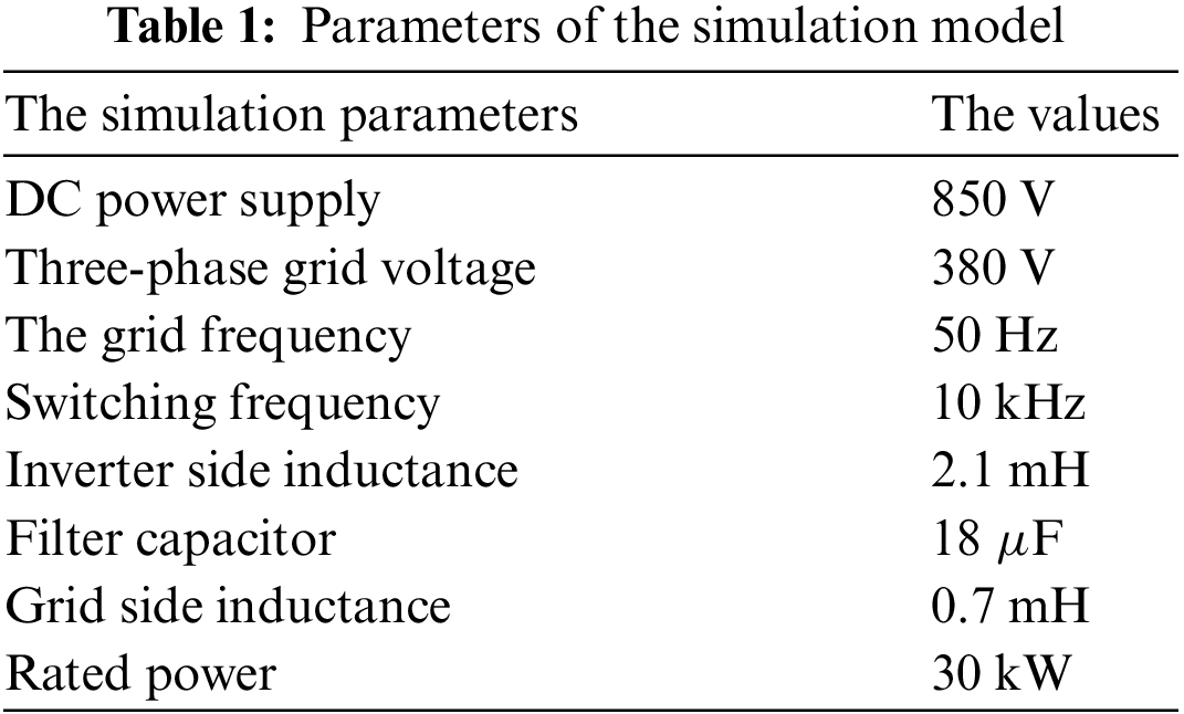
Set the amplitude of current reference signal, which can meet the rated demand when setting I2q* to 64.46 A. The simulation parameters are shown in Table 1.
When the inner loop is not added to control, the resonant peak of LCL filter can not be controlled, and the system loses stability. Phase A voltage and current are shown in Fig. 10.
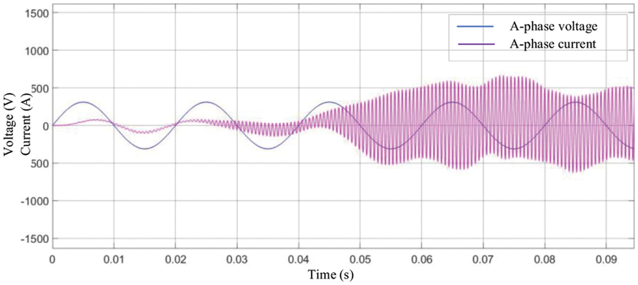
Figure 10: Control without inner loop
If the outer loop parameters are Kp = 0.7285, Ki = 1098.6. Phase A voltage and current are shown in Fig. 11.
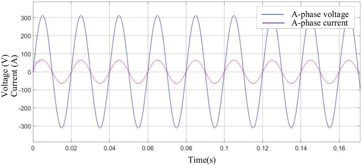
Figure 11: Phase A voltage and current
It can be seen that the system is stable after adding the inner loop, and its phase A harmonic analysis is shown in the Fig. 12.
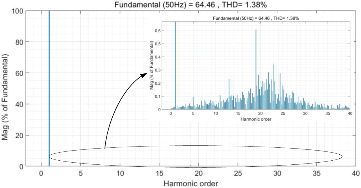
Figure 12: Phase A current harmonic analysis
The inverter is put into half-load from the zero state, and is put into full-load operation at 0.25 s, the grid-connected current waveform is shown in Fig. 13, and the active and reactive power is shown in Fig. 14. The system is in a stable state at the beginning, and loses stability after being put into full-load operation, and the dynamic response of the system does not meet the requirements.
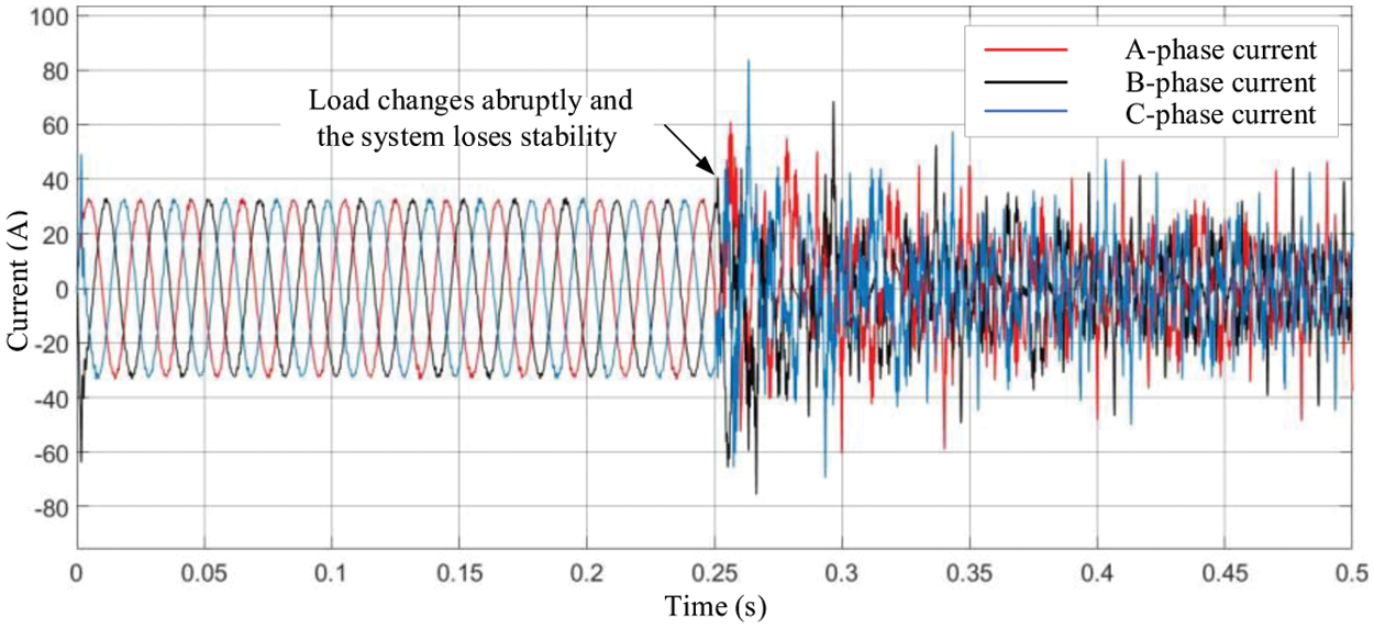
Figure 13: Grid-connected current waveform
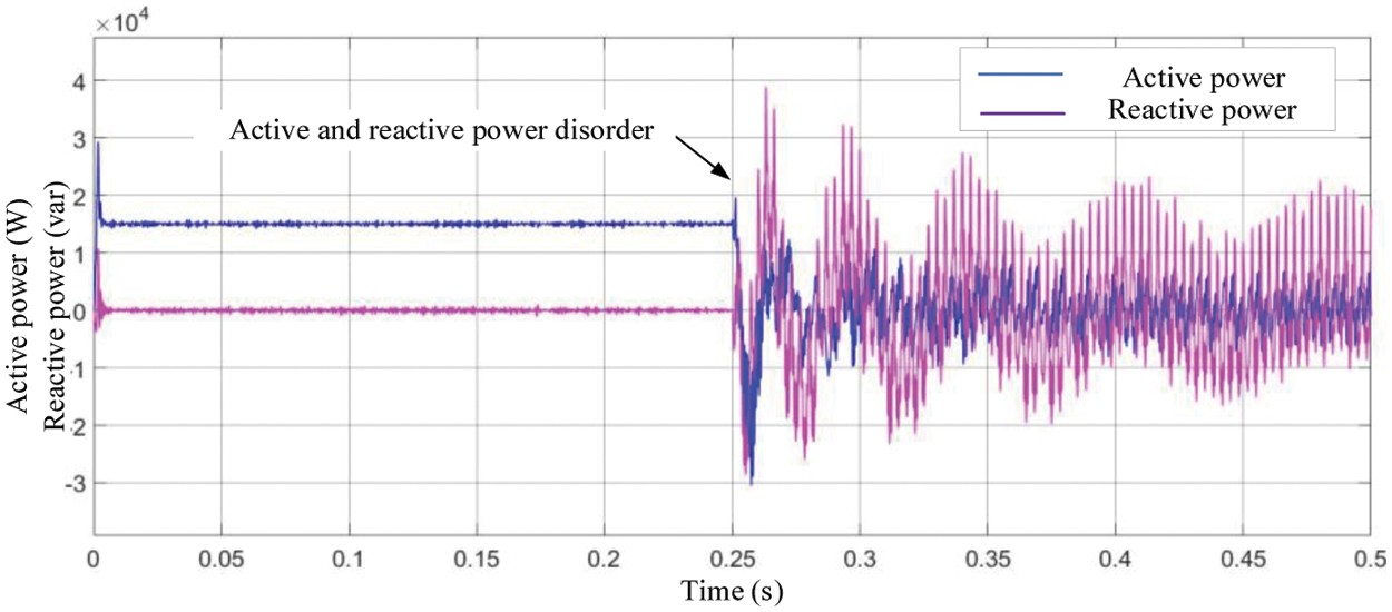
Figure 14: Active and reactive power
If the parameters designed in this paper are taken,
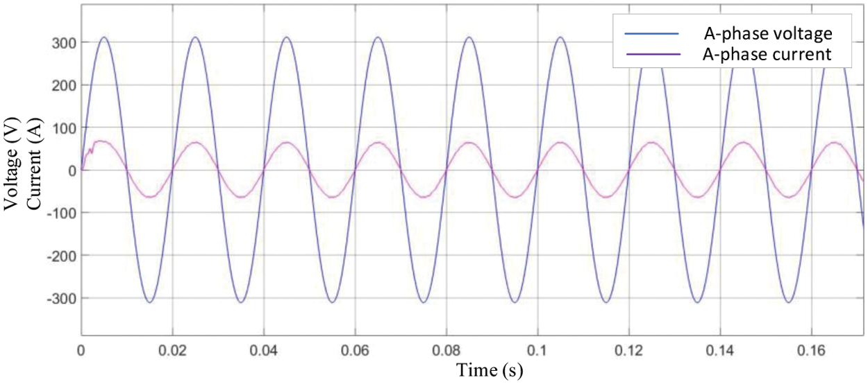
Figure 15: Phase A voltage and current
The waveform of 5 cycles starting from the grid-connected current 0.25 s is taken for harmonic analysis. Its Phase A harmonic analysis is shown in the Fig. 16.
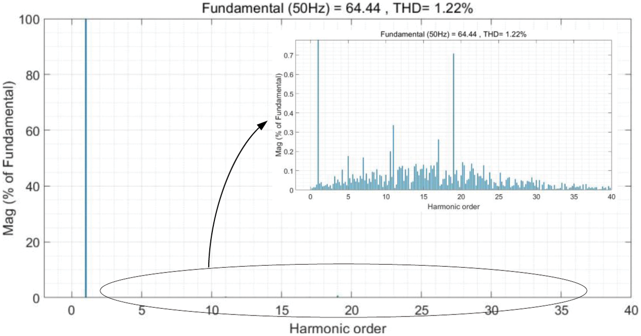
Figure 16: Phase A current harmonic analysis
The inverter is put into half-load from zero state, and is put into full-load operation at 0.25 s. The grid-connected current waveform is shown in Fig. 17, and the active and reactive power is shown in Fig. 18. The system is in a stable state at the beginning, but can quickly enter a stable state after full load operation, and the dynamic response of the system meets the requirements.

Figure 17: Grid-connected current waveform
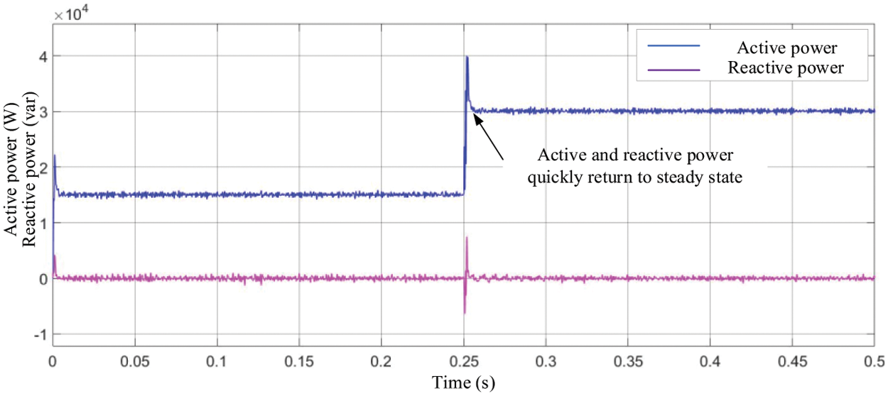
Figure 18: Active and reactive power
Under other working conditions, whether it is the load current fluctuation or voltage fluctuation of the power grid, the system can still reach stable condition quickly by using the control method in this paper. And the system overshoot and adjustment time are to meet the requirements.
(1) The grid voltage drops to 20% of the normal value at 0.1 s and returns to the normal value at 0.2 s. The phase A voltage and current are shown in the Fig. 19.
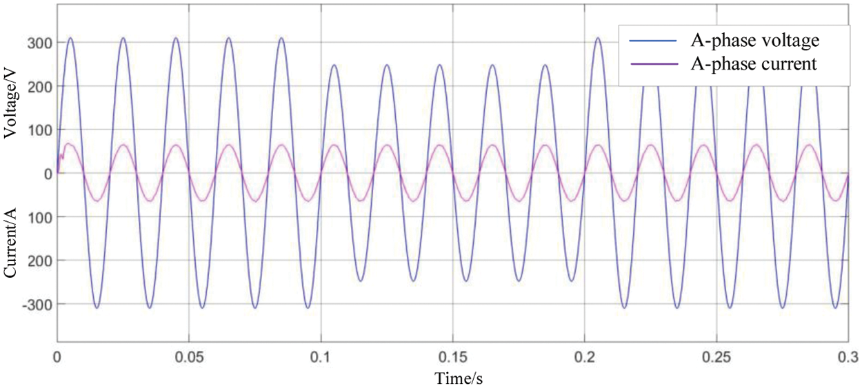
Figure 19: Phase A voltage and current
The grid current component in the d and q axis is shown in the Fig. 20.
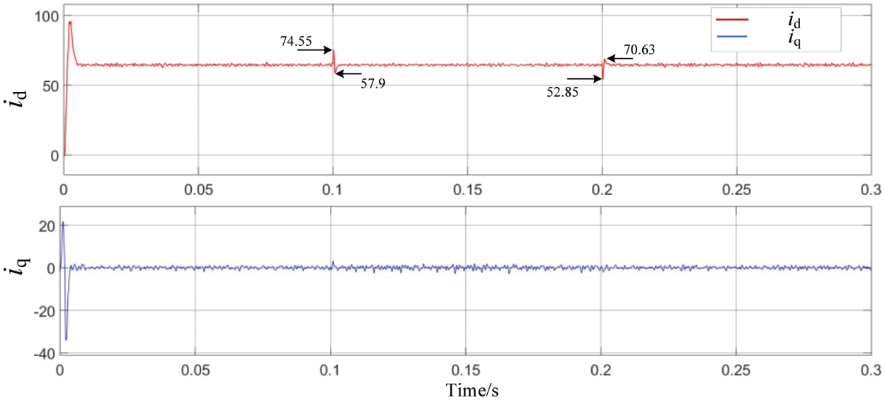
Figure 20: id and iq
(2) The grid voltage increases by 20% of the normal value at 0.1 s and returns to the normal value at 0.2 s. The Phase A voltage and current are shown in the Fig. 21.
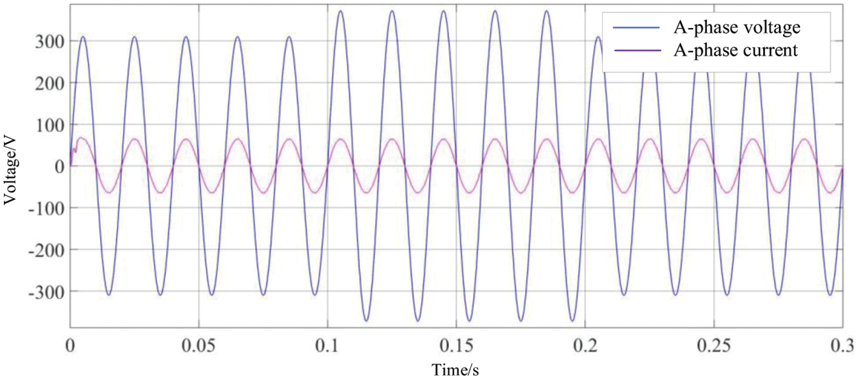
Figure 21: Phase A voltage and current
The grid current component in the d and q axis is shown in the Fig. 22.
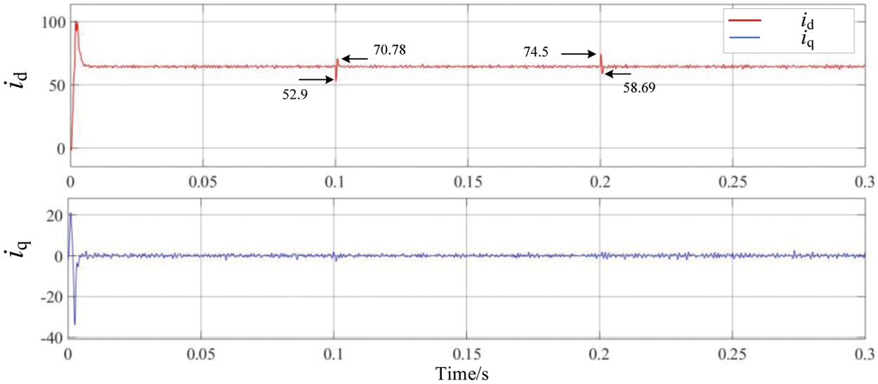
Figure 22: id and iq
(3) When the load changes from full load to half load, the phase A voltage and current are shown in the Fig. 23.
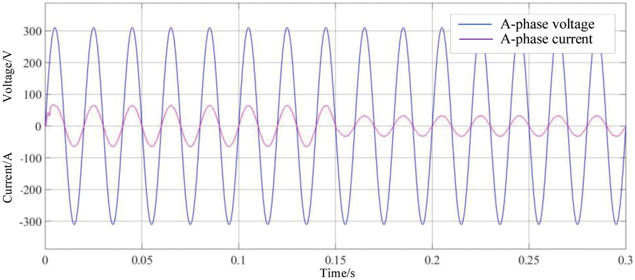
Figure 23: Phase A voltage and current
The grid current component in the d and q axis is shown in the Fig. 24.
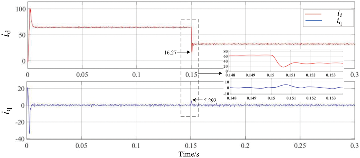
Figure 24: id and iq
As it can be seen from the figure above, under the double closed-loop current control, when the voltage of grid drops, the maximum variation of id is 10.09 A, and when the voltage of the grid rises, the maximum variation of id is 11.63 A. The time to reach the stable value is within 2 ms. When the grid voltage is disturbed to different degrees, it can still reach stability in a very short time.
In this paper, a T-type three-level grid-connected inverter is used as the interface between the distributed power supply and the power grid, and the parameter design of the current double closed-loop control system is given, and the grid-connected control strategy is simulated. In this paper, active damping is used as the inner loop, which can suppress the resonant peak of LCL filter without increasing the loss. The parameter design of controller based on baud diagram can not only have good stability performance, but also have good dynamic response performance. The simulation results show that the T-type three-level inverter has stable grid-connected voltage and current, low harmonic distortion, and good grid-connected effect, which verifies the feasibility and effectiveness of the control method above, and indicates that the control strategy can effectively reduce the grid-connected current harmonics and achieve high power factor grid-connected.
Funding Statement: Supported by Science and Technology Projects of State Grid Corporation of China (J2022019).
Conflicts of Interest: The authors declare that they have no conflicts of interest to report regarding the present study.
References
1. Yang, R. L. (2019). Research on control strategy of three-level grid-connected inverter under non-ideal grid conditions (Master Thesis). Chongqing University of Technology, Chongqing, China. [Google Scholar]
2. Nabae, A., Takahashi, I., Akagi, H. (1981). A new neutral-point-clamped PWM inverter. IEEE Transactions on Industry Applications, IA-17(5), 518–523. https://doi.org/10.1109/TIA.1981.4503992 [Google Scholar] [CrossRef]
3. Xing, X. Y., Chen, A. L., Wang, W. S., Du, C. (2015). Space-vector-modulated for Z-source three-level T-type converter with neutral voltage balancing. IEEE Applied Power Electronics Conference and Exposition (APEC), pp. 833–840. Charlotte, NC. [Google Scholar]
4. Schweizer, M., Kolar, J. W. (2013). Design and implementation of a highly efficient three-level T-type converter for low-voltage applications. IEEE Transactions on Power Electronics, 28(2), 899–907. https://doi.org/10.1109/TPEL.2012.2203151 [Google Scholar] [CrossRef]
5. Choi, U. M., Lee, K. B., Blaabjerg, F. (2014). Diagnosis and tolerant strategy of an open-switch fault for T-type three-level inverter systems. IEEE Transactions on Industry Applications, 50(1), 495–508. https://doi.org/10.1109/TIA.2013.2269531 [Google Scholar] [CrossRef]
6. Li, H. R., Yang, X. H., Wang, Y. N., Feng, C. C. (2015). Research on three-phase inverter based on fuzzy PI control of parameter self-adjustment and repetitive control. Electric Machines & Control Application, 42(2), 31–36. [Google Scholar]
7. Liu, X. D., Wu, J., Liu, S. C. (2014). A current control strategy of three-phase grid-connected inverter with LCL filter based on one-cycle control. International Conference on Electrical Machines and Systems, pp. 939–943. Hangzhou, China. [Google Scholar]
8. Xu, J. M., Xie, S. J., Zhang, B. F. (2015). Overview of current control techniques for grid-connected inverters with LCL filters in distributed power generation systems. Proceedings of CSEE, 35, 4153–4166. [Google Scholar]
9. Liu, T., Hao, X., Yang, X. (2012). A novel repetitive control scheme for three-phase grid-connected inverter with LCL filters. Power Electronics and Motion Control Conference, pp. 335–339. Harbin, China. [Google Scholar]
10. Zhang, H., Guo, T., Wang, J., Li, Z., Hu, K. (2022). Model predictive control and experimental study of LCL three-level grid-connected inverter. Research and Exploration in Laboratory, 41(3), 99–105. [Google Scholar]
11. Liang, H., Zhang, Q., Tang, Y., Li, C. (2022). Research on repetitive control strategy for harmonic suppression of grid-connected inverter. Power Electronics, 56(9), 5–7. [Google Scholar]
12. Xiong, Y. B. (2020). Research of QPR control strategy of LCL type grid-connected inverter (Master Thesis). Nanchang University, Nanchang, China. [Google Scholar]
13. Huang, X. B. (2014). Study on LCL filter in grid-tied inverter (Master Thesis). Nanjing University of Aeronautics & Astronautics, Nanjing, China. [Google Scholar]
14. Yang, X. D. (2017). Research on three-level grid-connected inverter with LCL filter (Master Thesis). Chongqing University of Technology, Chongqing, China. [Google Scholar]
15. Yi, T., Poh Chiang, L., Peng, W., Fook Hong, C., Feng, G. (2012). Exploring inherent damping characteristic of LCL-filters for three-phase grid-connected voltage source inverters. IEEE Transactions on Power Electronics, 27(3), 1433–1443. [Google Scholar]
16. Wang, X., Ruan, X., Liu, S. (2011). Full feed forward of grid voltage for grid-connected inverter with LCL filter to suppress current distortion due to grid voltage harmonics. IEEE Transactions on Power Electronics, 25(12), 3119–3127. https://doi.org/10.1109/TPEL.2010.2077312 [Google Scholar] [CrossRef]
17. Bao, C., Ruan, X., Wang, X. (2013). Step-by-step controller design for LCL-type grid-connected inverter with capacitor-current-feedback active-damping. IEEE Transactions on Power Electronics, 29(3), 1239–1253. [Google Scholar]
18. Sun, Y. D. (2015). Research on LCL-type grid-connected inverters control system (Master Thesis). Jiangsu University, Jiangsu, China. [Google Scholar]
19. Cai, K. W. (2014). Research of control strategy of micro-grid invert based on LCL filter (Master Thesis). Dalian University of Technology, Liaoning, China. [Google Scholar]
Cite This Article
 Copyright © 2023 The Author(s). Published by Tech Science Press.
This work is licensed under a Creative Commons Attribution 4.0 International License , which permits unrestricted use, distribution, and reproduction in any medium, provided the original work is properly cited.
 Downloads
 Citation Tools