
 Submit a Paper
 Propose a Special lssue
 Open Access
ARTICLE

Power Optimization Cooperative Control Strategy for Flexible Fast Interconnection Device with Energy Storage
1 Electric Power Research Institute, State Grid Jiangsu Electric Power Co., Ltd., Nanjing, 211103, China
2 Equipment Management Department, State Grid Jiangsu Electric Power Co., Ltd., Nanjing, 210029, China
3 Kunshan Power Supply Company, State Grid Jiangsu Electric Power Co., Ltd., Suzhou, 215300, China
* Corresponding Author: Mingming Shi. Email:
Energy Engineering 2023, 120(8), 1885-1897. https://doi.org/10.32604/ee.2023.025788
Received 11 August 2022; Accepted 02 November 2022; Issue published 05 June 2023
 View Full Text
 Download PDF
Abstract
With the wide application of renewable energy power generation technology, the distribution network presents the characteristics of multi-source and complex structure. There are potential risks in the stability of power system, and the problem of power quality is becoming more and more serious. This paper studies and proposes a power optimization cooperative control strategy for flexible fast interconnection device with energy storage, which combines the flexible interconnection technology with the energy storage device. The primary technology is to regulate the active and reactive power of the converter. By comparing the actual power value of the converter with the reference value, the proportional integral (PI) controller is used for correction, and the current components of d and q axes are obtained and input to the converter as the reference value of the current inner loop. The control strategy in this paper can realize power mutual aid between feeders, and at the same time, the energy storage device can provide or absorb a certain amount of power for feeders, so that the power grid can realize stable operation in a certain range.Keywords
In recent years, with the rapid development of renewable energy power generation technology based on wind and light energy and the wide application of distributed generation, the distribution network presents the characteristics of multi-source and complex structure [1]. Renewable energy power generation has factors such as volatility, mutation and uncertainty. A large number of fast, low inertia and high-frequency power electronic systems are widely connected to low-speed, high inertia and power frequency power systems, which gradually reduces the proportion of thermal motor assemblers, and the rotating reserve capacity is relatively reduced. The power system is increasingly characterized by a high proportion of renewable energy, a high proportion of power electronics, and a high proportion of external electricity in the region, The power grid will gradually develop into a low inertia and underdamped network dominated by power electronic converters. Frequency and voltage transient control has become a potential risk affecting the stable operation of the power system. The problem of power quality has become increasingly obvious, becoming the biggest challenge for the safe and stable operation of the large power grid [2]. At the same time, the new random load low-voltage distribution network represented by electric vehicle charging piles will make the problem of power quality more serious.
Flexible interconnection technology is an important technology in active distribution network. Through flexible interconnection device, different areas in active distribution network can realize power mutual aid and realize flexible regulation of power flow between connected buses, and promote distribution network system to accept more distributed renewable energy. After adding the energy storage device, the flexible fast interconnection device with energy storage used in this paper can realize the power mutual aid between different feeders, and stabilize the power fluctuation within a certain range when the connected feeders cannot absorb or provide the corresponding power difference in time.
The idea of flexible interconnection is proposed mostly through the new power electronic equipment based on VSG, mainly including loop balance controller (LBC), loop power controller (LPC) [3], energy router (ER) [4–6] and soft normally open point (SNOP) [7,8] and other equipment.
Many scholars have studied the distribution network flexible interconnection switch scheme with flexible interconnection equipment as the connection port between different feeders. In 2001, Nippon Electric Power Industry Research Institute proposed to connect the feeders of distribution network in the form of ring network through LPC, and realize the mutual aid of power flow between different distribution network partitions by using the independent control based on local voltage information [9]. In 2007, it also developed the miniaturized equipment of LPC by using LBC, and completed the device operation and demonstration application [10]. In 2007, Eindhoven University of Technology in the Netherlands proposed the concept of intelligent node (IN) and applied it to power flow optimization in distribution networks [11]. In 2009, Serbian Institute of technology in Spain connected DC links between distribution feeders, studied the advantages of DC links in reducing distribution network losses, balancing feeder loads and improving the permeability of distributed power, and developed an optimization method to determine the optimal configuration of DC links variables [12]. In 2010, Imperial College of Technology proposed the concept of SNOP to replace the normally open switch in the traditional distribution network, so that the distribution network has the operation advantages of both radial and ring network structures at the same time. The experimental results show that SNOP can greatly improve the penetration of distributed power in the distribution network [13].
Reference connected the energy storage to the back-to-back voltage source converter through the DC-DC converter based on the double active bridge structure, and proposed a global control strategy for the energy storage flexible interconnection equipment [14], which realized the active and reactive output control of the converters on both sides. Although it improved the control flexibility of the energy storage flexible interconnection equipment, this control strategy is more complex. Reference took IEEE-33 node as the platform, used energy storage flexible interconnection equipment to connect 18 and 33 nodes, and proposed multi time scale optimization, taking eliminating the power fluctuation of distributed generation as the objective function, and dynamically adjusted the power output value of converters and energy storage devices on both sides. The results showed that flexible interconnection equipment with energy storage devices had advantages in dealing with power transients and improving voltage distribution. Reference analyzed the control strategy of flexible distribution network based on multi terminal intelligent soft open point (SOP), and selected droop control with high reliability as the overall control strategy of flexible distribution network. Although it improves the reliability of urban distribution network, it cannot solve the problem of lack of load balancing and renewable energy consumption.
Aiming at the problems of lack of flexibility and rapidity in the control strategy of flexible interconnection devices in the existing research and the optimization of the control strategy of flexible interconnection devices, this paper proposes a power optimization cooperative control strategy for flexible fast interconnection device with energy storage. The application of energy storage technology can realize the collaborative optimization of energy at all ends of the distribution network, effectively achieve demand side energy management, renewable energy consumption, improve the system operation economy, and improve the power quality. At the same time, the supercapacitor has high power density, many cycles and fast response speed, which is suitable for short-term high-power demand scenarios. The control strategy of energy storage device is added in this paper, which can effectively save transmission time in power supply reliability; In terms of personal and equipment security, since there is no need for on-site personnel to operate, the security of switching operation will be greatly improved after the flexible interconnection is realized. And it can effectively solve the problems of resource interconnection and mutual supply in different regions, and mismatch between power resources and load demand. Facing the traditional distribution network, it can realize the power mutual aid of different feeders, and the energy storage device can also provide active and reactive power support. At the same time, the working state of the whole system is controlled by adjusting the energy storage device and power electronic converter, so as to realize the comprehensive allocation and management of electric energy, and realize the optimal collaborative control of flexible fast interconnection devices with energy storage.
2 Architecture of Flexible Fast Interconnection Device
The structure diagram of the flexible fast interconnection device with energy storage studied in this paper is shown in Fig. 1. The flexible interconnection device is connected to feeder 1 and feeder 2 through back-to-back voltage source converter (BTB-VSC), and the supercapacitor is connected to the DC side of the flexible interconnection device through bidirectional DC converter, and connected to the AC system through the flexible interconnection device. The control methods adopted by the two converters are P-Q control. According to the actual power of the AC side of feeder 1 and feeder 2, the active power and reactive power reference values are set respectively, and the control signals are obtained by comparing the active and reactive power reference values with the actual values to control the two converters and realize the function of power mutual aid.
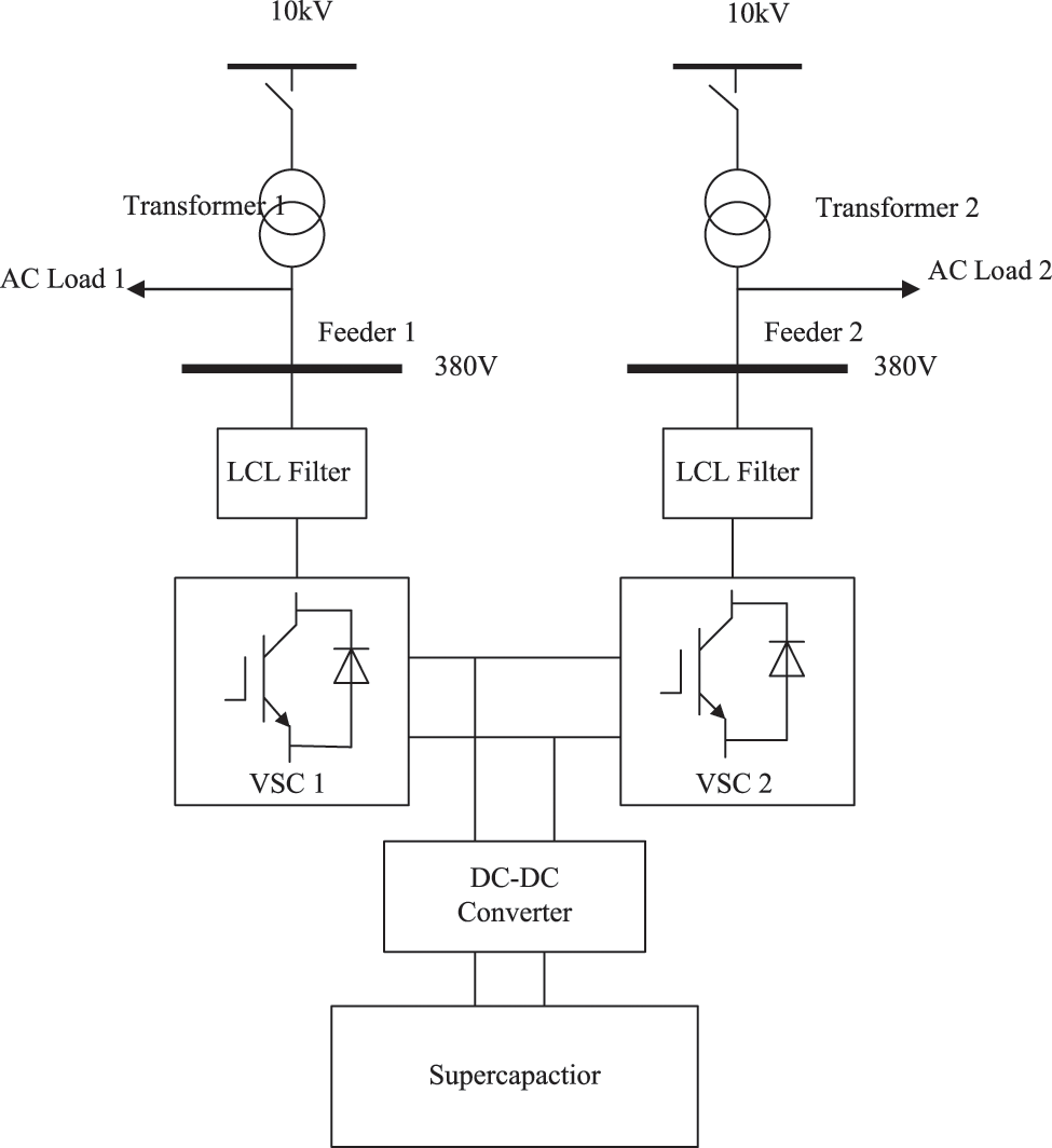
Figure 1: Structure diagram of flexible fast interconnection device with energy storage
It is specified that the active power reference value of converter 1 is
The flexible interconnection device can realize the following three functions:
Funtion1: Power mutual aid
When
Funtion2: Active and reactive power support (supercapacitor discharging)
When
Funtion3: Active and reactive power support (supercapacitor charging)
When
3 Design of Power Optimization Cooperative Control Strategy
The power control function diagram of the flexible fast interconnection device is shown in Fig. 2.
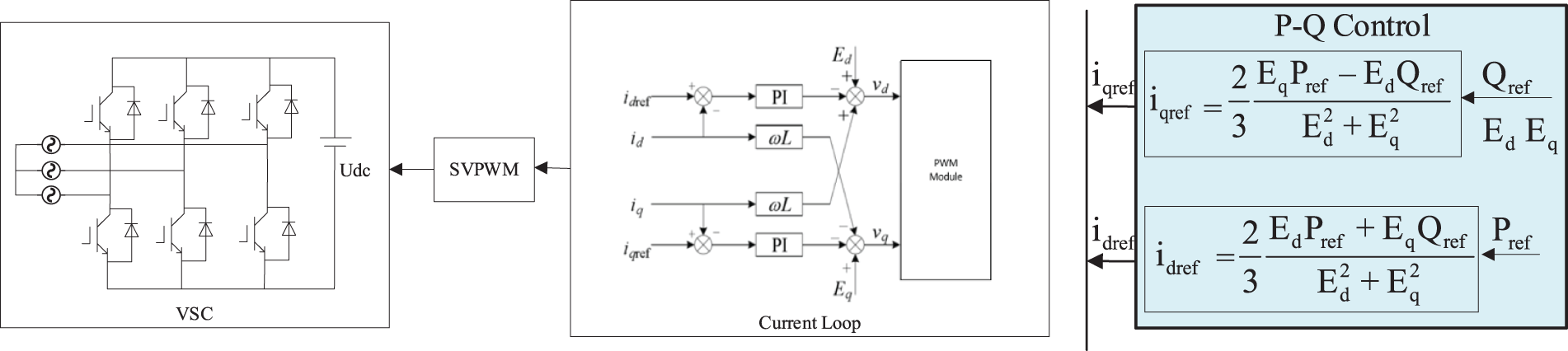
Figure 2: Power control function diagram
The power mutual aid, active and reactive power support of the system depend on the accurate control of the output active and reactive power of the port converter, that is, P–Q control of the port.
Eq. (1) shows that when the AC system voltages
The governing equation is as Eq. (2):
In Eq. (2):
As shown in Fig. 3, when
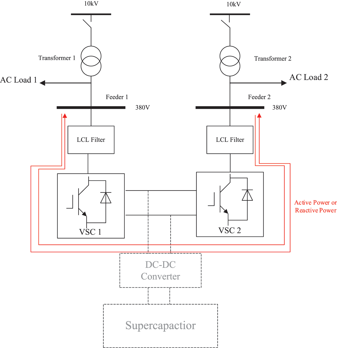
Figure 3: Power flow diagram of power mutual aid control
As shown in Fig. 4, when
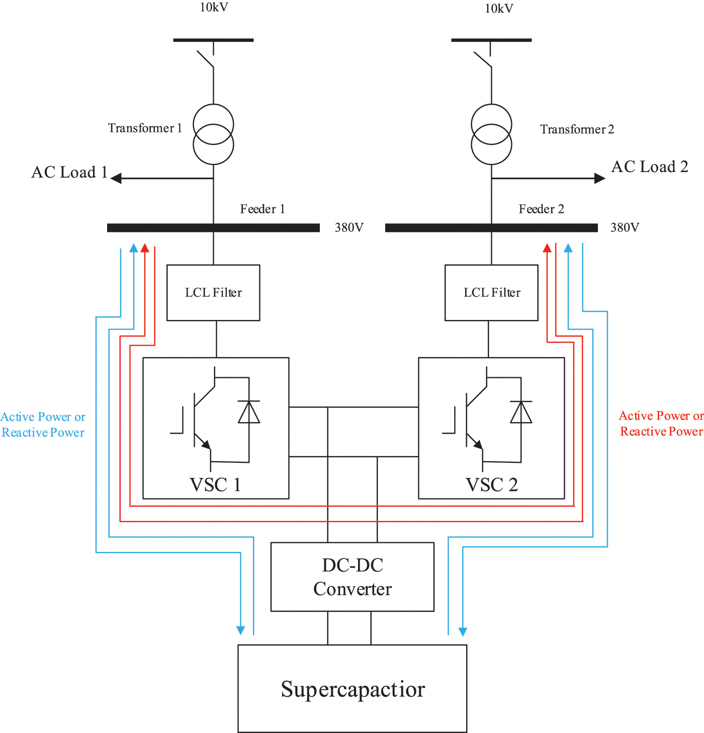
Figure 4: Power flow diagram of active and reactive power support
In order to verify the effectiveness of the control strategy proposed in this paper, a simulation model is established in MATLAB/Simulink environment, as shown in Fig. 5, and the simulation parameters are shown in Table 1 below.
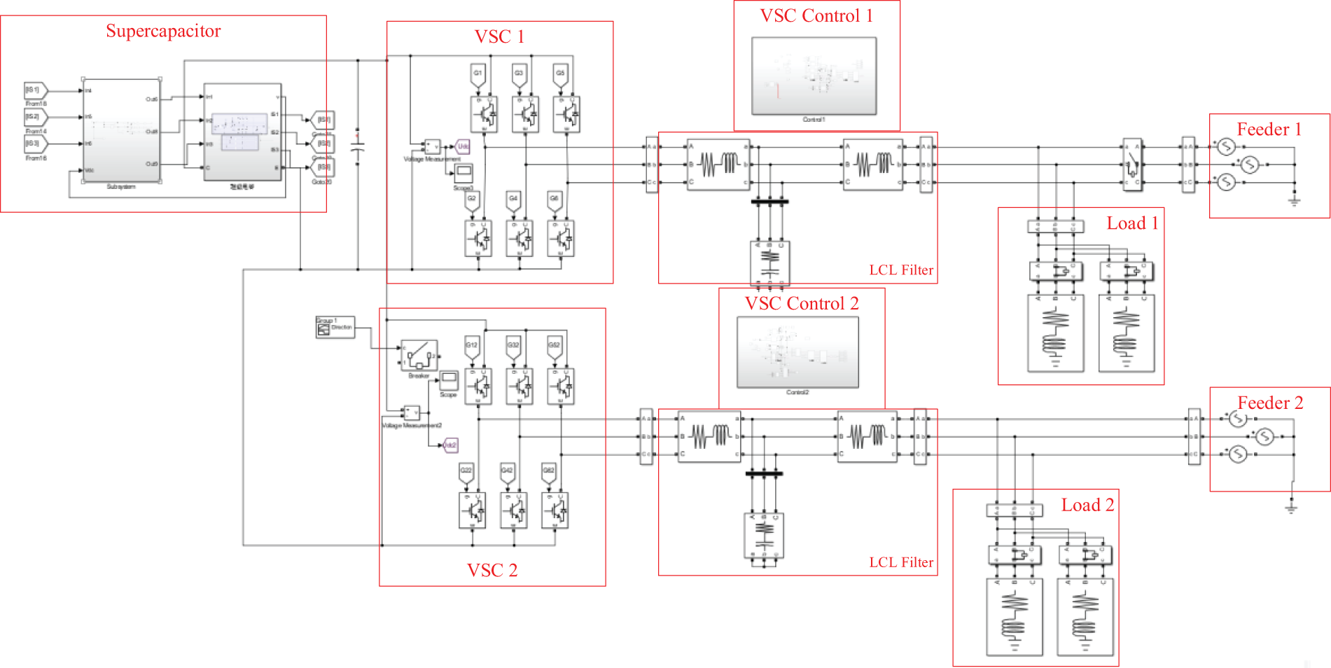
Figure 5: Simulation model of flexible fast interconnection device with energy storage

Among them, the supercapacitor energy storage capacity is determined by the voltage level and support time according to the project requirements. See the Funding Statement at the end of the text for specific projects.
In order to verify that the flexible interconnection device can realize the function of power mutual aid, simulation verification is designed. At 0.1 s, the active power of feeder 1 with load is 40 kW, and the reactive power is 20 kvar; feeder 2 has load active power of 40 kW and reactive power of 20 kvar. At 0.3 s, feeder 1 suddenly increases the load active power of 30 kW and reactive power of 30 kvar; the load power of feeder 2 remains unchanged, and the supercapacitor does not participate. The waveforms of VSC output power, feeder output power, feeder load power and supercapacitor state are measured, respectively, as shown in Fig. 6.
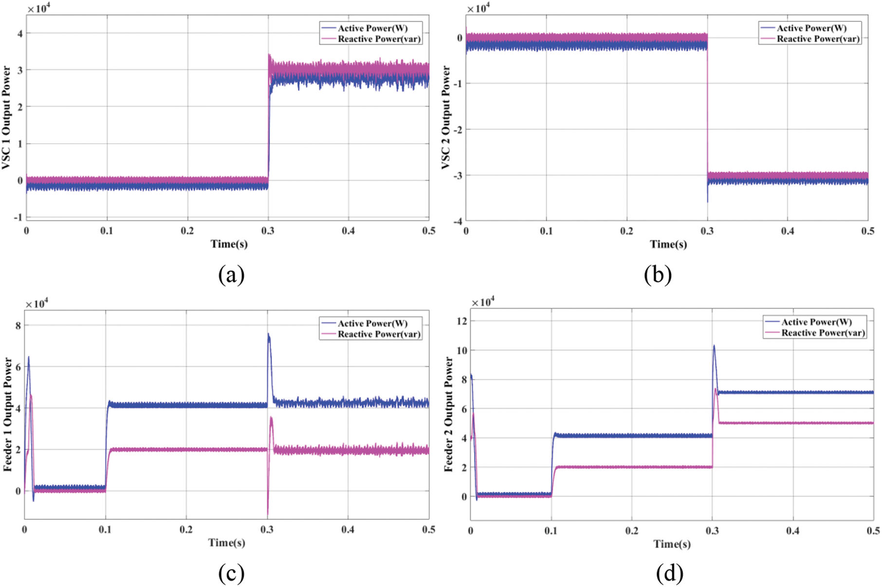
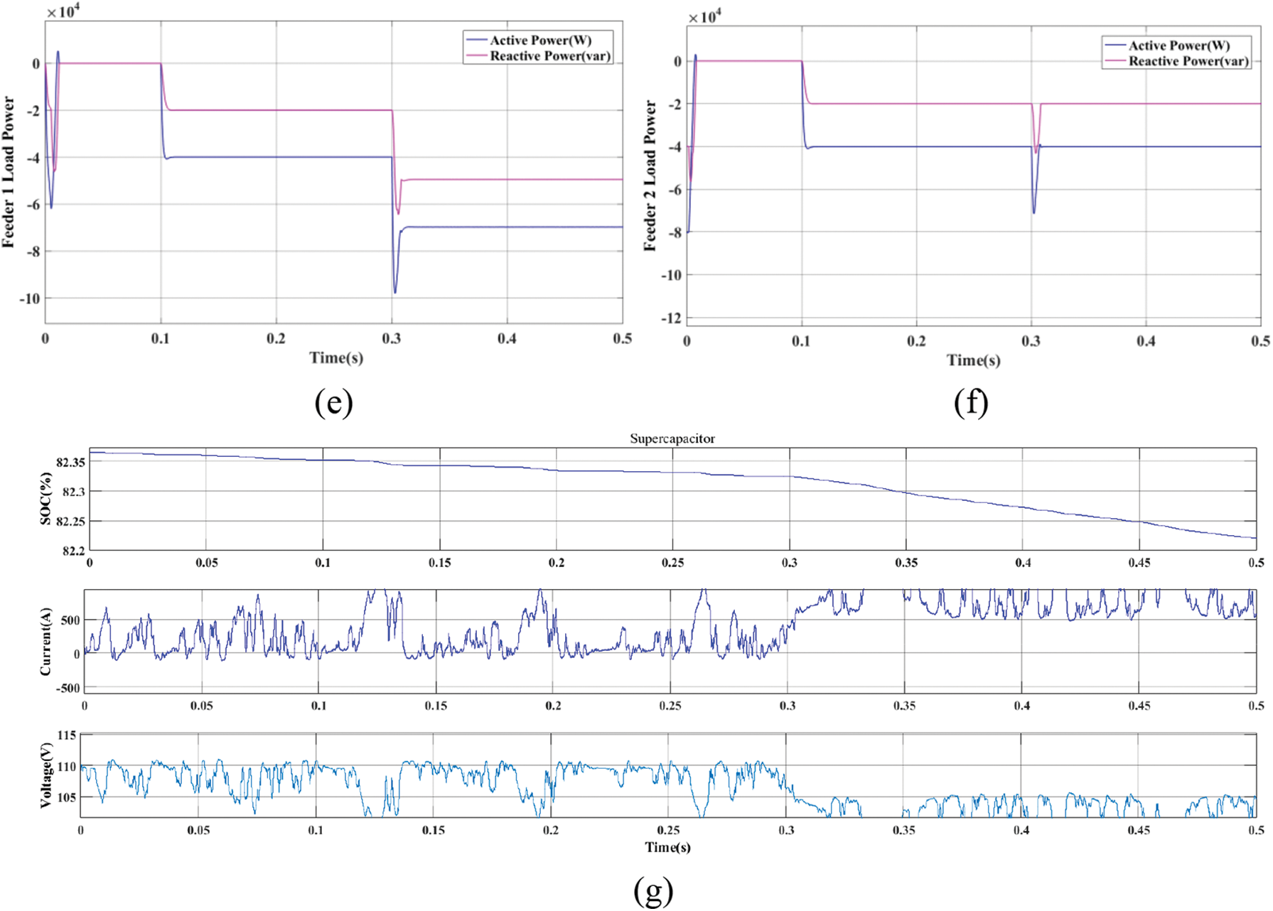
Figure 6: Power mutual aid simulation (a) VSC 1 output power (b) VSC 2 output power (c) Feeder 1 output power (d) Feeder 2 output power (e) Feeder 1 load power (f) Feeder 2 load power (g) Supercapacitor working condition
According to the above simulation, the supercapacitor does not provide power to feeder 1 and feeder 2 at 0.1 s, and feeder 1 and feeder 2 provide active power of 40 kW and reactive power of 20 kvar, respectively; at 0.3 s, the sudden load power of feeder 1 is provided by feeder 2. When the supercapacitor is not involved, the flexible fast interconnection device can realize the power mutual aid function between the two converters, solve the problems brought by renewable energy power generation to the power system, and help maintain the stability of the power grid.
4.2 Active and Reactive Power Support
In order to verify that the flexible interconnection device can realize the function of active and reactive power support, two simulation verifications of supercapacitor charging and discharging are designed, respectively.
When at working condition 1:0.1 s, the active power of feeder 1 with load is 40 kW, and the reactive power is 20 kvar; feeder 2 has load active power of 40 kW and reactive power of 20 kvar.
At 0.3 s, feeder 1 and feeder 2 suddenly increase the load active power of 30 kW, and the supercapacitor discharges. The waveforms of VSC output power, feeder output power, feeder load power and supercapacitor state are measured, respectively, as shown in Fig. 7.
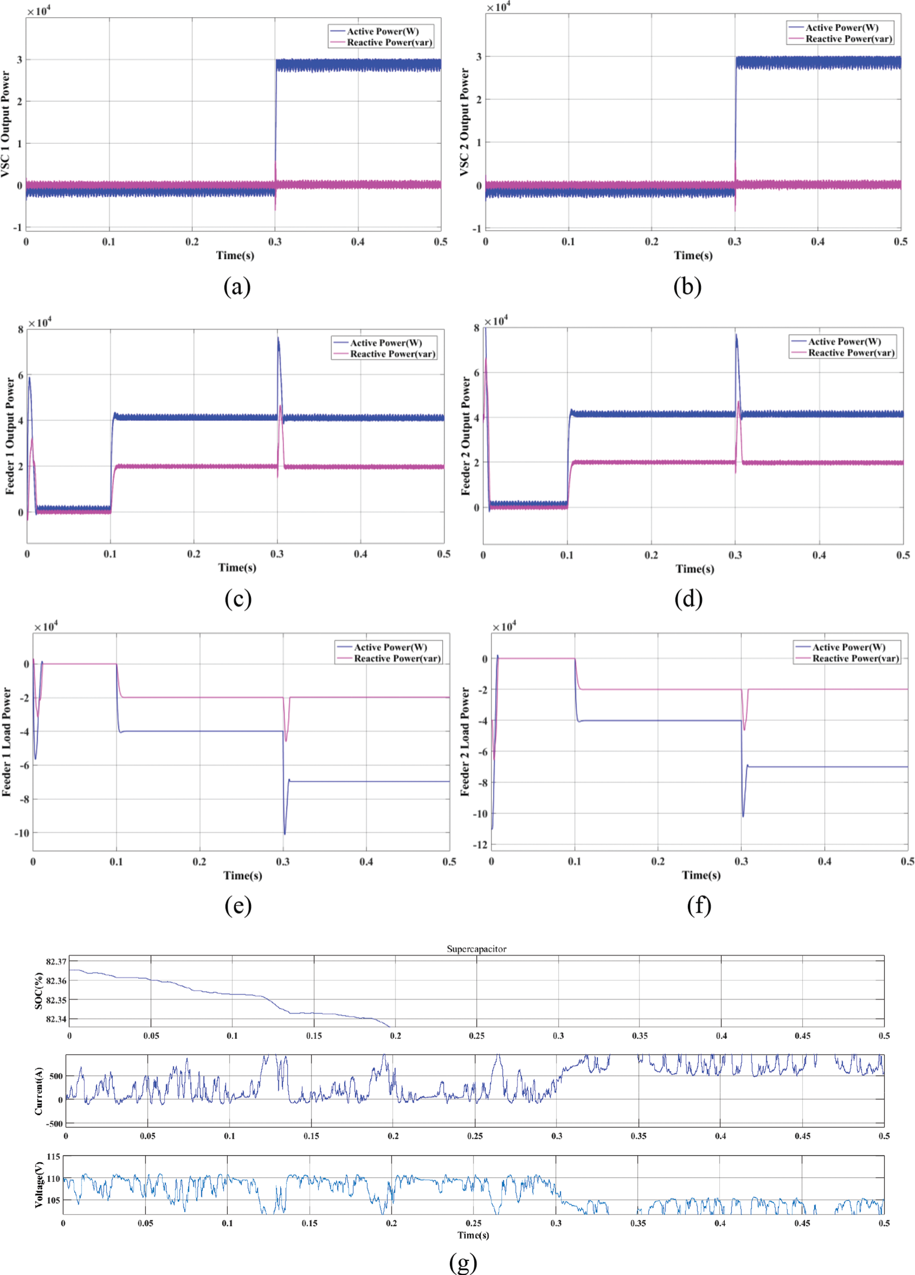
Figure 7: Active and reactive power support simulation (condition 1) (a) VSC 1 output power (b) VSC 2 output power (c) Feeder 1 output power (d) Feeder 2 output power (e) Feeder 1 load power (f) Feeder 2 load power (g) Supercapacitor working condition
According to the above simulation, the supercapacitor does not provide power to feeder 1 and feeder 2 at 0.1 s. Feeder 1 and feeder 2 provide active power of 40 kW; at 0.3 s, the active power of sudden load increase of feeder 1 and feeder 2 is provided by supercapacitor.
When at working condition 2:0.1 s, the active power of feeder 1 with load is 40 kW and the reactive power is 20 kvar; feeder 2 has load active power of 40 kW and reactive power of 20 kvar. At 0.3 s, feeder 1 suddenly increases the load active power of 10 kW and reactive power of 10 kvar; feeder 2 with load power unchanged, supercapacitor charging. The waveforms of VSC output power, feeder output power, feeder load power and supercapacitor state are measured, respectively, as shown in Fig. 8.
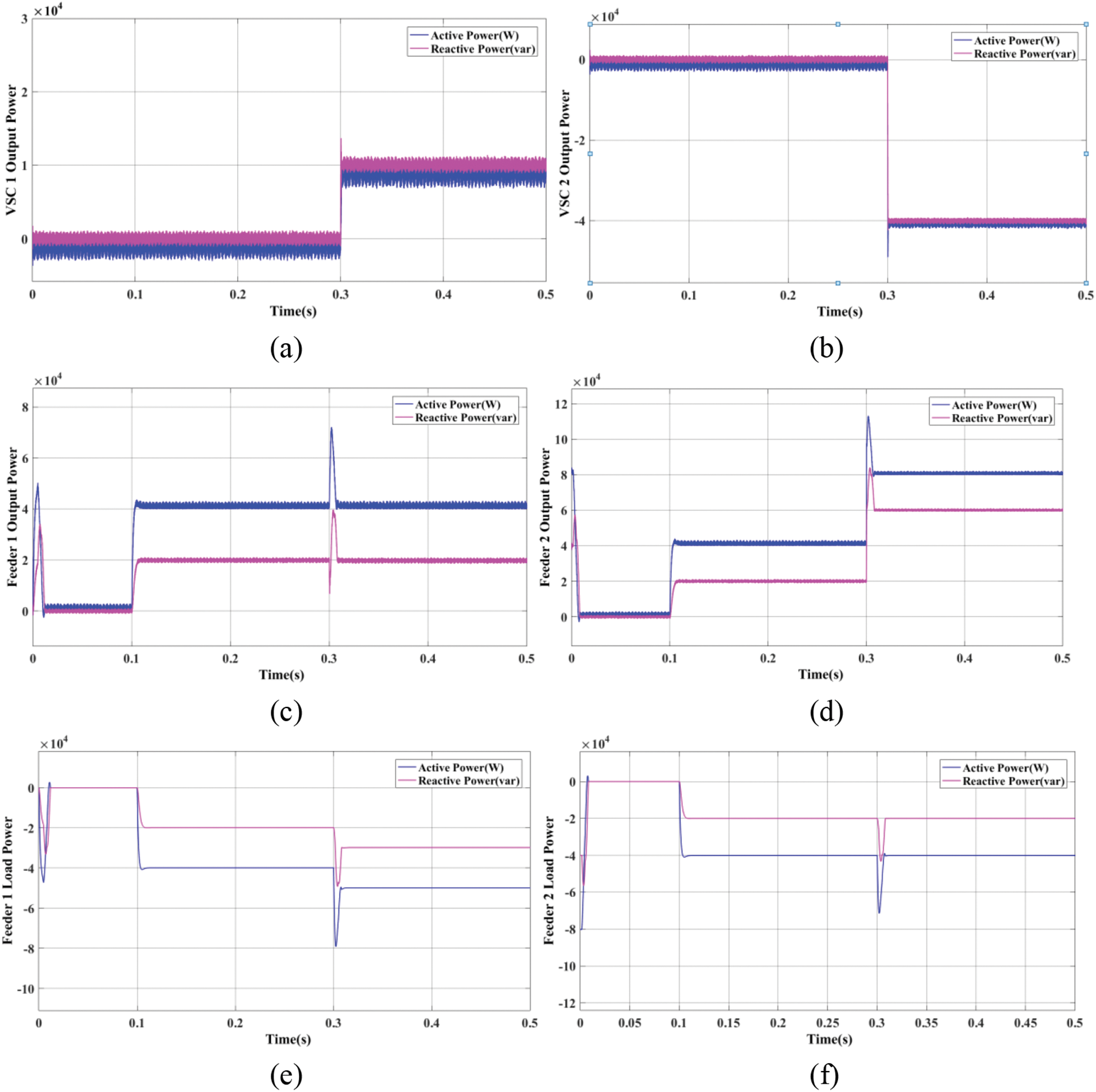
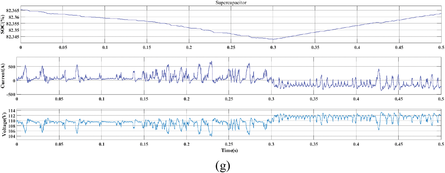
Figure 8: Active and reactive power support simulation (condition 2) (a) VSC 1 output power (b) VSC 2 output power (c) Feeder 1 output power (d) Feeder 2 output power (e) Feeder 1 load power (f) Feeder 2 load power (g) Supercapacitor working condition
According to the above simulation, the supercapacitor does not provide power to feeder 1 and feeder 2 at 0.1 s. Feeder 1 and feeder 2 provide active power of 40 kW and reactive power of 20 kvar respectively; At 0.3 s, the active and reactive power of the sudden increase load of feeder 1 is provided by feeder 2, and the excess energy of feeder 2 is stored in the supercapacitor to charge the supercapacitor.
From the above two different working conditions, it can be seen that adding energy storage devices, while the power mutual aid between feeders, the energy that cannot be absorbed or provided by feeders can be stored or released by the energy storage device, so as to achieve the stability of power within a certain range and greatly improve the stability of the power grid.
Aiming at the power system instability and power quality problems caused by the increase of renewable energy generation, this paper proposes a power optimization collaborative control strategy for flexible fast interconnection devices with energy storage. The primary technology is the P–Q control of VSC, which compares the actual value of active and reactive power of VSC with the reference value, inputs the compared value to the PI controller for correction, obtains the current component of d and q axis, and inputs it to VSC as the reference value of the internal current loop to realize the corresponding control requirements. First, it can realize the power mutual aid between feeders without the participation of energy storage devices, and the two power grids cooperate with each other to achieve a certain range of stable operation. At the same time, when the energy storage device participates in the power mutual aid between feeders, it can realize the function of providing or absorbing excess power for feeders, improving the utilization rate of electric energy and strengthening the stable operation ability of the power grid.
But in the future, more parts need to be improved than the efficiency of such control strategies. Efficiency plays a crucial role in the practical application of control strategies, and the research on improving control strategies will also be carried out in the future. In addition, the capacity of the supercapacitor will be further optimized in the future, so that it can be used in different scenarios, and the performance of the control strategy can be further improved.
Funding Statement: Supported by Science and Technology Projects of State Grid Corporation of China (JF2021018).
Conflicts of Interest: The authors declare that they have no conflicts of interest to report regarding the present study.
References
1. Zhu, Y. (2019). Research on power supply fast switching technology based on three-port flexible multi-state switch (Master Thesis). Hefei University of Technology, Anhui, China. [Google Scholar]
2. Wang, C. (2015). Development and challenges of intelligent distribution system. Distribution & Utilization, 2, 43–44. [Google Scholar]
3. Chen, C. S., Tsai, C. T., Lin, C. H., Hsieh, W. L., Ku, T. (2011). Loading balance of distribution feeders with loop power controllers considering photovoltaic generation. IEEE Transactions on Power Systems, 26(3), 1762–1768. https://doi.org/10.1109/TPWRS.2010.2102052 [Google Scholar] [CrossRef]
4. Nguyen, P. H., Kling, W. L., Ribeiro, P. F. (2011). Smart power router: A flexible agent-based converter interface in active distribution networks. IEEE Transactions on Smart Grid, 2(3), 487–495. https://doi.org/10.1109/TSG.2011.2159405 [Google Scholar] [CrossRef]
5. Zhao, Z., Feng, G., Yuan, L., Zhang, C. (2017). The development and key technologies of electric energy router. Proceedings of the CSEE, 37(13), 3823–3834. [Google Scholar]
6. Ge, Q., Yao, G. (2019). Research status and prospects of electric energy router technology. Electric Power Construction, 40(6), 105–113. [Google Scholar]
7. Wang, A. (2015). Research on SNOP and its application in distribution network (Master Thesis). Beijing Jiaotong University, Beijing, China. [Google Scholar]
8. Gao, R. (2018). Research on flexible grid-connected interface control strategy of microgrid based on back-to-back converter (Master Thesis). Xi’an University of Technology, Xi’an, China. [Google Scholar]
9. Okada, N. (2001). Autonomous loop power flow control for distribution system. Seventh International Conference on AC-DC Power Transmission, pp. 150–155. London, UK. [Google Scholar]
10. Okada, N., Takasaki, M., Sakai, H., Katoh, S. (2007). Development of a 6.6 kV-1 MVA transformerless loop balance controller. 2007 Power Electronics Specialists Conference, pp. 1087–1091. Orlando, FL, USA. [Google Scholar]
11. Graaff, R., Myrzik, J., Kling, W. L., Enslin, J. (2007). Intelligent nodes in distribution systems-optimizing steady state settings. 2007 IEEE Lausanne Power Tech, pp. 391–395. Lausanne, Switzerland. [Google Scholar]
12. Maranomarcolini, A., Romeroramos, E., Gomezexposito, A., Mazaortega, J. M., Martinezramos, J. L. (2009). Enhancing the integration of renewable sources in distribution systems using DC-links. 2009 IEEE PES/IAS Conference on Sustainable Alternative Energy (SAE), pp. 1–5. Valencia, Spain. [Google Scholar]
13. Bloemink, J. M., Green, T. C. (2010). Increasing distributed generation penetration using soft normally-open points. IEEE PES General Meeting, pp. 1–8. Minneapolis, MN, USA. [Google Scholar]
14. Attanasio, F., Wasterlain, S., Pidancier, T., Marchesoni, M., Favre-Perrod, P. et al. (2018). Low voltage soft open point with energy storage: System simulation and prototype preliminary test results. 2018 International Symposium on Power Electronics, Electrical Drives, Automation and Motion (SPEEDAM), pp. 254–261. Amalfi, Italy. [Google Scholar]
Cite This Article
 Copyright © 2023 The Author(s). Published by Tech Science Press.
This work is licensed under a Creative Commons Attribution 4.0 International License , which permits unrestricted use, distribution, and reproduction in any medium, provided the original work is properly cited.
 Downloads
 Citation Tools