
 Submit a Paper
 Propose a Special lssue
 Open Access
ARTICLE
Enhanced Electric Power Adaptability Using Hybrid Pumped-Hydro Technology with Wind and Photovoltaic Integration
1 Department of Electrical Power Engineering, Durban University of Technology, Durban, 4001, South Africa
2 Department of Electrical, Electronics and Computer Engineering, Cape Peninsula University of Technology, Bellville, 7535, South Africa
* Corresponding Author: Abayomi A. Adebiyi. Email:
(This article belongs to the Special Issue: Advanced Heat Pump Technologies for Renewable Energy Utilization)
Energy Engineering 2023, 120(9), 1939-1961. https://doi.org/10.32604/ee.2023.027574
Received 04 November 2022; Accepted 17 May 2023; Issue published 03 August 2023
 View Full Text
 Download PDF
Abstract
The integration of solar and wind energy into the electrical grid has received global research attention due to their unpredictable characteristics. Because wind energy varies across all timescales of utility activity, renewable energy generation should be supplemented and enhanced, from real-time, minute-to-minute variations to annual alterations influencing long-term strategy. Wind energy generation does not only fluctuate but is also challenging to accurately forecast the timeframes of significance to electricity decision makers; day-ahead and long-term making plans of framework sufficiency such as meeting the network peak load annually. A utility that integrates wind and solar energy into its electricity mix would understand how to adapt to uncertainty and variability in operations while sustaining grid stability. Due to hydropower’s adaptability, a system using hydropower as one of its generating resources could be precisely adapted to absorb the variability of wind and solar energy. The objective of this research study is to create a hybrid system comprising hydro-wind and solar (Hybrid-HWS) integration for power balancing in an isolated electrical network in Klipkop village, Pretoria region, South Africa. The desirability of designing and building goaf storage tank in regard to capability, the fullness of line throughout water pumping, dispensing, storage tank spillage, and pressure difference throughout liquid flow within the storage tanks were preliminary assessed using geotechnical and weather forecasting data from a distinctive area of Klipkop town in Pretoria, South Africa. Different facility hours premised on daylight accessibility are scheduled to balance maximum load at early and late hours. However, in the scenario of electrical power, time shift requiring storage for extended periods of time, such as in terms of hours, Hybrid-HWS has been found to have a crucial role. The results of simulations showed a coordinated process design for Hybrid-HWS Energy Storage (ES) to determine everyday strategic planning in reducing the variability of the system resulting from wind-solar-pumped hydro ES output inadequacies and satisfy daily load demands. It could be recommended that by considering the adaptability characteristics, extremely rapidly, ramping, peaking support and maximum stabilizing aid of the system could be archived with pump-hydro into the energy mix which can provide specific guidelines for energy policymakers.Keywords
Nomenclature
| APM | Abandoned Pit Mines |
| ES | Energy Storage |
| Hybrid-HWS | Hybrid hydro-water and solar |
| PHS | Pumped hydro storage |
| PV | Photovoltaic |
| RE | Renewable Energy |
| UPSH | Underground Pumped Storage Hydro power |
Renewable Energy (RE) is playing an increasingly important role in the global electricity evolution since fossil power generation is comparatively expensive. Renewable energy could be a cheaper long-term option hence, alternative power sources must be harnessed largely in rural areas that have a significant percentage of non-renewable sources. The increasing use of RE might raise the need for the utilization of pump-hydro facilities, particularly large-scale ES technology. The transition from fossil fuel usage to RE is seen as an unavoidable concept to combat climate change, reduce pollution, and decrease reliance on crude oil. In line with the rapid development, numerous businesses around the world, particularly powerful corporate interests, had already spearheaded the use of green energy. The fact is that, so many businesses are embracing the concept of RE and getting concrete steps to expedite the switchover to clean energy sources which are regarded as a positive indication in the global attempts to develop a sustainable world. As a result, many nations have made initiatives to shift their electricity generation mindsets by vigorously integrating renewable energy sources (RESs), such as wind, solar photovoltaic (PV), bioenergy, and ocean wave energy, into their power generation mix [1]. The major issue with some renewable energy sources, such as solar and wind energy, is that they are intermittent and uncertain in nature and their generation over time cannot be matched to changes in load [2,3]. As a result, ES systems have emerged as a critical tool for increasing the capacity and production of renewable. A typical conceptual pumped hydro storage system with wind and solar power options for transferring water from the lower to the upper reservoir is represented as depicted in Fig. 1. This system includes a photovoltaic (PV) array, a wind turbine, an energy storage system (pumped-hydro storage), a control station, and an end-user interface (load). This entire system can be isolated from the grid, i.e., as a standalone system, or it can be connected to the grid, with the control station serving as the grid inertia capacity. Based on determining factors such as capital costs, suitable topography, and climate change challenges, this is currently the most cost-effective method of storing large amounts of renewable energy.
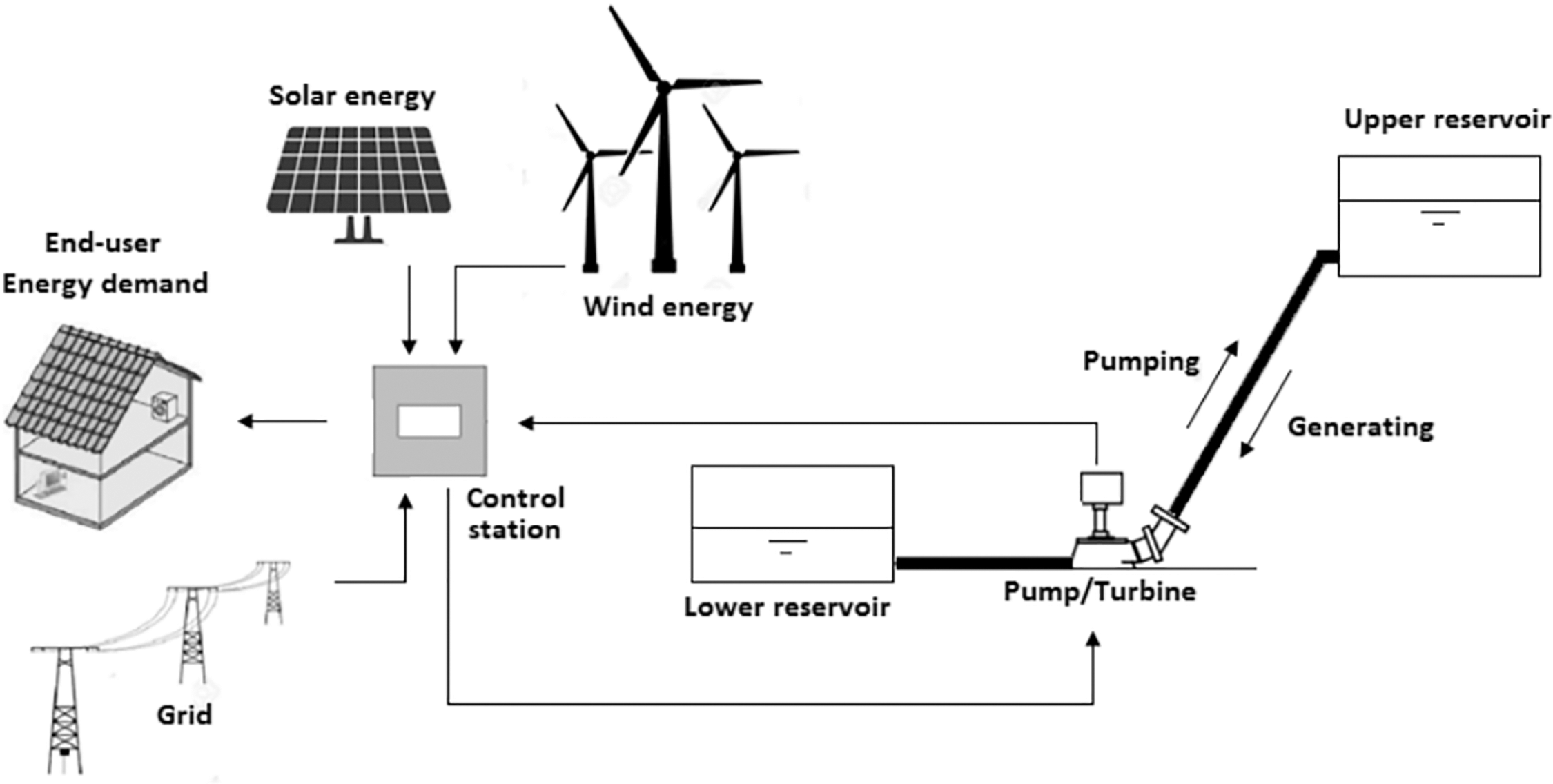
Figure 1: A hybrid hydro-wind-solar system with pumped storage system [4]
ES systems enable power generation to be controlled based on demand and can help the power system with inertia to achieve better grid reliability [5]. These technologies allow surplus power to be stored throughout the periods of minimum load while generating power during peak load. Pump Storage Hydropower (PSH) is a popular storage system since it enables huge amounts of power to be stored and generated when needed by using water and gravity. Pump-Hydro-Solar-Wind complementation can significantly decrease PV and wind fluctuations while also improving renewable energy utilization functionality [6]. It can give electricity systems more adaptability. This adaptability is critical for improving the consistency of electric power systems with increased uncertainty. In the United States, there are 40 PSH plants with an installed power of more than 22 GW accounting for approximately 2% of overall electricity production [7]. One of the most significant advantages a PSH draws to the network is that it stores surplus power, allowing reference power stations to remain operational and renewable to continue generating even when the net consumer is low. The percentage of costly shutting down and starting-up activities at any of those baseload-generating units can be significantly lowered. When required, the energy contained in a PSH storage tank is used to provide power. As a result, the total operating cost of the system is lowered. The total operating cost, which includes grid power capital outlay, load management program acquisition cost, and solar power sale revenue, was discovered to reduce as the original upper reservoir volume of PSH increased [8]. Moreover, since its minimum level height distinction between the two storage tanks and large volumes, the PSH system is restricted by terrain and land size. PSH plants are divisive due to their effects on the terrain, land utilization, ecosystem (diverse flora and fauna), and community. In contrast, Underground Pumped Storage Hydropower (UPSH) is a non-topographically restricted option for storing and managing huge amounts of energy. Hence, there are more sites available. The topmost reservoir of UPSH plants is positioned close to the exterior while the smaller storage tank is underground. Whereas the subsurface storage tank could be drilled, the highly cost-effective option is to use abandoned projects, such as deep or abandoned coal mines. Hydroelectric power technology based on groundwater had also gained popularity in South Africa because of the country’s arid environment, little research study has been carried out in this area, and it has not received widespread attention [9]. UPSH has fewer effects on land use, grasslands, and creatures than PSH because (at least) one of the reservoirs is underground. To accurately measure the contribution to climate change, the impacts of UPSH plants on neighboring porous materials must be considered. UPSH plants have lesser social implications because fewer migrations are needed, the smaller reservoir is underground and the recycling of abandoned mines makes a significant contribution to introducing support for local towns and cities after mining operations cease. Furthermore, even though utilized groundwater is smoothed by the porous channel, clogging issues are reduced in UPSH plants. Clogging issues are likely to arise as a result of wear particles from the abandoned mine walls. Notwithstanding, when considering the advantages, there is no bibliographical proof of any of the various UPSH turbines being built across the country. Nonetheless, some research and initiatives were carried out and established in recent years. In the early 1980s, the Netherlands initiated a campaign to build a UPSH turbine. However, the turbine was never built due to a variety of factors, including insufficient soil physical properties [10]. Abandoned rock quarries were proposed in [11] for the building of UPSH plants as upper reservoirs and drilling of tunnels as Underground Reservoir (UR). Reference [12] assessed the possibility of ten locations in Minnesota to establish an underground taconite mine for UPSH. Preparatory investigations have been performed in Germany to evaluate the feasibility of building UPSH plants in abandoned mines [13]. Underground projects are seldom inaccessible, and even when they are used as UR, subsurface interactions will take place between UPSH turbines and the neighboring permeable channel. Groundwater interactions may have an impact on the UPSH coefficient of performance. The top difference between the upper and lower reservoirs determines the effectiveness of the pumps and the turbines. This face differential fluctuates and is easy to anticipate in PSH plants, which may be impacted by groundwater interactions in UPSH plants [14]. PHS has received a lot of consideration as a resilient technology for resolving the discrepancy between wind and solar power in electricity production. Many countries such as China, Belgium, Spain, and Germany to mention but a few recommended using abandoned mines to generate electricity [15,16]. Using abandoned mines as PHS might encourage the advancement of sustainable power supply while saving substantial investment and time, and also protecting the region’s natural resources.
This article presents an innovative concept of a PHS system based on abandoned open pit mines integrated with wind and solar power. The desirability of designing and building a goaf storage tank regarding capability, the fullness of line throughout water pumping, dispensing, storage tank spillage, and pressure difference throughout liquid flow within the storage tanks were preliminary assessed using geotechnical and weather forecasting data from a distinctive area of Klipkop town in Pretoria, South Africa. If the viability of repurposing abandoned pit mines as hybrid-PHS power turbines are to be debated at a government policy level. The outcomes of this research will aid in the advancement of this technology for employing Abandoned Pit Mines (APM) in the development of large-scale ES throughout the South African region, which has a fast-expanding coal mining industry. The main contributions are as follows:
• The desirability of designing and building a goaf storage tank regarding capability, the fullness of line throughout water pumping, dispensing, storage tank spillage, and pressure difference throughout liquid flow within the storage tanks were preliminary assessed using geotechnical and weather forecasting data from a distinctive area of Klipkop town in Pretoria, South Africa.
• Different facility hours premised on daylight accessibility are scheduled to balance maximum load at early and late hours.
• Coordinated process design for Hybrid-HWS Energy Storage (ES) to determine everyday strategic planning in reducing the variability of the system resulting from wind-solar-pumped hydro ES output inadequacies and satisfy daily load demands.
The solutions developed in this research paper can be useful for distribution system officers and independent power producers at the planning and installation stage of integration. The paper is structured into seven sections. The first section is the introduction while the second section discusses the design approach. The third section presents the mathematical expression for renewable energy of wind, PV system and hydro-pump storage and the fourth section discusses the storage tank system. Section five presents the designed indicators for the hydro pump, the system simulation and discussion results are presented in section six while section seven summarizes the conclusion.
The main coal mine has a strike length of about 2.9 km, a normal strip ratio at a range of 2.3 and 3.2 bcm/t ROM, target production from the main pit operation is around 7 Mtpa. A normal coal mine with 3 × 4.9 km2 sizes and 5.9 m coal thickness of usable capacity with 1.59 × 10³ m2 based on possible assessment for goaves satisfying as storage tanks. To guarantee seamless water interaction in goaf storage tanks, the permeation is greater than 10−7 m2, which corresponds to the utilizable coefficient (>0.79) of goaf storage tanks. The lowest plane distance between two storage tanks is fixed at 245 m to keep leakage rates below 0.99%. In terms of air pressure drop, a radius of 0.5 m for longitudinal air ducts is considered (211 Pa). Premised on a calculation of the current coal mine goaf space in South Africa, it could be determined that designing a hybrid-HWS power turbine for everyday regulation utilizing abandoned coal mines is possible in the immediate term. Coal mines typically contain numerous viable seams. The two PHS storage tanks could both utilize underground coal mines to prevent major moisture loss in drought weather. The structure schematic representation is depicted in Fig. 2. The top storage has a greater quantity of water storage while the down storage is located at the lower pit to obtain an adequate volume of water. The power generation chamber, which houses suitable generator components and related accessories, is also located underground at a lower level compared to the lower storage to ensure that the pump-turbine runners always remain underwater. Water-collection wells are installed at the bottom of the storage tanks, linking the pump-turbine to the storage tank. Penstocks with a normal radius of around 1.5 m are being placed in the original tunnel to link the two storages. A few new cavities linking each goaf to the exterior are constructed for airflow since the pressure created by the air, which will be supplemented by water during the pumping and water dispensing procedure, will in practice cause a significant issue. A surge chamber is created between the storage tank and the engine room to mitigate the effects of sudden pressure fluctuations.
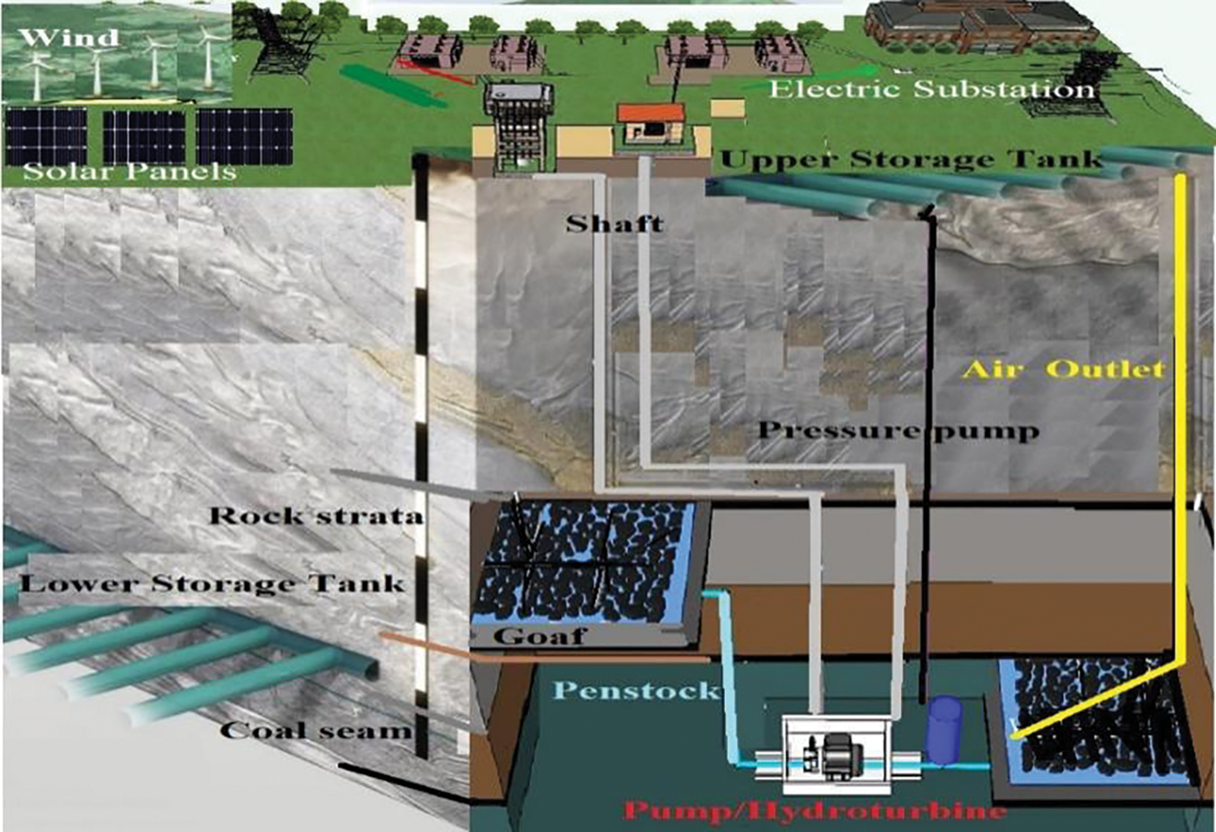
Figure 2: Hybrid hydro-pump system using abandoned coal mine
3 Equations and Mathematical Expressions
The projected system consists of wind generators, PV modules, reversible hydraulic pump turbine, penstocks, and 2-storage tanks. Wind generators and PV systems transform clean energy into electrical power for load consumption. Once power generation exceeds the amount of power consumed, the excess power will drive the pump to raise the water from the bottom storage to the top storage, thereby keeping potential energy. During the intermittent nature of the wind and solar power systems, when peak load demand cannot be met, water in the storage would be released to power the hydro pump turbine and complement the power demand by the loads.
Wind generators use a shaft power
where
The energy from the sun can be converted into electrical energy by a solar cell. Hence, power can be assessed by Eq. (3) [17], where:
The turbine’s input energy
The change in pressure
After coal mining, enormous rifts and porosities are capable of preserving water in the goaf region. Depending on the proximity to the pit as shown in Fig. 3, the overlying rock segments over the mined pit can be categorized into “different regions,” such as the caving, the fissure and the displacement region. The caving region is located somewhere higher than the residual coal, and significant rock segmentation has been attributed to the development of a huge storable area. There are numerous fissures and deformations over the caving region (fissure region) that can also hold some liquid.
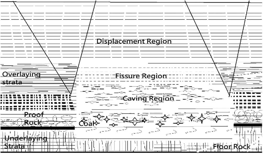
Figure 3: Strata regions
The rock in the displacement region only has a few micro-cracks and no storage capacity, but it has a higher porosity because of the presence of microcracks. The rock mass extension coefficient
Whenever there is a greater amount of power available from wind and solar systems during the peak load,
Aside from the system efficiency
When
5 Designed Indicators for the Hydro-Pump
It is assumed that the storage tanks are entirely narrow, meaning that perhaps the leak value is zero, the moisture interaction within the goaf is perfect, and the pressure drop is negligible. The differential in the head of the 2-storage tanks is 149.5 m. The original radius of penstocks is 1.5 m, and the reservoir capability of one goaf is momentarily specified at 1.039 × 10⁵ m3. The storage original water level is zero. The spacing of major roadways in coalfields is usually around 5 m. However, a larger pipe reduces wall tension and thus increases system performance, the diameter of the pipe must be less than 3.5 m to give access to check and repair the facilities. The value of the radius chosen for penstock in this article has been set at 1.5 m. Table 1 depicts the daily load profile for a specific day (15th September 2022) around Klipkop, Pretoria, South Africa. Table 2 summarizes the other preliminary concept variables and comprehensive requirements for simulation and evaluation.


6 The System Simulation and Discussion
Fig. 4 depicts the system’s simulation and water fluctuation in the overhead tank when the wind energy ratio
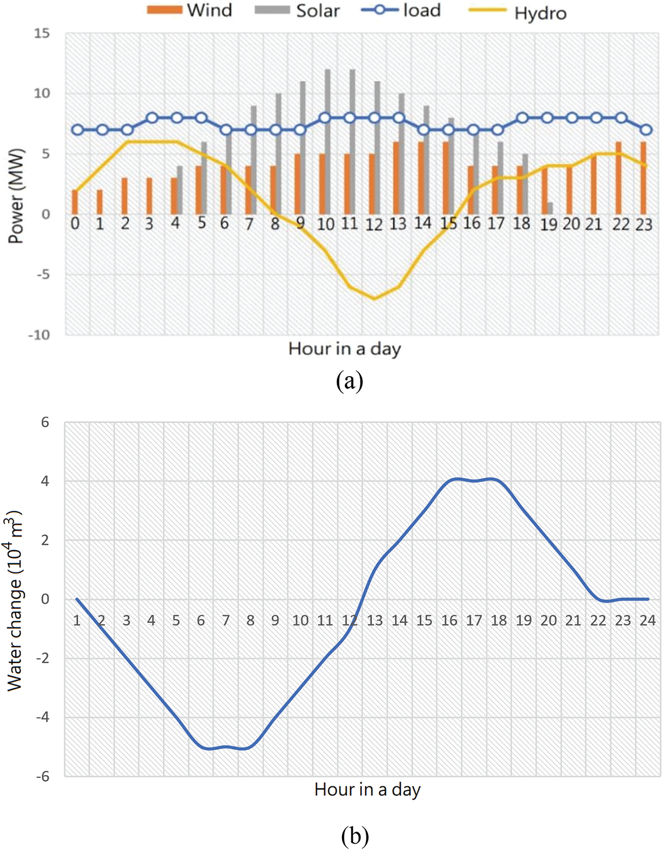
Figure 4: Output of the system (a) power in a day (b) water interaction in top storage in a day
A bigger storage capacity is obtained from having more goaves acting as reservoirs. Since the system performance is lowered when only one penstock is operating, due to increasing pressure loss as the water flow velocity rises. The system efficiency and average regulated load for varied goaf numbers are presented in Fig. 5a. The utilizable total storage of the goaf reservoirs increases from 8.29 × 10⁴ m3 to 116.78 × 10⁴ m3 when the goaf number increases from 1 to 17 while system efficiency is reduced to 80.3% from 82.9% as shown in Fig. 4a. This is due to the friction created on the penstock wall by increased water flow from 5 to 72 m3/s thus inducing higher pressure loss. Since the controlling energy density (Econt.) is dependent on the load profile and penstock height difference rather than the storage capacity, it remains stable at 1.585 kWh/m3 as depicted in Fig. 5b. System efficiency is a crucial metric for assessing power-generating effectiveness. The number of goaves or the reservoir capacity should be regulated because a minimum level of system efficiency must be ensured. As an illustration, if the minimum system efficiency is set at 80%, the reservoir’s maximum storage capacity would be
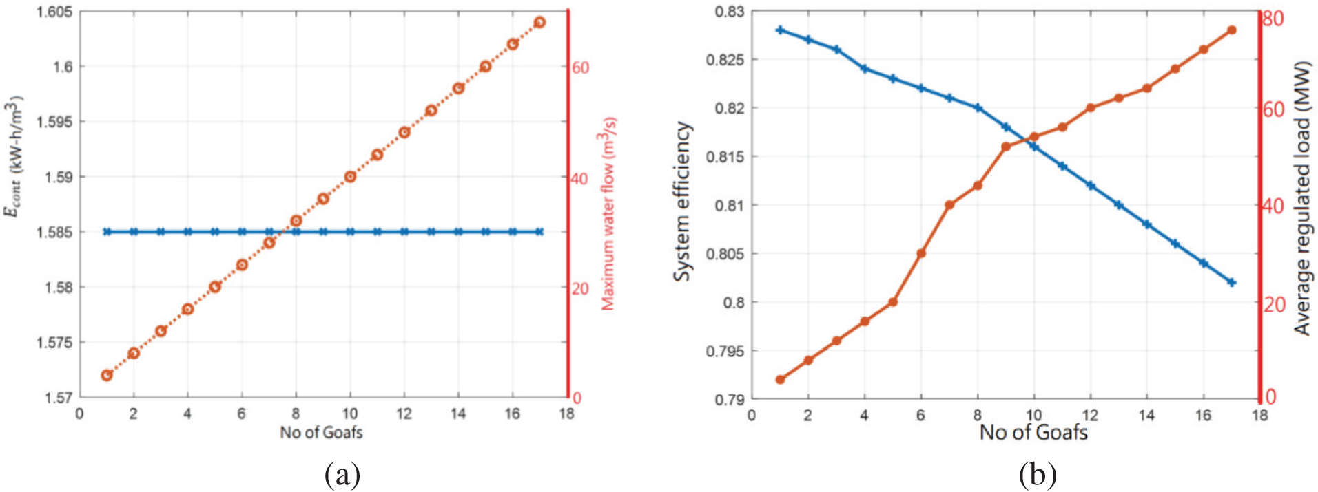
Figure 5: (a) System performance and average controlled load with various goaf numbers (b) controlling density with number of goafs
Fig. 4 depicts the overall system performance in a daily performance scenario. The pump’s peak input of
Table 3 presents the annual mean load demand, wind speed, and solar energy concentration in Klipkop from 2013 to 2021. Fig. 6a depicts the element output and water fluctuation over 12 months when the wind energy proportion is 0.5. The peak input of the pump at −11.10 kW occurred in February, and its peak output power of 11.1 kW in August as shown in Fig. 5a. The water level in the overhead storage tank rises gradually over time from September to July of the succeeding year, achieving a maximum of

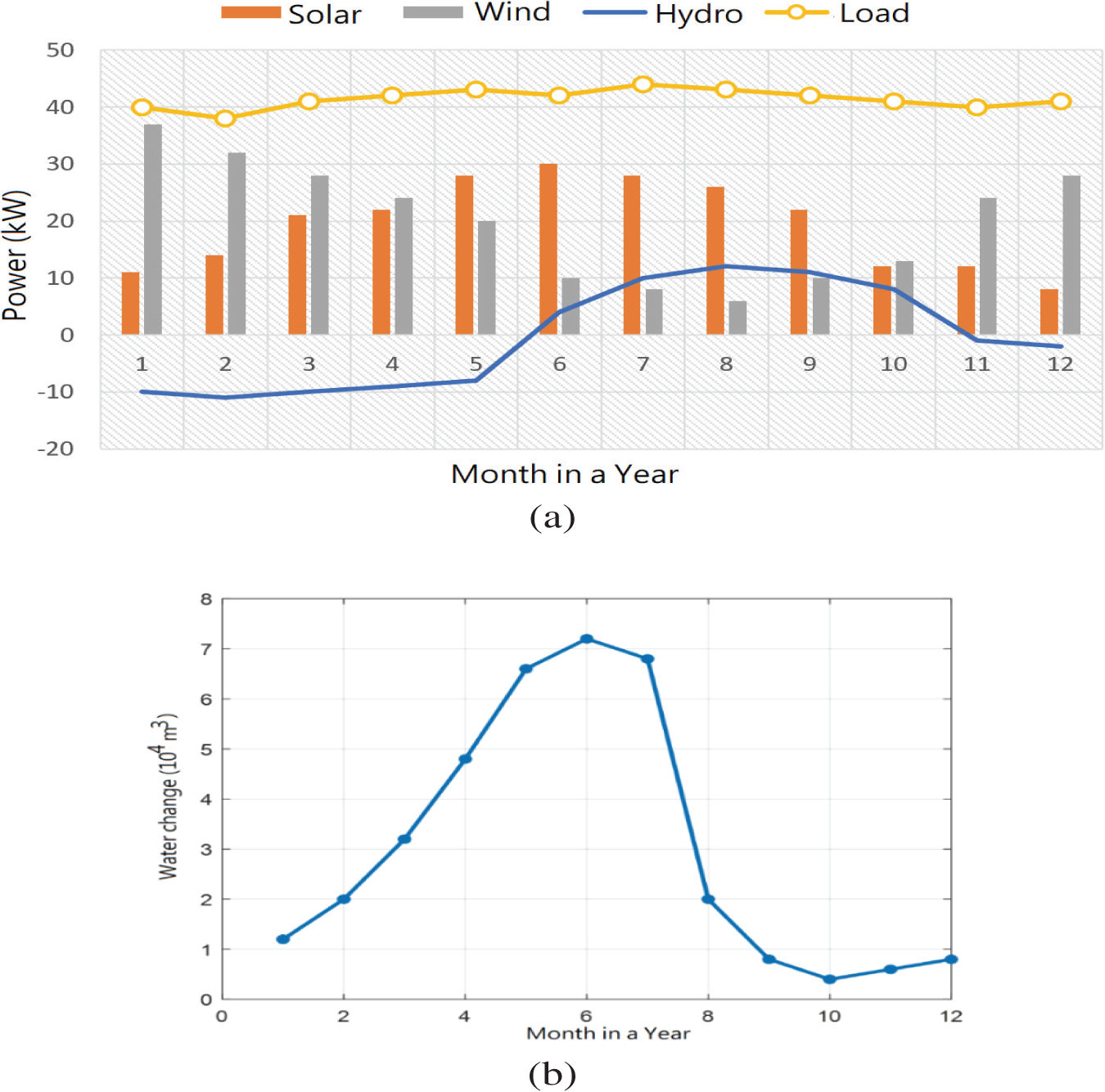
Figure 6: (a) Scenario output and (b) variation in water in a year at
6.4 Different Power Configurations
The performance of the model might vary depending on different power configurations. Fig. 7a depicts the operation of the daily operation regulation scenario, the conserved-absorbed ratio
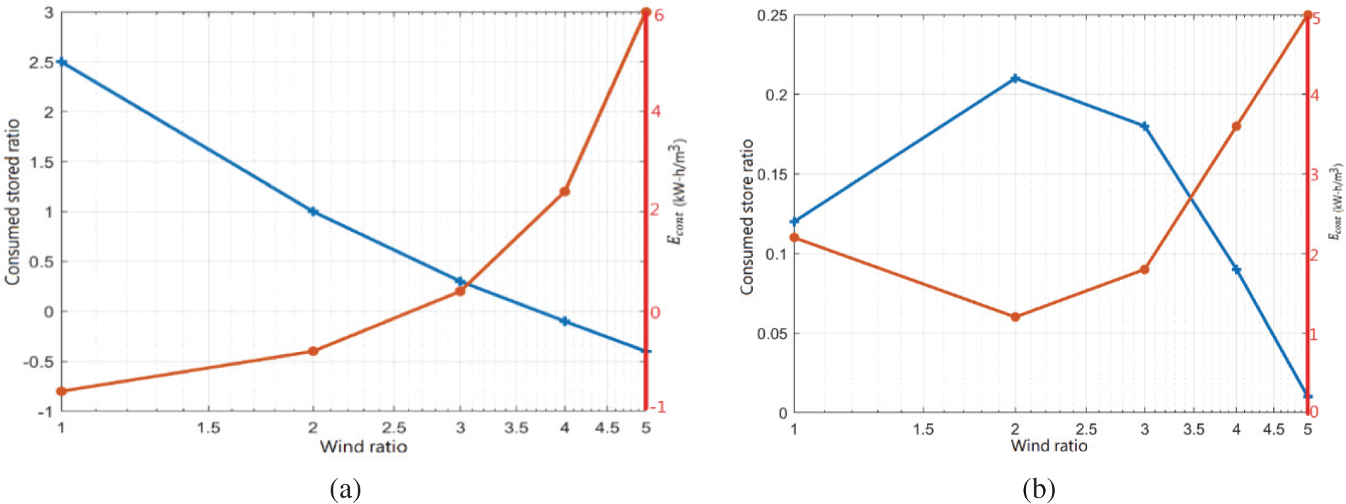
Figure 7: The conserved-absorbed ratio
6.5 Abandoned Coal Mine’s Viability Potential
This section discusses issues relating to the use of abandoned coal mines for pumped hydro-energy storage systems. The coal mine goaf’s capacity was determined, and its suitability as a pumped hydro-energy storage reservoir was examined in relation to the saturation line. Thereafter, the Finite Element Technique was then used to examine the water leakage from the reservoirs. Then, the ideal air circulation shaft size was calculated, and the exact horizontal air circulation tubes for air exchange were recommended. Apart from the lithology, the extraction level (or pressure) and the width of the coal mine can significantly affect the coefficient of expansion

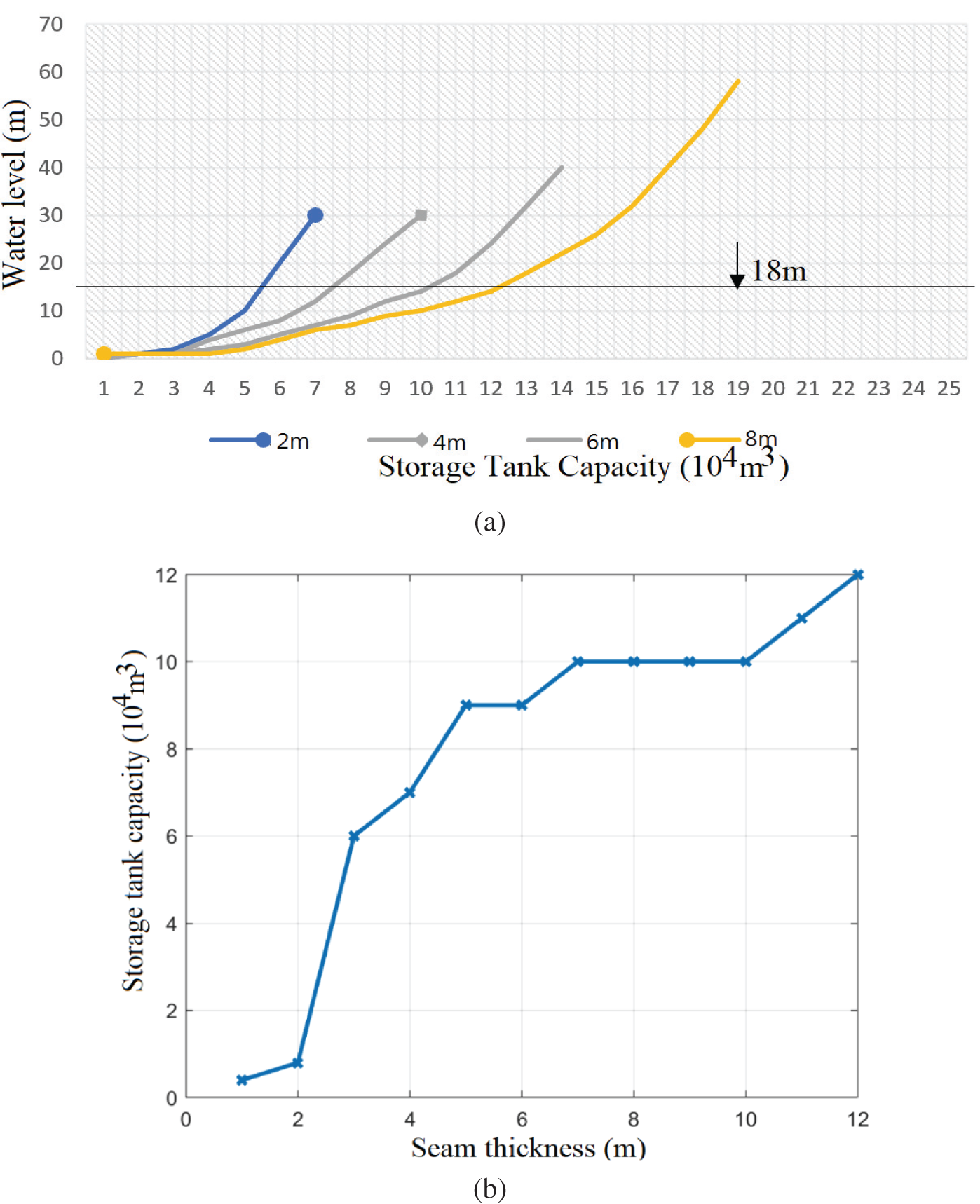
Figure 8: (a) The storage tank capability (b) the reservoir capability
The selection of a hybrid-HWS energy strategy would guarantee a reasonable percentage of yearly power consumption fulfillment. Fig. 9 depicts the power impacts of the hybrid-HWS renewables for regular summer and winter days scenario. Despite having a low generated solar energy (1/6 wind), it can be extremely beneficial on hot summer days, particularly at noon when the wind reduces and radiation from the sun rises. Nevertheless, while expanding PV total capability guarantees 65% of usage across wind power and solar system as shown in Figs. 9d and 9h hydro-pump supports the variation with the pump/hydropower strategy in Figs. 9b and 9f also meet active power demand while also preserving grid reliability by supplying or absorbing reactive power in a manner similar to that described in [17]. Most winter days have excess wind production early in the day, which can be used to lower the cost of power for scheduled pumping in the morning. Moreover, when compared to other situations, there is virtually no major contribution to the storage capability of 144 and 288 MWh in Figs. 9c and 9g. It is critical to confirm sometime around 12:00–23:00, the generator capacity in all situations in Fig. 9d that the generator volume is less than the lowest generator volume accepted; thus, the system will not function through such hours, even with higher Photovoltaic production. Because the system relies not on the surplus wind and solar power, the scenario in Figs. 9a and 9e demonstrates a more efficient use of hydropower. Nonetheless, thinking about the fact that this control remedy must be linked to the power network because the system will not be often energized by wind and solar power to operate pumping. Considering that the maximum power is 3.99 MW, with each daily consumption of
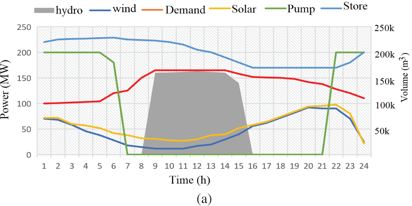
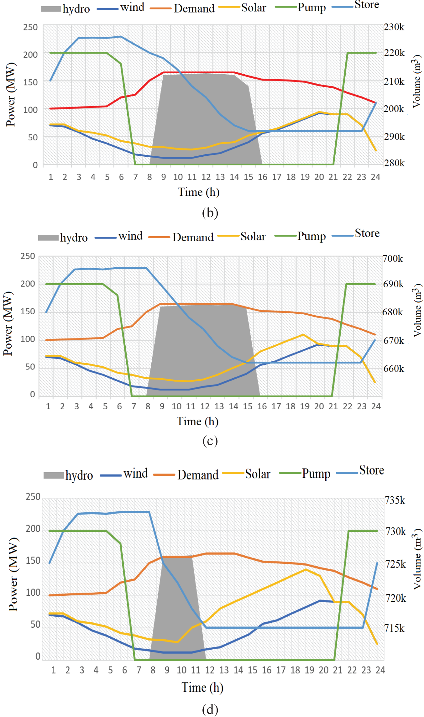

Figure 9: (a–d) The power contribution in the summer scenario, (e–h) are the power contribution in the winter scenario
Fig. 10a depicts the involvement of each electricity generation to demand fulfillment for four situations. It is obvious that storage qualities (for both wind and pump-hydro) have a significant impact on utilization fulfillment. This is less noticeable when solar and pump-hydro are combined, particularly at greater storage qualities. Wind power is more efficient for every situation because there is a small difference between the peak and lowest generation qualities. In the first case, as shown in Fig. 10b, the pump-hydro involvement is higher than in other circumstances, resulting in more unfulfilled demand and lower wind and solar power influence. In the second situation, improving wind/solar energy improves fulfilled utilization from the power input by close to 3.9% over the preceding one. Nonetheless, a pump-hydro projects storage system with double the nominal capacity provides no benefit in Fig. 10c. However, when compared to the fourth situation in Fig. 10d, improving the generated solar sometimes does not make a significant contribution to the network stability or consumer fulfilment. As a result, expanding the pump-hydro system, which can retain water reserves, is not beneficial to assisting utilization because it is fully extended for aligning power sources to peak demand durations as shown in Fig. 10c. As a result, the first and the second situations showcase the main focus of renewable power. Several of the difficulties related to sustainable energy sources might be overcome if a portion of the excess power generated by renewable sources during non-peak hours (i.e., photovoltaics in the summer) might be saved and released when consumption increases. Nevertheless, when making comparisons between the second and the first situation in Fig. 10b, this workaround seems to be more costly, necessitating assessment charges for the suitability of this system.
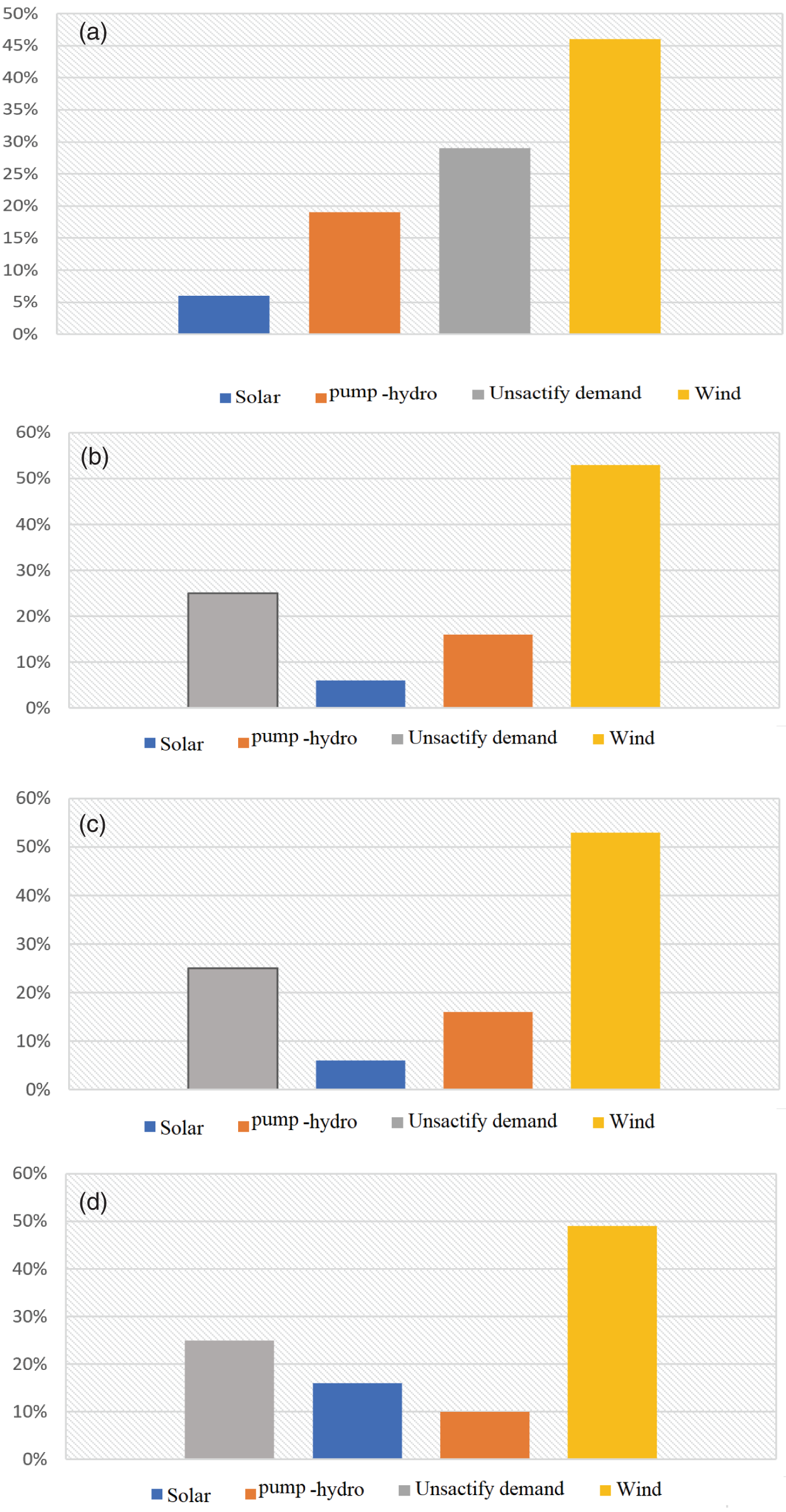
Figure 10: Contribution of each electricity generation to demand fulfilment for four situations
This study demonstrated that a hydro-pump system incorporating other renewable sources is an interesting sustainable option. Because of the consistency of hydro by pumping and the stochastic fluctuation of other renewable resources and electricity consumption, the energetic involvement of various sources reveals unique characteristics. The hybrid-HWS system such that by integrating the three systems in a harmonizing and consistent manner, might produce and store power at a cheap price, combating climate change and lowering the power generation in a self-satisfactory approach. Hence, a sustained guideline was created to maximize renewable energy accessibility and conservation, choosing the optimal mixture of maximum variables to produce the most efficient remedy in terms of performance, power use, prices, and footprint. The major deduction from the study is that substituting fossil fuels with clean energy systems necessitates extensively disseminating deployments such as wind generators; employing a variety of various intermittent power distributions, particularly ones that are partly supplementary (e.g., hot climate frequently implies low winds and conversely); and corresponding with the appropriate operation of power sources during peak demand periods. This work demonstrates that the pumped hydro energy storage system is technically capable of integrating other renewable energy sources (Wind and Solar) as a cost-effective energy solution. It was observed in the scenarios that one of the more significant hurdles for sufficient energy generation is this cutout wind speed, as much potential energy is lost due to the limitation of these turbines. At the same time, a hybrid WindSolar-PHES system would need an energy storage capacity of at least 10–15 h to cover the shortfall in electricity demand during periods of low wind or solar power production. which necessitates a large volume of the upper reservoir.
Nonetheless, there has been ample proof that each of these modern integrated methods for synergies among clean energy sources can decrease electricity tariffs and improve overall power quality, which are the primary goals of the hybrid-HWS approach. The excess power from hydropower generated during periods of low consumption such as solar energy in the summer period can be preserved and released when consumption increases.
Acknowledgement: The authors acknowledge the support of the DUT Smart Grid Research Centre.
Funding Statement: This study was supported by the DUT Scholarship Scheme Masters: 2022 (RFA Smart Grid) Funding.
Author Contributions: The authors confirm their contribution to the paper as follows: The study conception and design: Uwem O. Ikitde, Abayomi A. Adebiyi, Innocent E. Davidson and Ayodeji S. Akinyemi. Data collection: Uwem O. Ikitde, Abayomi A. Adebiyi, and Ayodeji S. Akinyemi. Analysis and interpretation of results: Innocent E. Davidson and Ayodeji S. Akinyemi. Draft manuscript preparation: Abayomi A. Adebiyi and Ayodeji S. Akinyemi. All authors reviewed the results and approved the final version of the manuscript.
Availability of Data and Materials: Data supporting this study are included within the article.
Conflicts of Interest: The authors declare that they have no conflicts of interest to report regarding the present study.
References
1. Tang, Z., Y-ang, Y., Blaabjerg, F. (2022). Power electronics: The enabling technology for renewable energy integration. Journal of Power and Energy Systems, 8(1), 39–52. https://doi.org/10.17775/CSEEJPES.2021.02850 [Google Scholar] [CrossRef]
2. Abubakr, H., Vasquez, J. C., Mahmoud, K., Darwish, M. M. F., Guerrero, J. M. (2022). Comprehensive review on renewable energy sources in Egypt—Current status, grid codes and future vision. IEEE Access, 10, 2169–2196. https://doi.org/10.1109/ACCESS.2022.3140385 [Google Scholar] [CrossRef]
3. Ren, P. J., Hao, Z. N., Wang, X. X., Zeng, X. J., Xu, Z. S. (2022). Decision-making models based on incomplete hesitant fuzzy linguistic preference relation with application to site selection of hydropower stations. IEEE Transactions on Engineering Management, 69(4), 904–915. https://doi.org/10.1109/TEM.2019.2962180 [Google Scholar] [CrossRef]
4. Fu, H., Tong, X., Pan, Z., Liu, F., Wang, F. et al. (2022). Research on BESS participating in power system primary frequency regulation control strategy considering state-of-charge recovery. Proceeding of International Conference on Energy, Electrical and Power Engineering (CEEPE), pp. 1–6. Chongqing, China. https://doi.org/10.1109/CEEPE55110.2022.9783400 [Google Scholar] [CrossRef]
5. Zhang, S., Xiang, Y., Liu, J., Liu, J., Yang, J. et al. (2022). A regulating capacity determination method for pumped storage hydropower to restrain PV generation fluctuations. Journal of Power and Energy Systems, 8(1), 304–316. https://doi.org/10.17775/CSEEJPES.2020.01930 [Google Scholar] [CrossRef]
6. Huang, B., Chen, Y., Baldick, R. (2021). A configuration based pumped storage hydro model in the MISO day-ahead market. IEEE Transactions on Power Systems, 37(1), 132–141. https://doi.org/10.1109/TPWRS.2021.3097270 [Google Scholar] [CrossRef]
7. Kim, W. J., Lee, Y. S., Chun, Y. H., Jeong, H. S. (2022). Reserve-constrained unit commitment considering adjustable-speed pumped-storage hydropower and its economic effect in Korean power system. Energies, 15(7), 1–23. https://doi.org/10.3390/en15072386 [Google Scholar] [CrossRef]
8. Shirinda, K., Kusakana, K., Koko, S. P. (2020). Optimal power dispatch of a grid-connected photovoltaic with groundwater pumped-hydro storage system supplying a farmhouse. Proceeding of International Conference on Smart Grid and Clean Energy Technologies, pp. 1–6. Kuching, Malaysia. https://doi.org/10.1109/ICSGCE49177.2020.9275604 [Google Scholar] [CrossRef]
9. Braat, K. B., van Lohuizen, H. S., de Haan, J. F. (1985). Underground pumped hydro-storage project for the Netherlands. Tunnels Tunneling, 17(11), 19–22. https://doi.org/10.1016/0148-9062(86)90918-6 [Google Scholar] [CrossRef]
10. Wong, I. H. (1996). An underground pumped storage scheme in the Bukit Timah Granite of Singapore. Tunnelling and Underground Space Technology, 11(14), 485–489. https://doi.org/10.1016/S0886-7798(96)00035-1 [Google Scholar] [CrossRef]
11. Severson, M. J. (2011). Preliminary evaluation of establishing an underground taconite mine, to be used later as a lower reservoir in a pumped hydro energy storage facility, on the Mesabi Iron Range, Minnesota, vol. 2011, pp. 1–37. Duluth: University of Minnesota Duluth. https://hdl.handle.net/11299/187087 [Google Scholar]
12. Fan, J., Xie, H., Chen, J., Jiang, D., Li, C. et al. (2020). Preliminary feasibility analysis of a hybrid pumped-hydro energy storage system using abandoned coal mine goafs. Applied Energy, 258, 1–13. https://doi.org/10.1016/j.apenergy.2019.114007 [Google Scholar] [CrossRef]
13. Pickard, W. F. (2011). The history, present state, and future prospects of underground pumped hydro for massive energy storage. Proceedings of the IEEE, 100(2), 473–483. https://doi.org/10.1109/JPROC.2011.2126030 [Google Scholar] [CrossRef]
14. Liu, W., Zhang, Z., Chen, J., Fan, J., Jiang, D. et al. (2019). Physical simulation of construction and control of two butted-well horizontal cavern energy storage using large molded rock salt specimens. Energy, 185, 682–694. https://doi.org/10.1016/j.energy.2019.07.014 [Google Scholar] [CrossRef]
15. Menéndez, J., Loredo, J., Galdo, M., Fernández-Oro, J. M. (2019). Energy storage in underground coal mines in NW Spain: Assessment of an underground lower water reservoir and preliminary energy balance. Renewable Energy, 134, 1381–1391. https://doi.org/10.1016/j.renene.2018.09.042 [Google Scholar] [CrossRef]
16. Smail H., Alkama R., Medjdoub A. (2018). Impact of large scale power plant connection on congestion in the algerian electricity transmission system. Energy, 159, 115–120. https://doi.org/10.1016/j.energy.2018.06.076 [Google Scholar] [CrossRef]
17. Fan, J., Chen, J., Jiang, D., Wu, J., Shu, C. et al. (2019). A stress model reflecting the effect of the friction angle on rockbursts in coal mines. Geomechanics and Engineering, 18, 21–27. https://doi.org/10.12989/gae.2019.18.1.021 [Google Scholar] [CrossRef]
18. Zhang, T., Zhou, J., Zhang, Y., Liu, Y., Li, Y. (2022). Synergetic control strategy for water hammer wave and mass wave in hydropower station with downstream channel. IEEE Access, 10, 81105–81122. https://doi.org/10.1109/ACCESS.2022.3195172 [Google Scholar] [CrossRef]
19. Tiwari, R., Chelliah, T. R. (2022). Design improvement and tuning of excitation system ST5B with PSS3B and coordinated OEL in hydropower plant. IEEE Transactions on Industry Applications, 55(5), 5895–5907. https://doi.org/10.1109/TIA.2022.3184667 [Google Scholar] [CrossRef]
Cite This Article
 Copyright © 2023 The Author(s). Published by Tech Science Press.
This work is licensed under a Creative Commons Attribution 4.0 International License , which permits unrestricted use, distribution, and reproduction in any medium, provided the original work is properly cited.
 Downloads
 Citation Tools