
 Submit a Paper
 Propose a Special lssue
 Open Access
ARTICLE

Fault Monitoring Strategy for PV System Based on I-V Feature Library
1 School of Electrical and Information Engineering, Tianjin University, Tianjin, 300000, China
2 State Grid Shuozhou Electric Power Supply Company, Shuozhou, 036000, China
3 China Huaneng Clean Energy Research lnstitute Technology Co., Ltd., Beijing, 102209, China
* Corresponding Author: Yanbo Che. Email:
Energy Engineering 2024, 121(3), 643-660. https://doi.org/10.32604/ee.2023.045204
Received 20 August 2023; Accepted 02 November 2023; Issue published 27 February 2024
 View Full Text
 Download PDF
Abstract
Long-term use in challenging natural conditions is possible for photovoltaic modules, which are extremely prone to failure. Failure to diagnose and address faults in Photovoltaic (PV) power systems in a timely manner can cause permanent damage to PV modules and, in more serious cases, fires. Therefore, research into photovoltaic module defect detection techniques is crucial for the growth of the photovoltaic sector as well as for maintaining national economic prosperity and ensuring public safety. Considering the drawbacks of the current real-time and historical data-based methods for monitoring distributed PV systems, this paper proposes a method for monitoring PV systems at the module or string level that can be achieved by monitoring only electrical signals. The approach doesn’t need a lot of tests to get the operational data of PV modules beforehand and only requires theoretical feature libraries of PV modules through panel parameter calculations. The present operating conditions and the open-circuit and short-circuit faults can be precisely identified by comparing the observed open-circuit voltage and short-circuit current with the corresponding data in the theoretical feature library. After that, by comparing the measured maximum power point voltage and current with the corresponding data in the theoretical feature library through the threshold method, aging and shadowing faults can be accurately determined. Experimental testing was done to see whether the suggested method was effective. The results show that the proposed technique is able to diagnose open-circuit faults, short-circuit faults, aging faults, and shadowing faults with shadow occlusion above 20%.Keywords
In order to prevent yield losses and extend the amortization period of solar systems with high initial installation costs, fault-free operation of photovoltaic systems is crucial [1]. Distributed PV has developed rapidly in recent years, and has become the main force of the current world’s new installed PV capacity. In China, for example, according to the National Energy Administration, the installed capacity of distributed PV reached 108 million kilowatts in 2021, accounting for about one-third of all installed PV capacity on the grid. Distributed PV added about 29.279 million kilowatts, accounting for about 55% of all new installed PV power generation and breaking 50% for the very first time in history.
Long-term use in hostile conditions makes photovoltaic modules more prone to failure. Failure to identify and fix problems with PV power systems in a timely way can result in fires and irreversible damage to PV modules. Therefore, research into solar module defect detection techniques is crucial for the growth of the photovoltaic sector as well as for maintaining national economic prosperity and ensuring public safety.
To correctly identify the errors that arise in PV systems, many monitoring and troubleshooting methods have been studied in the literature, which vary in terms of speed, complexity, and sensor requirements, as well as the ability to identify a large number of faults [2,3]. There are three types of PV defect detection techniques: optical, thermal, and electrical [4]. Fault detection based on optical and thermal methods is expensive in terms of equipment, which limits the versatility of this method. The electrical approach has become the most widely applied fault monitoring method due to its low equipment cost and easy data acquisition. Electrical methods analyze the operating conditions by monitoring the electrical parameters of the PV system, which are mainly divided into two methods based on historical data and real-time data.
Methods based on historical data include statistical analysis and artificial intelligence algorithm monitoring methods. The statistical analysis method sets reasonable fault alarm trigger thresholds by analyzing historical data. Artificial intelligence algorithms have also been widely used for troubleshooting. Indeed, artificial intelligence algorithms have been widely applied to analyze the current operating conditions through historical data. For example, in references [5,6], the extreme learning machine algorithm was used, and different neural network algorithms were employed in references [7,8]. These methods leverage the power of artificial intelligence to accurately predict and analyze the performance of photovoltaic systems in real-time. The method based on historical data is widely used in large-scale photovoltaic power plants that have comprehensive historical data records. However, with the rapid development of distributed photovoltaic systems, there are significant differences in installed capacity and a wide variety of component models and interconnection methods. Thus, it is difficult to obtain complete historical data for various distributed photovoltaic systems, making it challenging to predict the operational status of the systems.
To address the limitations of the historical data-based methods, scholars have developed an approach based on real-time data. The real-time data-based approach generally determines the presence of faults by monitoring the differences between the electrical parameters of operating PV modules, strings, and arrays and the simulation results. In references [9–11], the photovoltaic module power generation was primarily predicted using environmental parameters and photovoltaic array parameters. A comparison is then made with the real-time system power generation to enable monitoring of the photovoltaic system. Reference [12] monitored large photovoltaic power plants in Thailand by monitoring the GT value of photovoltaic systems. The monitoring system mentioned above requires continuous monitoring of various parameters and real-time computations, which can be costly. Therefore, some scholars have proposed fault monitoring methods that only require analyzing the operating condition of photovoltaic systems based on fixed-time measurements. In reference [13], an online fault monitoring method was proposed which monitors open, short, and partial faults by operating voltage and ambient temperature. Reference [14] built upon the foundation of reference [13] by incorporating irradiance monitoring. In references [15,16], on the other hand, introduced current monitoring by utilizing four characteristic parameters: temperature, irradiance, current, and voltage. This expanded monitoring approach allows the detection of four types of faults: open-circuit faults, short-circuit faults, shading faults, and aging faults. While increasing the monitoring of environmental parameters can enhance monitoring accuracy, it also simultaneously increases monitoring costs and inherent errors. Environmental sensors can only monitor environmental values and cannot accurately acquire the temperature and irradiance on the PV modules, thus introducing errors. In addition, for small and widely distributed PV systems, it is even more difficult to ensure monitoring accuracy with only a small number of environmental sensors. Therefore, in reference [17], a monitoring method was proposed that does not require monitoring irradiance but can still detect four typical faults. Although the improvements were made in reference [17], it still utilizes temperature as an environmental variable. It is challenging to accurately obtain the actual temperatures of each component in distributed photovoltaic systems operating under highly complex conditions. Since electrical parameters such as current and voltage are directly obtained from the photovoltaic modules with high precision, proposing a monitoring method that eliminates the need for environmental variables and only requires electrical variables could significantly enhance monitoring accuracy and reduce monitoring system costs.
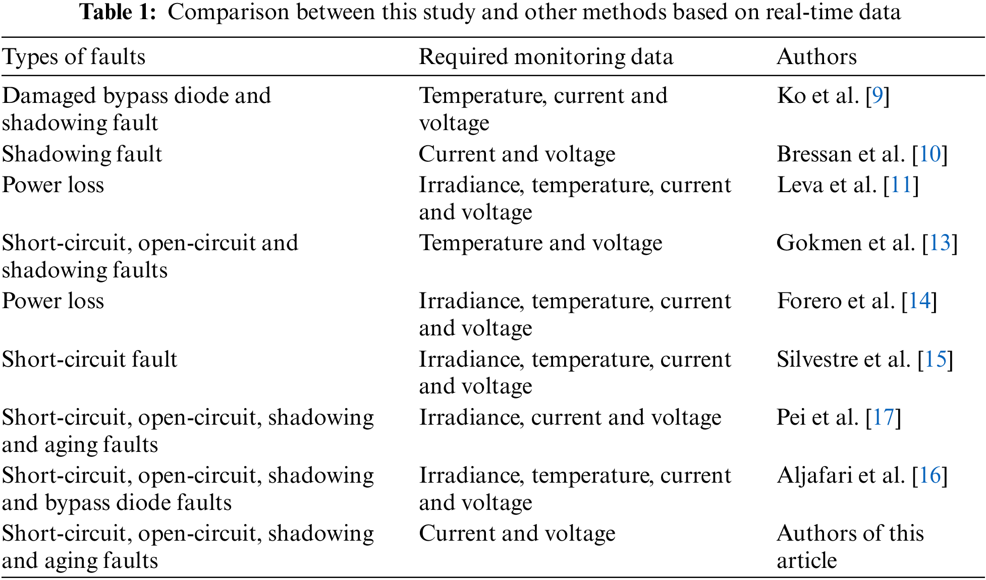
Considering the limitations of various monitoring methods currently applied to distributed photovoltaic systems, this paper proposes a novel real-time data-based monitoring method. This approach enables the monitoring of module or string-level photovoltaic systems solely through the analysis of electrical signals. In contrast to other methods, this approach only requires monitoring the open-circuit voltage, short-circuit current, and voltage and current at the maximum power point, without the need for environmental parameter monitoring. A comparison between this study and other methods based on real-time data is shown in Table 1.
The PV module output characteristics are mainly related to the working conditions (temperature, irradiance). The I-V curves of PV modules under different working conditions are shown in Fig. 1. There are four characteristics of the output characteristics: open circuit voltage
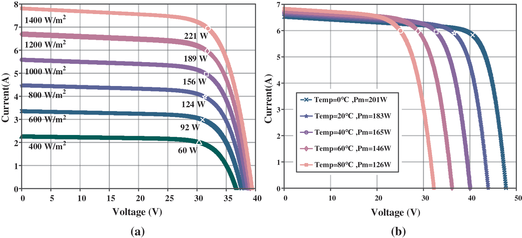
Figure 1: I-V curve under various operating circumstances: (a) I-V curves at different irradiances; (b) I-V curves at different temperatures
The main types of PV module failures are short circuit, open circuit, partial shading, and degradation faults. Open-circuit faults are caused by disconnected cell connections and physical damage, etc., manifested as
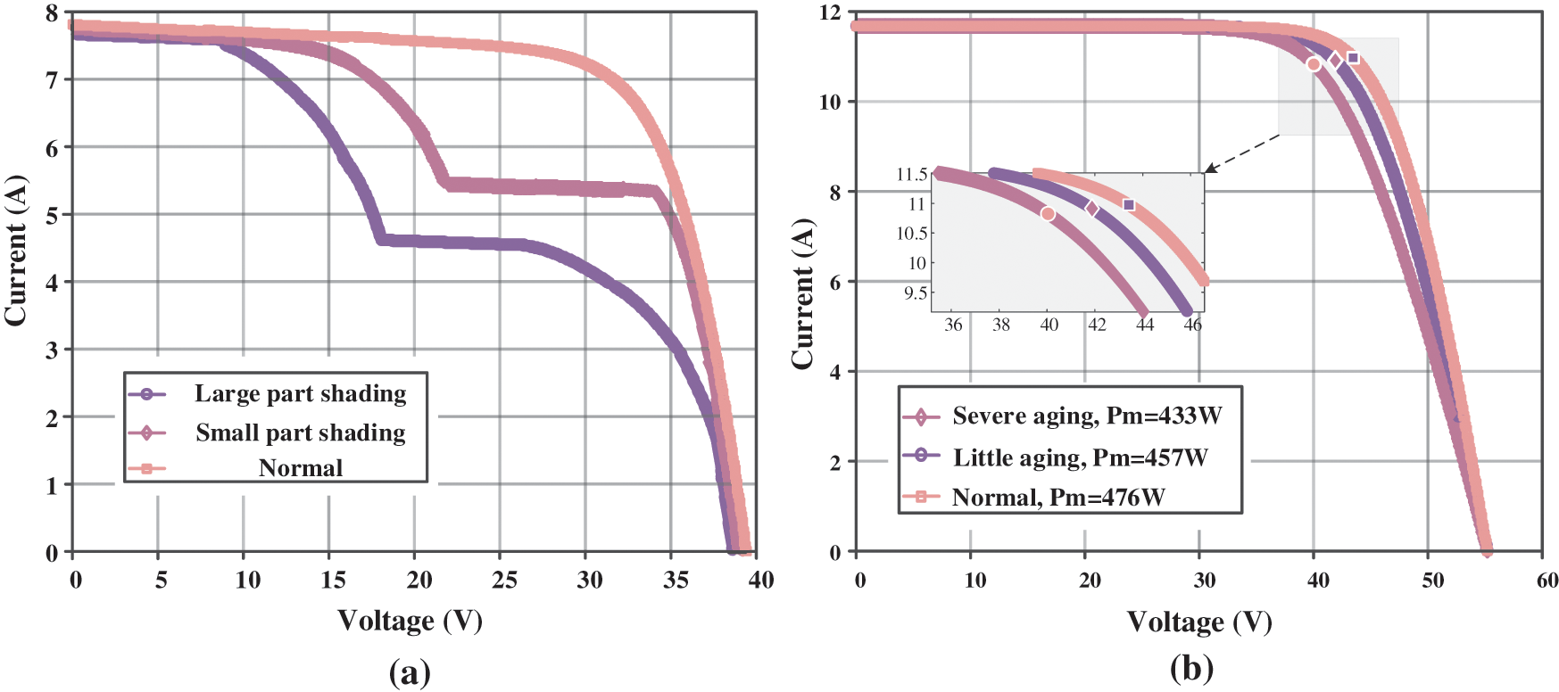
Figure 2: I-V curves under different faults: (a) partial shadowing faults; (b) degradation faults
For the above faults, open circuit faults can be accurately determined by whether
However, according to Fig. 1, there may be equal correspondence between
Irradiance and temperature relationships, as well as those between
where,
Since
When
In reference [21], the thermal coefficient of the
In summary, there are no two different sets of temperatures and irradiances that make
According to Chapter 2, the specific implementation process of the fault monitoring method is:
(1) To obtain
(2) Monitor open-circuit, short-circuit, aging, and shadow-obscuring faults online through the theoretical feature library and fault features.
3.1 Theoretical Feature Library Solving
The panel parameters of PV modules are generally
where
Under different working conditions, series resistance remains essentially the same. The photocurrent and diode saturation current are given by:
where
where
where
where
According to reference [23], using the factory parameters of the PV module, the five parameters
where
Let
Similarly, the PV module output power is expressed by output current and output voltage, respectively, as:
Derive Eqs. (19) and (20), respectively, and make the derivative equal to 0.
According to the method described in this section, the feature arrays of PV cells at different temperatures and irradiances are obtained to form a theoretical feature library.
This study only takes into consideration scenarios where the photovoltaic modules within the string have the same model and have been in use for the same duration. Due to the fact that the aging of photovoltaic modules is mainly related to humidity and altitude, only the entire string is considered to undergo the same degree of aging [24]. For shadowing faults, there may be situations where some modules experience shadowing or all modules experience shadow blocking. The likelihood of the occurrence of faults in which all modules within a string experience failure due to the open circuit or short circuit is extremely low. Therefore, the consideration is solely focused on scenarios where only a fraction of components experience open circuit or short circuit faults. In conclusion, there are five types of faults at the string level: shadowing faults of partial modules; Shadowing faults of all modules; Aging faults of all modules; Short circuit faults of partial modules; and Open circuit faults of partial modules.
When a short circuit fault occurs in partial modules, the open circuit voltage of those modules is 0. When an open circuit fault occurs in partial modules, the short circuit current of the entire string is 0.
According to Section 2, the open-circuit and short-circuit fault characteristics are more obvious, so the presence of these two faults is first accurately determined. Considering the error of the measuring instrument and the minimum values of
The short-circuit fault monitoring threshold for
If the measured
When a shadowing fault of partial modules occurs, at the maximum power point, due to the photovoltaic modules being connected in series, the current through each module is equal at this time. The maximum power point voltage of the shaded module will be lower than that of the other modules. By monitoring the
After excluding the short circuit fault of partial modules, open circuit fault of partial modules, and shadowing faults of partial modules, The open circuit voltage and short circuit current of each photovoltaic module in the photovoltaic string are equal. Through Section 2, it can be proven that the operating conditions of each module of the photovoltaic string are the same at this time, so analysis can be conducted on the data of a single module. On the basis of the obtained theoretical feature library, the data pairs consisting of open-circuit voltage and short-circuit current from the actual measured data are compared with the theoretical feature library to determine the feature array with the smallest deviation. The operating conditions, i.e., temperature and irradiance, under which this array is located are closest to the current operating conditions. Under normal operating conditions, the measured
According to IEC61724, the error values for current, voltage, and power during measurement are 1% and 2%, respectively. Definition:
where
After determining the characteristic array, it is necessary to distinguish between the occurrence of aging or shadowing faults and normal operation by maximum power point current and voltage. Definition:
where
where
Since the power loss due to aging faults is small and often accumulative, while the power loss due to shadowing faults is closely related to the area of shading, the two faults can be distinguished by the range of shading. In this study, the monitoring threshold of shadow shading fault is set at 20% of the shading range. Setting:
If
In summary, the process of online fault monitoring is shown in Fig. 3.
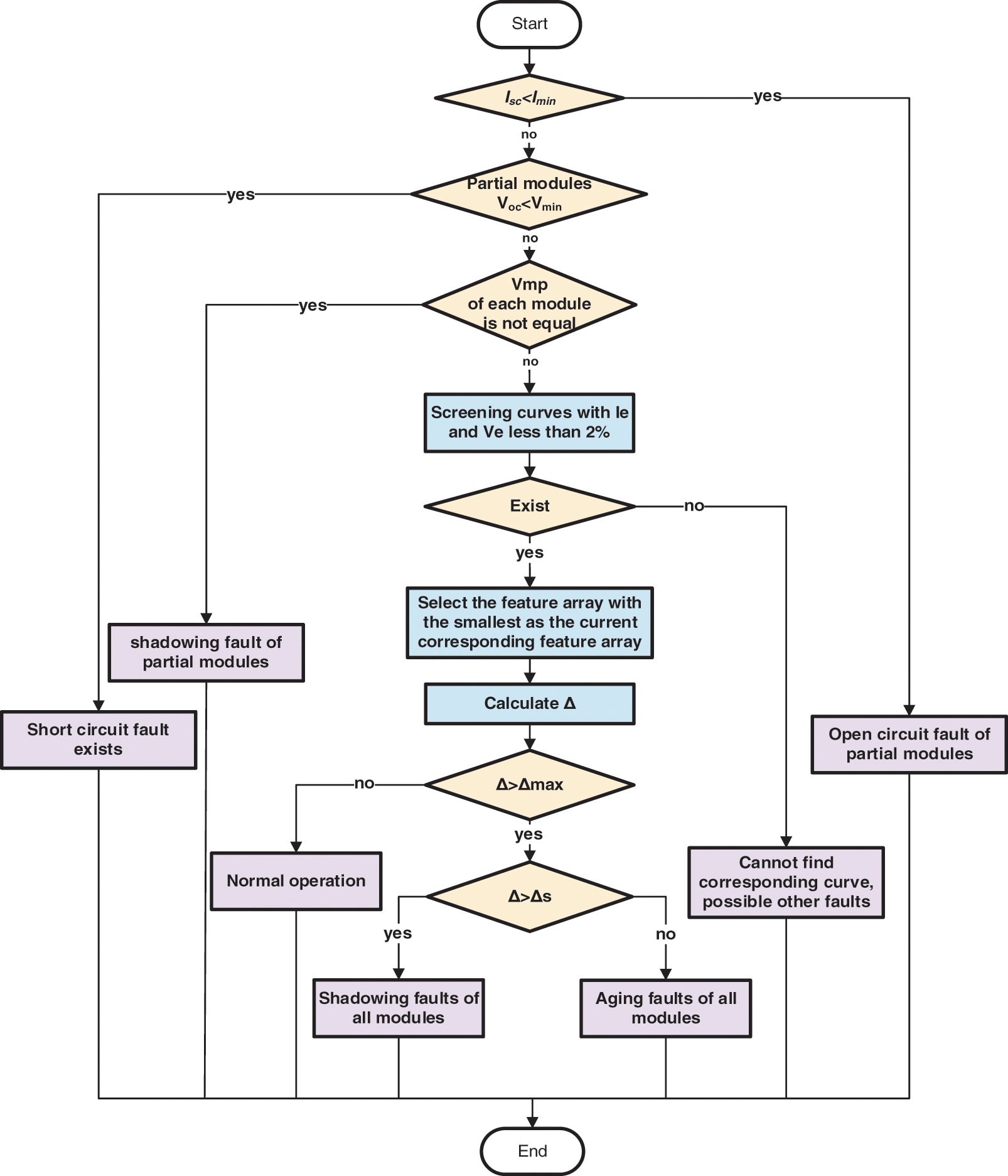
Figure 3: Online fault monitoring process
3.3 Monitor System and Experimental Setup
The detection system consists of a photovoltaic system, current and voltage monitoring equipment, controller, signal transmission system, and upper computer. The monitoring of open circuit voltage and short circuit current is carried out by installing voltage monitors at both ends of the photovoltaic module and current monitors at the string end. When conducting fault monitoring, the maximum power point voltage and current under operating status are first transmitted to the upper computer. Then, the system control module controls the string open circuit and transmits the corresponding open circuit voltage of each component to the upper computer. Then, the system control module controls the component short circuit and transmits the corresponding short circuit current of each component to the upper computer. Afterwards, the upper computer analyzes the input data through monitoring algorithms to determine the operational status of the photovoltaic string. The system schematic diagram is shown in Fig. 4.
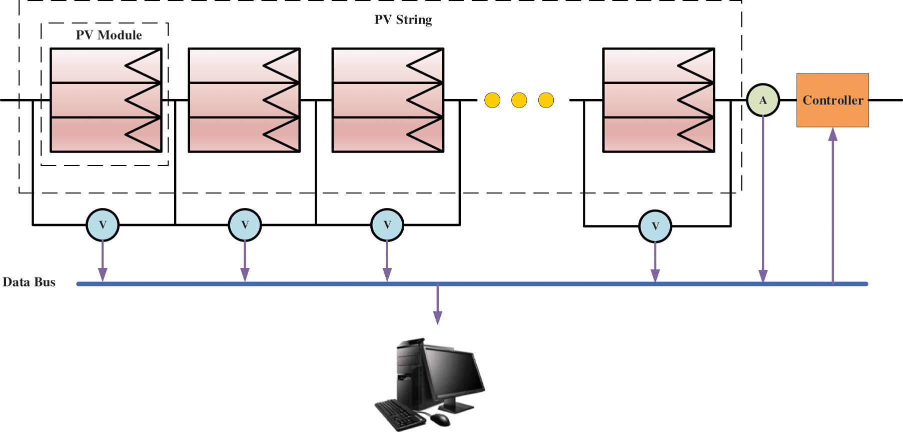
Figure 4: Monitor system
The experimental setup used in this study is shown in Fig. 5. The module can monitor the system current and voltage in real time. When the system is stabilizing the output, the module can be used to output
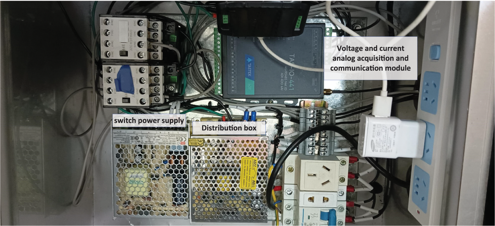
Figure 5: Experimental setup
The experimental setup was used to monitor the characteristic parameters of the PV modules under four types of faults and under fault-free operation, respectively. In the absence of constant temperature and irradiance equipment, the monitoring was carried out at 8:00 and 14:00 every day in January and June, respectively, in order to cover a large temperature and irradiance range.
4.1 Calculation Results of Theoretical Feature Library
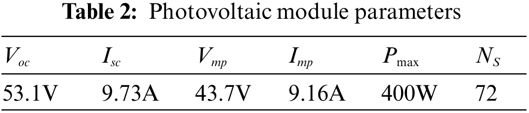
The PV module used is M81-400WT and the panel parameters are shown in Table 2.
Since
According to the method described in 3.1, 2499 sets of feature arrays were obtained to form the theoretical feature library, which is shown in Fig. 6.
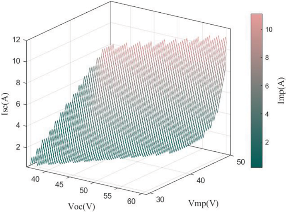
Figure 6: Theoretical feature library
For a given photovoltaic string, under the conditions of using identical photovoltaic modules, the electrical parameters will be the same under normal operation in the same environment. Therefore, an analysis can be conducted using the electrical parameters of a given module.
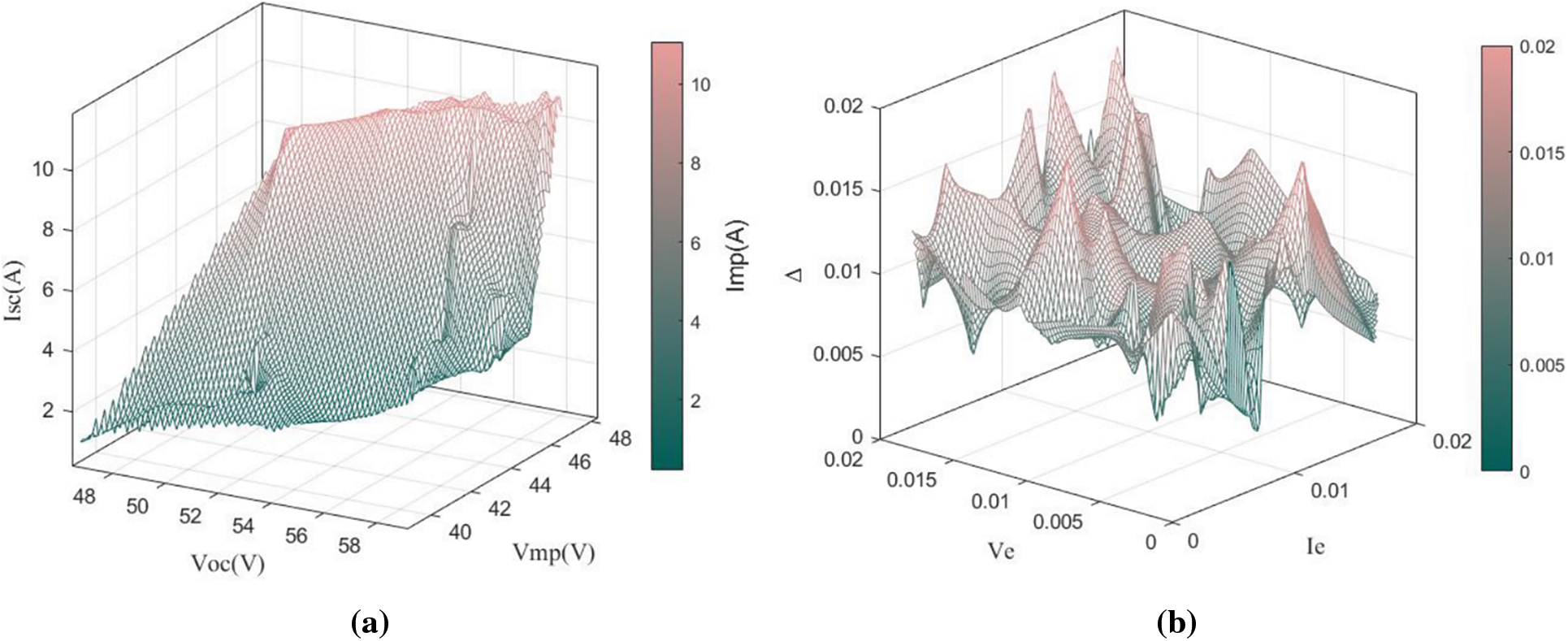
Figure 7: Results of experiments in fault-free operation: (a)
In all experiments,
4.3 Short-Circuit Fault and Open-Circuit Faults Experiments
As stated in chapter 2, when an open-circuit fault of partial modules occurs, the short-circuit current of the entire string drops to 0. When a short-circuit fault of partial modules occurs, the open-circuit voltage of that module is 0 and the open-circuit voltage of the other components is normal. In the experiment, three PV modules were connected in series and the first PV module was shorted and disconnected respectively. Taking a certain day as an example, the corresponding experimental data of the first PV module are shown in Table 3.
When the open-circuit fault occurs,
Since each module of the PV string is located in the same ambient humidity and altitude, only the modules undergoing the same degree of aging are considered in this paper.
Since the PV system used for the experiment was less than one year, the power detection threshold was set to:
Aging faults were simulated by connecting the resistors in series. Simulate minor aging faults and severe aging faults by connecting 0.3 and 0.6 Ω resistors in series, respectively.
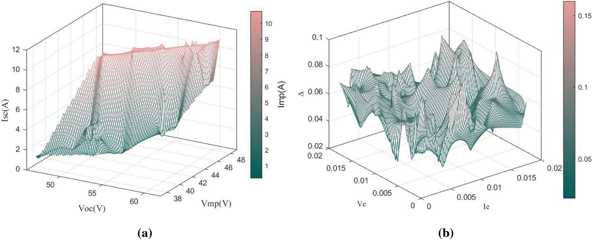
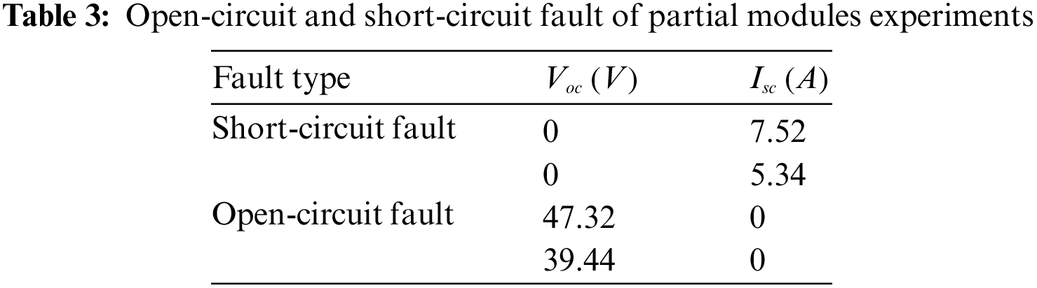
Figure 8: Results of experiments in minor aging fault operation: (a)
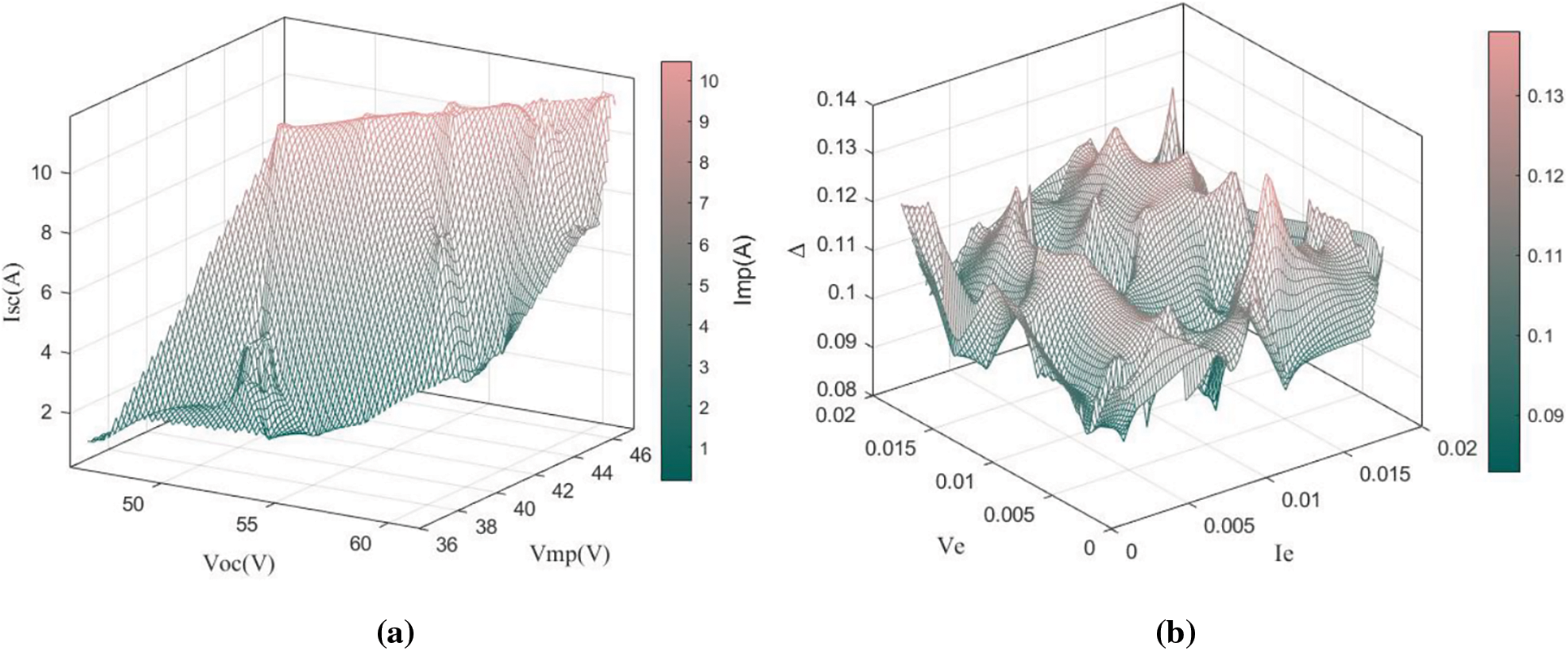
Figure 9: Results of experiments in severe aging fault operation: (a)
When minor aging fault and severe aging fault occurs, the corresponding feature arrays can be located by
4.5 Shadowing Fault Experiments
In this study, shadowing faults are simulated by shading 40% and 60% of the PV module, respectively.
Connect the three modules in series to form a group string. In the event of a shadow masking fault of the same magnitude in all three modules, each electrical parameter of the three modules is equal at that time, so the data from a single module is used to analyze the operating status of the string.
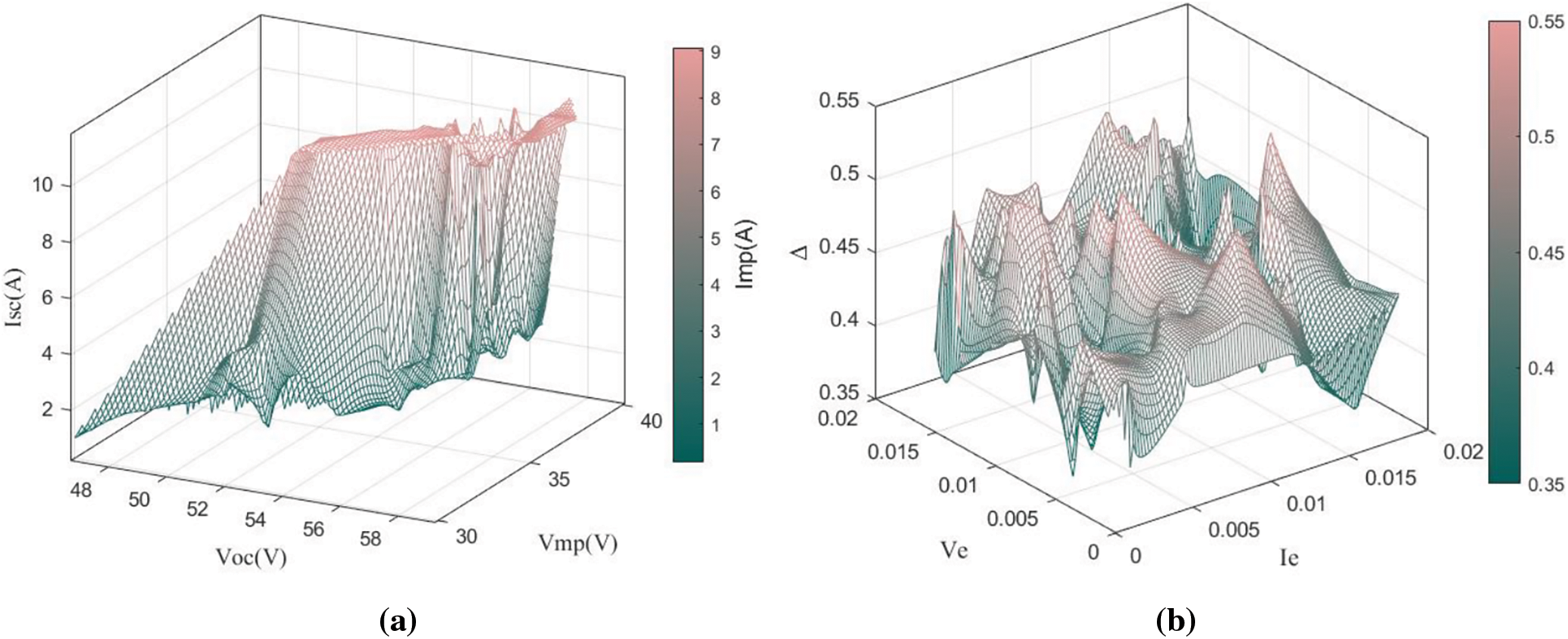
Figure 10: Results of experiments in 40% shadowing fault operation: (a)
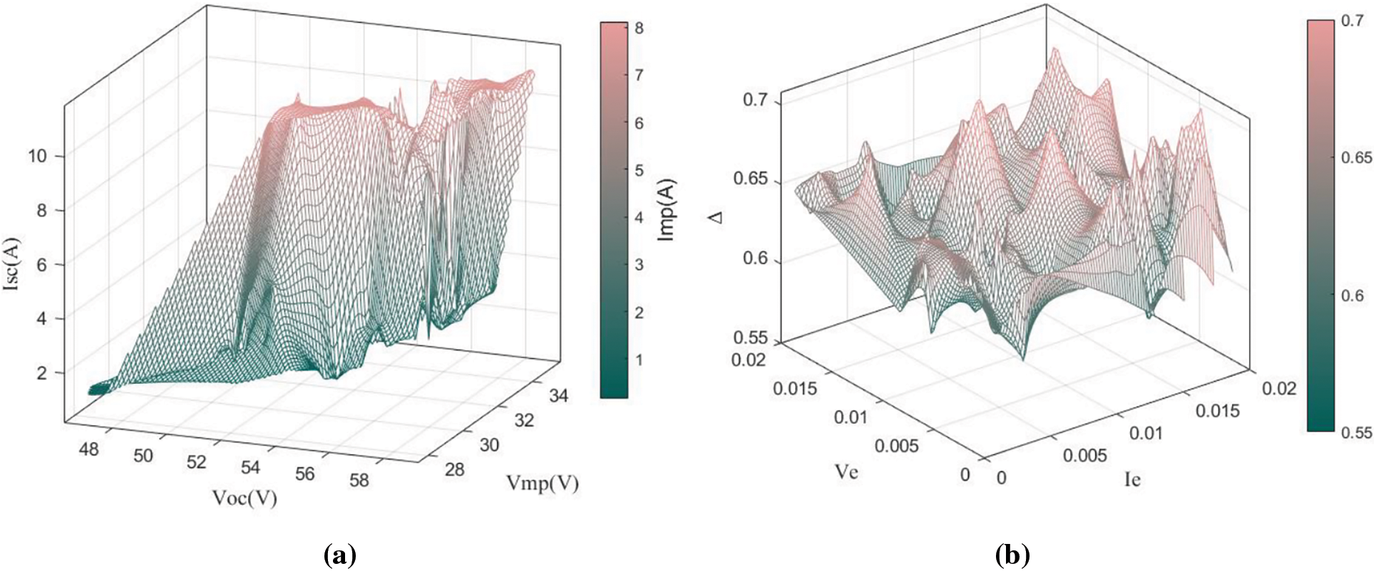
Figure 11: Results of experiments in 60% shadowing fault operation: (a)
When shadowing fault occurs, the corresponding feature arrays can be located by
Simulating a shadowing fault of partial modules by shadow masking the first module. The experimental data are shown in Table 4.
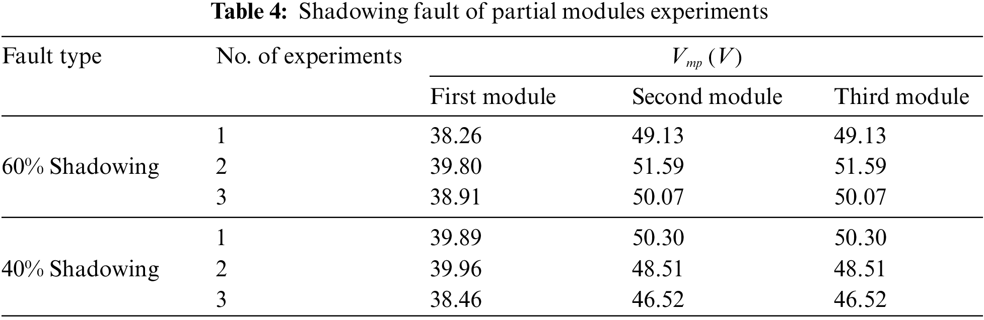
When the partial shading fault occurs on some modules, the maximum power point voltage of the faulty modules is much lower than that of the normally operating modules. Experimental data shows that the method proposed in this paper can accurately locate the faulty modules under partial shading fault conditions.
This paper proposes a novel real-time data-based monitoring method. This approach enables the monitoring of module or string-level photovoltaic systems solely through the analysis of electrical signals. In contrast to other methods, this approach only requires monitoring the open-circuit voltage, short-circuit current, and voltage and current at the maximum power point, without the need for environmental parameter monitoring. The experimental validation of the fault monitoring method proposed in this paper is carried out by the M81-400WT PV module. Experiments were conducted on PV modules in normal operation, aging failure, shadow shading failure, open circuit failure, and short circuit failure, respectively. The experiments prove that the method proposed in this paper does not misjudge during normal operation, and can determine open-circuit faults, short-circuit faults, aging faults, and shadow shading faults with shading area greater than 20%. which demonstrates the effectiveness of the method proposed in this paper. This method overcomes the disadvantage that the historical data-based method requires a large amount of experimental data to be obtained for effective monitoring, which makes it more suitable for diverse distributed PV scenarios. The method eliminates the mistakes generated by the aforementioned sensors and increases the precision of fault monitoring by doing away with the requirement for temperature and irradiance sensors from prior real-time data-based techniques. Additionally, it reduces the system cost for the two sensors mentioned above.
The shortcoming of this paper is that the feature array calculated based on the Lambert W function and iterative method has some inherent errors. To further increase the monitoring accuracy, we intend to develop a better calculating approach to produce a theoretical feature library with more precision. Meanwhile, the fault monitoring method proposed in this study is temporarily unable to classify aging faults and shadowing faults with a shadowing area of less than 20 percent. To be able to further classify the two faults, it is suggested that future research implement the function of extracting the peak number of the IV curve in the controller. Finally, this study is temporarily unable to monitor faults that do not affect the PV module output characteristics, such as rain ground faults, a type of fault that would be considered to be operating the module normally under existing monitoring methods. This type of fault will be analyzed separately in further studies to improve the monitoring system.
Acknowledgement: The authors acknowledge the support of CHNG Science and Technology Project (Design and Manufacture of Adaptive, Customized, Localised Autonomous Controllable Wind Turbines, and Remote Sea Power Transmission Technology) and 2023 Tianjin University’s “Rural Revitalization” Independent Innovation Fund Project-Online Fault Monitoring Methods and Empirical Research on Roof Photovoltaic Systems.
Funding Statement: This paper is supported by CHNG Science and Technology Project (HNKJ20-H54 Design and Manufacture of Adaptive, Customized, Localised Autonomous Controllable Wind Turbines, and Remote Sea Power Transmission Technology). This research is supported by 2023 Tianjin University’s “Rural Revitalization” Independent Innovation Fund Project-Online Fault Monitoring Methods and Empirical Research on Roof Photovoltaic Systems.
Author Contributions: The authors confirm contribution to the paper as follows: study conception and design: Huaxing Zhao; data collection: Huaxing Zhao; analysis and interpretation of results: Huaxing Zhao; draft manuscript preparation: Huaxing Zhao, Yanbo Che, Gang Wen, Yijing Chen. All authors reviewed the results and approved the final version of the manuscript.
Availability of Data and Materials: Data supporting this study are included within the article.
Conflicts of Interest: The authors declare that they have no conflicts of interest to report regarding the present study.
References
1. Kapucu, C., Cubukcu, M. (2021). A supervised ensemble learning method for fault diagnosis in photovoltaic strings. Energy, 227, 120463. [Google Scholar]
2. Guerriero, P., di Napoli, F., Vallone, G., d'Alessandro, V., Daliento, S. (2016). Monitoring and diagnostics of PV Plants by a wireless self-powered sensor for individual panels. IEEE Journal of Photovoltaics, 6(1), 286–294. [Google Scholar]
3. Chine, W., Mellit, A., Lughi, V., Malek, A., Sulligoi, G. et al. (2016). A novel fault diagnosis technique for photovoltaic systems based on artificial neural networks. Renewable Energy, 90, 501–512. [Google Scholar]
4. Ando, B., Baglio, S., Pistorio, A., Tina, G. M., Ventura, C. (2015). Sentinella: Smart monitoring of photovoltaic systems at panel level. IEEE Transactions on Instrumentation & Measurement, 64(8), 2188–2199. [Google Scholar]
5. Chen, Z., Wu, L., Cheng, S., Lin, P., Wu, Y. et al. (2017). Intelligent fault diagnosis of photovoltaic arrays based on optimized kernel extreme learning machine and I-V characteristics. Applied Energy, 204, 912–931. [Google Scholar]
6. Espinosa, A. R., Bressan, M., Giraldo, L. F. (2020). Failure signature classification in solar photovoltaic plants using RGB images and convolutional neural networks. Renewable Energy, 162, 249–256. [Google Scholar]
7. Hichri, A., Hajji, M., Mansouri, M., Abodayeh, K., Bouzrara, K. et al. (2022). Genetic-algorithm-based neural network for fault detection and diagnosis: Application to grid-connected photovoltaic systems. Sustainability, 14(17), 10518. [Google Scholar]
8. Voutsinas, S., Karolidis, D., Voyiatzis, I., Samarakou, M. (2022). Development of a multi-output feed-forward neural network for fault detection in photovoltaic systems. Energy Reports, 8, 33–42. [Google Scholar]
9. Ko, S. W., Ju, Y. C., Hwang, H. M., So, J. H., Jung, Y. S. et al. (2017). Electric and thermal characteristics of photovoltaic modules under partial shading and with a damaged bypass diode. Energy, 128, 232–243. [Google Scholar]
10. Bressan, M., El Basri, Y., Galeano, A. G., Alonso, C. (2016). A shadow fault detection method based on the standard error analysis of I-V curves. Renewable Energy, 99, 1181–1190. [Google Scholar]
11. Leva, S., Mussetta, M., Ogliari, E. (2019). PV module fault diagnosis based on microconverters and day-ahead forecast. IEEE Transactions on Industrial Electronics, 66(5), 3928–3937. [Google Scholar]
12. Ketjoy, N., Thanarak, P., Yaowarat, P. (2022). Case studies on system availability of PVP plants in Thailand. Energy Reports, 8, 514–526. [Google Scholar]
13. Gokmen, N., Karatepe, E., Silvestre, S., Celik, B. M., Ortega, P. (2013). An efficient fault diagnosis method for PV systems based on operating voltage-window. Energy Conversion and Management, 73, 350–360. [Google Scholar]
14. Forero, N., Hernandez, J., Gordillo, G. (2006). Development of a monitoring system for a PV solar plant. Energy Conversion and Management, 47(15–16), 2329–2336. [Google Scholar]
15. Silvestre, S., Silva, M. A., Chouder, A., Guasch, D., Karatepe, E. (2014). New procedure for fault detection in grid connected PV systems based on the evaluation of current and voltage indicators. Energy Conversion and Management, 86, 241–249. [Google Scholar]
16. Aljafari, B., Madeti, S. R. K., Satpathy, P. R., Thanikanti, S. B., Ayodele, B. V. (2022). Automatic monitoring system for online module-level fault detection in grid-tied photovoltaic plants. Energies, 15(20), 7789. [Google Scholar]
17. Pei, T., Hao, X. (2019). A fault detection method for photovoltaic systems based on voltage and current observation and evaluation. Energies, 12(9), 1712. [Google Scholar]
18. Li, G. Q., Jin, Y., Akram, M. W., Chen, X., Ji, J. (2018). Application of bio-inspired algorithms in maximum power point tracking for PV systems under partial shading conditions—A review. Renewable & Sustainable Energy Reviews, 81, 840–873. [Google Scholar]
19. Ishaque, K., Salam, Z. (2013). A review of maximum power point tracking techniques of PV system for uniform insolation and partial shading condition. Renewable & Sustainable Energy Reviews, 19, 475–488. [Google Scholar]
20. Ibrahim, H., Anani, N. (2017). Variations of PV module parameters with irradiance and temperature. Energy Procedia, 134, 276–285. [Google Scholar]
21. Piliougine, M., Oukaja, A., Sidrach-de-Cardona, M., Spagnuolo, G. (2021). Temperature coefficients of degraded crystalline silicon photovoltaic modules at outdoor conditions. Progress in Photovoltaics, 29(5), 558–570. [Google Scholar]
22. Mermoud, A., Lejeune, T. (2010). Performance assessment of a simulation model for PV modules of any available technology. 25th European PV Solar Energy Conference, pp. 6–10. Valencia, Spain. [Google Scholar]
23. Batzelis, E. I., Routsolias, I. A., Papathanassiou, S. A. (2014). An explicit PV string model based on the lambert W function and simplified MPP expressions for operation under partial shading. IEEE Transactions on Sustainable Energy, 5(1), 301–312. [Google Scholar]
24. Ketjoy, N., Mensin, P., Chamsa-ard, W. (2022). Impacts on insulation resistance of thin film modules: A case study of a flooding of a photovoltaic power plant in Thailand. PLoS One, 17, 1–17. [Google Scholar]
25. Sharma, V., Chandel, S. S. (2013). Performance and degradation analysis for long term reliability of solar photovoltaic systems: A review. Renewable & Sustainable Energy Reviews, 27, 753–767. [Google Scholar]
Cite This Article
 Copyright © 2024 The Author(s). Published by Tech Science Press.
This work is licensed under a Creative Commons Attribution 4.0 International License , which permits unrestricted use, distribution, and reproduction in any medium, provided the original work is properly cited.
 Downloads
 Citation Tools