
 Submit a Paper
 Propose a Special lssue
 Open Access
ARTICLE

Electromechanical Transient Modeling Analysis of Large-Scale New Energy Grid Connection
Department of Electrical Engineering, Hebei Vocational University of Technology and Engineering, Xingtai, 054000, China
* Corresponding Author: Shichao Cao. Email:
(This article belongs to the Special Issue: Renewable Energy Technologies for Sustainable Energy Production)
Energy Engineering 2024, 121(4), 1109-1125. https://doi.org/10.32604/ee.2023.043004
Received 19 June 2023; Accepted 08 August 2023; Issue published 26 March 2024
 View Full Text
 Download PDF
Abstract
The synchronous virtual machine uses inverter power to imitate the performance of the conventional synchronous machine. It also has the same inertia, damping, frequency, voltage regulation, and other external performance as the generator. It is the key technology to realize new energy grid connections’ stable and reliable operation. This project studies a dynamic simulation model of an extensive new energy power system based on the virtual synchronous motor. A new energy storage method is proposed. The mathematical energy storage model is established by combining the fixed rotor model of a synchronous virtual machine with the charge-discharge power, state of charge, operation efficiency, dead zone, and inverter constraint. The rapid conversion of energy storage devices absorbs the excess instantaneous kinetic energy caused by interference. The branch transient of the critical cut set in the system can be confined to a limited area. Thus, the virtual synchronizer’s kinetic and potential energy can be efficiently converted into an instantaneous state. The simulation of power system analysis software package (PSASP) verifies the correctness of the theory and algorithm in this paper. This paper provides a theoretical basis for improving the transient stability of new energy-connected power grids.Keywords
In recent years, with the rapid development of technologies such as cloud computing and big data, various large energy companies have gradually established their own cloud-based big data centers. It consumes more and more energy. Both the government and enterprises are beginning to study the low energy consumption of cloud data centers, advocating low-carbon, environment-friendly life, and green cloud computing. The resource scheduling and allocation method uses commercial servers supporting dynamic voltage and frequency adjustment technology to adjust the voltage used to save energy. Due to the increasing popularity of new energy sources, the proportion of conventional synchronous generators is getting smaller and smaller. The relative reduction of rotating reserve capacity and moment of inertia in the power system reduces the power grid's stable support and self-regulation ability against disturbance. This puts severe demands on the safety and stability of the power system. Energy storage systems based on power electronic devices have been widely used in power generation due to their adjustable characteristics. Reference [1] proposed a general prediction process for lithium battery state of health (SOH). It includes acquiring lithium-ion battery charge and discharge process data sets, data and feature processing, and algorithm selection. Reference [2] reviewed the sensing method. The system summarizes various measurement methods used to measure the above parameters of various new energy storage devices, such as batteries and supercapacitors.
Establishing a model that can reflect the operating characteristics of a large-scale battery energy storage system is crucial for studying the security and stability of the power grid after large-scale energy storage is connected to the grid. The transient stability research of a high-permeability power grid needs to establish a low-order, high-precision, open energy-mechanical transient mathematical model. Existing energy storage and grid characteristics simulations are mostly based on detailed models. It performs corresponding dimension reduction processing according to specific research objects. Reference [3] studied the electromechanical transient of the energy storage system on the PSASP simulation platform and considered the charging and discharging power of the battery. Reference [4] established a general energy storage model divided into station and local levels. It supports switching various control modes, such as constant power factor correction (PFC) control, droop control, and pressure control. Reference [5] proposed an outer loop control strategy. The control strategy includes both active and passive control methods. A force-machine transient model of an energy storage system based on “node current injection” is constructed by combining the model interface and constraints. This method can effectively control the power ripple in the three-phase grounding system. Reference [6] added active power feedforward control and charge and discharge power limitation based on reference [5]. The correctness of the model is verified by the simulation of smoothing new energy fluctuations. Reference [7] established a transient model of an energy storage system based on branch transient energy. This will make the system more accepting of this situation. Reference [8] aimed at realizing both energy regulation and energy regulation. Reference [9] proposed a multi-energy storage modeling method under multi-time scales and used it to improve the stable operation of large-scale new energy grids. The electromechanical transient and mid-term kinetic analysis of the lithium-ion battery energy storage system was carried out. Reference [10] studied the voltage stability control of the direct current (DC) transmission system with a synchronous condenser connected to the grid. The compensation effect of synchronous condenser connection on the bus voltage is obtained in the case of small, medium, and large disturbances. The effectiveness of the analytical method was verified. Reference [11] proposed the distribution method of energy storage power stations in the receiving end grid and the control method of electrochemical energy storage stations in different regions. Nevertheless, none of the above mentioned how to control the reactive power of the electrochemical energy storage plant in the event of a failure. The above energy storage modeling and control methods are attributed to the force-machine transient state. Most of them adopt conventional methods such as sagging to solve the above problems, and the potential of energy storage has not been fully utilized. Reference [12] proposed that the generator is the system’s most widely distributed and best dynamic reactive power compensation equipment, and the structure of the regulator and the generator is the same. The stability of the system and the safe and stable operation of the AC/DC grid can be improved by configuring a condenser in the receiving grid. Still, the connection between the electrochemical energy storage power station and the synchronous machine has not been studied in depth. Reference [13] researched the reactive power-voltage control strategy of improving the system’s transient voltage stability by prioritizing reactive and active power control. It concluded that energy storage has greater advantages when installed at dynamic loads. Reference [14] comparatively analyzed the influence of superconducting energy storage devices on the transient stability of the system under different installation locations and capacities. The results show that installing energy storage at the busbar of the generator that loses stability first has the best effect. Still, this conclusion has great limitations, and it depends on the rapid and accurate identification of the generator that loses stability first. However, the first unstable generators are different under different faults in the multi-machine system. Reference [15] designed the energy storage control strategy from the system transient kinetic energy perspective to the power output sensitivity of the energy storage power supply. Comparative analysis of the effect of energy storage under centralized and decentralized configurations concludes that a decentralized configuration is better than a centralized configuration. Reference [16] constructed a simplified first-order inertial link energy storage model considering the limiting factors of energy storage power. Still, the model is too simple to reflect the characteristics of energy storage power supply fully, and it is mainly aimed at system frequency adjustment, which is not fully applicable to transient processes.
A virtual machine consists entirely of software. It does not contain any hardware components. Virtual machines offer many unique advantages over physical hardware. This paper proposes an electromechanical transient modeling method for energy storage under the control of a virtual generator set, which is suitable for transient stability analysis of large-scale power systems. A virtual generator set controller is constructed based on the virtual governor and virtual excitation controller as the core, combined with the mathematical models of rotor mechanics and stator electricity. Corresponding simplification methods are proposed for multiple timing components such as the energy storage primary body model, current inner loop controller, and converter. According to the node current injection method, the energy conversion between the modules is carried out, and the transient model of the energy storage system based on the branch transient potential energy control is constructed. By controlling the transient potential energy of the branch, the ability to withstand the transient potential energy of the system is improved to improve the transient stability of the system. The electromechanical transient simulation of new energy grid-connected based on a virtual machine proposed in this paper is compatible with the power system.
Furthermore, it exists independently of the hardware system. So, the virtual machine does not need to control the transient potential energy of the entire network, and the method only needs to use energy storage to control the transient potential energy of the critical branch. The control signal is easy to extract, and the energy ratio index is further improved to evaluate the energy storage and control energy effect.
2 Control Theory of Virtual Synchronizer Technology
Virtual synchronous generator technology simulates the grid-connected inverter so that the new energy unit has the characteristics of inertia, damping, frequency regulation, and voltage regulation. This provides frequency and voltage support for new energy units. Thus, the operation adaptability, safety, and stability of new energy units connected to the power grid can be improved. A virtual synchronous generator (VSG) topology is shown in Fig. 1. The energy storage device uses a VSG control mode parallel frequency converter. The electric energy enters the power system through the LCL filter and the output line.
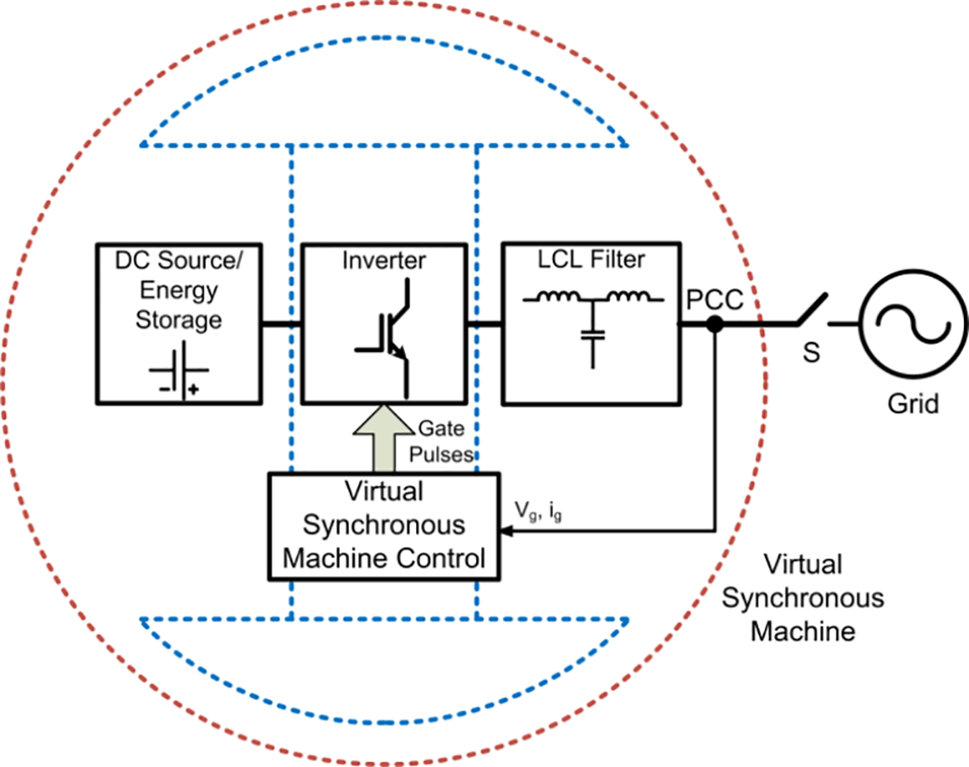
Figure 1: Virtual synchronous machine control structure diagram
It can be seen from Fig. 1 that the control model of the energy storage converter is composed of outer loop power control and current inner loop control. The outer loop control is the virtual synchronous machine control. It contains virtual governor, rotor mechanical equations, virtual field regulator, and stator electrical equations. VSG’s active power control consists of a virtual regulator and a rotor system. Virtual regulators mimic regulators from external features. Thus, the busy work and the system’s frequency show a “drop” feature.
The reactive power control of VSG is also a virtual magnetic field regulator. It is expressed in Eq. (3). The voltage and reactive power differences of the virtual generator are used as feedback to simulate the internal potential of the generator.
The VSG electromagnetic part is modeled on the stator electrical part. The electromagnetic wave equation in Eq. (4) can be obtained by converting its terminal voltage to an axis
Figure 2: Grid-connected equivalent circuit of energy storage converter
The transmission line must be inductive to decouple VSG’s active and reactive power. Therefore, if the hypothetical resistance value
Active power and reactive power injected by the grid-connected converter can be obtained by expanding the above equation:
3 Virtual Synchronous Motor Control to Establish an Energy Storage Model
3.1 Modeling Architecture of Energy Storage Device
The structure of the energy storage virtual synchronous machine is shown in Fig. 3. Its structure mainly includes two parts, an energy storage unit and an inverter unit, and represents three phases with a single phase. Pulse-width modulation (PWM) is pulse width modulation.
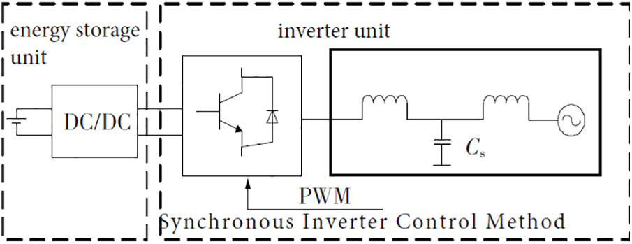
Figure 3: Grid connection structure of the virtual synchronous machine
In Eqs. (11) to (14),
The fundamental voltage at the exit of the inverter is expressed in the equation
The equation for calculating the phase voltage base wave amplitude
Substituting Eqs. (14) and (17) into Eq. (12) yields:
Substituting Eqs. (14) and (17) into Eq. (13) yields:
The energy storage device can adjust charging and discharging power in real-time and has a peak clipping capability, twice its installation capacity. For both the AC grid and the DC grid, the energy storage power station has a solid ability to improve the stability and flexibility of the grid. For the former energy storage power station, it can reduce valley charging, adjust the system frequency, and provide reactive voltage support. For the latter, the electrochemical energy storage power plant can also provide sufficient reactive power for the converter station and enhance the ability of the converter station to resist commutation failure. The energy storage power station mainly comprises a battery room, transformer booster box, 10 kV confluence box, intelligent main control room, SVG room, substation, and other supporting equipment. The power station has a station-side monitoring system, intelligent network load interactive terminal, synchro phasor measurement device, anti-islanding protection and frequency voltage emergency control device and intelligent auxiliary control system. Synchronous motors need to be used for reactive power compensation of the grid, and they operate in a unique way of no-load operation when connected to the grid. This mode of operation can improve power factor and improve power supply performance. It can be seen from the analysis that the energy storage virtual synchronous machine also has the special operation mode of the synchronous machine. In response to DC commutation failure, the energy storage virtual synchronous machine can continuously provide reactive power to the system to support the DC bus voltage and prevent commutation failure when the DC bus voltage drops rapidly when the system fails. In the HVDC system, the thyristor on the rectifier side has sufficient turn-off time. The thyristor on the inverter side has insufficient turn-off time, which will cause the two ends of the thyristor that were not completely turned off to bear the forward voltage. The thyristor will be turned on again, so the commutation failure mainly Occurs in the thyristor of the converter station on the inverter side. If the commutation voltage drop of the HVDC system is supported, the commutation failure can be significantly suppressed.
The electromechanical transient energy storage system model includes a control, ontology, and model interface. Energy storage and conversion device is an integral part of energy storage. Its main objective is to realize effective voltage control by inverter-frequency, amplitude, and phase. The direct current energy of the energy storage unit is converted to the alternating current energy suitable for the power grid. It can be divided into outer ring regulation and inner ring regulation. The outer loop control system of the equipment is the central control system. Read bus frequency
3.2 Control Model of Energy Storage Converter
The internal loop control architecture of the converter is shown in Fig. 4. This paper focuses on PI chain-based feedforward decoupling inner loop and VSC systems. The input voltage reference of the inner loop system is adjusted so that the current axis component
Figure 4: Control after decoupling of the inner ring of the shunt converter
Axis
It can be converted into a first-order inertia chain by using the pole-zero cancellation principle, and the power characteristic equation can be expressed as
3.2.2 Modeling of Energy Storage Converter
According to the above virtual synchronous machine control model and simplified inner loop control, the energy storage converter control model can be used, as shown in Fig. 5.
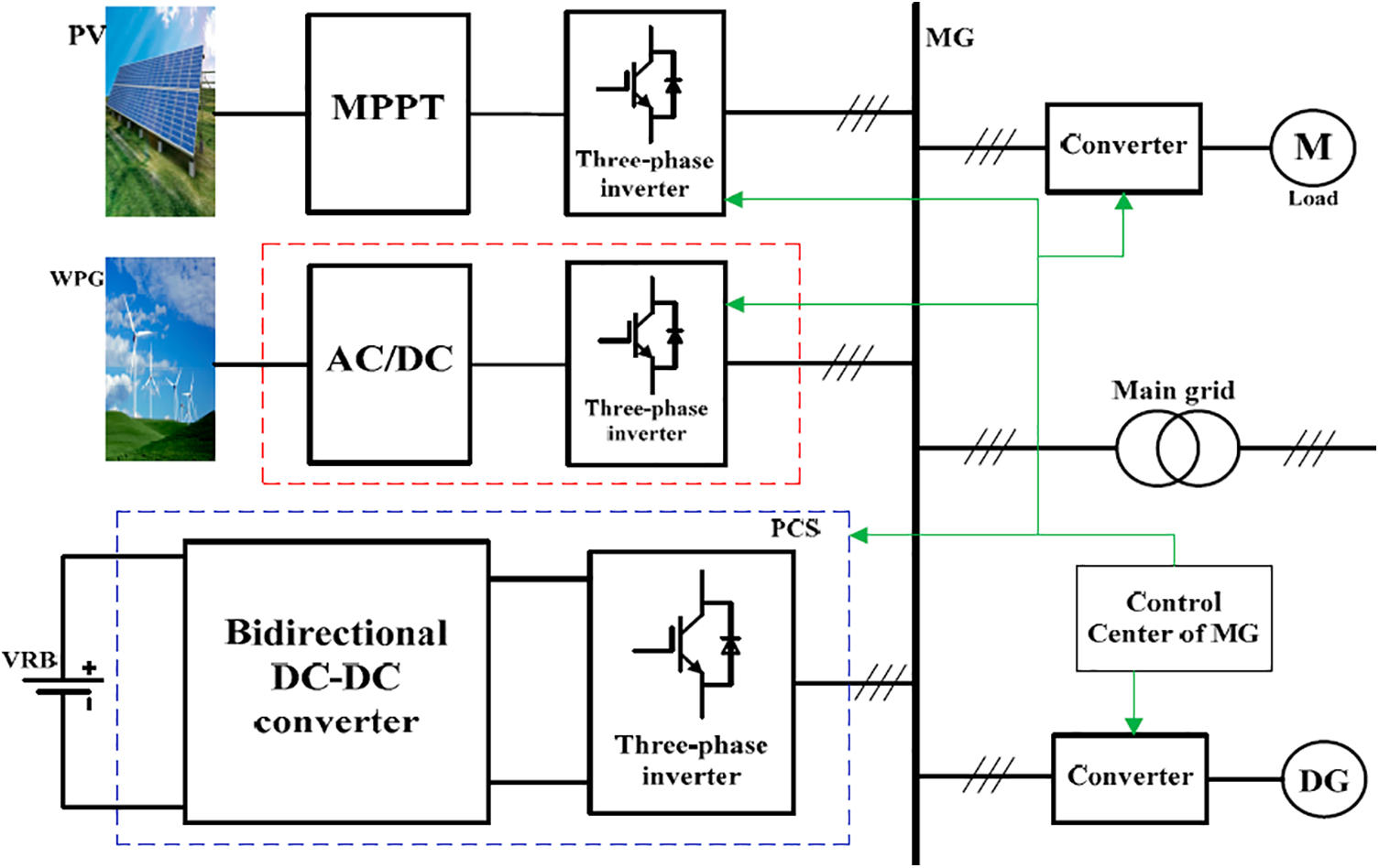
Figure 5: Control model of energy storage converter
The active regulation mainly includes the virtual governor, rotor mechanical equation and active power output. OMB here represents the frequency of the bus.
3.3 Energy Storage Ontology Model
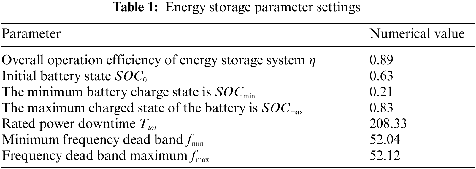
The energy storage unit differs in charge and discharge rate, power grade and other parameters. The influence of charging conditions on energy storage units is considered in the range of force-electric short time. This paper proposes a nonlinear and time-invariant theoretical model of battery charging and discharging characteristics and parameters based on transient responses of power electronic systems. A linear line can represent its external properties. The modeling of the energy accumulator is equivalent to the setting of the related limit link of the frequency converter [17]. It includes in-charge state calculations, capacity limits, dead zone chaining, operating efficiency, charge and discharge power limits, and converter capacity limits.
(1) The charged state of energy storage refers to the percentage of the available power and the maximum power in the rechargeable pool group. It reflects the power of the battery. It plays an essential role in battery utilization efficiency and service life. The system on chip (SOC) is estimated by ampere-hour measurement, open-circuit voltage, neural network, Kalman filter, etc. A new ampere-hour calculation method with wide application and simple operation is presented [18]. (2) Storage capacity limits the charging status of the storage unit should be kept within a reasonable range. Avoid damaging the battery due to overcharging and discharging. (3) Charging and releasing power is restricted due to the limitation of the energy storage unit. As a result, the energy storage system has upper and lower limits of charge and discharge power. (4) The operating efficiency of the storage device includes the operating efficiency of the power electronic device and the operating efficiency. This paper simplifies the influence of the change in the battery’s state of charge on the efficiency of the energy storage operation [19]. (5) Converter capacity limit refers to the converter having a specific reactive power regulation ability because most of the energy storage active power output is not running at the power level. Usually, active power is the main, and reactive power is a supplement regulation mode. (6) The function of the dead zone link is a manually set operating boundary. The paper prevents the service life of the energy storage device from being shortened due to repeated charging and discharging when the system is slightly disturbed. Its limitations according to the above principles can be listed as follows. Fig. 6 is a simulation power model analysis and research.
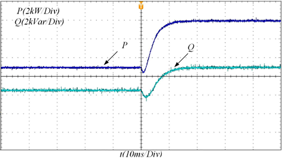
Figure 6: Simulation power model analysis and research
3.4 Analysis of Grid Connection Model
Active power
The comparison of experimental results shows that the experimental data obtained from the experimental platform constructed in this article is consistent with the simulated data. When using this control method, they can all meet the output requirements of the system, but compared to using model predictive control, its output voltage control effect is worse than using model predictive control, which can also be seen from the output voltage. At the same time, due to the introduction of inertia and damping in the VSC system control, the output current overshoot will be smaller when the load is switched than when using conventional control, but there will still be some overshoot phenomenon, and the output power overshoot will also be smaller. The advantage of the new VSC is that the new optimization objective function can ensure the accuracy of voltage tracking while also taking into account the error of current tracking, thereby ensuring the accuracy of voltage tracking and improving the accuracy of current tracking. In addition, due to the introduction of the VSC system control output tracking voltage reference and the setting of current limiting limits in the cost function, its output current and output power are shallow during load switching. Therefore, it can handle load switching well, achieving better power tracking and ensuring the safe and stable operation of the system. The experiment shows that this method is correct and effective.
4.1 Model Validity Verification
The energy storage process’s dynamic characteristics are simulated using the WEPRI7 node system. A three-phase short circuit fault occurs on the side of line B4-B3 near bus B4 at 0 s. The fault was removed 0.06 s later. Install an energy storage device on the busbar B1. The maximum power is 100 megawatts. It has a capacity of 1000 megajoules. The initial SOC value is 0. Fig. 7 shows the relative power angle curve of the motor delivered before energy storage access and at different access times. The power angle of the system is unstable after the fault occurs. The method can effectively suppress the relative power angle vibration of the unit and ensure the instantaneous stability of the unit. It shows the effectiveness of the energy storage model based on transient situation control.
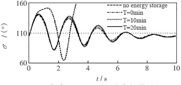
Figure 7: Relative power angle curve of generator
The response curve of the energy storage device under different grid-connection times is shown in Fig. 8. Under different grid-connection times. The accumulator plays a consistent role in improving the transient stability of the power grid. In contrast, the accumulator’s response is very different. When T = 10 min, it can respond quickly to control signals and make the SOC of energy storage itself closer to 0.5, thus improving the system’s stability [22]. The loss of energy storage is effectively reduced, and the utilization rate of energy storage is increased. Therefore, it is necessary to set up an energy storage access control device.
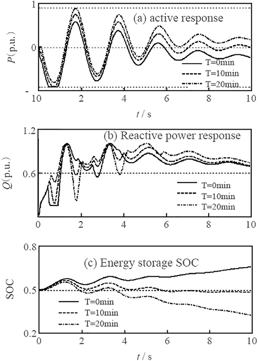
Figure 8: Response curve of energy storage system
4.2 Model Application Simulation Analysis
Simulation and analysis of energy storage using PSASP software. The unit is a typical structure. The three-phase short-circuit fault is set in busbar 3, line 2*–12 and line 15–16*, respectively. The “*” indicates the failed near-end busbar. The defect elimination rate of this method is 0.18, 0.22, 0.17 s. Set the maximum energy storage power at 500 MW. It has a capacity of 8 gigajoules.
Furthermore, install it on buses 1, 9. The relative power Angle curve and energy ratio index ERI curve of the generator before and after the energy storage system is connected based on time domain simulation, which is shown in Figs. 9–11. Table 2 shows the critical branch stability indexes of the system before and after the energy storage is connected under different faults.
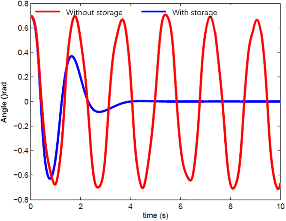
Figure 9: Bus 3 relative motor power angle curve under fault
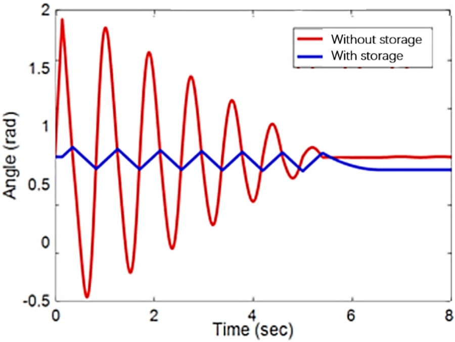
Figure 10: Line 15–16* motor relative power angle curve under failure
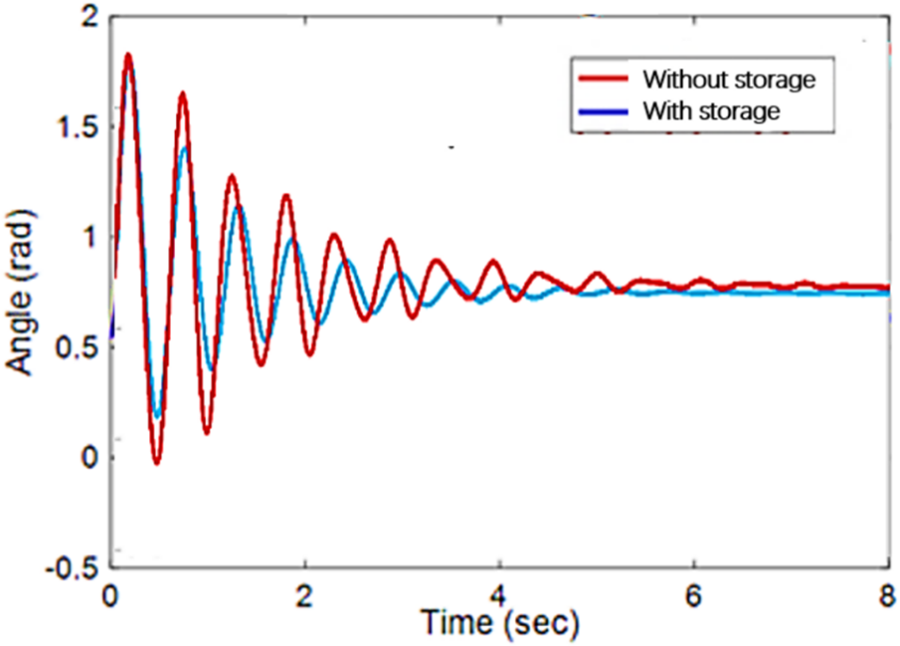
Figure 11: Relative power angle curve of line 2*–12 motor under fault operation
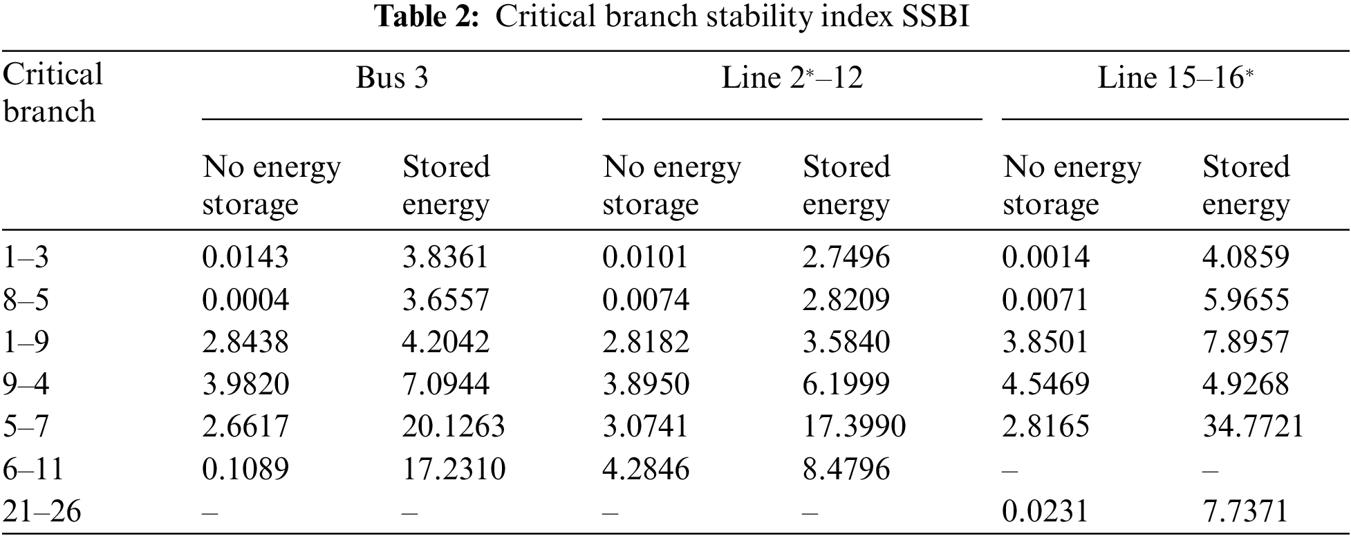
It can be seen from Figs. 9–11 that when busbar three and line 2*–12 fail, the system presents two significant instability graphs. However, when the 15–16* line fails, it shows multigroup instability. Whether the system is two-group unstable or multi-machine group unstable, the instability situation of the system can be effectively suppressed after the energy storage is added [23]. The relative power angle, Δ of the motor, is steady and does not continue to increase. At the same time, it can be seen from Table 2 that the method of improving transient stability with energy storage proposed in this paper can effectively improve the stability of critical cut-set branches. The key points (1–2, 8–9) can effectively control the transient energy through energy storage. The results are consistent with the regulatory purpose of energy storage.
Table 2 shows that the system undergoes an incomplete energy transition within 2 s when not connected to an energy storage device. The speed of energy conversion will become slow, and it is impossible to absorb all the kinetic energy. As a result, the system’s kinetic and potential energy continues to increase, and the kinetic energy increases faster than the potential energy. Therefore, its energy level ratio tends towards 0. After the accumulator is introduced into the system, its conversion rate is accelerated. The maximum resistance index increases significantly. Storage devices increase the rate of energy conversion. Its function is to use up all the energy. Its effect is to make the system absorb all the kinetic energy. Due to the conservation of system energy after a fault, the kinetic energy and potential energy are continuously converted to each other, resulting in the final system stability.
A new method of modeling energy storage devices using synchronous virtual machines is proposed. Examples simulate the transient characteristics of the power system under various control modes. The force-machine transient mathematical model of an energy storage system based on a virtual synchronous motor is established. The designed energy storage device is simulated in PSASP software. It has a more accurate trend of external characteristics by simulating various working conditions and analyzing transient characteristics. The results show that the energy storage model is correct and effective. This model can reflect the transient performance and energy storage performance of synchronous motor wells. The “virtual synchronous generator” technology can make the energy storage and its converter have the characteristics of a synchronous generator. It can realize real-time adjustment of output power and voltage, effective smoothing of power fluctuations, active power, and reactive power without changing the control strategy-maintenance of work and power balance, adjustment of grid frequency and voltage.
Acknowledgement: None.
Funding Statement: The authors received no specific funding for this study.
Author Contributions: The authors acknowledge the contributions to this article as follows: Study conception and design: Shichao Cao; Data collection: Yonggang Dong; Results analysis and interpretation: Xiaoying Liu; Manuscript preparation: Shichao Cao. All authors reviewed the results and approved the final version of the manuscript.
Availability of Data and Materials: The data supporting this study’s findings are available on request from the corresponding author. The data are not publicly available due to privacy or ethical restrictions.
Conflicts of Interest: The authors declare no conflicts of interest to report regarding the present study.
References
1. Zhang, M., Yang, D., Du, J., Sun, H., Li, L. et al. (2023). A review of SOH prediction of Li-ion batteries based on data-driven algorithms. Energies, 16(7), 3167–3195. [Google Scholar]
2. Yi, Z., Chen, Z., Yin, K., Wang, L., Wang, K. (2023). Sensing as the key to the safety and sustainability of new energy storage devices. Protection and Control of Modern Power Systems, 8(1), 1–22. [Google Scholar]
3. You, J., Fu, R., Liang, H., Yang, D., Lin, Y. et al. (2022). Energy conservation model for electromechanical transient characteristics of electromagnetic actuators. IEEE Transactions on Energy Conversion, 37(4), 2535–2545. [Google Scholar]
4. Zhang, S. Q., Tang, S. P., Yu, S. Q., Lu, X., Zhang, H. (2023). Multiple time scale characteristics of converter network and simulation application of its different fineness models. Journal of Tsinghua University (Science and Technology), 63(1), 78–93 (In Chinese). [Google Scholar]
5. Ye, H., Gao, F., Pei, W., Kong, L. (2021). Wave function and multiscale modeling of MMC-HVDC system for wide-frequency transient simulation. IEEE Journal of Emerging and Selected Topics in Power Electronics, 9(5), 5906–5917. [Google Scholar]
6. Ohlsson, F., Johannisson, P., Rusu, C. (2021). Geometrical nonlinearities and shape effects in electromechanical models of piezoelectric bridge structures. International Journal of Energy and Environmental Engineering, 12(4), 725–738. [Google Scholar]
7. Rejabov, Z. M., Boihanov, Z. U. U. (2021). Dynamic models of an electromechanical electric drive system of an asynchronous motor. The American Journal of Engineering and Technology, 3(4), 134–139. [Google Scholar]
8. Jing, L., Pan, Y., Wang, T., Qu, R., Cheng, P. T. (2021). Transient analysis and verification of a magnetic gear integrated permanent magnet brushless machine with Halbach arrays. IEEE Journal of Emerging and Selected Topics in Power Electronics, 10(2), 1881–1890. [Google Scholar]
9. Назарова, О. С., Осадчий В. В., Шульженко, С. С. (2022). Computer modeling of electromechanical system of two-speed elevator. Herald of Advanced Information Technology, 5(2), 133–142. [Google Scholar]
10. Kulasza, M. A., Annakkage, U. D., Karawita, C. (2021). Extending the frequency bandwidth of transient stability simulation using dynamic phasors. IEEE Transactions on Power Systems, 37(1), 249–259. [Google Scholar]
11. Adeen, M., Milano, F. (2021). On the impact of auto-correlation of stochastic processes on the transient behavior of power systems. IEEE Transactions on Power Systems, 36(5), 4832–4835. [Google Scholar]
12. Wang, Y., Lu, C., Wu, P., Zhang, X., Su, Y. et al. (2021). Online realization of an ambient signal-based load modeling algorithm and its application in field measurement data. IEEE Transactions on Industrial Electronics, 69(7), 7451–7460. [Google Scholar]
13. Chen, Y., Deng, C., Zhao, Y. (2021). Coordination control between excitation and hydraulic system during mode conversion of variable speed pumped storage unit. IEEE Transactions on Power Electronics, 36(9), 10171–10185. [Google Scholar]
14. Semenov, A. S., Trapp, J., Nöthe, M., Eberhardt, O., Kieback, B. et al. (2021). Thermo-electro-mechanical modeling of spark plasma sintering processes accounting for grain boundary diffusion and surface diffusion. Computational Mechanics, 67(5), 1395–1407. [Google Scholar]
15. Nnoli, K. P., Kettemann, S. (2021). Spreading of disturbances in realistic models of transmission grids in dependence on topology, inertia and heterogeneity. Scientific Reports, 11(1), 1–17. [Google Scholar]
16. Liu, W., Han, J. L., Tomek, J., Bub, G., Entcheva, E. (2023). Simultaneous widefield voltage and dye-free optical mapping quantifies electromechanical waves in human induced pluripotent stem cell-derived cardiomyocytes. ACS Photonics, 10(4), 1070–1083. [Google Scholar] [PubMed]
17. Kuznetsov, O. N., Zubkova, I. S., Averyanov, D. A. (2022). A global-energy-network equivalent for calculation of transient stability. Russian Electrical Engineering, 93(1), 46–52. [Google Scholar]
18. Iannacci, J. (2021). Coupled electromechanical and electromagnetic simulation of radio frequency microelectromechanical-systems (RF-MEMS) based on compact models approach. Microsystem Technologies, 27(1), 59–67. [Google Scholar]
19. Cheng, T., Lin, N., Dinavahi, V. (2022). Hybrid parallel-in-time-and-space transient stability simulation of large-scale AC/DC grids. IEEE Transactions on Power Systems, 37(6), 4709–4719. [Google Scholar]
20. Cunha Jr,A., Pereira, M., Avanço, R., Tusset, A. M., Balthazar, J. M. (2022). On the reduction of nonlinear electromechanical systems. Meccanica, 57(10), 2679–2697. [Google Scholar]
21. Tang, W., Hu, J., Zhang, R., Chen, X., Yang, Z. (2021). Coupling characteristics of DFIG-based WT considering reactive power control and its impact on phase/amplitude transient stability in a rotor speed control timescale. CSEE Journal of Power and Energy Systems, 8(2), 511–522. [Google Scholar]
22. Canova, A., Gruosso, G., Quercio, M. (2021). Characterization of electromagnetic device by means of spice models. International Journal Emerging Technology and Advanced Engineering, 11(9), 12–22. [Google Scholar]
23. Tzounas, G., Dassios, I., Milano, F. (2022). Frequency divider as a continuum. IEEE Transactions on Power Systems, 37(6), 4970–4973. [Google Scholar]
Cite This Article
 Copyright © 2024 The Author(s). Published by Tech Science Press.
This work is licensed under a Creative Commons Attribution 4.0 International License , which permits unrestricted use, distribution, and reproduction in any medium, provided the original work is properly cited.
 Downloads
 Citation Tools