
 Submit a Paper
 Propose a Special lssue
 Open Access
ARTICLE

Desired Dynamic Equation for Primary Frequency Modulation Control of Gas Turbines
1 Thermal Power Center, Jiangsu Frontier Electric Technology Co., Ltd., Nanjing, 211102, China
2 School of Energy and Power Engineering, Nanjing Institute of Technology, Nanjing, 211167, China
* Corresponding Author: Xiaobo Cui. Email:
Energy Engineering 2024, 121(5), 1347-1361. https://doi.org/10.32604/ee.2023.045805
Received 08 September 2023; Accepted 23 November 2023; Issue published 30 April 2024
 View Full Text
 Download PDF
Abstract
Gas turbines play core roles in clean energy supply and the construction of comprehensive energy systems. The control performance of primary frequency modulation of gas turbines has a great impact on the frequency control of the power grid. However, there are some control difficulties in the primary frequency modulation control of gas turbines, such as the coupling effect of the fuel control loop and speed control loop, slow tracking speed, and so on. To relieve the abovementioned difficulties, a control strategy based on the desired dynamic equation proportional integral (DDE-PI) is proposed in this paper. Based on the parameter stability region, a parameter tuning procedure is summarized. Simulation is carried out to address the ease of use and simplicity of the proposed tuning method. Finally, DDE-PI is applied to the primary frequency modulation system of an MS6001B heavy-duty gas turbine. The simulation results indicate that the gas turbine with the proposed strategy can obtain the best control performance with a strong ability to deal with system uncertainties. The proposed method shows good engineering application potential.Keywords
Due to the advantages of fast response, high efficiency, and cleanliness, gas turbine units are becoming a key component in building new-type power system in China. In order to cope with the load and frequency fluctuations caused by the large-scale integration of new energy power sources such as photovoltaic power and wind power into the power grid, gas turbine units need to have a strong primary frequency modulation (PFM) capability, which are of great significance for the safe operation and frequency stability of the power grid.
In order to further enhance the PFM capability of gas turbine units, many scholars have conducted extensive research in terms of control strategy designs, control logic optimizations, and other aspects. In reference [1], a medium-pressure heating throttling scheme was proposed to optimize the PFM logic in order to increase the margin of load regulation for gas turbine units. In reference [2], a significant improvement in the response speed of the unit’s PFM was achieved by optimizing the speed control mode of the main control system, reducing the frequency modulation dead-zone and increasing the frequency modulation amplitude. In reference [3], the response speed of the unit to PFM commands was improved by adding locking logic and modifying frequency difference signals. For the problem that the response index of the PFM cannot meet the requirements of the power grid, an optimization logic scheme based on feedforward limiting and compensation for power closed-loop was proposed in reference [4] to improve the PFM capability.
The actual control logic of PFM in gas turbines is mostly based on the Proportional-Integral (PI) control strategy [5], due to the advantages of PI controllers, such as simple structure, excellent performance, simple implementation, and clear parameter meanings [6]. In addition, in order to further enhance the PFM capability of gas turbines, a new method based on Active Disturbance Rejection Control (ADRC) was proposed in reference [7], where ADRC parameters are optimized through a multi-objective genetic algorithm to achieve the improvement of gas turbine PFM capability. In addition, control strategies based on neural networks are also studied in the PFM system of gas turbines [8]. Due to the large amount of computation requirements for advanced control strategies, their engineering implementation still faces certain challenges. However, there is still no lack of potential for large-scale engineering applications given the arithmetic capabilities of current gas turbine control platforms [9]. For a long time in the future, the PI control strategy will still occupy the dominant position in the PFM system of gas turbines [10]. To enhance the control performance of PI in the PFM system of gas turbines, it is necessary to optimize the structure and parameter tuning of PI controllers. The DDE-PI controller has received increasing attention due to its adjustable parameters with feedforward coefficients, which can effectively balance the contradiction between tracking and anti-disturbance performance of closed-loop systems [11]. The DDE-PI controller further enhances the robustness of the closed-loop system while retaining the advantages of the classical PI strategy, and has been well applied in the super-heated steam temperature system [12] and the high-pressure heater water level system [13]. Running data show that DDE-PI has strong application potential.
In this study, a DDE-PI control strategy for the PFM system of a gas turbine is designed. Firstly, the composition of the MARK V heavy-duty gas turbine PFM system is introduced, and the control characteristics of the system are analyzed. Then, the DDE-PI control strategy is introduced, the calculation of the parameter stability domain is provided, and the practical parameter tuning procedure is summarized. Next, the DDE-PI control strategy proposed in this study is applied to the PFM control of MARK V heavy-duty gas turbine units. The simulation results show that the gas turbine unit using the method proposed in this study can ensure optimal PFM capability and a strong ability to cope with system uncertainty. Finally, the work of this study is summarized.
2 PFM Model of MS6001B Heavy-Duty Gas Turbine
A frequency modulation system of an MS6001B heavy-duty gas turbine based on the MARK V control system was introduced in reference [14]. Taking the speed control system, fuel control system, and acceleration control system into consideration, the structural diagram of the PFM control system is shown in Fig. 1, where the acceleration control speed is generally kept constant in the control system. Reference [14] provides the physical meanings and corresponding values of some model parameters in Fig. 1, as shown in Table 1. The models of the other links are as follows:
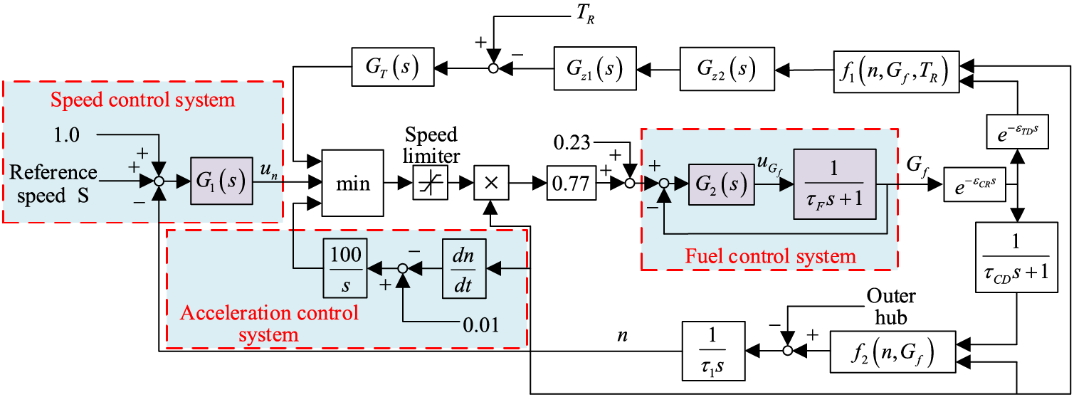
Figure 1: PFM control model of an MS6001B heavy-duty gas turbine
In addition, the controllers for speed and fuel in the system are
The system model is built based on a liquid-fueled circulating single-shaft gas turbine, with a rated speed of 5100 r/min and rated power of 359 MW. The exhaust temperature, rated inlet temperature, and speed governing droop of the gas turbine unit are 550°C, 15°C, and 4%, respectively [5].
From Fig. 1, the output of the fuel control system of the gas turbine goes through a pure lag link and an inertia link. Combined with the integration effect, the speed of the gas turbine is obtained and serves as the output value of the speed control system, which is algebraically calculated as the set value of the fuel control system. This means that there is a coupling effect between the speed control system and the fuel control system due to their interaction. Note that
3 Desired Dynamic Equation PI (DDE-PI) Controller
Consider a general system described by the following equation:
where
The following state space form is obtained by the state transformation of Eq. (4):
where
Define the observation extended state as:
where
when the relative order of the controlled object q equals 2, Eq. (5) is transformed to:
The DDE strategy for the closed-loop system is designed as:
Combining Eq. (8), it can be obtained that the designed control law is:
where
where
Considering the disturbance observer in Eq. (11), it can be obtained that:
Eq. (14) can be obtained by integrating both sides of Eq. (13).
Considering Eqs. (13), (14) is equivalent to:
Considering that the set value
Similarly, when the controlled object turns out to be a system with a relative order of 1, its control law can be obtained as:
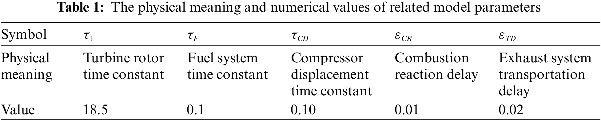
Thus, it is known that PI/PID control based on DDE is a two-degree freedom structure containing a feedforward and feedback controller, which is shown in Fig. 2 [16],
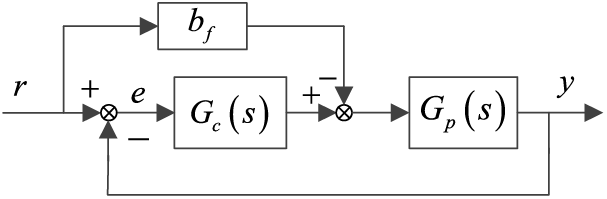
Figure 2: Control structure of DDE-PI/PID
Since differentiation introduces amplification of the manipulated variable by measurement noise, DDE-PI controllers are adopted as
4 Parameter Tuning of DDE-PI Controller
According to the Mason transformation formula, the closed-loop system transfer function from
As is shown in Eq. (17), the feedforward controller does not appear in the characteristic equation of the closed-loop system, that is to say
The frequency domain response of the controlled object described in Eq. (4) is decipted as follows [17]:
where
The stability domain of the DDE-PI controller can be obtained using the D-partitioning method. The stability domain boundary of PI controller includes nonsingular boundary
Combining
The parameters of the DDE-PI controller should be reasonably selected from the stability region described in Eq. (21). Through extensive simulations, the parameter tuning procedure is summarized as follows:
1. Determine the coefficients of the desired dynamic PI equation
2. Choose a larger
3. Reduce
4. If satisfactory control performance cannot be achieved, repeat step 2 to step 3 with appropriate increase of
The parameter tuning procedure of the DDE-PI controller is shown in Fig. 3. It can be observed that the proposed tuning procedure has strict logic and simple steps even though it needs trials and errors.
Figure 3: Parameter tuning procedure of DDE-PI
To illustrate the simplicity and effectiveness of the proposed tuning method, take
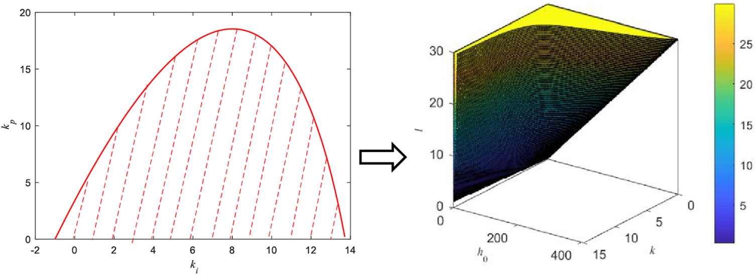
Figure 4: The stability region of DDE-PI for
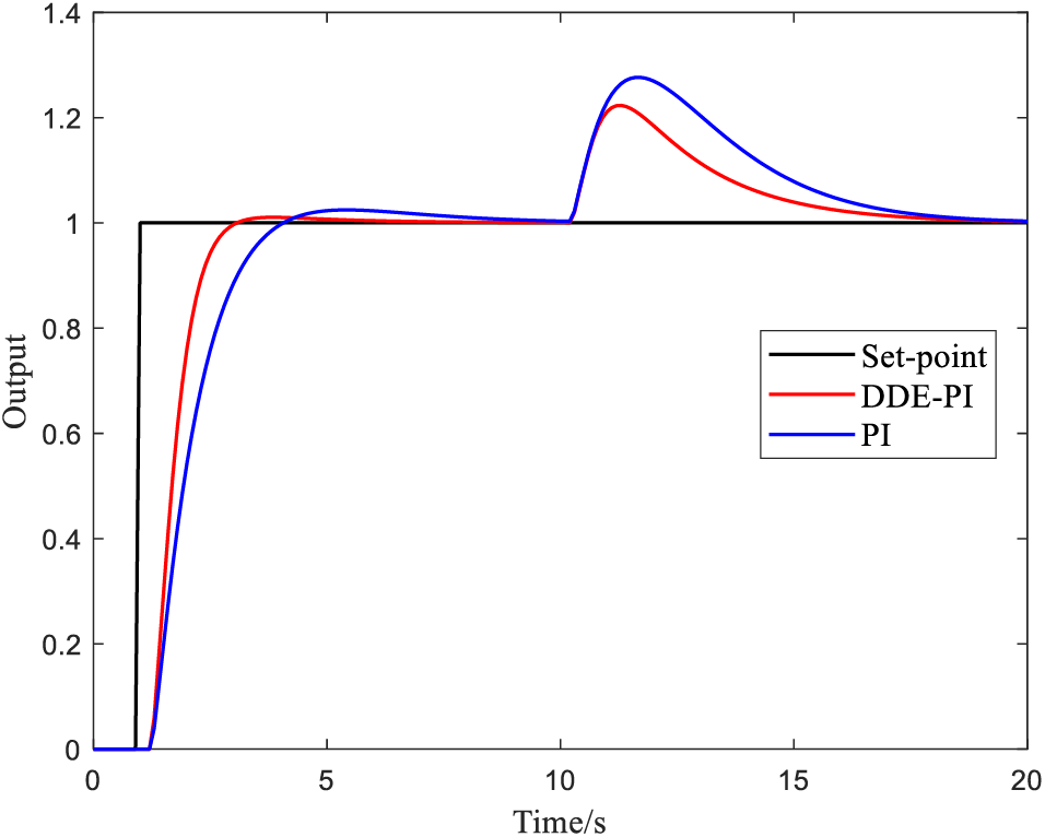
Figure 5: The control performance of DDE-PI for
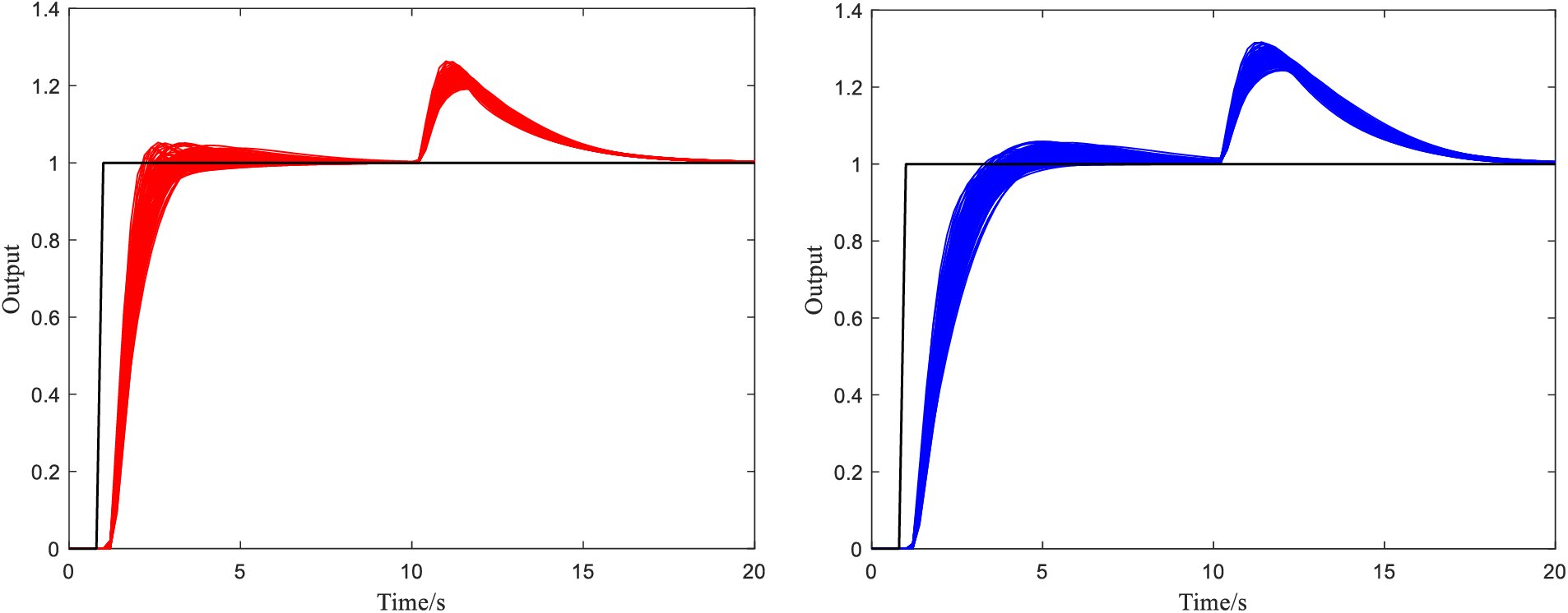
Figure 6: The control performance of DDE-PI and PI for uncertain systems (Left: DDE-PI, Right: PI)
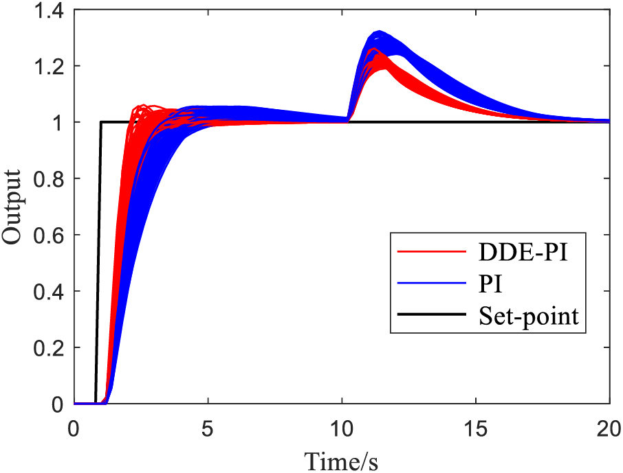
Figure 7: The control performance of DDE-PI and PI for uncertain systems in one figure
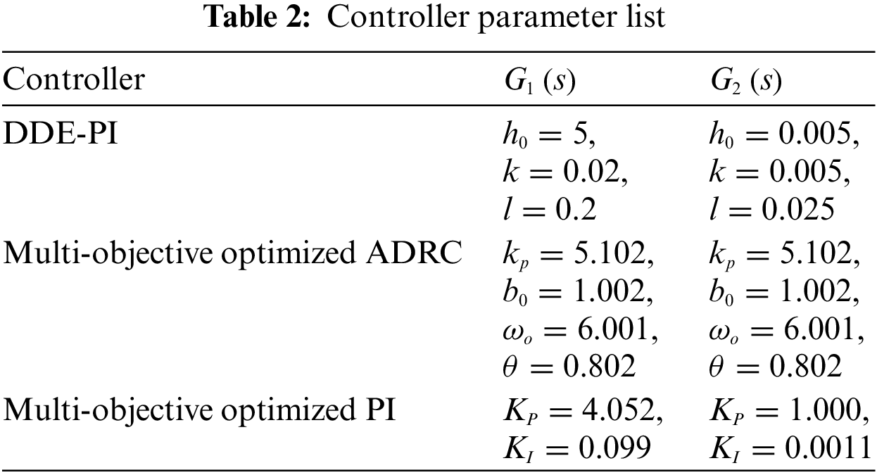
The DDE-PI controller proposed in this section will be applied to the gas turbine PFM system shown in Fig. 1, both
5.1 Control Performance Comparison under Nominal Working Conditions
Under nominal working conditions, i.e., the model parameters are the nominal parameters given in Section 2, the simulation results are obtained and shown in Figs. 8 and 9, the simulation settings are as follows: Under initial stable working conditions of the system, the PFM signal of the unit steps up at 100 s, that is at 100 s it rises by 0.0025 and then stabilizes; At 600 s, it rises again by 0.0025 and then stabilizes; At 1100 s, the speed drops by 0.0050 and then stabilizes. Note that the model established in Fig. 1 is in the form of a unit system, the value is 1 under nominal working conditions, and the values of parameters change on this basis.
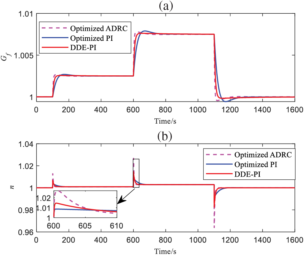
Figure 8: Outputs of
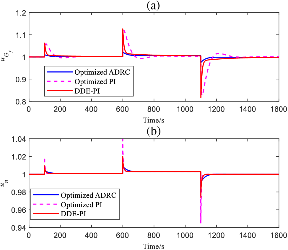
Figure 9:
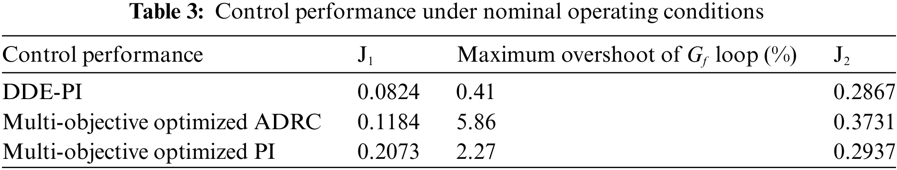
From Fig. 8a, the DDE-PI proposed in this study has the minimum overshoot, faster response than multi-objective optimized PI, and its response speed is very close to that of multi-objective optimized ADRC. From Fig. 8b, the overshoot of DDE-PI is smaller than that of multi-objective optimized ADRC, and only slightly larger than that of multi-objective optimized PI. However, the response speed of DDE-PI is much faster than that of multi-objective optimized PI. To better measure the control performance of three control strategies, define the following indexes:
where
5.2 Control Performance Comparison under Uncertain Operating Conditions
Due to the change of dynamic parameters of the gas turbine model with working conditions, modeling simplification and other reasons, the system would have some uncertainties [20]. To measure the control performance of the above control strategies in the presence of system uncertainty, some dynamic parameters from
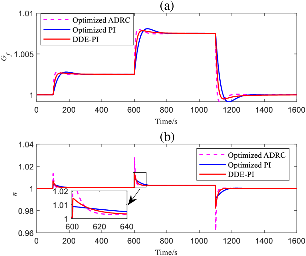
Figure 10: Outputs of
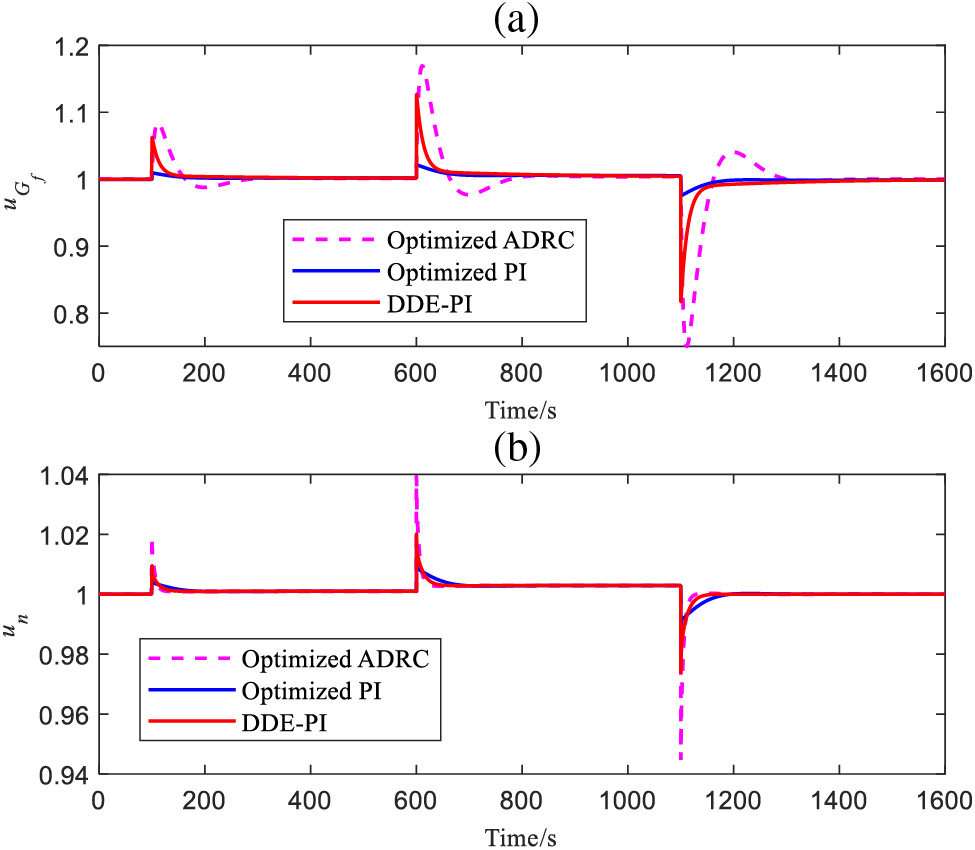
Figure 11:
To further compare the ability of control strategies to cope with the uncertainty of PFM systems, firstly, the dynamic parameters of the gas turbine,
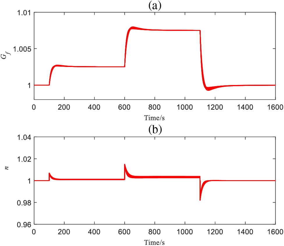
Figure 12: Outputs of
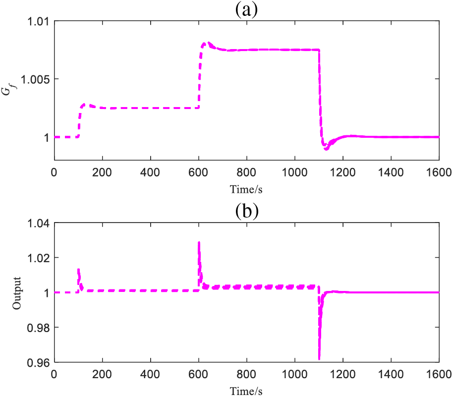
Figure 13: Outputs of
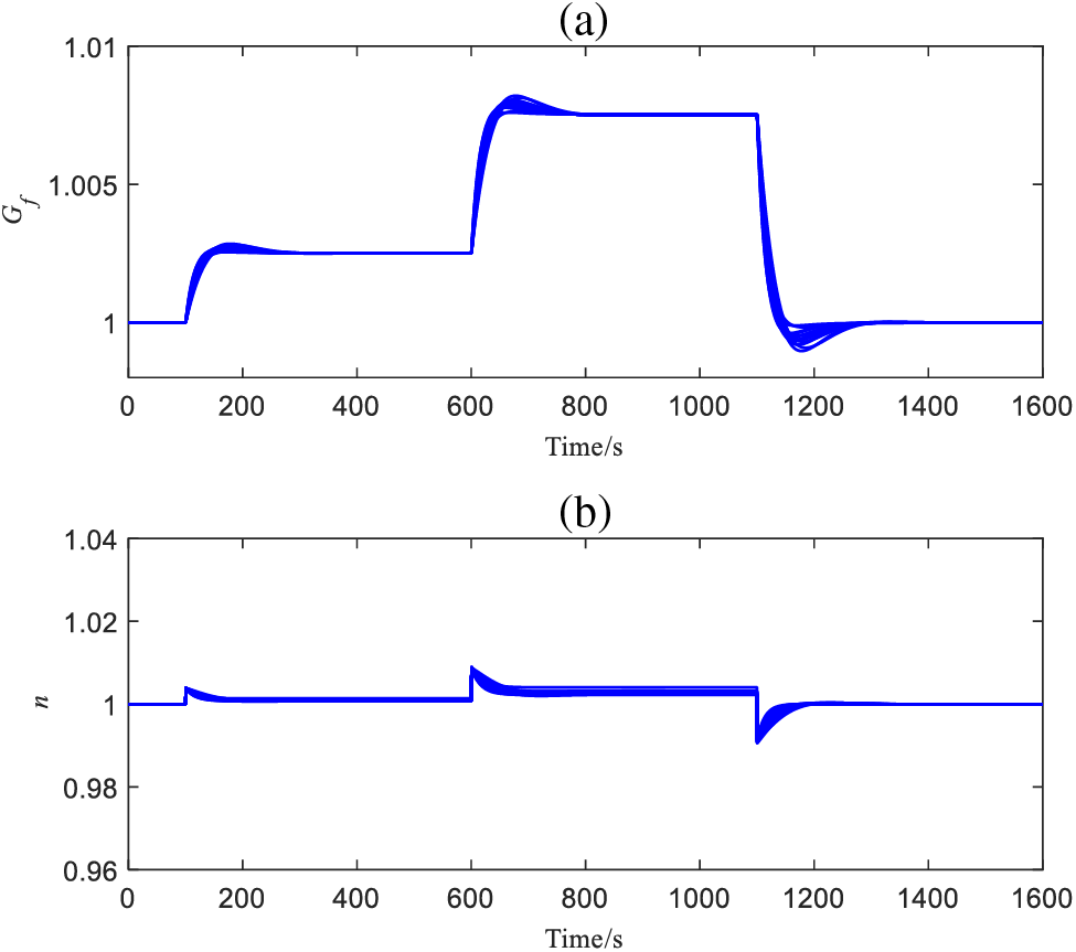
Figure 14: Outputs of
From Figs. 12–14, DDE-PI can ensure that the MS6001B heavy-duty gas turbine PFM system maintains a relatively ideal control performance even in the presence of uncertainty, the output results of
In order to improve the PFM capability of gas turbines, a DDE-PI controller is proposed in this study to enhance the control performance of the PFM system. Firstly, a typical PFM model of an MS6001B heavy-duty gas turbine is introduced, and its control characteristics are analyzed. Next, the DDE-PI control strategy is introduced, and an easy-to-implement and highly engineered parameter tuning procedure is summarized. Finally, the DDE-PI control method is applied to the PFM system of an MS6001B heavy-duty gas turbine, the simulation results show that the DDE-PI control strategy can achieve smaller overshoot with a fast response, demonstrating strong engineering application value. Based on the theoretical and simulation analysis, the subsequent work will further validate the effectiveness of the proposed method by completing the on-site realization of control logic, logical protection, parameter tuning, and putting into operation on-site of DDE-PI for actual units.
Acknowledgement: We would like to thank all those who have contributed to this paper for their valuable assistance, and thanks for the support provided by Jiangsu Frontier Electric Technology Co., Ltd.
Funding Statement: This work is supported by Science and Technology Project of Jiangsu Frontier Electric Technology Co., Ltd. (Grant Number KJ202004), Gao A. M. (author who received the grant).
Author Contributions: The authors confirm their contribution to the paper as follows: study conception and design: Aimin Gao, Xiaobo Cui; data collection: Guoqiang Yu; simulation verification: Xiaobo Cui; analysis and interpretation of results: Aimin Gao, Jianjun Shu, Tianhai Zhang; draft manuscript preparation: Aimin Gao, Xiaobo Cui. All authors reviewed the results and approved the final version of the manuscript.
Availability of Data and Materials: The data that support the findings of this study are available from the corresponding author, upon reasonable request.
Conflicts of Interest: The authors declare that they have no conflicts of interest to report regarding the present study.
References
1. Ji, G. J., Jiang, Y. (2020). Optimization of primary frequency control strategy for gas turbines. Thermal Turbine, 49(4), 262–266. [Google Scholar]
2. Wu, H. B. (2012). Primary frequency regulation based optimization for control system of M701F gas-steam combined cycle power unit. Thermal Power Generation, 41(12), 61–64+67. [Google Scholar]
3. Xi, X. G., Sun, W. (2021). The optimization of primary frequency modulation on 9E gas turbine. Gas Turbine Technology, 34(3), 50–52+72. [Google Scholar]
4. Xiao, X. Y., Shi, Y. Y., Tang, K. Y., Gao, A. M., Zhang, T. H. (2022). Analysis and optimization on primary frequency control of an Ansaldo AE94.3A gas turbine. Power Equipment, 36(1), 71–74. [Google Scholar]
5. Wang, C., Liu, S. M. (2006). Simulation and discussion on primary frequency regulation of gas turbine. Thermal Turbine, 1, 23–26. [Google Scholar]
6. Chen, J. Q., Ma, D., Xu, Y., Chen, J. (2022). Delay robustness of PID control of second-order systems: Pseudo-concavity, exact delay margin, and performance trade-off. IEEE Transactions on Automatic Control, 67(3), 1194–1209. [Google Scholar]
7. Shu, J. J., Cui, X. B., Yu, G. Q., Gao, A. M., Shi, Y. Y. et al. (2022). Active disturbance rejection control based on multi objective genetic algorithm for primary frequency modulation. Science Technology and Engineering, 22(3), 1068–1075. [Google Scholar]
8. Deng, Q. C., Liu, S. M., Sun, H. (2015). Effect of gas turbine feed forward neural networks on primary frequency regulation. Thermal Turbine, 44(2), 127–132. [Google Scholar]
9. Du, S. L., Zhang, Q. D., Cao, B. Q., Qiao, J. F. (2022). A review of model predictive control for urban wastewater treatment process. Information and Control, 51(1), 41–53. [Google Scholar]
10. Cheng, T., Zeng, Z. Z., Du, X. F., Wang, F. Q., Cheng, Q. Z. (2019). Predictive self-coupling PI control method for large time-delay systems. Information and Control, 48(6), 672–677. [Google Scholar]
11. Wang, W. J., Li, D. H., Gao, Q. R., Wang, C. F. (2008). A two degree-of-freedom PID controller tuning method. Journal of Tsinghua University (Science and Technology), 11, 1786–1790. [Google Scholar]
12. Xue, Y., Li, D., Liu, J. (2010). DDE-based PI controller and its application to gasifier systems temperature control. International Conference on Control, Automation and Systems, pp. 2194–2197. Gyeonggi-do, Korea. [Google Scholar]
13. Shi, G. J., Liu, S. J., Li, D. H., Ding, Y. J., Chen, Y. Q. (2022). A controller synthesis method to achieve independent reference tracking performance and disturbance rejection performance. ACS Omega, 7(18), 16164–16186. [Google Scholar] [PubMed]
14. Liu, S. M., Wang, C. (2004). Analysis and discussion on primary frequency regulation of gas turbine and combined cycle. Thermal Turbine, 33(3), 154–157. [Google Scholar]
15. Tornambe, A. (1994). A decentralized controller for the robust stabilization of a class of MIMO dynamical systems. Journal of Dynamic Systems, Measurement, and Control, 116, 293–304. [Google Scholar]
16. Somefun, O. A., Akingbade, K., Dahunsi, F. (2021). The dilemma of PID tuning. Annual Reviews in Control, 52, 65–74. [Google Scholar]
17. N.'Doye, I., Asiri, S., Aloufi, A., Al-Awan, A., Laleg-Kirati, T. (2020). Intelligent proportional-integral-derivative control-based modulating functions for laser beam pointing and stabilization. IEEE Transactions on Control Systems Technology, 28(3), 1001–1008. [Google Scholar]
18. Shafiei, Z., Shenton, A. T. (1994). Tuning of PID-type controllers for stable and unstable systems with time delay. Automatica, 30(10), 1609–1615. [Google Scholar]
19. Xiang, S. W., Fan, H. Q., Fu, Q. (2021). Error distribution of zero-effort miss distance under mode mismatch. International Journal of Control, 94(3), 643–652. [Google Scholar]
20. Wu, Z. L., Li, D. H., Chen, Y. Q. (2020). Active disturbance rejection control design based on probabilistic robustness for uncertain systems. Industrial & Engineering Chemistry Research, 59(40), 18070–18087. [Google Scholar]
Cite This Article
 Copyright © 2024 The Author(s). Published by Tech Science Press.
This work is licensed under a Creative Commons Attribution 4.0 International License , which permits unrestricted use, distribution, and reproduction in any medium, provided the original work is properly cited.
 Downloads
 Citation Tools