
 Submit a Paper
 Propose a Special lssue
 Open Access
ARTICLE

Numerical Analysis of the Influence of Liquid Cooling Flow Space on the Assessment of Thermal Management of PEMFC
1 College of Energy Engineering, Zhejiang University, Hangzhou, 310027, China
2 College of Agriculture and Environmental Science, Kaduna State University, Kaduna, 800283, Nigeria
3 Longquan Industrial Innovation Research Institute, Longquan, 323700, China
4 Provincial Key Laboratory of New Energy Vehicles Thermal Management, Longquan, 323700, China
* Corresponding Author: Shusheng Xiong. Email:
Energy Engineering 2025, 122(3), 1025-1051. https://doi.org/10.32604/ee.2025.057680
Received 24 August 2024; Accepted 12 December 2024; Issue published 07 March 2025
 View Full Text
 Download PDF
Abstract
This study uses numerical simulations of liquid cooling flow fields to investigate polymer exchange membrane fuel cell (PEMFC) thermal control. The research shows that the optimum cooling channel design significantly reduces the fuel cell’s temperature differential, improving overall efficiency. Specifically, the simulations show a reduction in the maximum temperature by up to 15% compared to traditional designs. Additionally, according to analysis, the Nusselt number rises by 20% with the implementation of serpentine flow patterns, leading to enhanced heat transfer rates. The findings demonstrate that effective cooling strategies can lead to a 10% increase in fuel cell performance under varying operational conditions, including pressures of 2 bar and relative humidity levels of 30%, 60%, and 80%. These results underscore the importance of cooling flow design in optimizing PEMFC performance.Keywords
Nomenclature
| Flows cross-section area | |
| CFD | Computational fluid dynamics |
| DOE | Design of experiment |
| FVM | Finite volume method |
| HT-PEMFC | High-temperature proton membrane exchange fuel cell |
| PEMFC | Proton exchange membrane fuel cell |
| MEA | Membrane electrode assembly |
| RH | Relative humidity |
| FVM | Finite volume method |
| Nusselt number | |
| Span-wise | |
| Normal | |
| Stream-wise | |
| Specific heat (J kg−1 K−1) | |
| Specific heat of water (J kg−1 K−1) | |
| Hydraulic diameter (mm) | |
| Channel depth (mm) | |
| Frictional factor | |
| Dimension (mm) | |
| Thermal conductivity (Wm−1 K−1) | |
| Thermal conductivity of water (Wm−1 K−1) | |
| Fluid corresponds | |
| Solid corresponds | |
| Pressure drops | |
| P | Wetted perimeter |
| Heat flux (Wm−2) | |
| Channel length (mm) | |
| Average interfacial temperature (°C) | |
| Average surface temperature (°C) | |
| Temperature uniformity index (°C) | |
| Maximum temperature (°C) | |
| Minimum temperature (°C) | |
| Tw | Inlet fluid temperature (°C) |
| Density of plate (Pa s) | |
| The density of water (Pa s) | |
| Rib width (mm) | |
| Velocity component (m/s) | |
| Viscosity of water (Pa s) | |
| Density and dynamic viscosity (Pa s) |
The increasing concerns about environmental contamination have led to a global search for new and cutting-edge energy sources and the crisis in energy [1,2]. In the last few decades, a number of fuel cells have been considered a viable substitute for internal combustion engines (ICEs), and have been the subject of numerous energy-related studies, featuring no moving mechanical parts and a high efficiency and power density (up to 58% for PEMFCs) [3,4]. Fuel cells represent a promising advancement in green energy technology, which provides a reliable and efficient substitute for traditional energy sources. Fuel units generate electricity with little harm to the environment by directly converting the electrochemical process to produce electrical energy from chemical Energy. Fuel cells only produce heat and water as byproducts, in contrast to conventional combustion-based power generation, which makes them an attractive option for reducing greenhouse gas emissions. Fuel cells use hydrogen or other renewable fuels to help create a sustainable energy future as part of the larger green energy scene [5,6]. PEMFCs are cutting-edge technologies that can revolutionize energy systems; their great effectiveness, advantages for the environment, and adaptability make them a promising solution for a variety of uses, including stationary power supply that is dependable and clean, as well as vehicle power. As advancements continue to address challenges related to cost, durability, and infrastructure, PEMFCs are anticipated to be crucial in the shift to a future where Energy is based on hydrogen and is sustainable.
PEMFCs are an innovative and environmentally friendly technology with significant potential in clean energy solutions. With their high efficiency, zero emissions, and versatility, PEMFCs are expected to be essential in the shift to sustainable energy sources as research continues to address cost, durability, and infrastructure challenges [7,8]. PEMFCs are expected to gain further prominence in transportation, stationary power, and portable applications. The temperature range in which a PEMFC operates is 80°C to 60°C. A considerable amount of heat is generated during the electrode reaction, and this heat accumulates and overheats the cell, lowering the efficiency of power generation. Additionally, localized hot spots quicken the PEM deterioration. As a result, the cell’s heat management is necessary.
Heat sinks, connecting pipes, coolant channels, circulation pumps, and related control devices are typically included in the thermal management system [5]. Water management and thermal management are two more crucial aspects factors PEM fuel cell performance that need to be taken into account. This is highlighted by the fact that temperature variations in fuel cells affect most of the physical characteristics of the fuel cell, like saturation pressure, species diffusivities, heat capacities, kinetic parameters, and water activity [6]. A major factor influencing the thermal management system’s performance is its coolant channel’s shape with regard to thermal management systems. In order to boost efficiency, an inventive intersectant flow path was established by Wen et al. [9], who also set up a PEMFC test system and identified the ideal operating conditions. It was discovered that the intersectant flow field’s ideal channel depth and porosity were 0.3 and 0.5 mm, respectively, in that order. The new flow field performed better than a single serpentine flow field. Guo et al. [10] created a flow field configuration that makes use of the branching structure of a tree leaf and Murray’s law.
The non-interdigitated and interdigitated configurations were contrasted with a traditional design that had a fixed channel width. The interdigitated the best-performing designs were bio-inspired. Asadi et al. [11] proposed an innovative interdigitated flow field arrangement to improve mass transfer and performance. Because the flow field repeats a wave pattern, it is known as the wave-interdigitated flow field. A three-dimensional, multi-phase computational fluid dynamics CFD model is used to simulate the fuel cell. Spiral, tapered, simple, and interdigitated flow fields that are serpentine are juxtaposed with the flow field that is wave-interdigitated. Water management research is conducted on reactant distribution and mass transfer.
Lim et al. [7] recommended effective fault diagnosis at the component level with limited data to guarantee system reliability. Heat moves through the bipolar plate from the membrane electrode to the coolant. According to Bégot et al. [8], to satisfy the PEMFC’s startup heat management requirements, a new liquid cooling circuit was developed that could raise the temperature by 26°C in 85 s. Usually, PEMFC coolants are either liquid [12] or air [13,14]. The coolant plate’s primary job is to release the waste heat from the PEMFC appropriately, guarantee a consistent temperature distribution within a specific temperature range throughout the entire active area, and stop localized overheating or undercooling from occurring. The coolant transfers heat via the coolant channel, and it usually lies in the space between the bipolar plates. Kanani et al. [15] reported that numerous factors may have a major or minor impact on how a cell functions. A few of these design specifications, as seen from an engineering perspective, are the kind of flow field, the amount of catalyst, the shape of the ribs and channels, clamping force, component thickness, and degree of hydrophilicity or hydrophobicity, etc. A number of operating conditions significantly impact PEMFC efficiency. Enhanced awareness and comprehension of these factors could lead to a rise in PEMFC efficiency.
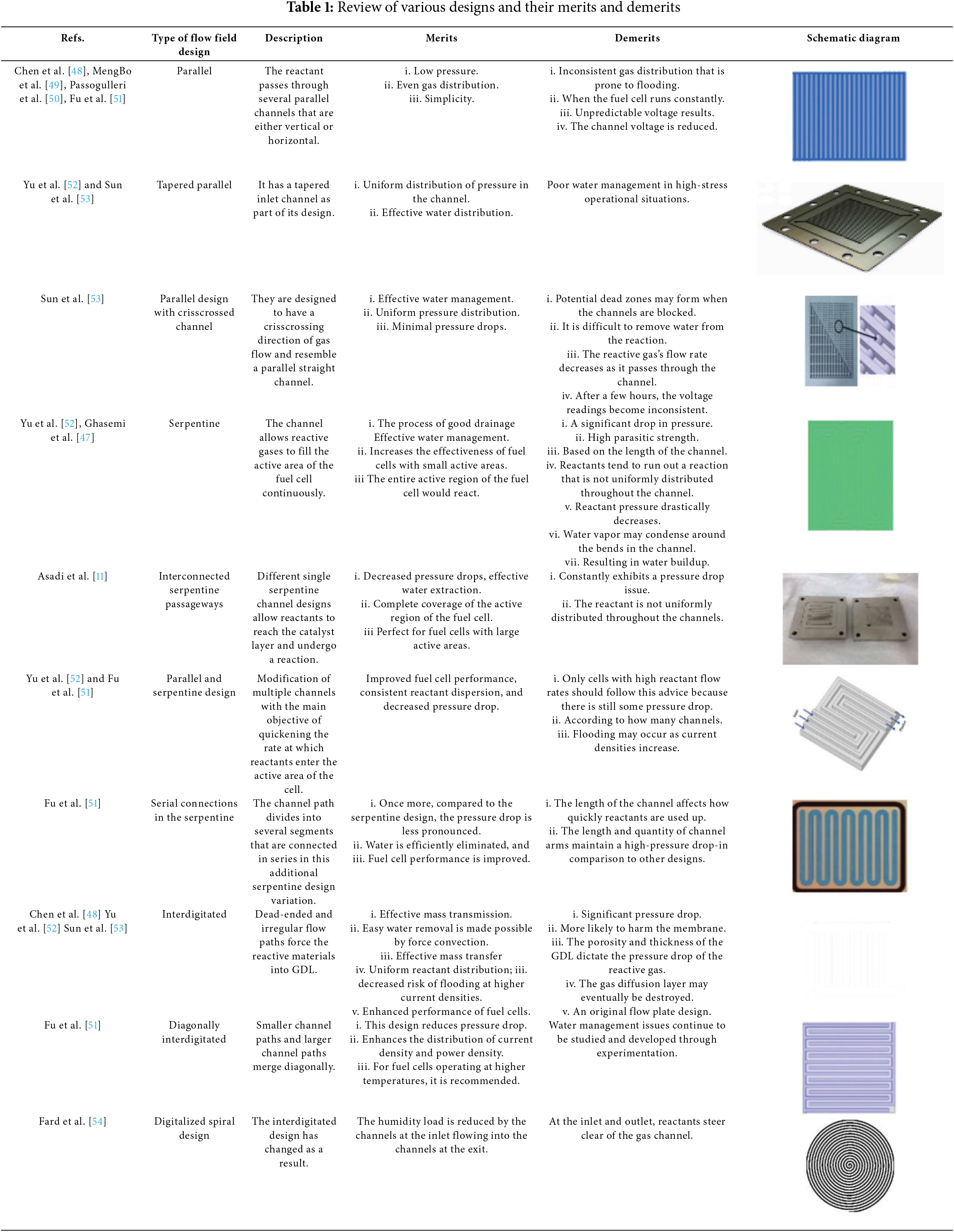
Jeon et al. [16] examined how PEMFC performance is affected by the cathode’s relative humidity in automotive applications using CFD. Wang et al. [17] established an investigation into how different flow channel configurations affect PEMFC performance optimization. The effect of changing to increase cell power and the flow field was investigated by Perng et al. [18]. The cell’s performance was 8% compared to the conventional flow channel. Ting et al. [19] replaced the traditional flow field of the PEMFC with an alloy-coated nickel foam. The conclusion they came to was that the temperature at which the cell functioned had the largest impact on its output. One of the main elements influencing the fuel cell’s temperature uniformity is lowering the water pump’s output power and increasing the fuel cell’s efficiency of flow field power generation [20]. Table 1 demonstrates how various researchers created various flow field channels and used simulation and experimentation, merit and demerit to assess the performance. Certain bipolar channels may have some utility as a cooling agent channel. Afshari et al. [21] evaluated the PEMFC’s flow fields. In recent years, researchers have compared they looked at the cooling performance of coolant channels made of different materials and flow channel shapes, and they found that each had benefits. Rather than taking into account the total system’s energy consumption, evaluation indices primarily concentrated on temperature uniformity. In the laboratory, the majority of flow field channels produced satisfactory results; however, the industrial process is costly or challenging [9].
Santarelli et al. [22] reported that six operating variables were changed by studying the behavior of a PEMFC. They gave a demonstration of how increasing Cell performance is enhanced by temperature and humidity. Additionally, they discovered that when the cell’s two sides are moistened, the working pressure is not as important. Williams et al. [23] declared that in dry conditions of operation, the performance of the anode and cathode cells is significantly impacted by the operating temperature and inlet flow rate. Temperature is another element that significantly affects the performance of fuel cells, which enhances electrode kinetics and proton conductivity through membranes for anode and cathode reactions [24]. Yet, increasing a cell’s temperature could dehydrate its membrane [25], and additional hydrogen crosses over [26]. Through experimentation, Yan et al. [27] showed that a higher cell temperature performance produces a larger cell.
They also showed that raising the temperature would result in a decrease in performance if the internal temperature of the cell is equal to or higher than the temperature at the input. The key operating conditions, such as the rate of incoming gas flow, electrode flooding, and membrane dry-out, have a significant effect on the density of current distribution [28]. Numerous experimental and numerical studies have shown that a larger cathode flow rate would enhance performance for both single cells and stacks [29,30]. For a stack of 5-kW PEMFCs, Wahdame et al. [31] created a number of full factorial experiments. They watched the effects of the current temperature and pressure. They determined the linear and nonlinear characteristics of temperature and pressure, respectively. A MATLAB–Simulink prototype for PEMFC systems was developed by Musio et al. [32] to model the performance of PEMFC stacks under various operating circumstances. They developed a steady-state PEMFC model and used experimental data to validate it. They developed a model that incorporated the PEMFC stack’s cooling mechanisms.
As was already mentioned, a variety of factors influence PEMFC performance. As a result, a thorough investigation is necessary to characterize and improve the PEMFC’s performance. The most popular method for conducting experiments is the optimization of one variable at a time; with this approach, one element changes at a different rate while the others stay the same. A similar pattern is repeated for each factor to obtain the optimal response value. Thus, a large number of experiments need to be conducted, which are ineffective, expensive, erratic, and time-consuming; numerous scientists have developed numerical models to replicate [3,5,12]. Afshari et al. [33] created two cathode flow field designs that have gained attention lately and were examined in the context of a single-channel, single-phase PEMFC model, a parallel flow field made of metal foam with a porous base and partially restricted baffles.
Kanani et al. [15] conducted experiments to determine the ideal power density and contrasted the outcomes with the prediction of the Taguchi method. Maximum produced power was predicted by Wu et al. [34] using the best possible combination of six parameters. Wu et al. [34] examined PEMFC performance in a range of operating scenarios. The comparison verified the reliability of the CFD model by demonstrating that its output was within a 5% deviation from the experimental measurements. Mahdavi et al. [35] validated a CFD model for PEMFCs with metallic bipolar plates and a cooling flow field. The model accurately predicted the A cooling flow field in PEMFCs with metallic bipolar plates within 7% of the experimental data, and it predicted temperature variations with a maximum error of 5%. The impact of cooling channel dimensions on PEMFC thermal performance is examined by Afshari et al. [36]. The temperature distribution in the numerical model deviated from the experimental results by about 6%, while the pressure drops across the channels were precisely predicted by the model and closely corresponded with the data from the experiments. Kanani et al. [37] used a validated CFD model to examine how different flow field designs impact the performance of PEMFCs. The model’s predictions were within 4% of the pressure drop across the flow fields experimental results, demonstrating high accuracy in thermal predictions. Deviations from the model’s predictions were less than 5%. Hashemi et al. [38] established a thorough CFD model for a serpentine flow field in PEMFCs and verified it using data from experiments. The predicted pressure drop was within 4% of experimental values, proving the precision of the model, and the model’s maximum error in temperature predictions was 3%, respectively.
Additionally, they demonstrated that temperature, temperatures for anode and cathode humidification, as well as cell temperature, significantly affect the performance of the flow direction cell. In the anode and cathode channels, in order to minimize pressure drops and optimize power generation, the Taguchi method was utilized by Wu et al. [39] in their single serpentine PEMFC three-dimensional model. According to their findings, when these factors are optimized together, there are 275% fewer pressure drops and 30% more power generated. Solehati et al. [40] conducted a numerical evaluation utilizing the Taguchi method to determine how operating conditions impact stack efficiency. According to their model, inlet humidification has a significant effect on stack performance and efficacy. Rao et al. [41] investigated the accumulation of water in the membrane under various operational conditions, and a model in mathematics was developed. To attain maximum efficiency without flooding, they optimized the operating parameters using the Taguchi technique. Taguchi technique employs a structured approach to experimental design, often using orthogonal arrays to efficiently explore multiple factors simultaneously. This enables researchers to evaluate how different parameters affect a system’s performance without carrying out many experiments [13]. Among the benefits of the Taguchi technique is its cost-effectiveness; lowering the number of experiments required to identify optimal conditions minimizes resource expenditure while continuing to offer insightful information about system performance [41].
Their findings demonstrated that maximum power is obtained without cathode membrane flooding at reduced cathode humidity and higher fuel cell temperature levels. To determine the parameters’ global optimum value, they additionally employed a genetic algorithm. Kanani et al. [15] created and refined a single serpentine to investigate the ways in which the operating conditions of the cell impact its capacity to generate electricity. Four key parameters are examined utilizing the experiment’s design (DOE) in order to ascertain the optimal power: the gas inlet’s temperature, relative humidity, cathode stoichiometry, and anode stoichiometry.
Zhao et al. [42] created an experimental system to verify the PEMFC thermal management system dynamic model using a numerical model of the PEMFC stack. Amirfazli et al. [43] looked into how the coolant channel dimensions and the manifold affect the stack’s uniform temperature. They found that when the manifold cross-sectional area’s incremental direction was selected, the flow direction needed to be taken into account. Liu et al. [44] determined that the stack’s optimal power performance occurred at 70°C and the least amount of temperature increase in the inlet coolant through an experimental investigation. Choi et al. [45] formulated a procedure for preheating the 5-kW high-temperature proton membrane exchange fuel cell (HT-PEMFC) equipment and carried out a number of experiments. The majority of coolant channel research is numerical, with very little being experimental. The majority of research did not test how well a PEMFC stack that has recently created a channel for coolant operated. In the meantime, many evaluation indices concentrated on temperature uniformity without taking into account the overall effectiveness of the temperature control systems within the real-world PEMFC stack. An innovative method for the creation and modeling of coolant channels, PEMFCs use the use of (CFD) to model the hydraulic and thermal behavior of coolant channels under different circumstances. Water is supplied to PEM fuel cells and transported through cooling plate channels to regulate the cells’ internal temperature. For PEM fuel cells to increase their stability, robustness, and efficiency, the ideal temperature distribution is one with little variation. According to Li et al. [46], efficient cooling is crucial for enhancing PEM fuel cell performance; thus, researchers are proposing and studying different cooling channel designs. The operational performance of a newly designed coolant channel in a PEMFC stack was not tested in the majority of studies. In the meantime, many assessment indices concentrated on temperature homogeneity without taking into account the overall effectiveness of thermal control mechanisms in the actual PEMFC stack [5]. In earlier studies, PEM fuel cells were simulated using a heat boundary under constant temperature conditions.
Furthermore, to replicate the cooling flow field, the heat generated in the PEM fuel cell was applied as a steady, uniform heat flux. Undoubtedly, in real mode, the fuel cell’s heat generation there won’t be any cooling flow field dispersed evenly [47]. Therefore, simulating PEM fuel cells while taking into account the cooling flow field’s presence aids in obtaining a cooling flow field design that is more suitable ability to cool slowly declines along the channels. Consequently, PEM fuel cells’ temperature differential between the outlet and the inlet portions rises. Enhancing the cooling channels’ downstream thermal performance is, therefore, crucial. Based on the suggested serpentine channels with a circular geometry, a single novel coolant channel is designed and simulated in this research. The heat transfer properties of the flow field in the new coolant channels at various coolant inlets flows were determined using numerical simulations, and the coolant plate’s rates and heat flow densities were identified, examined, and computed using the methodology of fluid dynamics in computation (CFD). The finite volume method (FVM) is used to solve the coupled fluid flow and heat transfer transport process. Relative humidity, temperature differential, average temperature, maximum temperature, and temperature uniformity index are used to illustrate and compare the thermal performance of the cooling channels. The primary aim is to investigate how different cooling channel designs can affect the thermal management of PEMFCs and to develop a new, user-friendly cooling fluid flow distribution design for a PEMFC stack.
The membrane electrode assembly (MEA), gas diffusion layer (GDL), and a gas diffusion layer (GDL) is located on either side of the MEA and encompasses the MEA, in addition to an oxidant. Ionization of hydrogen gas occurs at the anode, releasing electrons and producing ions of hydrogen. Oxygen interacts with the hydrogen ions in the electrolyte and the electrode’s electrons at the cathode. Electrons move from the anode to the cathode. Travel via an external electrical circuit during this process. Through the MEA, oxygen and hydrogen interact electrochemically. That generates heat. Single-unit cells make up a fuel cell stack connected in series to generate the required amount of power, as seen in Fig. 1. In order to keep the fuel cells from overheating, each cooling plate controls the heat from several unit cells and is arranged in a repeating pattern within the stack [26]. According to Fig. 1b [26], each cooling plate controls the heat from several unit cells. This study models a single cooling plate using a CFD program, as shown in Fig. 2, since it is installed between the MEA and has a circular shape. The heat flux on both sides of the cooling plate is caused by the heat generated by the electrochemical reaction between the fuel and oxidant in the MEA. Table 2 provides a comprehensive summary of the thermal and hydraulic boundary conditions.
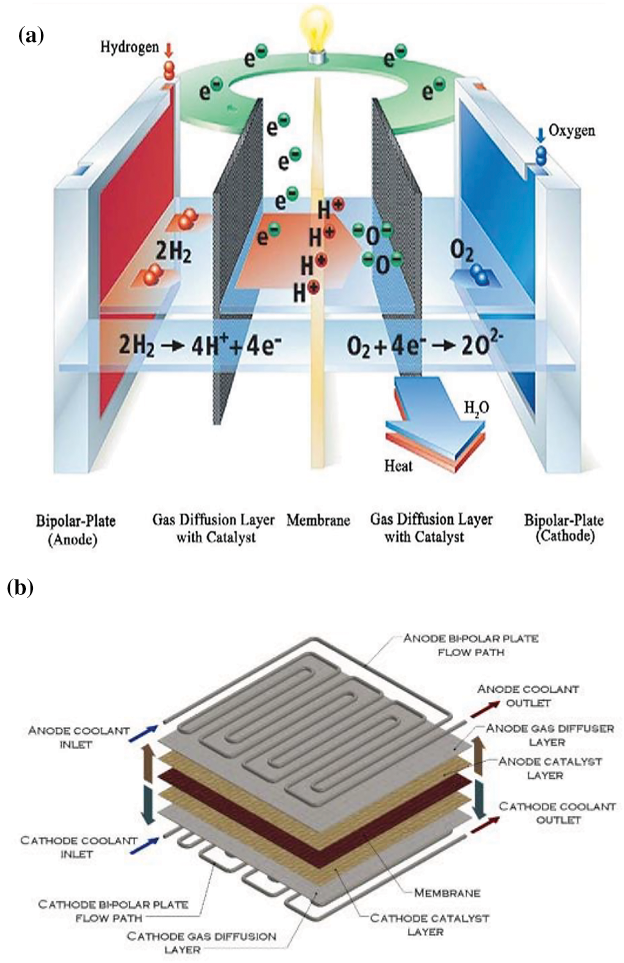
Figure 1: (a) Description of the structure of a fuel cell (b) Computational domain
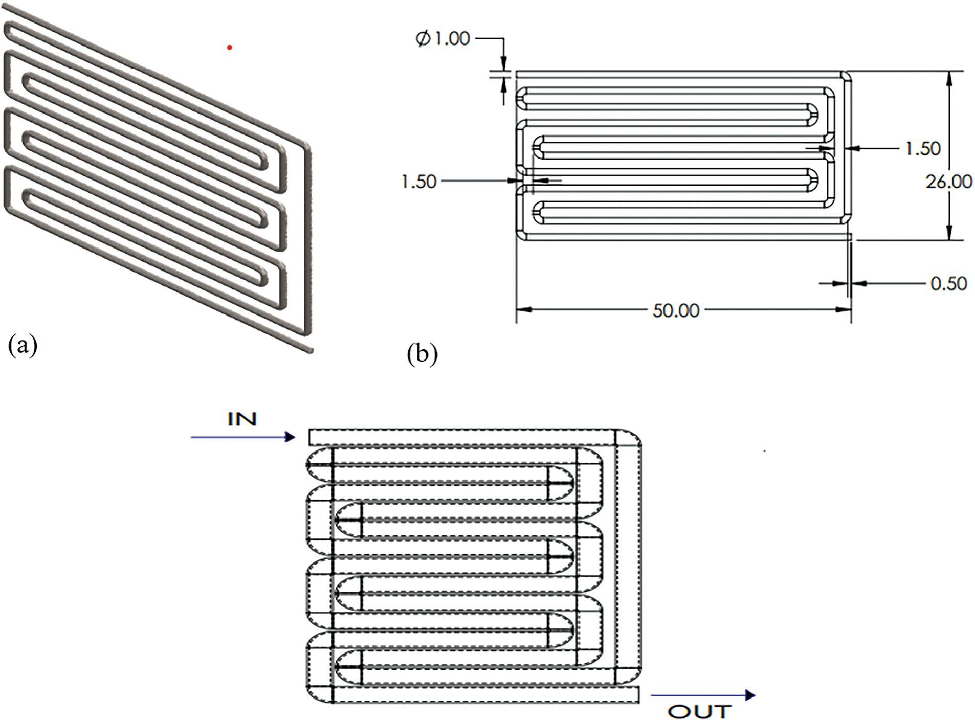
Figure 2: (a) Circular single-channel schematic diagram (b) The circular channel’s dimensions
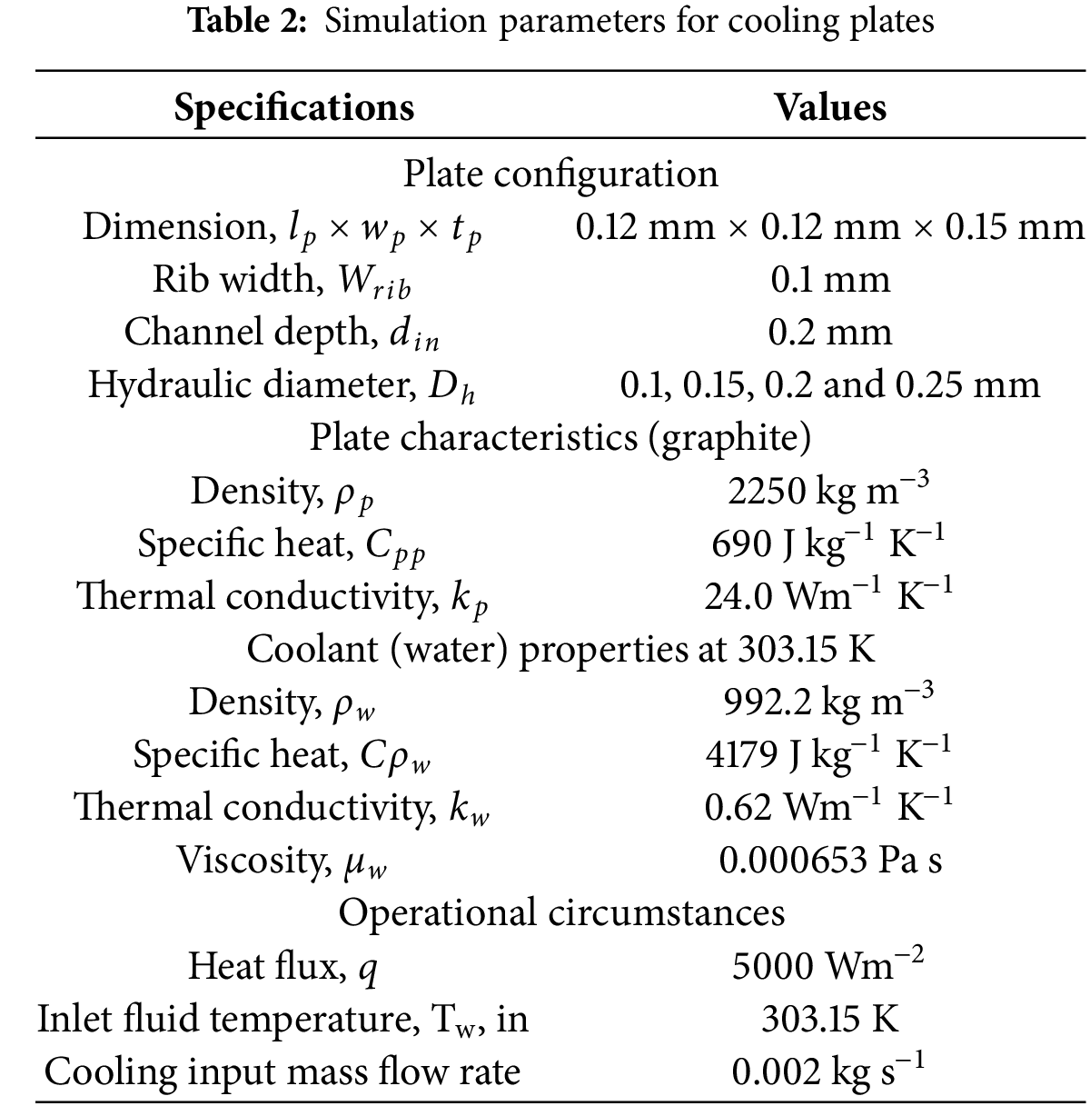
The cooling plate, made of graphite, has a cross-sectional area of 0.12 mm × 0.12 mm × 0.15 mm and a circular channel size of 0.12 mm × 0.1 mm × 0.1 mm. Its features and specifications are displayed in Table 2. As shown in Fig. 2, modified versions of popular serpentine configurations were applied to the cooling channel to achieve the thermal reliability of PEMFCs.
When water circulates through the polar plates’ internal cooling channels, the cell cools due to the heat produced inside it being transferred to the water. The water returns to a heat pump after cooling down and flowing throughout the cell’s mass. This system uses various types of equipment in addition to the cell’s mass, such as a thermostat pump, water purifier, heat exchanger, etc. A water-based cell cooling cycle is depicted in Fig. 3. With the assistance of the connected fans, the heated water that exits the fuel cell penetrates the heat source, removing the warmth generated by the fuel’s mass and lowering the cooling flow fluid temperature to the appropriate level. A controller modifies this system’s fan velocity to maintain the water’s temperature entering the cell mass (the radiator’s output) at an ideal operating point while it passes through the heating element. A subsidiary departs from the main route, takes a different branch to pass through the tank, and re-joins it. There, choking water flow measurement occurs as the cooling fluid passes through the pump and its pressure rises. Due to the need to maintain the cooling fluid’s low conductivity, an ion exchanger must separate the ions that enter the fluid and pass through it. Low fluid conductivity is necessary to prevent the cooling fluid from electrically discharging. This might result in a brief electrical contact between the mass of the fuel cells. The cooling channels’ internal design within the polar plates must meet the following requirements simultaneously.
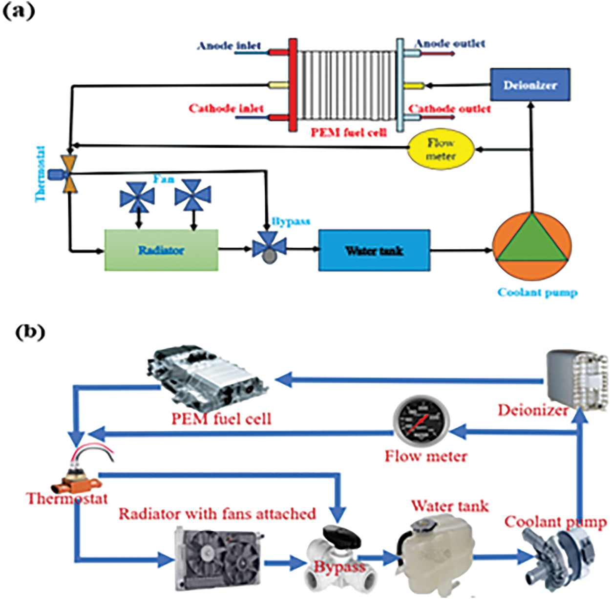
Figure 3: (a) Water-cooling mechanism layout (b) Illustration of a fuel cell cooling mechanism that makes use of PEM
i. Heat generation and removal at varying operating voltages: The cell’s mass produces heat that changes according to the amount of electrical power it produces; as the final product flow increases, this heat also increases. Because the voltage at which the cell operates can vary, at these various voltages, the cooling flow field ought to be able to eliminate heat-producing elements.
ii. The following are the minimum pressure drops in the cooling fluid to the cooling field’s direction: The heat management system’s rotating pump for cooling fluid consumes more energy as the decrease in pressure rises in the field’s direction. The fuel cell consequently generates less electrical power. Pressure drop must be minimized when designing the cooling flow field.
2.4 Numerical Details and Validation
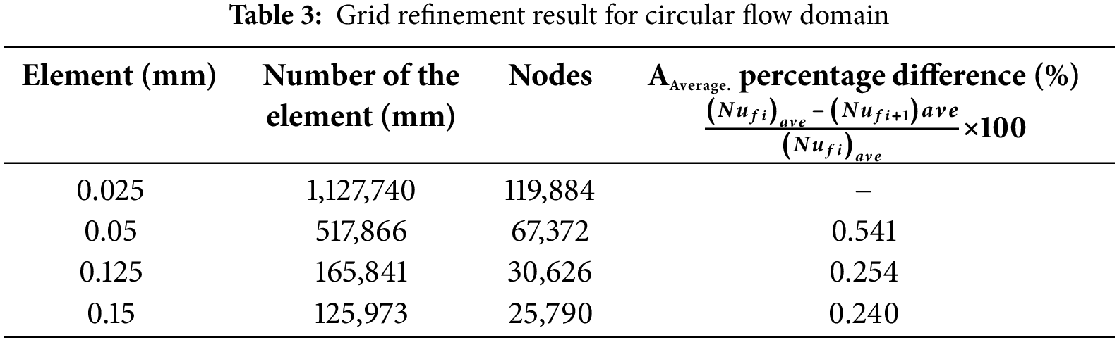
The number and type of grids strongly influence numerical simulation accuracy. The reactant gas channel schematic is shown in Fig. 1a, and Table 2 is sourced from sharif et al. [36]. It has shown that the model’s geometry and physical characteristics PEM fuel cell are gridding, which uses the traditional grid. It shows that each grid is structured and has rounded shapes (Fig. 2). For the simulation to be more accurate, the grids near the catalyst layer are smaller; where the reaction is conducted, different grids are created in order to examine the results’ grid independence. According to Fig. 4, This choice ensures the analysis’s precision and computational efficiency. The outcome demonstrated that the number of components (517,866) utilized was sufficient, and the errors ranged from 0.24% to 0.54% when increased from 1,127,740 to 517,866 and from 517,866 to 125,973, respectively.
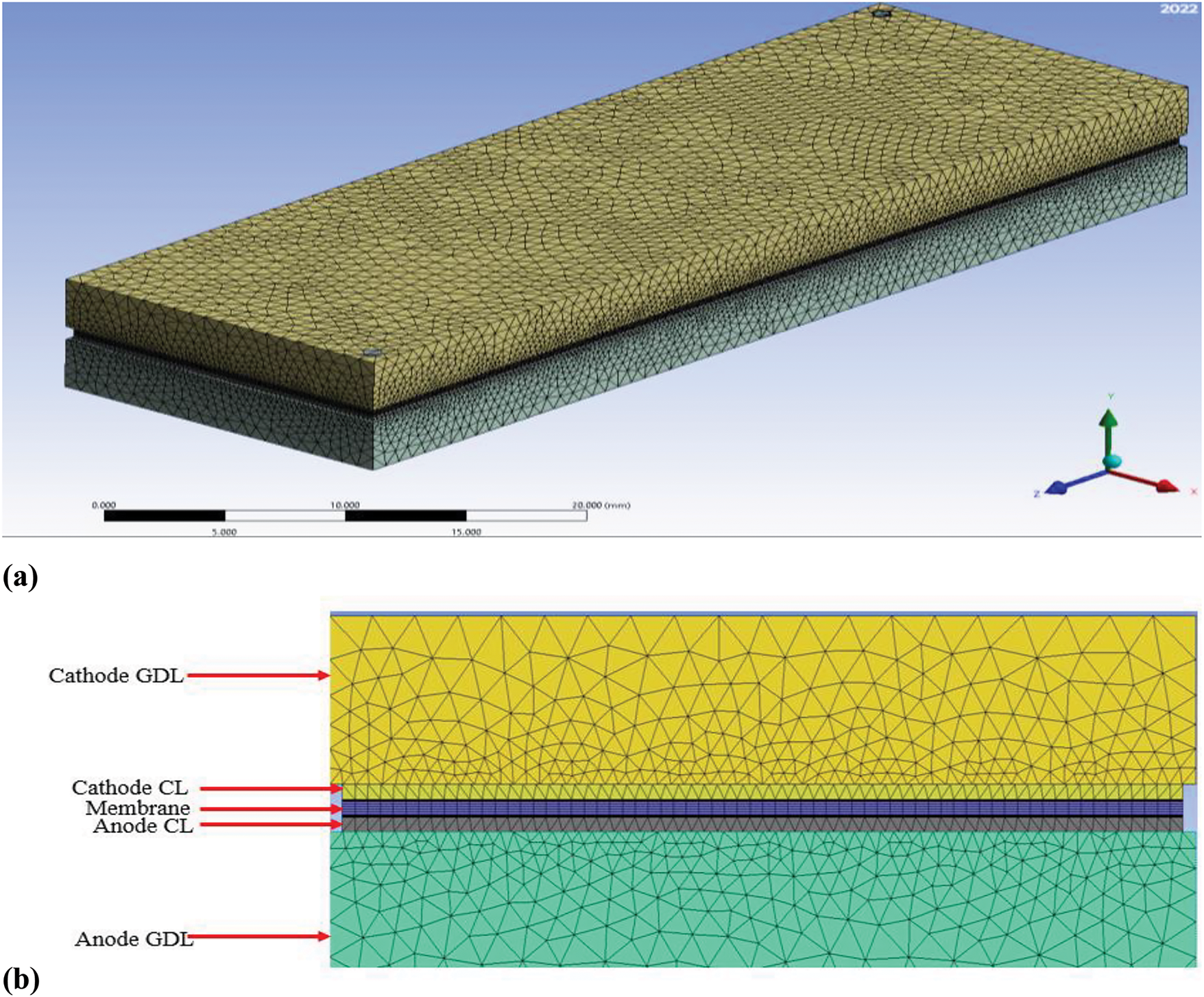
Figure 4: The field case’s mesh geometry for circular field flow: (a) An illustration in three dimensions and (b) The way that cells are arranged in different parts of the membrane electrode assembly
It is critical to evaluate grid independence, which entails selecting the proper mesh to run the simulations on. This procedure maximizes computational efficiency while improving the accuracy of numerical simulations. Ignoring network independence issues can produce unreliable outcomes, possibly resulting in incorrect analyses of these results. Because of this, tests of network independence were carried out using different mesh sizes for a single geometry, all exposed to a 60 kW/m2 heat flux, as depicted in Fig. 4. These tests’ findings show that when the mesh size grows, it certainly affects the foundation regarding the channel’s temperature. Notably, gridding the fuel cell had some issues when a cooling field was applied and cooling components concurrently due to the disparate cooling system and gas field designs; consequently, having a fairly regular grid has certain drawbacks [47]. The working fluid in the process was water in laminar flow to determine the Nusselt number, as indicated in Table 2, in accordance with the analytical findings of Refs. [26,47,54,55]. A numerical simulation was conducted for the situation of constant property water in laminar flow without a solid region in order to further validate the solution method and with a constant heat transfer over the whole wall surface.
The changes made in our study are comparable because the cooling geometry that we take into account is absent from the open sources; the geometric structure and operating parameters (heat flux, inlet temperature, and mass flow rate) were established and then verified by the conventional serpentine model “F” used in Baek et al.’s work [56]. The numerical simulation results in this paper are the lowest when compared to the references, as the figure shows when the inlet mass flow is 2 × 10⁻¹ kgs−1. The largest results, roughly 10%, are obtained from the numerical simulation at an inlet mass flow rate of 6 × 10⁻³ kgs−1. The results presented in Fig. 5 compare the pressure drop and mass flow rate of the current study with those of the study conducted by Baek et al. [56]. With 303.15 K of temperature and 30%, 60%, and 80% relative humidity, respectively, both results are in good agreement, indicating that the algorithm employed in our study is valid. The high degree of consistency between simulation results and empirical data, as shown in Table 3, indicates the dependability of the numerical model. The cooling fields examine the geometry of the study using the applied cooling field to explain the results, taking into consideration the fuel cell’s two cooling fields as well as the input gas flow fields for the anode and cathode, known as counterflow.
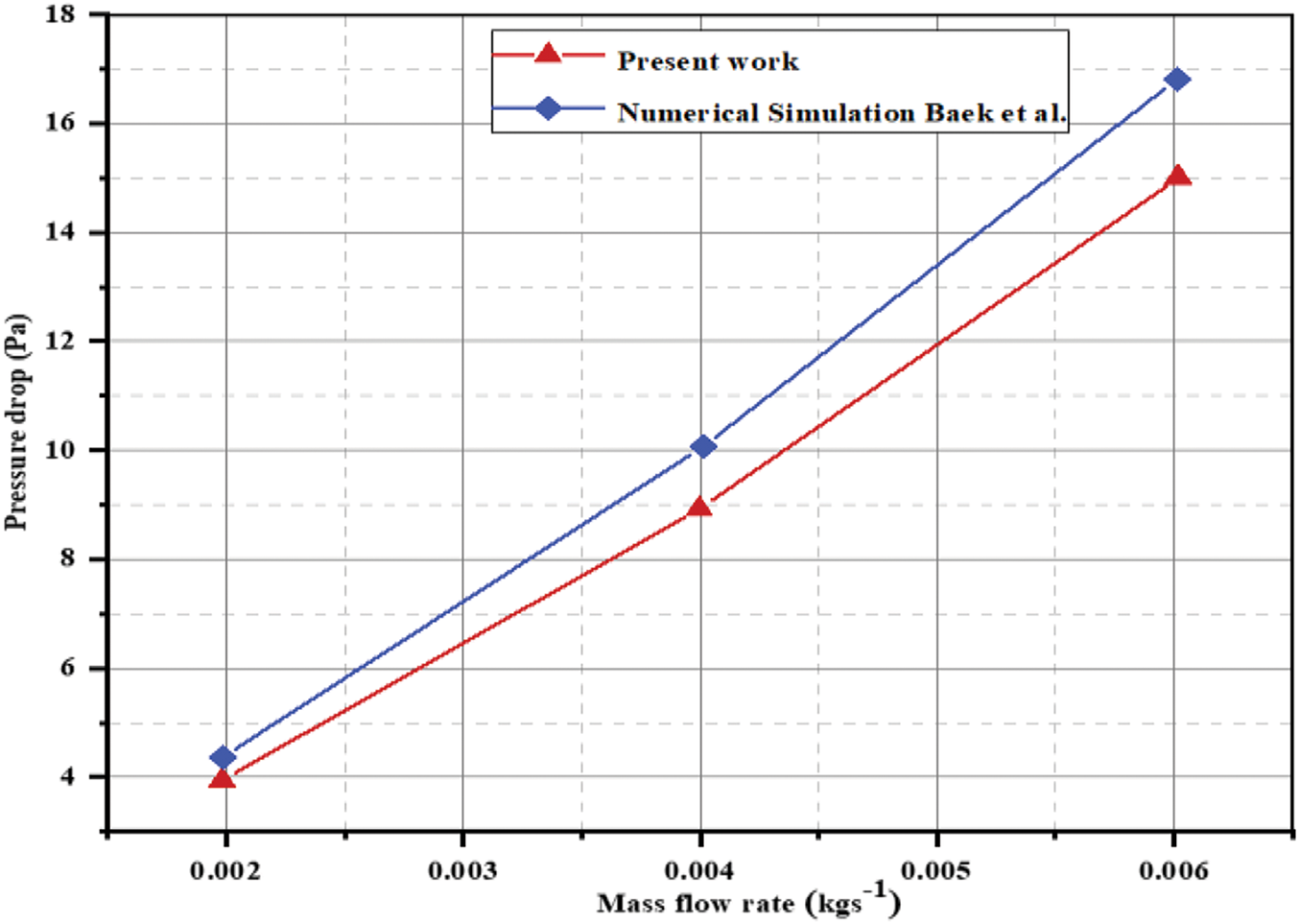
Figure 5: Pressure drops at different flow rates
Interestingly, both the cooling field input and the direction of the gas flow field are the same. The figure also displays fuel cell grids, and Fig. 4 shows a slice of the fuel cell from the front. Analysis is done on the remaining Disparities between the model and the experimental data predictions. In the study, it was noted that the maximum error in temperature predictions was less than 5%, which further supports the model’s validity. Following that, the numerical results are contrasted with additional information from the literature, such as that was published by Sharif et al. [36], Khoshvaght-Aliabadi et al. [55] for the Nusselt number, and Afshari et al. [57] for the friction factor to confirm the validity of the current investigation. The current findings closely resemble those of other researchers, as shown in Fig. 6. This comparison has validated the procedure used in this study. As a result, the findings in the following section are trustworthy and debatable.
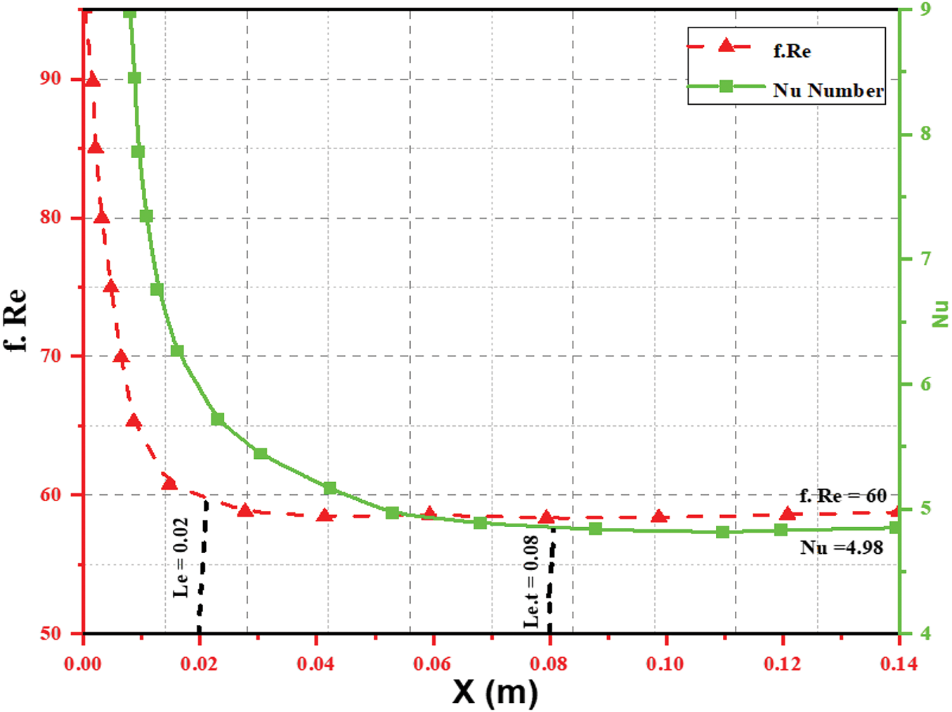
Figure 6: Analysis of the cross-channel Reynolds number (f. Re). In a straight channel, the friction coefficient of Darcy and Nusselt number with a 2-aspect ratio
Analytical and numerical techniques are the traditional means of forecasting and calculating the forces applied to objects that come into contact with the flowing fluid. As the analytical techniques are applicable to simple geometries, complex flows are not a good fit for them. The most accurate approach is to use experimental methods. However, experimental tests are not worth the laboratory equipment is expensive and requires a large initial investment, particularly if multiple tests are required. Making use of a numerical approach can result in a significant cost reduction [7–9]. In a numerical method, the inner nodes of each cell solve a fluid flow problem (temperature, pressure, velocity, etc.). Typically, a numerical problem’s accuracy is more important than a network’s cell count. The finite volume method (FVM) is used in our project to solve the equations.
Using AutoCAD, the fluid domain model was produced to be solved using Fluent software’s PEMFC module. The configuration method was designed to be integrated with Fluent, and the internal heat-fluid model’s configuration technique was created to work with Fluent. The simulation’s computational domain consists of the bipolar PEM, an anode and cathode catalyst layer, and the cathode diffusion layer, an anode, a flow channel, and plates. Table 2 displays the geometrical and operating parameters. The temperature at the inlet, species concentration, and mass flux must be set during the solving process. The pressure outlet served as the outlet’s boundary conditions. For a fixed wall, the species flux is zero. It was believed that the temperature would remain constant. Discretization of the nonlinear and coupled equation initially, followed by an iteration using the SIMPLE algorithm [26]. When two iterations’ relative errors are less than, the model-solving process tends to converge
The PEM fuel cell’s physical operations are typically represented mathematically through the solution of the conservation equations for charge, mass, momentum, energy, and chemical species. For water vapor, chemical species conservation equations account for the gas phase, and the saturated model is used to determine the liquid water volume fraction. These are the governing equations, expressed as [57,58]:
(a) Continuity equation
Furthermore, using the relationship given by [55], equations for the fluid’s continuity, momentum, and energy.
(b) Momentum equation
(c) Energy equation
The subscripts
Conversely,
The wetted perimeter is denoted by p in the equation, and the dry perimeter by
The equation provided by (9) can be used to calculate the thermal resistance as follows:
where
Furthermore, using Eq. (12) by [43],
Table 4 provides a comprehensive summary of the thermal and hydraulic boundary conditions.
The formula provides the value of the pressure drop [54,60]:
The pumping power can be computed using the formula below:
where
Research on the Nusselt and Darcy friction factors figure regarding a simple pathway channel was compared alongside the analysis outcomes to verify the numerical model. Fig. 6 displays the parameter values along the circular channel, such as friction coefficients and Nusselt numbers.
The hydraulic and thermal entrance lengths are ascertained empirically when the Reynolds number is 330. These parameters yielded values of 0.02 and 0.08, respectively. A circular channel with a two-aspect ratio and a fully developed laminar flow has f. Re and Nu numbers rapidly approach 60 and 4.98 after the entrance length. These values agree well with the 61 and 4.12 reference values [36,57]. Two cases have been studied to determine how the depth and width of the channels’ cross-sectional dimensions affect cooling efficiency. Under changing channel depth that remains constant and wide, an analysis has been conducted on the functioning of a circular-shaped direct serpentine cooling flow field. The cooling plate’s length, width, and distance between the channels have remained constant in both cases. Table 2 displays the cooling plate measurements for the primary field, which form the basis for comparison. The cooling plate surface’s maximum temperature needs to be maintained at the predetermined level in order to guarantee the cell’s thermal stability. Therefore, the most important element in avoiding heat damage to the temperature of the cell surface. To more accurately compare cooling performance, the temperature uniformity index was also calculated using the relationship described by [47,54,57].
The heat transfer’s average surface temperature on the cooling plate is called Tavg, with T representing the surface temperature. The temperature uniformity index calculates the departure from the heat transfer surface’s average temperature. Put differently, UT has a zero value for an exact distribution of temperatures. The degree of heat distribution in Fig. 6 is depicted on the cooling plate’s central surface, measuring 0.12 mm × 0.12 mm (a symmetrical boundary) and a channel measuring 0.15 mm across and 0.1 mm deep. The liquid temperature rises due to heat absorption by the cell along the channel length, peaking at the channel ends. The cooling plates effectively dissipate reaction heat, preventing overheating and maintaining a steady temperature across the active cell surface. The findings in [18] align with this observation.
Temperature distributions across membranes in proton exchange PEMFCs or membrane fuel cells at different relative humidity (RH) levels are displayed in Fig. 7. According to the figure when the relative humidity rises, the maximum temperature within the membrane also rises. The higher rates of electrochemical reactions explain this phenomenon and the proton migration that happens when the membrane is properly hydrated. Higher humidity levels facilitate better ionic conductivity, which is crucial for the performance of PEMFCs Yan et al. [25] and Chen et al. [26]. At lower RH levels, such as 30%, the temperature gradient across the membrane is more significant. This steep gradient can lead to thermal stress, which may adversely affect the membrane’s integrity and performance. The increased thermal stress at low humidity can result in localized overheating, potentially leading to membrane degradation [17,22].
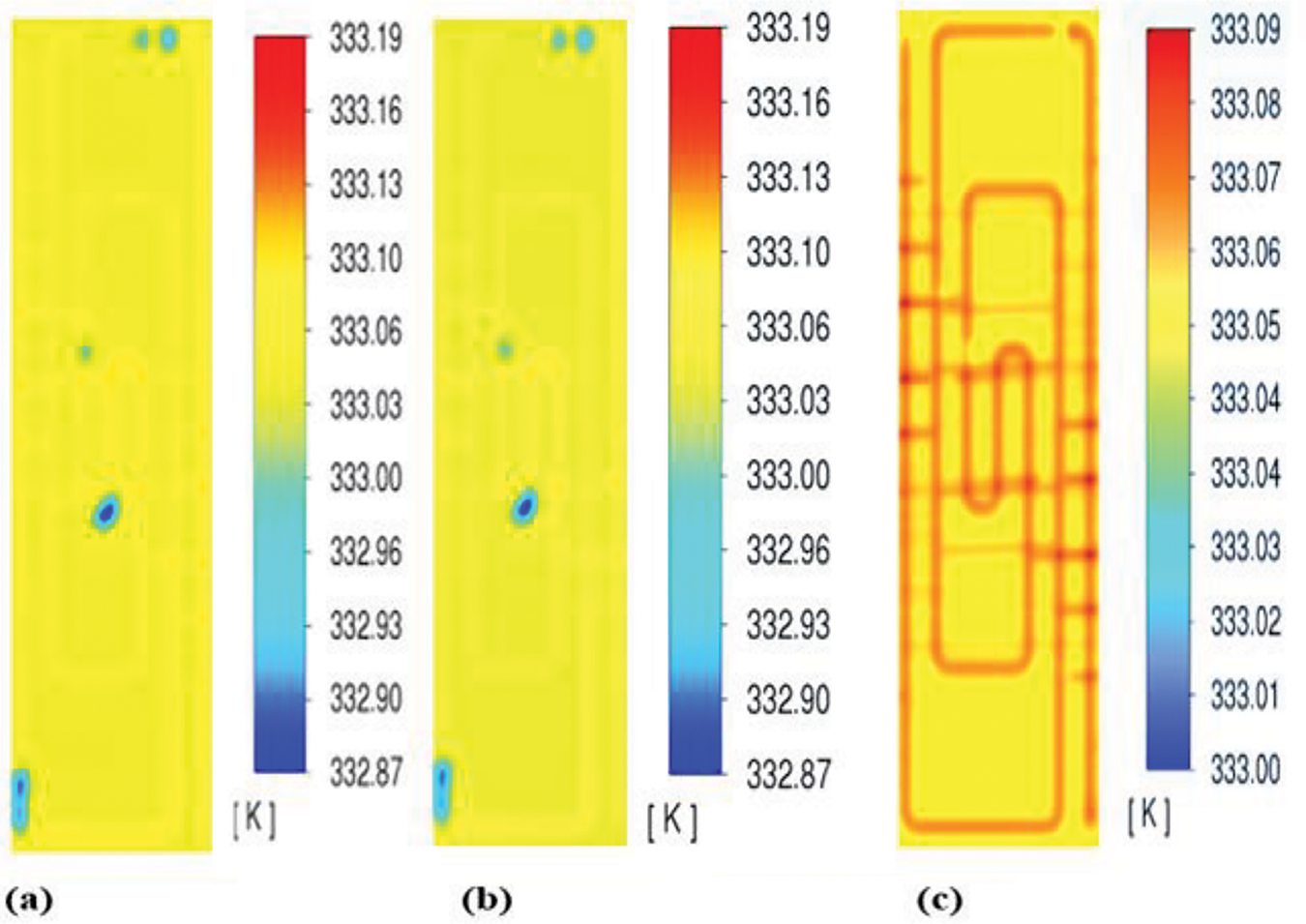
Figure 7: Distribution of temperature in the membrane when RH is 30%, 60% and 80%, respectively
According to the data, a more uniform temperature distribution is produced at an ideal relative humidity level of roughly 60%. This homogeneity helps to sustain steady electrochemical reactions throughout the membrane, which improves the fuel cell’s overall performance. A balanced humidity level helps prevent issues such as flooding or drying out of the membrane, which can significantly impact fuel cell efficiency [16,20]. The findings from Fig. 6 highlight the importance of effective thermal management strategies in PEMFC design. To maximize fuel cell performance, engineers need to take the interaction of temperature and humidity into account. The PEMFC can function effectively under a variety of load circumstances by maintaining ideal operating conditions with the aid of sophisticated cooling systems and dynamic thermal management [21,32].
Furthermore, it emphasizes how crucial the connection is between membrane temperature and relative humidity in PEMFCs. Understanding this relationship is essential for optimizing fuel cell design and operation, as it directly influences performance and durability. Future research can be guided by the knowledge gathered from this analysis and research and development initiatives meant to raise PEMFC systems’ efficiency [19].
Additionally, Fig. 7a–c shows the distribution of temperature in the membrane as a function of relative humidity at 30%, 60%, and 80%. A significant temperature gradient occurs at 30% relative humidity, and the internal membrane temperature may peak at 335.07 K, indicating high thermal stress that may compromise membrane integrity. The temperature distribution becomes more consistent at 60% relative humidity, and the highest temperature drops to about 333.19 K. This value improves the electrochemical reaction's stability and the fuel cell's overall performance; compared to lower values, a 10% increase in efficiency can be observed [47,53]. A peak temperature of 335.15 K is caused by a high humidity of 80% RH. Although this suggests increased ionic conductivity, it can also result in flooding, where performance may be harmed by an excess of water in the membrane.
This study illustrates how determining the right relative humidity is essential to creating efficient thermal management plans for PEMFC. By closely examining the effects of temperature and humidity on membrane performance, this work expands on earlier research and emphasizes the need for these parameters to be taken into account in future fuel cell engineering design [47,53]. According to the research, a consistent temperature distribution reduces localized overheating, so sophisticated cooling systems are essential for maximizing fuel cell efficiency in both design and implementation. Findings will make it possible to conduct additional research by investigating novel coolant channel designs and operational tactics that can dynamically adjust to shifting circumstances, enhancing PEMFC technologies' longevity and efficiency. In order to meet the world's energy needs, engineers are urged to focus more on temperature and humidity control in their future designs. This could result in fuel cell systems that are more efficient and sustainable.
Proton Exchange Membrane Fuel Cells (PEMFCs) at varying relative humidity (RH) levels are shown in Fig. 8, which shows the computed pressure drop across the flow fields. The figure highlights the significance of pressure distribution in PEMFC performance, along with relevant citations. The figure shows how pressure changes under various relative humidity conditions from the flow fields’ inlet to their outlet. It demonstrates how the pressure gradually drops toward the outlet from its maximum point at the inlet. This pressure drop is a critical factor in ensuring adequate reactant flow and effective operation of the fuel cell (Guvelioglu et al. [28]). The analysis indicates that varying RH levels influence the pressure drop across the flow fields. Higher humidity levels can lead to changes in the viscosity of the reactant, the water, and gases created by the electrochemical reactions, which may have an impact on the flow characteristics and pressure distribution [22,26].
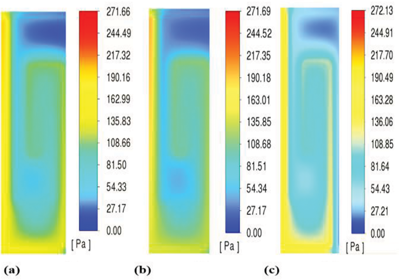
Figure 8: The pressure fluctuation in the membrane when RH is 30%, 60% and 80%, respectively
One crucial factor to take into account when designing flow fields is the pressure drop. A well-designed flow field should minimize pressure losses while guaranteeing that reactants are distributed uniformly throughout the fuel cell’s active region. A more uniform pressure distribution is essential for optimizing the performance of PEMFCs, and the results presented in Fig. 8 suggest that this can be accomplished by optimizing the flow channel geometry [19,21]. The relationship between pressure drops and humidity also highlights the importance of thermal and hydrodynamic interactions within the fuel cell. As humidity increases, the flow characteristics change, which can lead to variations in pressure drop. This interplay must be carefully managed to prevent issues such as flooding or dry-out conditions, which can severely impact the efficiency of fuel cells [16,17]. The importance of pressure distribution in PEMFCs and how relative humidity affects it. Comprehending these dynamics is essential for refining designs of flow fields and guaranteeing fuel cell efficiency. Future research can benefit from the understanding this analysis provides and development efforts aimed at enhancing the performance and reliability of PEMFC systems [20,32].
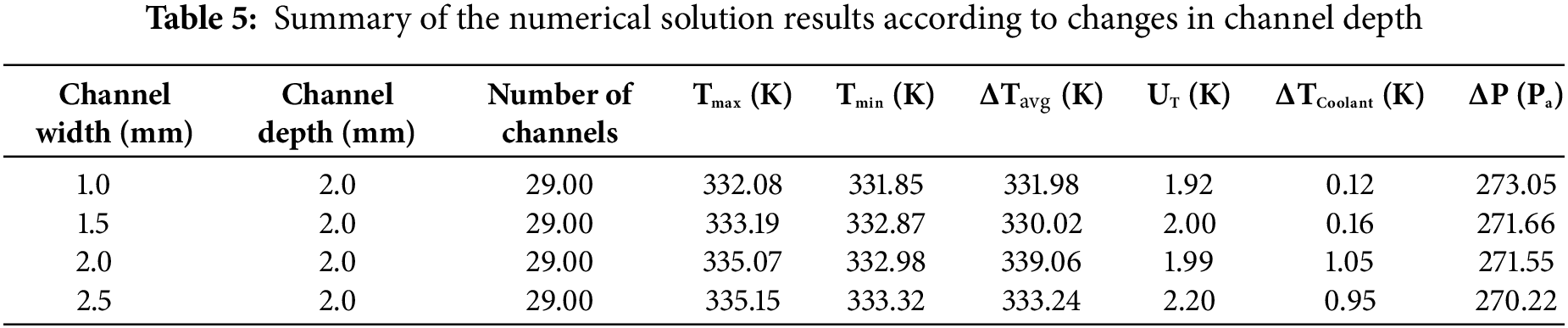
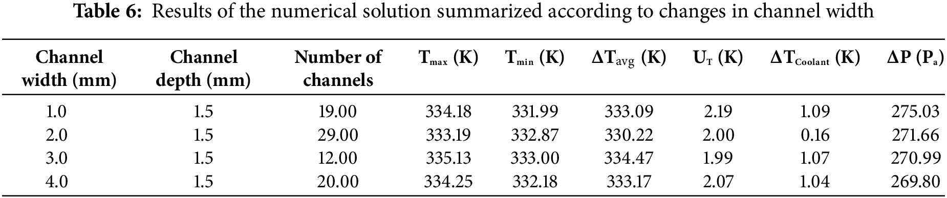
Influence of channel depth on cooling plate surface maximum temperature: Fig. 9 displays index temperature uniformity and pressure drop. Additionally, Fig. 10 illustrates the connection between the cooling plate and the channel width surface maximum temperature, pressure drop, and temperature uniformity index.
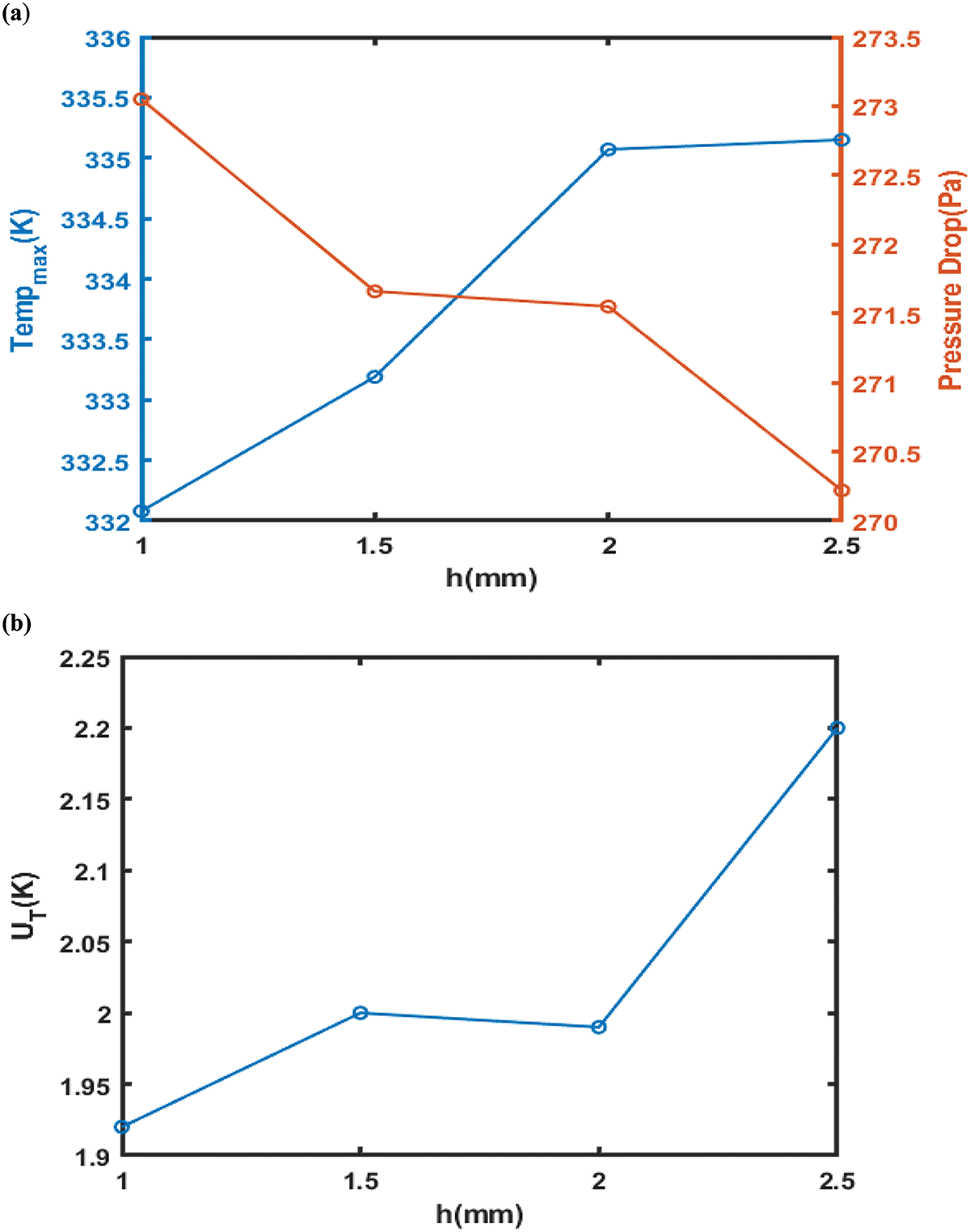
Figure 9: (a) Effect of channel depth maximum temperature and pressure drops (b) Effect of channel depths on temperature uniformity index
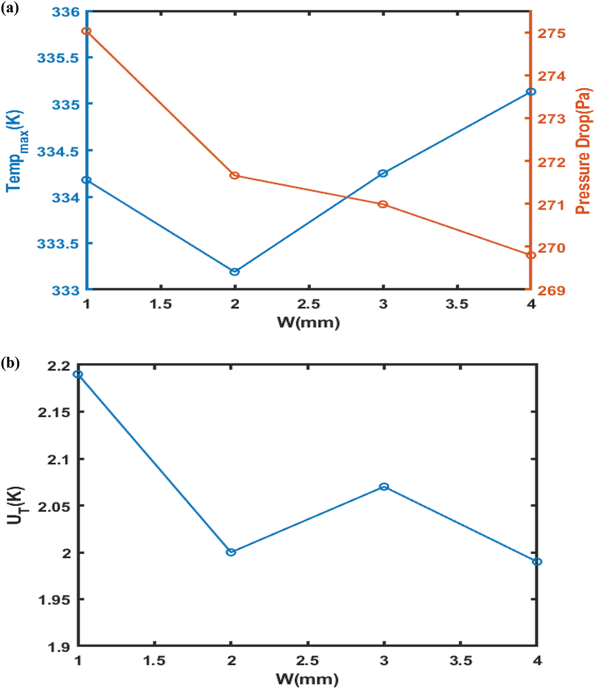
Figure 10: (a) Influence of channel width on the highest temperature and pressure drops (b) Effect of channel width on temperature uniformity index
Table 5 and Fig. 9 show how increasing the cooling plate’s maximum surface uniformity of temperature and index temperature is achieved by extending the channel depth, which simultaneously reduces pressure drop. A rise in channel widths causes the cooling surface’s plate to rise at its maximum temperature, as shown in Fig. 10. This raises the temperature uniformity index and pressure drop. Thus, it follows that it is not desirable to raise the channel depth in relation to thermal indices and that decreasing the channel depth is more appropriate for the channels. This pattern is reminiscent of a previous investigation by [18,26]. However, machining problems prevent a significant decrease in the channel’s depth. The pressure drop values between 0.15 and 0.2 mm do not significantly differ from one another. It is also not recommended to use a channel less than 0.1 mm deep due to problems with construction and decreased mechanical resistance. The outcomes did not conflict with the research [36,47]. Thus, it is preferable to use channels that are 0.1 mm deep. Each performance measure encompasses the highest temperature typical warmth; as channel width increases, temperature variation across the surface of the cooling plate, pressure, temperature uniformity index, and cooling temperature decline rate all decrease. An increase in channel width of more than 0.25 mm minimizes cooling efficiency. Channel width increases but the number of channels decreases when the distance between the channels stays constant. The result perfectly agrees with the findings of [18]. The channels’ cross-sectional measurements have been held ongoing to ascertain channel spacing. Table 6 summarizes the findings and shows how variations in channel width-depth affect the PEMFC cooling plate's thermal performance. The cooling plate's maximum temperature rises as channel width increases, illustrating the direct correlation between channel dimensions and fuel cell heat distribution. Specifically, the temperature uniformity index rises with certain channel configurations, UT, which could indicate potential avenues for increasing cooling effectiveness [51,52]. According to comparative studies, a decrease in channel depth can improve cooling efficiency by reducing pressure drop and increasing heat transfer. This finding indicates that when creating thermal management plans for PEMFC applications, the ideal balance between channel size and performance metrics should be struck [51]. These findings, which are further supported by approaches reported in earlier research, demonstrate that the channel design parameters are crucial for maximizing the effectiveness and performance of the cooling systems in PEMFCs.
This conclusion indicates that by optimizing the design of the cooling channels within the PEMFC, the difference in temperature across the fuel cell (the temperature gradient) is significantly decreased. A lower temperature gradient is beneficial because it promotes uniform temperature distribution, which is essential for the efficient operation within the fuel cell. The fuel cell’s maximum temperature can be decreased by as much as 15% when using optimized cooling designs compared to traditional cooling methods. This reduction is crucial because excessive temperatures can result in inefficiencies and possible harm to the fuel cell’s constituent elements. Implementation of serpentine flow patterns in the cooling channels led to a 20% increase in convective heat transfer is measured by the Nusselt number. This increase suggests that the new design facilitates better heat transfer between the coolant and the fuel cell, thereby improving the overall cooling efficiency. Effective cooling strategies can enhance the performance of the PEMFC by 10%. This improvement is significant and indicates that better thermal management can lead to more efficient energy production, especially under varying operational conditions such as different pressures and humidity levels. Optimizing the cooling flow design is essential for maximizing PEMFC performance and dependability. It suggests that careful consideration of cooling strategies is necessary for fuel cell technology to be successfully implemented in practical situations.
i. The optimized cooling channel design significantly reduces the temperature gradient across the PEMFC, enhancing overall efficiency.
ii. Compared to traditional cooling designs, a reduction in the maximum temperature by up to 15% was achieved.
ii. Implementing serpentine flow patterns resulted in a 20% increase in the Nusselt number, indicating improved heat transfer rates.
iv. Effective cooling strategies can lead to a 10% increase in fuel cell performance under varying operational conditions (pressures of 2 bar and relative humidity levels of 30%, 60%, and 80%), respectively.
v. The study emphasizes how important cooling flow design is to maximizing PEMFC performance and dependability.
Future Recommendations
i. Develop adaptive thermal management systems that optimize coolant flow and temperatures in real-time and explore hybrid energy systems that integrate wind and solar power in PEMFCs to increase sustainability and efficiency.
ii. Investigate various coolant channel designs and materials to balance performance improvements with cost-effectiveness and conduct research on the performance of coolant channel designs under varying conditions (humidity, pressure, temperature) to optimize fuel cell operation.
iii. Enhance computational fluid dynamics (CFD) methods for better simulation accuracy in heat transfer and fluid flow studies and perform long-term assessments of PEMFC durability and performance under real-world conditions to ensure practical application viability.
iv. Prioritize innovative designs for effective water management to prevent flooding, maintain optimal performance, and foster collaboration among researchers, engineers, and industry stakeholders to accelerate advancements in PEMFC technology.
Acknowledgement: The authors acknowledge the support of the Student’s Innovation Center at the College of Energy Engineering, Zhejiang University, China.
Funding Statement: This work was supported by Zhejiang Province Spearhead and Leading Goose Research and Development Key Program (2023C01239) 2023 Zhejiang Province “Jianbing” “Lingyan” R&D Research and Development Plan Project-Ultra-Long Endurance Hydrogen-Electric Hybrid Unmanned Aerial Vehicle 2023C01239.
Author Contributions: The authors confirm their contribution to the paper as follows: study conception and design: Abubakar Unguwanrimi Yakubu, Shusheng Xiong; data collection: Qi Jiang, Jiahao Zhao; analysis and interpretation of results: Xuanhong Ye, Junyi Liu, Qinglong Yu; draft manuscript preparation: Abubakar Unguwanrimi Yakubu. All authors reviewed the results and approved the final version of the manuscript.
Availability of Data and Materials: The data and materials used in this study are available upon request. Interested parties can contact the corresponding author, Prof. Dr. Shusheng Xiong, to obtain access to the data and materials.
Ethics Approval: Not applicable.
Conflicts of Interest: The authors declare no conflicts of interest to report regarding the present study.
References
1. Zhao J, Jian Q, Huang Z. Experimental study on heat transfer performance of vapor chambers with potential applications in thermal management of proton exchange membrane fuel cells. Appl Therm Eng. 2020 Nov;180:115847. doi:10.1016/j.applthermaleng.2020.115847. [Google Scholar] [CrossRef]
2. Ijaodola OS, El- Hassan Z, Ogungbemi E, Khatib FN, Wilberforce T, Thompson J, et al. Energy efficiency improvements by investigating the water flooding management on proton exchange membrane fuel cell (PEMFC). Energy. 2019 Jul;179(1):246–67. doi:10.1016/j.energy.2019.04.074. [Google Scholar] [CrossRef]
3. Hasheminasab M, Bozorgnezhad A, Shams M, Ahmadi G, Kanani H. Simultaneous investigation of PEMFC performance and water content at different flow rates and relative humidities. In: ASME 2014 12th International Conference on Nanochannels, Microchannels and Minichannels; 2014 Aug 3–7; Chicago, IL, USA. [Google Scholar]
4. Yakubu AU, Zhao J, Jiang Q, Ye X, Liu J, Yu Q, et al. A comprehensive review of primary cooling techniques and thermal management strategies for polymer electrolyte membrane fuel cells PEMFC. Heliyon. 2024 Sep;10(19):2405–8440. doi:10.1016/j.heliyon.2024.e38556. [Google Scholar] [PubMed] [CrossRef]
5. Xu X, Zhang L, Wang S, Han D, You S, Zhou J. Numerical and experimental analyses of a novel type PEMFC coolant channel. Int J Hydrog Energy. 2024 Jan;49(4):652–73. doi:10.1016/j.ijhydene.2023.08.355. [Google Scholar] [CrossRef]
6. Azarafza A, Ismail MS, Rezakazemi M, Pourkashanian M. Comparative study of conventional and unconventional designs of cathode flow fields in PEM fuel cell. Renew Sustain Energ Rev. 2019 Dec;116(4):109420. doi:10.1016/j.rser.2019.109420. [Google Scholar] [CrossRef]
7. Lim IS, Park JY, Choi EJ, Kim MS. Efficient fault diagnosis method of PEMFC thermal management system for various current densities. Int J Hydrog Energy. 2021 Jan;46(2):2543–54. doi:10.1016/j.ijhydene.2020.10.085. [Google Scholar] [CrossRef]
8. Bégot S, Harel F, Lepiller V, Hafsa Saidouni W. A new cooling circuit and its control strategies for the thermal management of PEMFC in rapid startup application. Int J Hydrog Energy. 2023 Jan;48(34):12826–43. doi:10.1016/j.ijhydene.2022.12.166. [Google Scholar] [CrossRef]
9. Wen D, Yin L, Piao Z, Li G, Leng QH. Performance investigation of proton exchange membrane fuel cell with intersectant flow field. Int J Heat Mass Transf. 2018 Jun;121(4):775–87. doi:10.1016/j.ijheatmasstransfer.2018.01.053. [Google Scholar] [CrossRef]
10. Guo N, Leu MC, Koylu UO. Bio-inspired flow field designs for polymer electrolyte membrane fuel cells. Int J Hydrog Energy. 2014 Dec;39(36):21185–95. doi:10.1016/j.ijhydene.2014.10.069. [Google Scholar] [CrossRef]
11. Asadi MR, Ghasabehi M, Ghanbari S, Shams M. The optimization of an innovative interdigitated flow field proton exchange membrane fuel cell by using artificial intelligence. Energy. 2023 May;290:130131. doi:10.1016/j.energy.2023.130131. [Google Scholar] [CrossRef]
12. Zhang G, Kandlikar SG. A critical review of cooling techniques in proton exchange membrane fuel cell stacks. Int J Hydrog Energy. 2012 Feb;37(3):2412–29. doi:10.1016/j.ijhydene.2011.11.010. [Google Scholar] [CrossRef]
13. Huang Z, Jian Q. Cooling efficiency optimization on air-cooling PEMFC stack with thin vapor chambers. Appl Therm Eng. 2022 Nov;217(2):119238. doi:10.1016/j.applthermaleng.2022.119238. [Google Scholar] [CrossRef]
14. Yu X, Tu Z, Chan SH. Thermal management on an air-cooled PEMFC stack with concave-convex dual flow channel bipolar plates. Int J Hydrog Energy. Jan 2024;52:1018–32. doi:10.1016/j.ijhydene.2023.05.151. [Google Scholar] [CrossRef]
15. Kanani H, Shams M, Hasheminasab M, Bozorgnezhad A. Model development and optimization of operating conditions to maximize PEMFC performance by response surface methodology. Energy Convers Manag. 2015 March;93(2):9–22. doi:10.1016/j.enconman.2014.12.093. [Google Scholar] [CrossRef]
16. Jeon DH, Kim KN, Baek SM, Nam JH. The effect of relative humidity of the cathode on the performance and the uniformity of PEM fuel cells. Int J Hydrog Energy. 2011;36(19):12499–511. doi:10.1016/j.ijhydene.2011.06.136. [Google Scholar] [CrossRef]
17. Wang L, Husar A, Zhou T, Liu H. A parametric study of PEM fuel cell performances. Int J Hydrog Energy. 2003 Nov;28(11):1263–72. doi:10.1016/S0360-3199(02)00284-7. [Google Scholar] [CrossRef]
18. Perng SW, Wu HW, Wang RH. Effect of the modified flow field on non-isothermal transport characteristics and cell performance of a PEMFC. Energy Convers Manag. 2014 Apr;80:87–96. doi:10.1016/j.enconman.2013.12.044. [Google Scholar] [CrossRef]
19. Ting FP, Hsieh CW, Weng WH, Lin JC. Effect of operational parameters on the performance of PEMFC assembled with Au-coated Ni-foam. Int J Hydrog Energy. 2012 Sep;37(18):13696–703. doi:10.1016/j.ijhydene.2012.02.142. [Google Scholar] [CrossRef]
20. Zheng B, Deng C, Luo R, Gao S, Ji F, Wang D. Mechanically strengthened polybenzimidazole membrane via a two-step crosslinking strategy for high-temperature proton exchange membrane fuel cell. J Power Sources. 2024 May;603(12):234369. doi:10.1016/j.jpowsour.2024.234369. [Google Scholar] [CrossRef]
21. Afshari E, Jahantigh N, Atyabi SA. Configuration of proton exchange membrane fuel cell gas and cooling flow fields. PEM Fuel Cells. 2022;129(2):429–63. doi:10.1016/B978-0-12-823708-3.00008-0. [Google Scholar] [CrossRef]
22. Santarelli MG, Torchio MF. Experimental analysis of the effects of the operating variables on the performance of a single PEMFC. Energy Convers Manag. 2007 Jan;48(1):40–51. doi:10.1016/j.enconmon.2006.05.013. [Google Scholar] [CrossRef]
23. Williams MV, Kunz HR, Fenton JM. Operation of Nafion®-based PEM fuel cells with no external humidification: influence of operating conditions and gas diffusion layers. J Power Sources. 2004 Sep;135(1–2):122–34. doi:10.1016/j.jpowsour.2000.04.04.010. [Google Scholar] [CrossRef]
24. Zhang J, Wu J, Zhang H. PEM fuel cell testing and diagnosis. 1st ed. Canada: Newnes, Elsevier, National Research Council of Canada; 2013 Mar 25. p. 5–10. [Google Scholar]
25. Yan WM, Chen F, Wu HY, Soong CY, Chu HS. Analysis of thermal and water management with temperature-dependent diffusion effects in the membrane of proton exchange membrane fuel cells. J Power Sources. 2004 Apr;129(2):127–37. doi:10.1016/j.jpowsour.2003.11.028. [Google Scholar] [CrossRef]
26. Chen T, Liu S, Gong S, Wu C. Development of bipolar plates with different flow channel configurations based on plant vein for fuel cell. Int J Energy Res. 2013 Apr;37(13):1680–8. doi:10.1002/er.3033. [Google Scholar] [CrossRef]
27. Yan WM, Chen CY, Mei SC, Soong CY, Chen F. Effects of operating conditions on cell performance of PEM fuel cells with conventional or interdigitated flow field. J Power Sources. 2006 Nov;162(2):1157–64. doi:10.1016/j.jpowsour.2006.07.044. [Google Scholar] [CrossRef]
28. Guvelioglu GH, Stenger HG. Flow rate and humidification effects on a PEM fuel cell performance and operation. J Power Sources. 2007 Jan;163(2):882–91. doi:10.1016/j.jpowsour.2006.09.052. [Google Scholar] [CrossRef]
29. Scholta J, Berg N, Wilde P, Jörissen L, Garch J. Development and performance of a 10 kW PEMFC stack. J Power Sources. 2004 Mar;127(1–2):206–12. doi:10.1016/j.jpowsour.2006.09.040. [Google Scholar] [CrossRef]
30. Santarelli MG, Torchio MF, Calı M, Giaretto V. Experimental analysis of cathode flow stoichiometry on the electrical performance of a PEMFC stack. Int J Hydrog Energy. 2007 May;32(6):710–6. doi:10.1016/j.ijhhydene.2006.08.008. [Google Scholar] [CrossRef]
31. Wahdame B, Candusso D, François X, Harel F, De Bernardinis A, Kauffmann JM, et al. Study of a 5 kW PEMFC using experimental design and statistical analysis techniques. Fuel Cells. 2007 Feb;7(1):47–62. doi:10.1002/fuce.200500256. [Google Scholar] [CrossRef]
32. Musio F, Tacchi F, Omati L, Gallo Stampino P, Dotelli G, Limonta S, et al. PEMFC system simulation in MATLAB-Simulink® environment. Int J Hydrog Energy. 2011 Jul;36:8045–52. doi:10.1016/j.ijhhydene.2011.01.093. [Google Scholar] [CrossRef]
33. Afshari E, Mosharaf-Dehkordi M, Rajabian H. An investigation of the PEM fuel cells performance with partially restricted cathode flow channels and metal foam as a flow distributor. Energy. 2017 Jan;118:705–15. doi:10.1016/j.energy.2016.10.101. [Google Scholar] [CrossRef]
34. Wu HW, Gu HW. Analysis of operating parameters considering flow orientation for the performance of a proton exchange membrane fuel cell using the Taguchi method. J Power Sources. 2010 Jun;195(11):3621–30. doi:10.1016/j.jpowsour.2009.11.128. [Google Scholar] [CrossRef]
35. Mahdavi A, Ranjbar AA, Gorji M, Rahimi-Esbo M. Numerical simulation-based design for an innovative PEMFC cooling flow field with metallic bipolar plates. Appl Energy. 2018 Oct;228:656–66. doi:10.1016/j.apenergy.2018.06.101. [Google Scholar] [CrossRef]
36. Sharif E, Jahantigh N, Ziaei-Rad M. Parametric study of the influence of cooling channel dimensions on PEM fuel cell thermal performance. Hydrog Fuel Cell Energy Storage. 2018 Jan;4(4):265–74. doi:10.22104/ijhfc.2018.2565.1158. [Google Scholar] [CrossRef]
37. Kanani Y, Karmakar A, Acharya S. Phase-change process inside a small-radii cylinder subjected to cyclic convective boundary conditions: a numerical study. J Heat Transf. 2021 Oct;143(10):102401. doi:10.1115/1.4052085. [Google Scholar] [CrossRef]
38. Hashemi F, Rowshanzamir S, Rezakazemi M. CFD modeling of serpentine flow fields in PEMFCs: validation and optimization. Int J Hydrog Energy. 2022;47:12345–56. [Google Scholar]
39. Wu HW, Ku HW. Effects of the modified flow field on optimal parameters estimation and cell performance of a PEM fuel cell with the Taguchi method. Int J Hydrog Energy. 2012 Jan;37(2):1613–27. doi:10.1016/j.ijhydene.2011.09.115. [Google Scholar] [CrossRef]
40. Solehati N, Bae J, Sasmito AP. Optimization of operating parameters for liquid-cooled PEM fuel cell stacks using Taguchi method. J Ind Eng Chem . 2012 May;18(3):1039–50. doi:10.1016/j.jiec.2011.12.003. [Google Scholar] [CrossRef]
41. Rao SSL, Shaija A, Jayaraj S. Optimization of operating parameters to maximize the current density without flooding at the cathode membrane interface of a PEM fuel cell using Taguchi method and genetic algorithm. Int J Energy Environ. 2014 May;5(3):335–52. [Google Scholar]
42. Zhao X, Li Y, Liu Z, Li Q, Chen W. Thermal management system modeling of a water-cooled proton exchange membrane fuel cell. Int J Hydrog Energy. 2015 Feb;40(7):3048–56. doi:10.1016/j.ijhydene.2014.12.026. [Google Scholar] [CrossRef]
43. Amirfazli A, Asghari S, Sarraf M. An investigation into the effect of manifold geometry on uniformity of temperature distribution in a PEMFC stack. Energy. 2018 Feb;145(38):141–51. doi:10.1016/j.energy.2017.12.124. [Google Scholar] [CrossRef]
44. Liu Q, Xu H, Lin Z, Zhu Z, Wang H, Yuan Y. Experimental study of the thermal and power performances of a proton exchange membrane fuel cell stack affected by the coolant temperature. Appl Therm Eng.2023 Feb;225:120211. doi:10.1016/j.applthermaleng.2023.120211. [Google Scholar] [CrossRef]
45. Choi M, Kim M, Sohn YJ, Kim SG. Development of preheating methodology for a 5 kW HT-PEMFC system. Int J Hydrog Energy. 2021 Oct;46(74):36982–94. doi:10.1016/j.ijhydene.2021.08.197. [Google Scholar] [CrossRef]
46. Li S, Sundén B. Numerical study on the thermal performance of non-uniform flow channel designs for cooling plates of PEM fuel cells. Numer Heat Transf Part A: Appl. 2018 Aug;74(1):917–30. doi:10.1080/10407782.2018.1486642. [Google Scholar] [CrossRef]
47. Ghasemi M, Ramiar A, Ranjbar AA, Rahgoshay SM. A numerical study on thermal analysis and cooling flow fields effect on PEMFC performance. Int J Hydrog Energy. 2017 Sep;42( 38):24319–37. doi:10.1016/j.ijhydene.2017.08.036. [Google Scholar] [CrossRef]
48. Chen Q, Zhang G, Zhang X, Sun C, Jiao K, Wang Y. Thermal management of polymer electrolyte membrane fuel cells: a review of cooling methods, material properties, and durability. Appl Energy. 2021 Mar;286(1):116496. doi:10.1016/j.apenergy.2021.116496. [Google Scholar] [CrossRef]
49. Ji MB, Wei ZD. A review of water management in polymer electrolyte membrane fuel cells. Energies. 2009 Nov;2(4):1057–106. doi:10.3390/en20401057. [Google Scholar] [CrossRef]
50. Pasaogullari U, Wang CY, Chen KS. Two-phase transport in polymer electrolyte fuel cells with bilayer cathode gas diffusion media. J Electrochem Soc. 2005 Jul;152(8):1574. doi:10.1149/1.1938067. [Google Scholar] [CrossRef]
51. Fu RS, Khajeh-Hosseini-Dalasm N, Pasaogullari U. Numerical validation of water transport in a polymer electrolyte membrane. ECS Trans. 2013 May;50(2):967. doi:10.1149/05002.0967ecst. [Google Scholar] [CrossRef]
52. Yu Y, Chen M, Zaman S, Xing S, Wang M, Wang H. Thermal management system for liquid-cooling PEMFC stack: from primary configuration to system control strategy. eTransportation. 2022 May;12(2):100165. doi:10.1016/j.etran.2022.100165. [Google Scholar] [CrossRef]
53. Sun J, Guo Z, Pan L, Fan XZ, Wei L, Zhao T. Redox flow batteries and their stack-scale flow fields. Carbon Neutrality. 2023 Nov;2(1):100180. doi:10.1007/s43979-023-00072-6. [Google Scholar] [CrossRef]
54. Fard MS, Rahimi M, Pahamli Y, Samadi H, Bahrampoury R. Cooling performance of sliver solar cells in low concentration PV system with a ribbed-groove mini-channel heat sink. Int J Therm Sci. 2024 Jun;200(12):108955. doi:10.1016/j.ijthermalsci.2024.108955. [Google Scholar] [CrossRef]
55. Khoshvaght-Aliabadi M, Feizabadi A, Nouri M. Design of novel geometries for mini channels to reduce junction temperature of heat sinks and enhance temperature uniformity. Appl Therm Eng. 2021 Jun;192(1–2):116926. doi:10.1016/j.applthermaleng.2021.116926. [Google Scholar] [CrossRef]
56. Baek SM, Yu SH, Nam JH, Kim CJ. A numerical study on uniform cooling of large-scale PEMFCs with different coolant flow field designs. Appl Therm Eng. 2011 Jun;31(8–9):1427–34. doi:10.1016/j.applthermaleng.2011.01.009. [Google Scholar] [CrossRef]
57. Afshari E, Ziaei-Rad M, Dehkordi MM. Numerical investigation on a novel zigzag-shaped flow channel design for cooling plates of PEM fuel cells. J Energy Inst. 2017 Oct;90(5):752–63. doi:10.1016/j.joei.2016.07.002. [Google Scholar] [CrossRef]
58. Song J, Huang Y, Liu Y, Ma Z, Chen L, Li T, et al. Numerical investigation and optimization of cooling flow field design for proton exchange membrane fuel cell. Energies. 2022 Apr;15(7):2609. doi:10.3390/en15072609. [Google Scholar] [CrossRef]
59. Zhang G, Jiao K. Multi-phase models for water and thermal management of proton exchange membrane fuel cell: a review. J Power Sources. 2018 Jul;391(1):120–33. doi:10.1016/j.jpowsour.2018.04.071. [Google Scholar] [CrossRef]
60. Lim BH, Majlan EH, Daud WRW, Rosli MI, Husaini T. Numerical analysis of modified parallel flow field designs for fuel cells. Int J Hydrog Energy. 2017 Apr;42(14):9210–18. doi:10.1016/j.ijhydene.2016.03.189. [Google Scholar] [CrossRef]
Cite This Article
 Copyright © 2025 The Author(s). Published by Tech Science Press.
This work is licensed under a Creative Commons Attribution 4.0 International License , which permits unrestricted use, distribution, and reproduction in any medium, provided the original work is properly cited.
 Downloads
 Citation Tools