
 Submit a Paper
 Propose a Special lssue
 Open Access
ARTICLE

Retrofitting Design of a Deep Drilling Rig Mud Pump Load Balancing System
Faculty of Mechanical Engineering and Naval Architecture, University of Zagreb, Zagreb, HR-10000, Croatia
* Corresponding Author: Danijel Pavković. Email:
(This article belongs to the Special Issue: Selected Papers from the SDEWES 2024 Conference on Sustainable Development of Energy, Water and Environment Systems)
Energy Engineering 2025, 122(5), 1669-1696. https://doi.org/10.32604/ee.2025.061916
Received 06 December 2024; Accepted 17 March 2025; Issue published 25 April 2025
 View Full Text
 Download PDF
Abstract
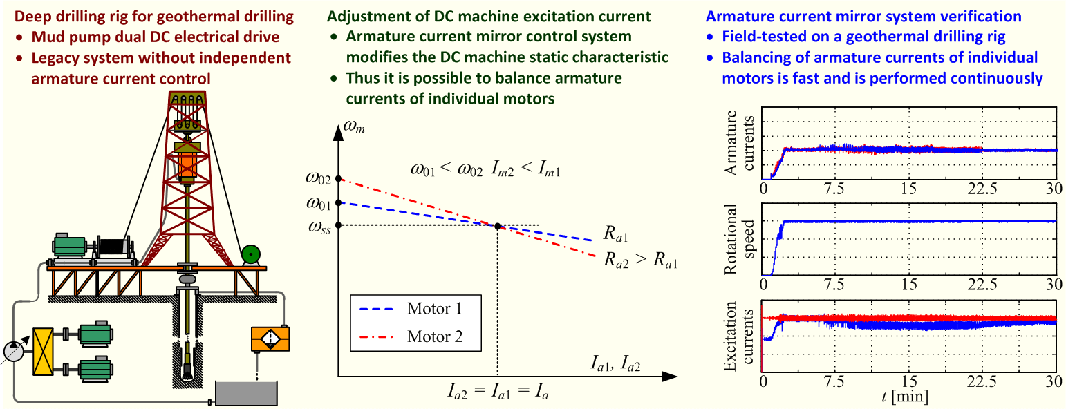
In deep drilling applications, such as those for geothermal energy, there are many challenges, such as those related to efficient operation of the drilling fluid (mud) pumping system. Legacy drilling rigs often use paired, parallel-connected independent-excitation direct-current (DC) motors for mud pumps, that are supplied by a single power converter. This configuration results in electrical power imbalance, thus reducing its efficiency. This paper investigates this power imbalance issue in such legacy DC mud pump drive systems and offers an innovative solution in the form of a closed-loop control system for electrical load balancing. The paper first analyzes the drilling fluid circulation and electrical drive layout to develop an analytical model that can be used for electrical load balancing and related energy efficiency improvements. Based on this analysis, a feedback control system (so-called “current mirror” control system) is designed to balance the electrical load (i.e., armature currents) of parallel-connected DC machines by adjusting the excitation current of one of the DC machines, thus mitigating the power imbalance of the electrical drive. The proposed control system effectiveness has been validated, first through simulations, followed by experimental testing on a deep drilling rig during commissioning and field tests. The results demonstrate the practical viability of the proposed “current mirror” control system that can effectively and rather quickly equalize the armature currents of both DC machines in a parallel-connected electrical drive, and thus balance both the electrical and mechanical load of individual DC machines under realistic operating conditions of the mud pump electrical drive.Graphic Abstract
Keywords
Recently, geothermal energy has garnered interest as a renewable energy source for applications such as building heating [1] and industrial processes [2]. The technology of single-well geothermal heating has recently gained attention as a novel way to heat buildings, so a mathematical model has been proposed in [1] to assess the possibilities of reducing the thermal resistance and increasing the effectiveness of the overall geothermal heating system. Accurate prediction of drilling costs is crucial for the development of ultra-deep geothermal wells [3], thus aiding in budgetary planning and improving the project’s return of the investment.
Deep drilling applications, such as those used in geothermal well production, pose significant challenges regarding energy efficiency and environmental sustainability [4]. The drilling process itself demands substantial energy consumption to power the heavy machinery, circulate drilling fluids, and manage waste products, which creates a substantial carbon footprint [4]. Additionally, drilling fluids can contain chemicals which could be potentially harmful to surrounding ecosystems if not properly handled [5]. Mitigating these impacts requires careful planning for optimized energy use, the selection of less harmful drilling fluids, and the implementation of robust waste management and disposal strategies [6]. Furthermore, ongoing research into new drilling methods and modern drilling equipment with reduced environmental footprints holds promise for the future of deep drilling operations [7].
One of the ways in which any industrial process can be made more environmentally friendly, especially in terms of energy efficiency, would be through replacing the old drilling equipment that is frequently less efficient and more demanding in terms of maintenance with new one [8]. However, any mature industrial machinery technology, especially that used for heavy-duty applications, can be very difficult to replace from the standpoint of costs and time required for the replacement, field testing, and commissioning [8]. Hence, this could be an unsustainable solution for many small-to-medium scale companies, which prompts those companies to seek alternative means of prolonging the useful service life of mature equipment through retrofitting [9]. It has been shown in [10] that retrofitting deep drilling rigs can represent a small fraction of the brand-new equipment costs, thus making retrofitting quite affordable compared to complete replacement (which may also entail dismantling and salvaging costs). With heavy-duty equipment for deep drilling (see, e.g., [11]) having multiple applications, especially in the context of exploration and exploitation of geothermal energy [12], it is worthwhile examining the possibility of adapting and modifying the existing deep drilling rigs [13] and their electrical drive systems with the minimum of added costs.
High-power electrical drives are classified as those ranging in their rated power from just under 1 to 10 MW and more [14]. In applications that require such electrical drives, opting for partial or full retrofitting instead of purchasing brand-new turnkey solutions can result in significant savings, especially when considering that high-power electrical machines can easily have a life cycle of 30 years or more, which can be further extended through retrofitting [15]. One of the main issues with controlled electrical drives is that electrical drive power converter life cycles are typically estimated to lie between 10 and 20 years of continuous operation [16], while the provision of spare parts by the power converter equipment manufacturer may not be extended indefinitely for the product line in question [15]. In some applications, the maintenance costs may play a crucial role regarding the choice between retrofitting and replacement, such as in the case of direct-current (DC) electrical drives [17]. In all those cases, it is upon the operator to assess which kind of upgrade is the most favorable in terms of cost, service, electrical drive reliability, and availability of suitable drive vendors [15].
The most convenient and flexible upgrades in electrical drive systems are those related to service software and its specialized functions [15]. This is especially the case for electrical drives that need to satisfy precise speed control in the presence of emphasized transmission compliance and friction [18], but also for any other type of nonlinear behavior within the drive that degrades the electrical drive performance. One of the most challenging problems in deep drilling applications is the coordinated control of pumps for drilling fluid (mud) circulation, whose electrical drives need to be speed-controlled to maintain the required fluid flow rate while being subject to notable pressure pulsations due to piston-type pumps used in such heavy-duty applications [9]. Good mitigation of pressure pulsations can be achieved by synchronizing the axle positions of motors driving individual pumps with respect to piston position [19], and such commercial solutions are already available for modern controlled electrical drives [20].
Such open-loop controlled electrical drives utilizing high-power independent excitation direct-current (DC) electrical machines can still be found in the field, such as on the heavy-duty deep drilling rig utilizing a dual DC electrical machine pump drive [21]. The drilling rig in question has been recently retrofitted with modern power electronics systems (DC motor power converters) [22] configured for open-loop speed adjustment of the pump drive via armature voltage and excitation current control. In that application resembling the original (legacy) solution, the armatures of the two independently excited DC machines are connected in parallel and supplied from a single thyristor-based power converter [23]. This makes equalizing the current loads of individual DC motors a very challenging task, as was the case for the dual DC electrical drives being retrofitted with brand new digitally controlled thyristor-based power converter for armature power supply, which did not include the control algorithm for armature current balancing (the so-called “current mirror” control system). Namely, in such an application, the existing legacy equipment can be upgraded to a higher performance category by means of retrofitting, which may prove to be rather inexpensive when compared to purchasing brand new solutions while also prolonging the equipment’s useful service life. Some examples of successful retrofitting applications of deep drilling systems can be found in [9], wherein relatively small investments into the control hardware and software upgrades have resulted in enhanced functionality of the drilling systems in question.
In the case considered herein, the high-power electrical drives built around DC electrical machines working in tandem have been upgraded to a higher performance category by means of retrofitting the power electronics hardware and related control software, wherein the latter also included a control strategy for balancing electrical power between individual electrical machines that are operated in the open-loop configuration. This relatively inexpensive measure can be beneficial with respect to prolonging the useful service life of individual DC electrical machines and reducing their maintenance requirements. In particular, the hypothesis of this work is that a closed feedback loop can be established via a suitable controller that balances the armature currents of DC electrical machines with armatures connected in parallel on a single power converter. The selected control system structure based on measurements of armature currents of both machines and adjusting the excitation current of one of the DC machines to match the armature current drawn by the other electrical machine by means of a proportional-integral (PI) controller is termed “current mirror” control system in this paper.
The main challenges and related benefits addressed by the proposed mud pump load balancing system retrofitted to the existing dual parallel-connected DC machine-based electrical drive are as follows. Firstly, the proposed load balancing system addresses the unequal load distribution of the open-loop voltage-controlled dual DC machine electrical drive by means of feedback control action, which results in equal armature currents of individual parallel-connected DC machines. Consequently, the balancing of individual DC machine armature currents results in reduced heat losses, which, in turn, may lessen the aging of the DC machine armature winding insulation. Finally, the presented control system upgrade enables the end user to keep the existing hardware and pumping infrastructure relying on mature (legacy) industrial hardware that is still highly functional.
The paper is organized as follows. Section 2 outlines the problem of dual DC electrical drive coordination and presents the detailed mathematical model of the dual DC machine-based pumping station. Section 3 describes the structure of the load balancing control system and the straightforward practical procedure for the PI controller tuning based on a symmetrical optimum tuning procedure [24]. Section 4 presents the results of the verification of the proposed armature current load balancing control system, first through computer simulations, followed by results of field tests on an actual deep drilling rig used to produce a geothermal well. Concluding remarks and possibilities for future research are given in Section 5.
This section outlines the layout of the considered deep drilling rig mud pump system comprising a dual-motor DC machine drive and presents mathematical models of the dual DC machine electrical drive and the piston mud pump, which are then linearized for subsequent control system design.
2.1 Drilling Facility Overview
Fig. 1 shows the layout of the land-based deep drilling rig, which is built around a high-power low-speed electrical or hydraulic top drive [18] that facilitates drill-string system rotary motion (rotary drive). The combined action of the top drive and the draw-works hoist electrical drive results in continuous borehole drilling wherein the drill-string torque, drill-string rate-of-penetration (RoP), and drill-string hook-load that defines the drill-bit normal force (weight-on-bit or WoB) need to be continuously controlled using dedicated rotary and draw-works drive control systems (see, e.g., [9]). During borehole production, the drilling fluid (drilling mud) is circulated through the borehole utilizing mud pumps powered by high-power electrical motors, thus controlling the borehole pressure and also providing lubrication and cooling for the drill bit and means of removing the pulverized rock debris from the bottom of the well [19]. In the particular application, the high-power independent excitation DC electrical machines are used for the purpose of powering the high-pressure piston pumps used for mud circulation within the borehole [21].
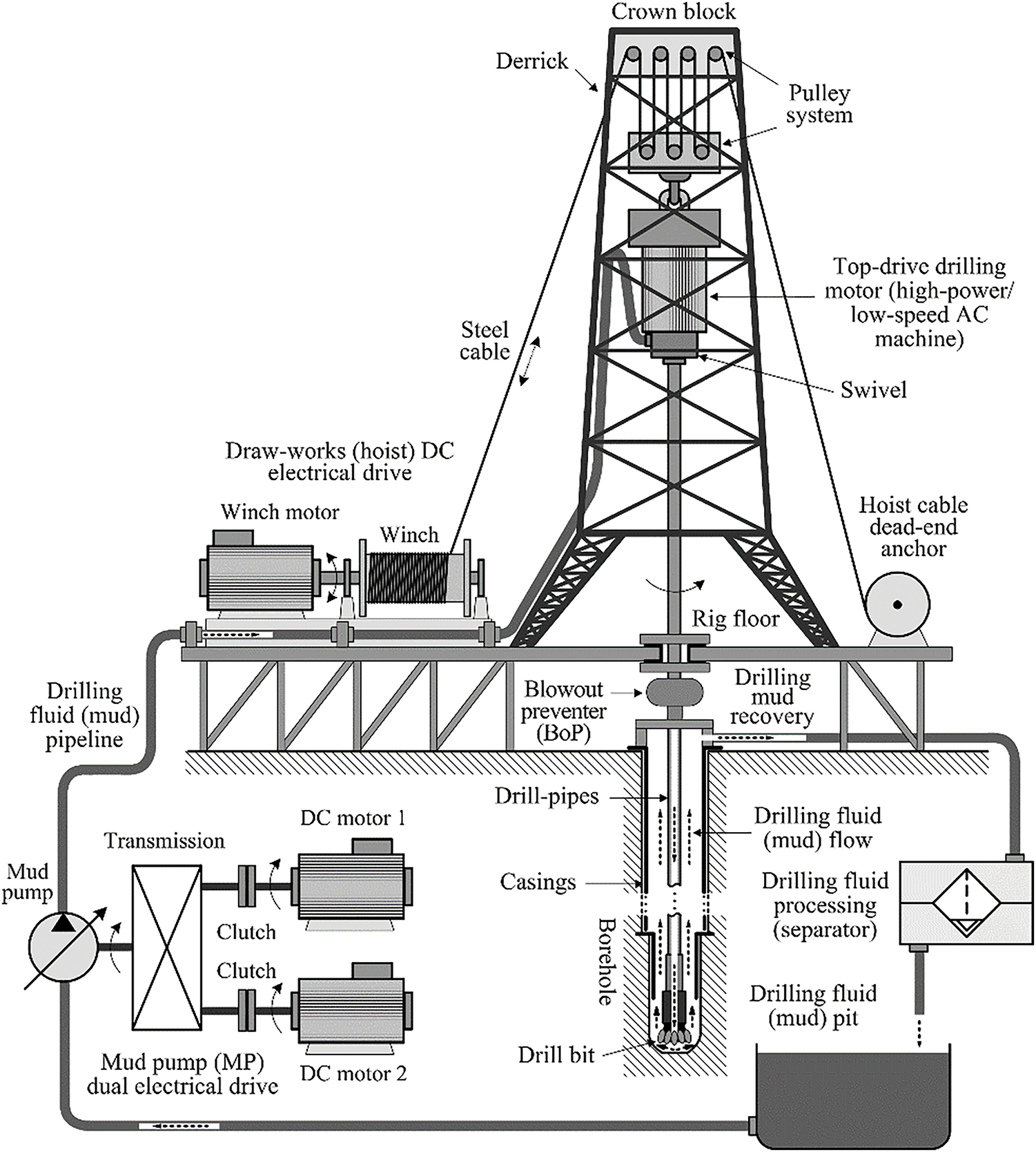
Figure 1: Schematic representation of land-based drilling rig
While alternating current (AC) electrical motors with advanced control systems have become increasingly prevalent in industrial and transport applications over the last 30 years, DC motors remain a viable option in high-power applications due to their inherent advantages, such as high starting torque (up to 400% of the nominal torque) and consistent toque characteristic over a wide speed range, which make them suitable for heavy loads and applications requiring rapid start-up of the mechanical drive [25]. Moreover, the DC machine speed adjustment is straightforward, that is it can be achieved by adjusting the voltage supplied to the motor [25]. These advantages directly translate to lower costs compared to AC electrical motor drives and related control systems, which often require complex electronics and control software. DC motors, on the other hand, require more maintenance compared to AC motors due to the use of brushes and the commutator, which may lead to increased downtime and maintenance costs compared to AC motors. AC motors, on the other hand, offer several advantages, such as durability and longevity, primarily due to the absence of brushes and higher power density compared to DC electrical machines [26]. Furthermore, AC motors can typically achieve higher rotational speeds, thus making them suitable for demanding industrial applications, such as machine tools and milling [27].
2.2 Direct-Current Dual Electrical Drive for Mud Pump
Mature high-power DC motor drives are still being based on thyristor power converters [14]. The mud pump dual DC machine electrical drive legacy solution has been based on a common high-power 6-pulse thyristor bridge for supplying the parallel-connected armatures of the two DC machines driving the piston pump [28], with separately supplied excitation circuits for each motor, as shown in Fig. 2. The pump motors in question are GE752 shunt (separate) excitation DC machines [29], whose nominal parameter values are listed in Table 1.
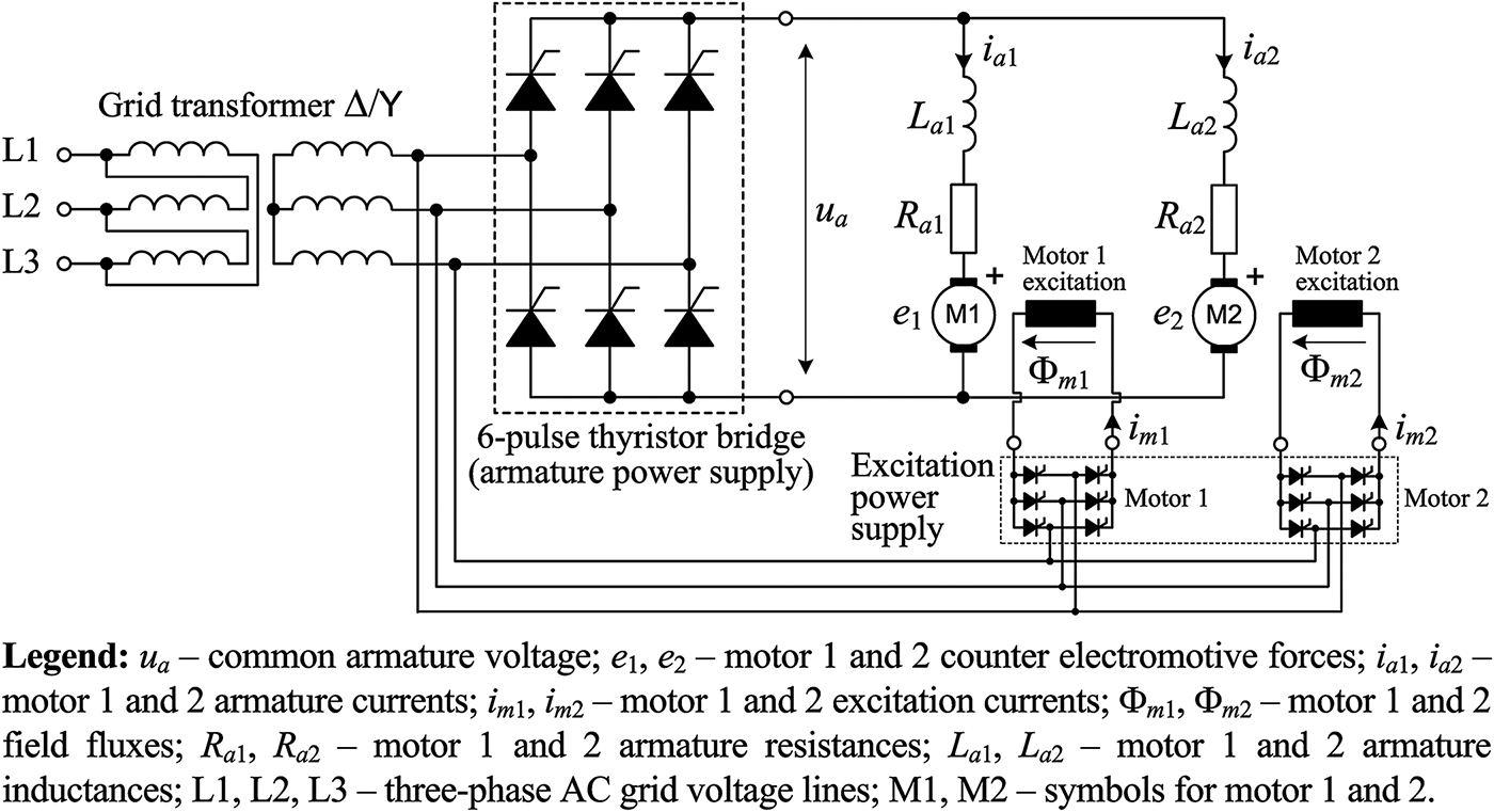
Figure 2: Topology of 6-pulse thyristor-based power converter for mud pump dual DC machine electrical drive with common armature and separate excitation circuits

These DC machines are commonly used in legacy field applications, and their retrofitting with modern thyristor-based power converters is subject of this work. It should be noted, however, that fully retrofitting the mud pump drive should entail completely replacing these legacy DC drives with more modern high-power variable-speed three-phase AC machines with appropriate voltage source inverter (VSC) based frequency converters [30]. This would greatly improve the energy efficiency and power factor of such modernized pump drives by avoiding the inherent drawback of the thyristor-based DC drives, which is related to increased reactive power requirements of DC drive topology based on a current source inverter (CSI) such as the 6-pulse thyristor bridge [31].
The nonlinear dynamic model of the dual DC machine mud pump electrical drive is obtained based on fundamental algebraic and differential equations describing the electrical and mechanical phenomena within the DC electrical machine. Namely, the DC machine armature voltage vs. current relationship is given by the following well-known differential equation [24]:
where ua and ia are the armature voltage and armature current, respectively, Ra and La are the armature winding resistance and inductance, respectively, and e is the armature induced voltage (electromotive force) defined as:
with Φm(im) representing the excitation circuit magnetization characteristics (field flux Φm vs. excitation current im curve), Ke being the electromotive force constant, and ωm being the motor rotational speed (angular speed).
The developed DC machine torque is given by the following algebraic relationship:
wherein Km is the motor torque constant.
The difference between the developed motor torque mm and the load torque at the motor axle mL determines the acceleration
Finally, the excitation current im dynamics is described by a simple first-order differential equation, which captures the dominant response characteristics of the excitation control system implemented within the power converter feeding the excitation circuit in the following way:
where imR is the excitation current reference (target) value, and Tem is the equivalent time constant (equivalent lag) of the excitation current control loop.
Based on these algebraic and differential equations, the nonlinear dynamic model of the dual DC machine mud pump electrical drive is derived and shown in Fig. 3. Dual DC machine model comprises two identical DC machine models (Eqs. (1)–(5)), whose armature circuits (characterized by armature resistances Ra1,2 and inductance La1,2) are fed by the common armature voltage ua, wherein for each motor its counter electromotive force (e1 for motor 1 and e2 for motor 2) is produced due to motors 1 and 2 excitation circuit magnetic field fluxes Φm1 and Φm2 and the pump electrical drive rotational speed ωm:
where Φm(im1,2) represents the excitation circuit magnetization characteristics (magnetic fluxes vs. excitation currents) which should be identical for DC machines of identical type, and im1 and im2 are the excitation currents for each DC motor.
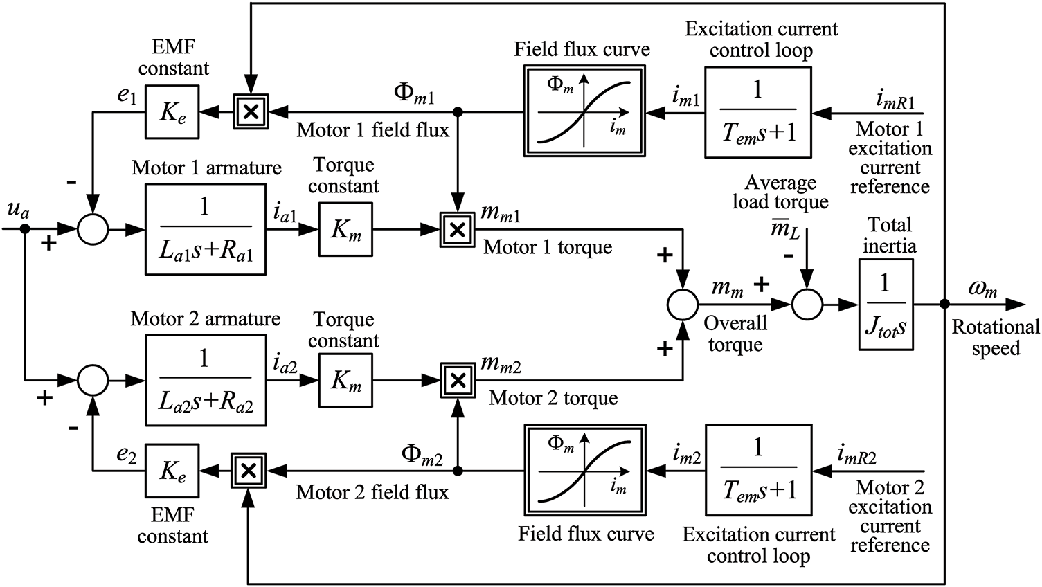
Figure 3: Block diagram of armature voltage open-loop control of dual DC machine drive with parallel-connected machine armatures and separately controlled excitation currents
The armature voltage vs. EMF difference results in armature currents ia1 and ia2 in the following way:
wherein Ra1,2 denotes the armature winding resistance of DC motors 1 and 2, and La1,2 denotes the armature winding inductance of DC motors 1 and 2.
Similarly to the case of a single DC machine, the developed torques of motors 1 and 2 (mm1 and mm2) are proportional to their respective armature currents ia1 and ia2 and magnetic field fluxes Φm1 and Φm2 as follows:
Since the dual electrical drive comprises two DC machine coupled to a single output shaft via a suitable transmission system, the resulting rotational speed ωm of the electrical drive is the consequence of a torque balance between the average load torque
where Jtot is the total drive inertia referred to the side of the dual-motor drive.
The excitation circuits of motors 1 and 2 are assumed to be current-controlled with relatively fast and aperiodic closed-loop dynamics of excitation currents im1 and im2 with respect to their current references imR1 and imR2:
with Tem being the equivalent closed-loop lag of the excitation current control system, as explained earlier (see Eq. (5)).
Fig. 3 shows the block diagram representing the nonlinear dynamic model of the parallel-connected dual DC machine electrical drive comprises the two identical DC machine models, according to Eqs. (6)–(10), whose input is the common armature voltage ua feeding the parallel-connected armature windings of each motor, and its output is the pump electrical drive rotational speed ωm.
To simplify the subsequent control system design, the nonlinear model in Fig. 3 is linearized around a specific operating point, resulting in small-perturbation models for those dual DC drive variables that incorporate nonlinear relationships between model variables, particularly those mathematical equations that incorporate the nonlinear magnetic field flux vs. magnetization characteristics (Eqs. (6) and (8)). The normalized form of the excitation circuit magnetization characteristic (field flux vs. excitation current curve Φm(im)) from [32] is shown in Fig. 4. Linearization is performed by considering small deviations (perturbations) of variables around their steady state values and calculating their total differentials. In particular, the nonlinear model in Fig. 3 is linearized in the vicinity of the operating point characterized by steady-state armature current values Ia1 and Ia2, field flux (excitation) current values Im1 and Im2 (and corresponding field fluxes Φm(Im1) and Φm(Im2)) and the steady-state drive rotational speed ωss as follows:
where Δe1,2 are motors 1 and 2 counter electromotive force perturbations, Δia1,2 are motors 1 and 2 armature current perturbations, Δim1,2 is motors 1 and 2 excitation (field) current perturbations, Φm(Im1,2) are motor 1 and 2 field flux steady-state values, Φm(Im1,2)/im1,2 are field flux curve gradients in the vicinity of steady state magnetization currents Im1,2 for motors 1 and 2, Ia1,2 are motors 1 and 2 armature current steady-state values, Δωm is the rotational speed perturbation, and ωss is the rotational speed steady-state value.
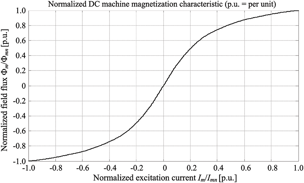
Figure 4: Excitation circuit normalized magnetization characteristic (normalized field flux vs. normalized excitation current) [32]
Thus-obtained linearized (so-called small perturbation) model of the dual-motor drive is shown in Fig. 5. Field flux curve gradients for motors 1 and 2 can be reconstructed from data points in Fig. 4 using numerical differentiation, or the field flux curve may be approximated by an analytical function, thus yielding analytical result for its gradient as well. The linearized model of the dual DC machine electrical drive in Fig. 5 is used as a basis for the design of the “current mirror” control system. The linearized model in Fig. 5 can be further simplified by introducing some realistic assumptions on the process model parameters, such as the total moment of inertia Jtot of the pump drive and the armature winding resistance parameters Ra1,2, as shown in next section.

Figure 5: Block diagram of linearized (small perturbation) model of dual DC machine drive with parallel-connected machine armatures and separately controlled excitation currents
2.3 Mud Pump Mechanical System
A mud pump is realized as a positive displacement machine, which typically consists of three cylinders, each containing a piston or a plunger within it. These pistons (plungers) are driven through respective slider-crank mechanisms and a common crankshaft powered by an external source of rotational motion (i.e., dual DC motor drive), as illustrated in Fig. 6. The volumetric flow rate is governed by the rotational speed of the crankshaft, and the number of pistons and their respective dimensions. A positive displacement pump produces a flow of fluid, whereas the downstream process or the piping system produces resistance to this flow, thereby generating pressure in the piping system and discharge portion of the pump [19].

Figure 6: Principal schematic representation of dual-motor mud pump drive system [19]
The load torque referred to the input shaft of the belt drive + gearbox transmission system (Fig. 6) is due to the in-cylinder pressure buildup (see [19]), which needs to overcome the pressure within the drill-string (pipeline) p1 to inject the drilling fluid into the pipeline. Assuming that the pressure within the cylinder is exactly equal to the pipeline pressure p1, the corresponding pulsating load torque mc due to the injection of the drilling fluid by one piston is given as follows (valid for 1/3 of revolution of the output crankshaft):
where θs is the crankshaft angle, L is the connecting rod length, r is the crankshaft radius, D is the cylinder inner diameter, and p1 is the drill-string pipeline pressure (see Fig. 6), and ig and ibelt are the gearbox transmission ratio and belt drive transmission ratio, respectively.
During one-third of the revolution of the output crankshaft wherein one cylinder is injecting drilling fluid into the drill-string pipeline, the other two cylinders are returning and drawing fluid from the supply pipeline. The average load torque of the piston pump, which may be useful for the simulation analysis of the pump electrical drive, can be calculated by integrating the pulsating load torque in Eq. (13) over the one-third of a single rotation (θs ∈ [0, 2π/3]) as follows:
where Kmp is the load torque mL vs. cylinder (borehole) fluid pressure p1 proportionality coefficient (gain).
Since only one cylinder injects fluid into the pipeline over one-third of the crankshaft revolution, the above result also represents the average load torque for continuous rotation as well. Table 2 gives the values of mechanical parameters for the piston pump from [19], based on which the average load torque can be reconstructed with respect to the drill-string pipeline mud pressure p1. Fig. 7 shows the thus obtained (linear) characteristic of the average load torque which is used in subsequent simulation analysis of the pump electrical drive behavior in Section 4.


Figure 7: Averaged load torque at the transmission input shaft (motor side)
Based on the data in Table 2, the total inertia Jtot in Eq. (4) that is referred to the transmission input (i.e., the dual-motor drive side) can be calculated as:
where Jm is the moment of inertia of a single DC motor, and Jcs and Jds are equivalent inertias of all crankshafts and driveshafts, respectively.
This section presents the control system design for motor armature current balancing (so-called current mirror system) in a dual DC motor drive with parallel-connected armature windings. The concept of armature current mirror is outlined first, followed by the proposed current mirror closed-loop system equipped with a PI controller of armature current difference designed according to symmetrical optimum criterion [24].
3.1 Problem Formulation and Principal Solution
In the dual motor drive with parallel-connected armatures supplied by a single armature voltage source ua (Fig. 3) it is not possible to compensate for the armature current variations of individual motors due to armature resistance mismatch utilizing armature voltage alone. Fig. 8a illustrates the static characteristics of individual motors within the dual motor drive with parallel-connected armatures when armature resistances Ra1 and Ra2 are not the same (Ra2 > Ra1), and for the case of equal steady-state magnetizing (excitation) currents Im1 = Im2 = Im. Since motor output shafts are coupled together via the transmission mechanism (Fig. 6), their steady-state rotational speed is the same and can be expressed as:

Figure 8: Static characteristics of dual DC drive with parallel-connected motor armatures: equal magnetizing currents case (a) and unequal magnetizing current case (b)
From the above expression, it is evident that idle speeds for both motors would be the same if magnetizing currents Im1 and Im2 were equal, which results in the following armature current ratio relationship:
Since the heat losses in armature windings of each motor are proportional to the armature current squared:
and the total armature current draw of the dual DC electrical drive is given as Itot = Ia1 + Ia2, the total power losses may be expressed in terms of the total drive current Itot as follows:
which can be directly related to total motor torque of the parallel-connected dual DC machines mtot = mm1 + mm2 in the following way (see Eqs. (7) and (9)) under the assumption of equal field fluxes Φm of individual motors (Φm1 = Φm2 = Φm):
The above analysis of load distribution between the DC electrical machines operating in parallel indicates that: (i) the DC motor with a lower value of armature resistance would draw more current from the armature voltage source ua and vice versa (Eq. (17)), (ii) the motor being subjected to much higher current draws would also be subjected to much higher mechanical load (motor torque) and would produce much higher armature winding heat losses (proportional to armature current squared), and (iii) the aforementioned effects would lead to operating temperature increase and lower energy efficiency of the motor under greater current load.
Besides the immediate effect of increased heating of the armature winding and lower energy efficiency of the motor characterized by smaller armature resistance in this parallel drive topology, possible maintenance issues may also arise during prolonged operation under unbalanced current loads due to possible accelerated aging of the winding insulation of the motor under higher current load which is associated with armature winding operation at elevated temperatures [33].
Thus, it would be preferable if both motors could be operated at the same current load, resulting in equal load distribution and less discrepancy in heat dissipation between motors:
which can be achieved by commanding different values of steady-state magnetizing currents Im1 and Im2, as shown in Fig. 8b.
In the case of different magnetizing currents (Im2 < Im1 in Fig. 8b), the resulting idle speeds for each motor are not the same:
but the static curves for motors 1 and 2 can now intersect at a point characterized by the same steady-state speed ωss and the same steady-state armature currents Ia1 = Ia2 = Ia.
By combining Eqs. (11), (13)–(15), the following relationship is obtained:
which after some manipulation and rearranging yields the following expression for the armature current that is flowing through each of the motors (i.e., motor armature currents are “mirrored”), which is adjusted through their respective magnetizing currents Im1 and Im2:
Obviously, “manual” adjustment of armature currents would require precise information about armature resistances and motor magnetizing curves, which is not practical for field applications. Therefore, a closed-loop control system is designed in the next subsection which controls the armature current of motor 2 to the “target” armature current of motor 1 via the additive magnetizing current command provided by a proportional-integral (PI) controller.
3.2 Armature “Current Mirror” Control System Design
Fig. 9a shows the conceptual block diagram of the armature “current mirror” PI controller, which adjusts the magnetizing current of motor 2 based on filtered armature current signals ia1f and ia2f from both motors. In this arrangement, motor 1 armature current ia1 may be considered as the target (reference) value that needs to be reached by motor 2 armature current ia2, which forms a negative feedback loop in this closed-loop system arrangement. The role of the “current mirror” PI controller is to: (i) minimize the armature current difference between the motor 1 and motor 2 by continuously adjusting the excitation current of motor 2 using motor 2 armature current ia2 as feedback signal, that is to provide load balancing between motor 1 and motor 2, and (ii) to compensate for variations of armature resistances, which would otherwise result in an imbalance of armature currents without the “current mirror” PI controller feedback action.

Figure 9: Conceptual block diagram of armature “current mirror” PI controller (a), simplified linearized closed-loop system representation (b), and final linearized closed-loop system (c)
The magnetizing current command ΔimR2 from the “current mirror” PI controller is added to the external constant-valued magnetizing current target value ImR2 with a reversed sign, and the total magnetizing current command imR2 is then forwarded to the magnetizing current control loop. The PI controller command ΔimR2 sign reversal is related to the proportionality effect of the field flux Φm(Im2) to the counter-electromotive force e2. Namely, a decrease in magnetizing current Im2 (field flux Φm(Im2)) would result in a decrease of electromotive force e2, which would result in an increase of the armature current ia2 due to a larger difference between armature voltage and counter-electromotive force ua–e2 (see Fig. 3).
The design of the “current mirror” control system is based on the linearized model of the dual DC machine electrical drive in Fig. 5, which can be simplified by introducing some realistic assumptions on process model parameters. Based on the data presented in Tables 1 and 2, the total inertia of the dual-motor drive according to Eq. (15) takes on a very large value (Jtot = 71.83 kgm2). This in turn means that the rotational speed perturbations Δωm due to perturbations in acceleration torque Δmm–Δ
On the other hand, for very small armature resistance values Ra1,2 (Ra1,2 ≈ 0), which are typical for high-power DC machines (Ra = 0.018 Ω, see Table 1), the armature current lag dynamics can be simplified to a pure integral model:
In addition, motor 1 excitation current im1 is assumed to be constant under excitation current closed-loop control with constant target value imR1 (its perturbations ΔimR1 are assumed to be zero). Using the above simplifications, the small-perturbation linearized model for motor 2 armature control via the “current mirror” PI controller can be approximately described by the block diagram in Fig. 9b.
Finally, by introducing the following gain factor which relates the steady-state drive speed and the gradient of the magnetizing curve:
the final simplified block diagram representation of the “current mirror” closed-loop control system is depicted in Fig. 9c, and its closed-loop transfer function reads as follows:
where the equivalent lag time constant (parasitic time constant) TΣ = Tem + Tef may also comprise other lags, including sampling effects due to the utilization of a discrete-time (digital) PI controller [34].
For such a closed-loop system, characterized by double-integrator + first-order lag dynamics of the open-loop system, the closed-loop transfer function characteristic polynomial can be represented in the following form suitable for a symmetrical optimum-based control system design [24]:
which yields the following results for the PI controller integral time constant TI and proportional gain KR:
In the above equations, the free parameter a can be set arbitrarily to a value a ≥ 2, wherein larger values of the parameter a correspond to a slower closed-loop step response (and greater robustness to process modeling errors), and vice versa.
Control system robustness is tested herein by means of root-locus analysis of dominant “current mirror” control system closed-loop dynamics in the vicinity of the field flux (excitation) current operating point of 0.95 p.u. for both DC motors (95% of the rated excitation current values Imn). The locations of closed-loop poles (root locus plots) of the dynamic system under the “current mirror” PI control are plots by finding the so-called eigenvalues λi (i = 1, …, 8) of the closed-loop system (corresponding to closed-loop poles), obtained by solving the following equation (see [35]):
where = [λ1 λ2 λ3 λ4 λ5 λ6 λ7 λ8]T is the vector of eigenvalues, I is identity matrix (with ones at its diagonal), det() is the matrix determinant, and A is the so-called system matrix for the closed-loop system of the dual DC machine electrical drive under “current mirror” PI control defined as:
In the above matrix expression, the parameters of DC machines’ dynamic models (such as armature resistance values Ra1 and Ra2), the parameters of the “current mirror” PI controller (gain KR and time constant TI) and the steady-state values of armature currents Ia1 and Ia2 and electrical drive angular speed ωss can be freely varied. Hence, it is possible to find how these variations affect the closed-loop system poles (eigenvalues λi), thus illustrating the closed-loop system robustness to parameter variations.
In order to carry out the root locus analysis, nominal values of armature resistance Ra and armature inductance La are taken from Table 1, while the total inertia Jtot of the dual DC drive is calculated using Eq. (15) and triplex pump data from Table 2. On the other hand, the DC machine electromotive force gain Ke and torque gain Km are estimated using the DC machine steady-state equations (Eqs. (1)–(3) with armature current time derivative equal to zero and unit-valued field flux, i.e., Φmn = 1 p.u., see Fig. 4) and nominal values of parameters from Table 1 (see, e.g., [26]):
wherein the relationship between the rated rotary speed nn [rev/min] and the rated angular speed ωn [rad/s] is ωn = nnπ/30.
Table 3 lists the parameters used in root locus analysis. The control system parameters (time constants Tem and Tef) reflect the actual parameters used in field tests, while the “current mirror” PI controller parameters have been varied in the analysis (calculated for different value s of symmetrical optimum tuning parameter a).

The results of root locus analysis are shown in Fig. 10 for the following specific scenarios: different choices of the symmetrical optimum criterion tuning parameter a (Fig. 10a), different speed and current operating points for both motors (Fig. 10b) and selected value of tuning parameter a = 10 (Fig. 10b), and variation of armature resistances and parasitic time constants (Fig. 10c,d, respectively).

Figure 10: Results of root locus analysis for: different symmetrical optimum tuning parameter choice (a), different speed and current operating points (b), variation of armature resistances (c), and variation of parasitic time constant (d)
Root locus plots in Fig. 10a show how the poles of the closed-loop control system are distributed in the left-side half-plane of the s-plane with respect to the choice of the symmetrical optimum criterion tuning parameter a for the case of the motors operating point characterized by nominal armature current Ian and nominal motor speed ωn. All closed-loop pole locations are characterized by good damping (greater than 0.707) with greater damping obtained for greater values of tuning parameter a, and vice versa. This, in turn, means that higher a values correspond to a more robust tuning case [24], and should thus be preferred when control system parameter variations are likely to occur. Fig. 10b shows the closed-loop pole locations when the armature current and motor speed operating point are varied for the case of robust PI controller tuning with a = 10. As shown in Fig. 10b, the pole locations are practically unchanged in that case for a wide range of operating regimes (armature current and motor speed operating point variations). Fig. 10c further confirms the robustness of tuning by choosing the tuning parameter value a = 10 in the case of notable discrepancies (±50%) between motor 1 and motor 2 armature resistances Ra1 and Ra2. Again, all the closed loop poles are real-valued, which points out to good damping and relative stability of the closed loop system. Finally, the closed-loop robustness is also tested for the case of parasitic time constant TΣ mismatch (with TΣ being the nominal value used in control system design and TΣ* being the actual parasitic time constant value). The root locus plots presented in Fig. 10d indicate that even for a ±50% mismatch between the actual and nominal value of the parasitic time constant TΣ, all dominant closed loop poles remain well-damped (in all cases the closed loop poles are real-valued).
4 Simulation and Experimental Results
The proposed “current mirror” control system has been verified through simulations first, followed by experimental testing carried out during commissioning on a drilling rig equipped with a dual DC motor-based mud pump drive. All simulation and experimental results are given in per unit (p.u.) notation, that is, normalized with respect to rated motor values.
Simulation analysis has been carried out with the values of pumping process model parameters listed in Tables 1–3. In order to simulate the realistic armature current imbalance of parallel-connected DC machines due to armature resistance mismatch, armature resistance parameter of one of the DC machines has been set to a value 50% larger that the rated value, whereas the model of the other DC machine is parameterized with the rated value of armature resistance (obtained from [21]). Armature inductance parameters of both DC machines are set to the rated value obtained from the technical documentation [21].
The total inertia parameter Jtot and load torque vs. borehole pressure gain Kmp are calculated based on the piston pump drive parameters in Table 2 using Eqs. (14) and (15), respectively. The average borehole pressure parameter p1 is set to 150 bar, as suggested in [19] (approximately half the rated value for the particular piston pump). The control system parameters (time constants Tem and Tef, and controller limit ΔImax) reflect the actual parameters used in field tests, while the PI controller parameters have been obtained for the choice of symmetrical optimum tuning parameter a = 10. Table 4 lists the additional (derived) parameters used in simulations, alongside the parameters listed in Tables 1–3.

Simulation results for the case of turned off “current mirror” PI controller and motor 1 armature resistance 50% greater than the armature resistance of motor 2 are shown in Fig. 11. The simulation scenario comprises fixed excitation current references for both motors, set to 0.95 p.u., and a gradual (ramp-like) increase of armature voltage until a desired voltage value and rotation speed are reached (top plots in Fig. 11a,b). Armature current responses of both motors show that there is a clear discrepancy between motors 1 and 2, wherein motor 1 is characterized by approximately 1/3 lower steady-state armature current (see Eq. (12)), which is directly translated to motor torque steady-state values (bottom plot in Fig. 11b).

Figure 11: Dual DC drive simulation results with “current mirror” control turned off: armature voltage and current responses (a) and drive rotational speed and torque responses (b)
Simulation results for the case of the “current mirror” PI controller turned on and motor 1 armature resistance 50% greater than the armature resistance of motor 2 is shown in Fig. 12. In this simulation scenario a fixed excitation current reference of 0.95 p.u. is applied to motor 1, while motor 2 receives the excitation current reference of 0.95 p.u. augmented by the output of the “current” mirror PI controller. The same ramp-like increase of armature voltage is applied until the steady-state rotation speed is reached (top plots in Fig. 12a,b). The armature current responses of motors 1 and 2 show an initial discrepancy due to difference in armature resistances, but this discrepancy is subsequently reduced to zero by the action of the “current mirror” PI controller (bottom plot in Fig. 12a), which, in turn, also balances motors 1 and 2 torques, and their steady-state values are practically the same (bottom plot in Fig. 12b). The action of “current mirror” PI controller is shown in Fig. 12c. In the initial stage of operation, the controller output is saturated (limited) due to large differences in armature currents. As the armature currents are brought closer to each other, the controller output stops being in the saturation regime and settles the excitation current to the steady-state value of 0.97 p.u. (Fig. 12c).
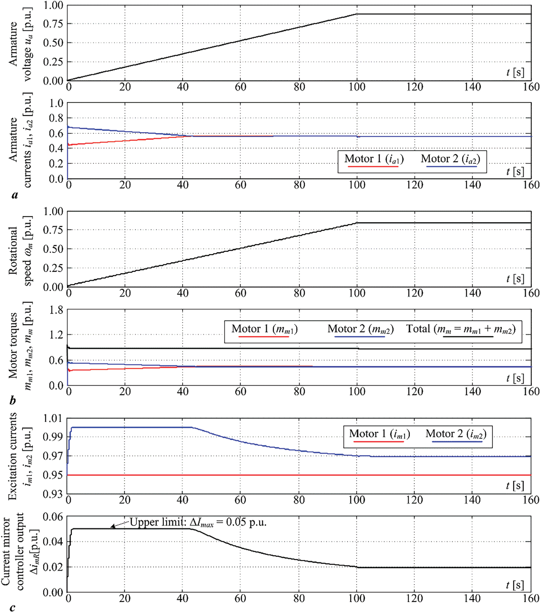
Figure 12: Dual DC drive simulation results with “current mirror” control turned on: armature voltage and current responses (a), drive rotational speed and torque responses (b), and excitation current system responses (c)
To summarize, when the “current mirror” control system is not employed, there is a significant mismatch of armature currents between the individual DC machines, which is caused by the mismatch of individual DC machine armature resistances, as previously illustrated in Fig. 8a. On the other hand, when the armature the “current mirror” PI controller is employed, it effectively equalizes the armature currents of individual DC motors in the presence of notable armature resistance mismatch. The particular simulation scenarios shown in Figs. 11 and 12, wherein one of the DC machines is characterized by 50% higher armature resistance compared to the other DC machine characterized by nominal-valued armature resistance, clearly demonstrates that the armature current of the DC machine whose excitation is controlled by the “current mirror” PI controller within the closed feedback loop can be matched to the exact value of the armature current of the parallel-connected DC machine that is operated by means of armature voltage only.
The proposed current mirror control system has been tested on a commercial deep drilling rig used to produce a geothermal well near Legrad, Republic of Croatia (see, e.g., [36]), which is shown in Fig. 13a. The rig is equipped with dual DC machine mud pump drives, shown in Fig. 13b. Field testing and commissioning were conducted over a 24 h period, during which the control system hardware was prepared and a control software upgrade including the developed “current mirror” PI controller has been downloaded to the motor power converter control unit and successfully tested. As per agreement with the industry partners, the final 30-min commissioning test has been approved for dissemination, and the results of this final commissioning test are shown in Fig. 14.

Figure 13: Photographs of a deep drilling rig (a) and mud pump drive (b)

Figure 14: Experimental results obtained during deep drilling rig field tests: armature voltage and current responses (a), and rotational speed and excitation current responses (b)
The results of the 30-min-long commissioning test with “current mirror” control system turned on are shown in Fig. 14. The results were obtained for a gradual startup of the dual DC machine pump drive with both machines connected to the common armature voltage (top plot in Fig. 14a), which results in gradual increase of motor armature currents, and drive rotational speed (bottom plot in Fig. 14a and top plot in Fig. 14b). Armature currents of both DC motors are kept at near identical values by the action of “current mirror” PI controller acting upon the motor 2 excitation current. It continuously adjusts the motor 2 excitation current during the mud pump electrical drive operation to compensate for inevitable slow variations of armature resistances due to both motors warming up from the “cold” state (bottom plot in Fig. 14b).
Thus, the main perceived benefits of the proposed “current mirror” control system manifest as: (i) rather fast equalization of armature currents of individual DC motors operating in parallel on the common armature voltage source (main high-power thyristor power converter), and (ii) continuous adjustment of the armature current of the controlled DC motor, so that it matches the armature current of the DC motor which is only open-loop controlled by means of armature voltage. In this way, the dual DC electrical drive can adapt to the inevitable armature resistance changes due to heat losses-related temperature increase, and, thus, provide balanced electrical load distribution between individual DC machines.
The paper has presented the design methodology for the development of a retrofitting solution aimed at armature current balancing (equalization) control for a mud pump dual DC motor electrical drive on a deep drilling rig. In this “legacy” application, the individual DC machine armature circuits are connected in parallel and supplied from a common armature power converter, while their excitation circuits are supplied separately using their respective current-controlled excitation (field) power converters. For the design and simulation analysis of the armature current equalization control system using excitation current control only (the so-called armature “current mirror” control system), a suitable model of dual electrical machine DC drive and mud pump load has been derived. The electrical drive model has been subsequently linearized and simplified for the sake of linear feedback PI controller design, whose tuning has been based on the so-called symmetrical optimum criterion.
The proposed “current mirror” control system has been verified through simulations and experimentally. Simulation results have shown that without the “current mirror” control system, the dual DC motor pump drive with DC motor armatures connected in parallel can exhibit a notable discrepancy in armature currents if their armature resistances do not match. On the other hand, when the proposed “current mirror” control system is turned on so it can adjust the excitation current of one of the motors, it can effectively and rather quickly equalize the armature currents of both motors and, consequently, equalize the developed torques of individual motors. In this way both the electrical and mechanical load of individual motors is effectively balanced. Finally, field tests carried out on the commercial deep drilling rig have confirmed that the proposed armature current mirror control system results in consistent and continuous adjustment of the excitation current of one of the motors, thus balancing the armature currents of DC motors within the dual DC motor mud pump electrical drive.
Future work is going to be directed towards developing suitable strategies for the improvement of energy efficiency and the environmental friendliness of the drilling process. These may include the utilization of high efficiency vector-controlled AC electrical drives and control system configurations suitable for dual electrical machine-based pump drive such as the master-slave in its basic speed/torque reference following and dynamic load sharing (droop control) configurations, or the more complex centralized control approaches.
Acknowledgement: Technical and organizational support during field tests provided by Zdravko Kučan, ing. and Anton Lisac, dipl. ing. (retired) from Nev-El Ltd., and Josip Mišković, dipl. ing. (retired, formerly affiliated with CROSCO—Integrated Drilling & Well Services Co.) is gratefully acknowledged herein.
Funding Statement: It is gratefully acknowledged that this research has been supported by the European Regional Development Fund (ERDF) through the grant KK.01.1.1.07.0031 “Prognostic maintenance of industrial rotary equipment based on machine learning and IoT technology in interaction with information systems”.
Author Contributions: The authors confirm contribution to the paper as follows: study conception and design: Danijel Pavković, Mihael Cipek; data collection: Danijel Pavković; analysis and interpretation of results: Danijel Pavković, Pietro Kristović, Dragutin Lisjak; draft manuscript preparation: Danijel Pavković, Pietro Kristović, Mihael Cipek. All authors reviewed the results and approved the final version of the manuscript.
Availability of Data and Materials: Due to the nature of this research, participants of this study did not agree for their data to be shared publicly, so supporting data is not available.
Ethics Approval: Not applicable. This study did not involve humans or animals.
Conflicts of Interest: The authors declare no conflicts of interest to report regarding the present study.
Abbreviations
| AC | Alternating current |
| AC/DC | Alternating current-to-direct current |
| bar | Pressure measurement unit (105 Pascals) |
| CSI | Current-source inverter |
| DC | Direct current |
| det() | Matrix determinant |
| EMF | (Counter) electromotive force |
| GE752 | High-power/high-torque motor under investigation |
| kNm | Kilo-Newton-meter (torque measurement unit) |
| L1, L2, L3 | Voltage lines in the three-phase electrical grid |
| M | Motor (electric) |
| M1, M2 | Motors 1 and 2, respectively |
| MW | Mega-Watt |
| PI | Proportional-integral (controller) |
| p.u. | Per-unit value, i.e., variable normalized to its rated (nominal) value |
| RoP | Rate-of-Penetration |
| VSI | Voltage-source inverter |
| WoB | Weight-on-Bit |
| Variables | |
| e | DC electrical machine counter electromotive force (induced armature voltage) |
| e1, e2 | Motors 1 and 2 counter electromotive forces (induced armature voltages) |
| ia | DC electrical machine armature current |
| ia1, ia2 | Motors 1 and 2 armature currents |
| ia1f, ia2f | Motors 1 and 2 armature current low-pass filtered values |
| im, imR | DC electrical machine excitation current and its reference (target) value, respectively |
| im1, im2 | Motors 1 and 2 excitation currents |
| imR1, imR2 | Motors 1 and 2 excitation current references (target values) |
| mL, | Pump load torque and average load torque at the motor side |
| mm | DC electrical machine torque |
| mm1, mm2 | Motors 1 and 2 torque values |
| mtot | Total (overall) torque of the dual DC machine electrical drive |
| ua | Common armature voltage |
| Δe1, Δe2 | Motors 1 and 2 counter electromotive force small-magnitude perturbations |
| Δia1, Δia2 | Motors 1 and 2 armature current small-magnitude perturbations |
| Δia1f, Δia2f | Motors 1 and 2 armature filtered current small-magnitude perturbations |
| Δim1, Δim2 | Motors 1 and 2 excitation current small-magnitude perturbations |
| ΔimR1 | Motor 1 excitation current target perturbations |
| ΔimR2 | Motor 2 excitation current target perturbations (also PI controller output) |
| Δmm, Δ | Overall motor torque and load torque perturbations |
| Δωm | Motor speed perturbations |
| Φm | DC motor magnetic field flux |
| Φm(im1,2) | Field flux vs. excitation current characteristic for motors 1 and 2 |
| Φm1,2 | Motors 1 and 2 magnetic field fluxes |
| ωm | Dual motor drive rotational speed |
| ωss | Dual motor drive rotational speed steady state value |
| Parameters | |
| a | The free parameter in the symmetrical optimum tuning procedure |
| A | System matrix of the closed-loop dual DC electrical drive control system |
| cfek | Equivalent drill-string pipeline stiffness |
| D | Pump cylinder inner diameter |
| ibelt | Belt drive transmission ratio |
| ig | Gearbox transmission ratio |
| I | Identity matrix (diagonal matrix with ones at the main diagonal) |
| Ia, Im | Armature current and excitation (magnetizing) current steady-state values |
| Ian, Imn | Armature current and excitation current nominal (rated) values |
| Ia1, Ia2 | Motors 1 and 2 armature current steady-state values |
| Im1, Im2 | Motors 1 and 2 excitation current steady-state values |
| ImR1, ImR2 | Motors 1 and 2 excitation current reference steady-state values |
| Jcs | Crankshaft moment of inertia (total value) |
| Jds | Driveshaft moment of inertia |
| Jm | Motor moment of inertia (rotor inertia) |
| Jtot | Total inertia referred to the transmission input (motor side) |
| Ke, Km | DC motor electromotive force constant and torque constant, respectively |
| Kmp | Borehole pressure vs. load torque proportionality coefficient (gain) |
| KΦ | Equivalent gain |
| L | Length of the connecting rod |
| La, Ra | DC electrical machine armature inductance and resistance, respectively |
| La1, La2 | Motors 1 and 2 armature inductances |
| p0, p1 | Atmospheric pressure and pressure within the drill-string pipeline |
| QVds | Drill-string (input) volumetric fluid flow rate and |
| Qdr | Borehole (return) volumetric fluid flow rate |
| r | Radius of the crankshaft |
| Ra1, Ra2 | Motors 1 and 2 armature resistances |
| Tef | Armature current measurement filter equivalent time constant |
| Tem | Magnetizing current closed-loop system equivalent time constant |
| TΣ | Equivalent lag time constant |
| Vds | Drill-string volume |
| β | Drilling fluid (mud) compressibility |
| ±Δimax | Current mirror PI controller limit values |
| ΔpDr | Borehole (return) pressure drop |
| λ | Vector of eigenvalues of the closed loop system |
| λi | ith eigenvalue of the closed loop system (i = 1, … , 8) |
| Φm(Im1,2) | Steady-state field flux for excitation current steady-state value Im1(Im2) |
| Φm(Im1,2)/im1,2 | Field flux curve gradient at steady-state excitation current Im1,2 |
| ω01, ω02 | Motors 1 and 2 idle speed values |
References
1. Li J, Zhu T, Li F, Wang D, Bu X, Wang L. Performance characteristics of geothermal single well for building heating. Energy Eng. 2021;118(3):517–34. doi:10.32604/EE.2021.014464. [Google Scholar] [CrossRef]
2. Li H, Zhao X, Huang S, Wang L, Chen J. Thermo-economic performance of geothermal driven high-temperature flash tank vapor injection heat pump system: a comparison study. Energy Eng. 2023;120(8):1817–35. doi:10.32604/ee.2023.027668. [Google Scholar] [CrossRef]
3. Xu W, Zhu Y, Wei Y, Su Y, Xu Y, Ji H, et al. Prediction model of drilling costs for ultra-deep wells based on GA-BP neural network. Energy Eng. 2023;120(7):1701–15. doi:10.32604/ee.2023.027703. [Google Scholar] [CrossRef]
4. Epelle EI, Gerogiorgis DI. A review of technological advances and open challenges for oil and gas drilling systems engineering. AlChE J. 2020;66(4):e16842. doi:10.1002/aic.16842. [Google Scholar] [CrossRef]
5. Olukanni DO, Ugwu NC. Mud rotary drilling in Southern Nigeria: potential adverse effects of its by-products on the environment. Int J Water Resour Environ Eng. 2013;5(5):262–71. doi:10.5897/IJWREE12.101. [Google Scholar] [CrossRef]
6. Zamora M, Broussard PN, Stephens MP. The top 10 mud-related concerns in deepwater drilling operations. In: SPE International Petroleum Conference and Exhibition in Mexico; 2000 Feb 1–3; Villahermosa, Mexico. SPE-59019-MS. doi:10.2118/59019-ms. [Google Scholar] [CrossRef]
7. Ivanova TN, Biały W, Korshunov AI, Jura J, Kaczmarczyk K, Turczyński K. Increasing energy efficiency in well drilling. Energies. 2022;15(5):1865. doi:10.3390/en15051865. [Google Scholar] [CrossRef]
8. Di Carlo F, Mazzuto G, Bevilacqua M, Ciarapica FE. Retrofitting a process plant in an Industry 4.0 perspective for improving safety and maintenance performance. Sustainability. 2021;13(2):646. doi:10.3390/su13020646. [Google Scholar] [CrossRef]
9. Pavković D. Current trends in oil drilling systems r&d with emphasis on croatian oil drilling sector—a review. In: Proceeding 9th International Conference Management of Technology—Step to Sustainable Production (MOTSP 2017); 2017 Apr 5−7; Dubrovnik, Croatia. [Google Scholar]
10. Kaiser MJ, Snyder BF. The five offshore drilling rig markets. Vol 8. In: Kaiser MJ, SnyderBF, editors. The offshore drilling industry and rig construction in the Gulf of Mexico, Lecture Notes in Energy. London, UK: Springer-Verlag; 2013. doi:10.1007/978-1-4471-5152-4_2. [Google Scholar] [CrossRef]
11. Lyons WC, Plisga GJ, Lorenz MDeditors. Drilling and well completions. In: Standard handbook of petroleum and natural gas engineering. 3rd ed. Houston, TX, USA: Gulf Publishing Company; 1996. p. 499–1373. [Google Scholar]
12. Nygaard G, Gjeraldstveit H, Skjæveland O. Evaluation of automated drilling technologies developed for petroleum drilling and their potential when drilling geothermal wells. In: Proceeding World Geothermal Congress; 2010; Bali, Indonesia [Internet]. [cited 2024 Nov 10]. Available from: https://www.lovegeothermal.org/cpdb/record_detail.php?id=6372. [Google Scholar]
13. Fallah A, Gu Q, Chen D, Ashok P, van Oort E, Holmes M. Globally scalable geothermal energy production through managed pressure operation control of deep closed-loop well systems. Energy Convers Manag. 2021;236(2):114056. doi:10.1016/j.enconman.2021.114056. [Google Scholar] [CrossRef]
14. Stemmler H. High-power industrial drives. Proc IEEE. 1994;82(8):1266–86. doi:10.1109/5.301688. [Google Scholar] [CrossRef]
15. Verma M, Dick B, Phares D, Bondy S. Bringing new life to high-capacity systems: modernization of legacy adjustable-speed drives. IEEE Ind Appl Mag. 2013;19(6):66–74. doi:10.1109/MIAS.2012.2215997. [Google Scholar] [CrossRef]
16. Rodriguez C, Amaratunga GAJ. Long-lifetime power inverter for photovoltaic AC modules. IEEE Trans Ind Electron. 2008;55(7):2593–601. doi:10.1109/TIE.2008.922401. [Google Scholar] [CrossRef]
17. Silvestre CA, Nicoletti PH, Marcelino MA. Retrofitting industrial in electrical motor type: a matter of energy efficiency and reduction of maintenance. Sci Res Essays. 2014;9(21):906–23. doi:10.5897/SRE2013.5784. [Google Scholar] [CrossRef]
18. Jansen JD, van den Steen L. Active damping of self-excited torsional vibrations in oil well drillstrings. J Sound Vib. 1995;179(4):647–68. doi:10.1006/jsvi.1995.0042. [Google Scholar] [CrossRef]
19. Cipek M, Pavković D, Benić J, Šitum Ž. Mud pump pressure pulsation control systems. In: Proceeding International Conference on Fluid Power 2023; 2023 Sep. 20–21; Maribor, Slovenia; p. 20–1. [Google Scholar]
20. Soft Pump System Technical Data Sheet. Bentec GmbH drilling & oilfield systems; 2016. [Internet]. [cited 2024 Nov 10]. Available from: https://www.bentec.com/pdf_files/flyer-soft-pump-system-en_323_1.pdf. [Google Scholar]
21. CROSCO EMSCO 605 2000 HP Drilling Rig Data Sheet. CROSCO—Integrated Drilling & Well Services Co. (2018); 2018. [Internet]. [cited 2024 Nov 10]. Available from: https://crosco.com/wp-content/uploads/2018/01/emsco605.pdf. [Google Scholar]
22. SINAMICS DCM Operating Instructions. Siemens AG; 2023. [Internet]. [cited 2024 Nov 10]. Available from: https://cache.industry.siemens.com/dl/files/291/109825291/att_1157597/v1/SINAMICS_DCM_DC_Converter_en-US.pdf. [Google Scholar]
23. Bezold KH, Forster J, Zander H. Thyristor converters for traction DC motor drives. IEEE Trans Ind Applicat. 1973;IA-9(5):612–7. doi:10.1109/TIA.1973.349948. [Google Scholar] [CrossRef]
24. Schröder D. Elektrische antriebe-regelung von antriebssystemen. 3rd ed. Berlin, Germany: Springer-Verlag; 2007. [Google Scholar]
25. Barkas DA, Ioannidis GC, Psomopoulos CS, Kaminaris SD, Vokas GA. Brushed DC motor drives for industrial and automobile applications with emphasis on control techniques: a comprehensive review. Electronics. 2020;9(6):887. doi:10.3390/electronics9060887. [Google Scholar] [CrossRef]
26. Leonhard W. Control of electrical drives. 2nd ed. Berlin, Germany: Springer-Verlag; 1996. [Google Scholar]
27. Matsuse K, Matsuhashi D. New technical trends on adjustable speed AC motor drives. Chin J Electr Eng. 2017;3(1):1–9. doi:10.23919/CJEE.2017.7961316. [Google Scholar] [CrossRef]
28. Triplex Mud Pumps Technical Brochure. National oilwell varco; 2006. [Internet]. [cited 2024 Nov 10]. Available from: https://cdn.energydais.com/media/files/company/products/F_and_FD_Series_Triplex_Mud_Pumps_Brochure.pdf. [Google Scholar]
29. Vertical Drilling Motor Type GE752 Maintenance Manual. General Electric Co.; 2024. [Internet]. [cited 2024 Nov 10]. Available from: https://www.gulfelectroquip.com/wp-geq/wp-content/uploads/Stnd752ManLR1.pdf. [Google Scholar]
30. Ekanayake J, Liyanage K, Wu J, Yokoyama A, Jenkins N. Smart grid—technology and applications. 1st ed. Chichester, UK: John Wiley and Sons, Ltd.; 2012. p. 187–203. doi:10.1002/9781119968696.ch9. [Google Scholar] [CrossRef]
31. Sen PC, Doradla SR. Symmetrical and extinction angle control of solid-state series motor drive. IEEE Trans Ind Electron Contr Instrum. 1976;IECI-23(1):31–8. doi:10.1109/TIECI.1976.351344. [Google Scholar] [CrossRef]
32. Plavac F, Pavković D, Trstenjak M, Cipek M, Benić J, Lisjak D. Speed control of a series DC drive for drilling applications with vibration damping torque feedback loop. In: Proceeding 14th International Scientific Conference MMA 2021—Flexible Technologies; 2021; Novi Sad, Serbia. p. 185–8. [Google Scholar]
33. Stone GC. Condition monitoring and diagnostics of motor and Stator windings—a review. IEEE Trans Dielectr Electr Insul. 2013;20(6):2073–80. doi:10.1109/TDEI.2013.6678855. [Google Scholar] [CrossRef]
34. Isermann R. Digital control systems. Berlin, Germany: Springer-Verlag; 1989. [Google Scholar]
35. Kreysig E. Advanced engineering mathematics. 8th ed. New York, NY, USA: John Wiley & Sons; 1999. [Google Scholar]
36. Tuschl M, Kurevija T, Krpan M, Macenić M. Overview of the current activities related to deep geothermal energy utilisation in the Republic of Croatia. Clean Technol Environ Policy. 2022;24(10):3003–31. doi:10.1007/s10098-022-02383-1. [Google Scholar] [CrossRef]
Cite This Article
 Copyright © 2025 The Author(s). Published by Tech Science Press.
This work is licensed under a Creative Commons Attribution 4.0 International License , which permits unrestricted use, distribution, and reproduction in any medium, provided the original work is properly cited.
 Downloads
 Citation Tools