
 Submit a Paper
 Propose a Special lssue
 Open Access
ARTICLE

ESVG Adaptive Control Method for Fast Frequency Support of Wind Farm
1 State Grid Jilin Electric Power Co., Ltd., Changchun, 130021, China
2 State Grid Jilin Electric Power Research Institute, Changchun, 130021, China
3 School of Electrical Engineering, Northeast Electric Power University, Jilin, 132012, China
* Corresponding Author: Jiayang Zhang. Email:
(This article belongs to the Special Issue: AI-application in Wind Energy Development and Utilization)
Energy Engineering 2025, 122(5), 1863-1885. https://doi.org/10.32604/ee.2025.061940
Received 06 December 2024; Accepted 19 February 2025; Issue published 25 April 2025
 View Full Text
 Download PDF
Abstract
Aiming at the problems of large fluctuation of output active power and poor control performance in the process of frequency support of an energy-storage-type static-var-generator (ESVG), the adaptive adjustment control method for its active-loop parameters is used to realize the wind-farm frequency support, which has become the current research hotspot. Taking the ESVG with a supercapacitor on the DC side as the research object, the influence trend of the change of virtual rotation inertia and virtual damping coefficient on its virtual angular velocity and power angle is analyzed. Then, the constraint relationship between the equivalent virtual inertia time constant of the supercapacitor and the virtual rotation inertia of the ESVG is clarified. Then, combined with the second-order response characteristics of the ESVG power control loop, the selection principles of the frequency modulation coefficient, the virtual rotation inertia, and the virtual damping coefficient are determined. An ESVG adjustment control method, considering the adaptive adjustment of the active loop parameters of the supercapacitor equivalent inertia, is proposed. While ensuring the frequency support capability of the ESVG, the fluctuation degree of its output active power and the virtual angular velocity are suppressed, and the proposed adjustment method also improves the stability of the ESVG control system and the frequency support capability for the wind farm. Finally, the simulation verifies the correctness of the theoretical analysis and the effectiveness of the proposed strategy.Keywords
With the increasing proportion of renewable generation represented by wind power, conventional power systems gradually show low inertia, low damping, and strength weakening, which is so serious as to threaten the safe and stable operation of the system. Therefore, relevant standards stipulate that renewable generators must retain a certain inertia reserve and the ability to participate in frequency-inertia support [1].
To enhance the inertia reserve and frequency stability in the wind power system, various improvement strategies have been proposed, including but not limited to wind turbine power self-synchronization control transformation [2–5], the installation of energy storage devices in back-to-back converters’ DC link of wind turbines, the improvement of control strategies [6] and the transformation of energy storage station [7,8]. In 2022, the relevant research showed that the supercapacitors in the back-to-back converter DC link of the wind turbine can effectively support wind power system frequency [9], but the installation of excessive large-capacity supercapacitors contradicts economic requirements in the wind farm. In 2024, Huang et al. pointed out that if excessive renewable generators are transformed into grid-forming control, they will face problems such as inter-machine circulation and power oscillation [10]. In the same year, Siemens Gamesa, Univ Strathclyde, and Tech Univ Denmark all proposed transforming the grid-side converter of the direct-drive wind turbine into the virtual synchronous generator (VSG) control. The active power loop combined with droop control can support the system’s inertia by releasing the mechanical energy of the wind turbine rotor [11,12], providing additional inertia support for the wind power system. To improve the utilization rate of wind power, energy storage stations gradually begin to be built to enhance the wind power system’s voltage stability and frequency regulation. However, the geographical location of wind farms is quite different, so energy storage power stations are unsuitable for wind farms in hilly and mountainous areas. At the same time, its construction investment and maintenance costs are too high, and the return on investment is relatively low, which limits its large-scale application [13].
In view of the above shortcomings, in January 2023, Shanghai Jiao Tong Univ and China Sieyuan proposed to transform the self-provided grid following Static Var Generator (SVG) in the wind farm into Grid Forming Energy Storage Type Static Var Generator (Hereinafter referred to as ESVG) in the weak power grid. The combination of supercapacitors and its chain topology can flexibly support the system frequency and effectively avoid the problem of multi-machine coordinated control in wind farms [14]. However, the active loop parameters in the grid forming control significantly influence the dynamic stability of the system. Improper parameter setting will increase the negative damping effect of the VSG control system and may induce low-frequency oscillation [15–17]. In recent years, artificial intelligence (AI) technology has developed rapidly. Now scholars have established a database for off-line training of neural networks. Online identification and optimization are carried out according to the scene of the grid converter [18,19]. However, scenes with high contingency requirements have high requirements for real-time control strategies, and the application of AI technology is limited.
Aiming at this problem, reference [20] pointed out that when the VSG output power suddenly changes, the VSG power fluctuation can be reduced by adaptively adjusting the virtual rotation inertia and virtual damping coefficient, improving the system transient regulation process.
Although ESVG can provide active power frequency and reactive power voltage support, the correlational research has just started. In addition, the construction of adaptive adjustment strategies for key parameters of active control loop and the theoretical analysis of frequency support dynamic response performance are still lacking. Therefore, the paper studies the adaptive control strategy for suppressing ESVG active output fluctuation and virtual angular velocity change. The main innovations are as follows:
(1) By combining the swing characteristics of synchronous generators with the charging and discharging laws of supercapacitors, the influence of ESVG’s active loop parameters on its power angle characteristics is discussed, and the restriction principle of the supercapacitors’ capacitance on the virtual rotation inertia and virtual damping coefficient of the ESVG is also clarified.
(2) An ESVG control adjustment strategy based on adaptive adjustment of active loop parameters is constructed. By dynamically adjusting the frequency modulation coefficient, virtual rotation inertia, and virtual damping coefficient, the virtual angular velocity and power angle change are reduced, and the active power overshoot of ESVG output is suppressed under the wind power system’s frequency fluctuation condition. At the same time, the adjustment time is shortened.
2 Wind Power System Structure and Control Strategy
In the wind power system, the fluctuation of wind turbine output caused by wind variation, load switching, and other factors is the fundamental reason for the active power output change of ESVG. After transforming the conventional grid following SVG into a grid-forming one, it utilizes the fast power output characteristics of supercapacitors to simulate the dynamic operation process of the synchronous generator’s rotor quickly.
2.1 Structure and Control Strategy of ESVG
Taking a wind farm in Northeast China as the application scenario, the topology structure of wind turbines and ESVG is shown in Fig. 1a, where Xg is the internal impedances of synchronous generator SM. Lf is the grid-connected filter inductor for ESVG. Ug is the grid connected voltage of ESVG. Ig is ESVG compensation current. The synchronous generator is connected to the 220 kV busbar through a transformer and a 5 km transmission line.
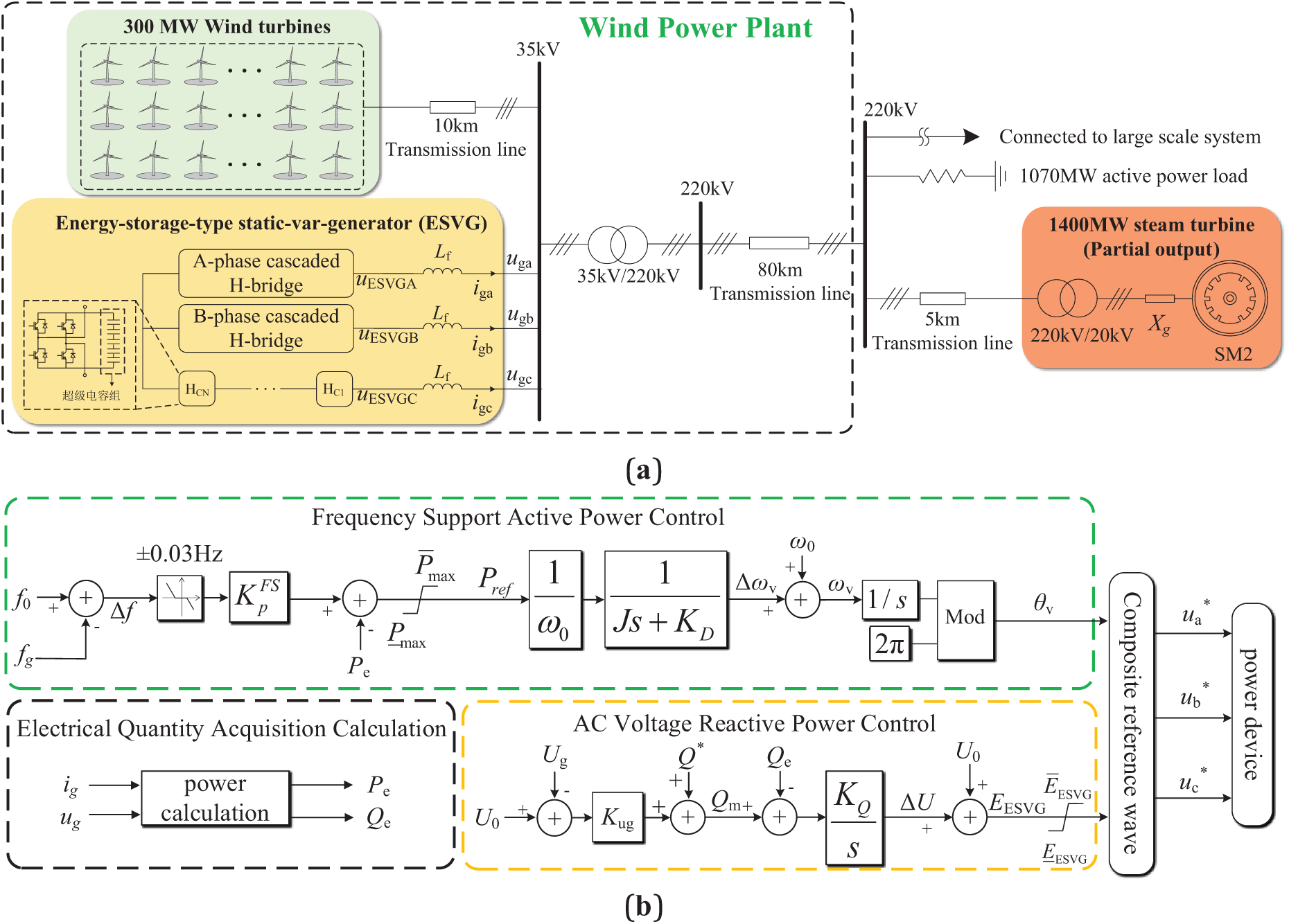
Figure 1: Schematic diagram of wind power system with ESVG. (a) Wind power system grid structure diagram; (b) ESVG control structure diagram
2.2 Virtual Synchronous Control Strategy of ESVG
The ESVG control structure with direct amplitude and phase control is shown in Fig. 1b. In the ESVG active control loop, f0 and fg are the power frequency and the actual system frequency, respectively, and Δf represents the frequency fluctuation of the wind power regional system.
In the AC voltage-reactive power control loop and ESVG electrical topology, U0, UESVG, and ΔU are the ESVG outlet voltage, the rated phase voltage of the PCC node, and the virtual excitation electromotive force adjustment value, respectively. After obtaining the reactive power adjustment value with the voltage adjustment coefficient Kug, it is summed with the grid-connected reactive power reference Q* and subtracted from the output reactive power of ESVG Qe. After the obtained difference is integrated by the coefficient KQ, the PCC phase voltage adjustment value ΔU is obtained and summed with Ug to obtain the virtual excitation electromotive force EESVG. The grid-connected power of ESVG is calculated according to the current output and PCC voltage. The virtual phase of ESVG can be obtained by an active power loop, combined with EESVG, and the virtual internal potential VPCC(
where Te is the virtual electromagnetic torque of ESVG, Td is the virtual damping torque of ESVG, and J is the virtual rotation inertia of ESVG. The virtual internal potential Q-V equation of ESVG is shown in Eq. (2).
3 The Influence of Active Loop Parameters on the Power Angle Characteristics of ESVG
3.1 ESVG Power Angle Characteristics
To simplify the description of the transient stability of ESVG, the dynamic response process of virtual impedance and current inner loop are ignored. The system in Fig. 1 is equivalent to an ESVG single-machine infinite bus system. The output voltage of ESVG is
where X is the impendence of Z. Rf, and Lf are ESVG filter reactance and parasitic resistance. Rg and Lg are the grid impedance. Due to ESVG being directly connected in parallel with the 35 kV high voltage bus, the resistance of the filter in ESVG can be omitted [21,22]. ESVG does not require virtual impedance for current limitations without considering fault conditions. The output power of ESVG is expressed as
When the wind power system usually operates, ESVG only needs to output reactive power to the wind power system, so ESVG grid-connected active command Pref is 0. To ensure that Qe varies with Qm, the reactive power deviation is integrated to obtain EESVG. To respond rapidly to its frequency requirements, its own time constant τ = KQ/KD is usually small, and the change of EESVG can be ignored [23,24]. Eq. (3) can be reasonably degenerated into a quasi-steady-state equation, according to Eqs. (1)–(4), the second-order differential equation of ESVG control system is obtained.
Setting the state variable
3.2 ESVG Power Angle Stability
Combined with the analysis of Reference [25], the imbalance between the reference value of the active power output of ESVG and the actual one is the internal cause of VSG transient angle instability. Therefore, in the virtual swing equation, J, KD, and system frequency fluctuation Δf are primary research variables. According to the second-order differential equations of the system shown in Eq. (6), the phase space trajectory of ESVG is drawn to observe the influence of each sensitive parameter on the electromechanical transient stability of ESVG.
3.2.1 The Influence of Droop Coefficient KD
Set J = 0.3 × 10⁴ k·m2 and Δf = −0.1 Hz without changing the system’s operating state. At the same time, the range of KD is 8 × 10⁴~8 × 10⁵ N·s/m, and its influence on δ is shown in Fig. 2a. From Fig. 2a, it can be seen that with the increase of KD, the variation of δ decreases, which is conducive to transient power angle stability. However, excessive virtual damping coefficient will lead to a more tremendous change in Δω of ESVG, and reduce its frequency support ability. The same is true of time-domain changes of δ and Δω. Similarly, when Δf = 0.1 Hz, the same analysis conclusion can be obtained. The result is shown in Fig. 2b.
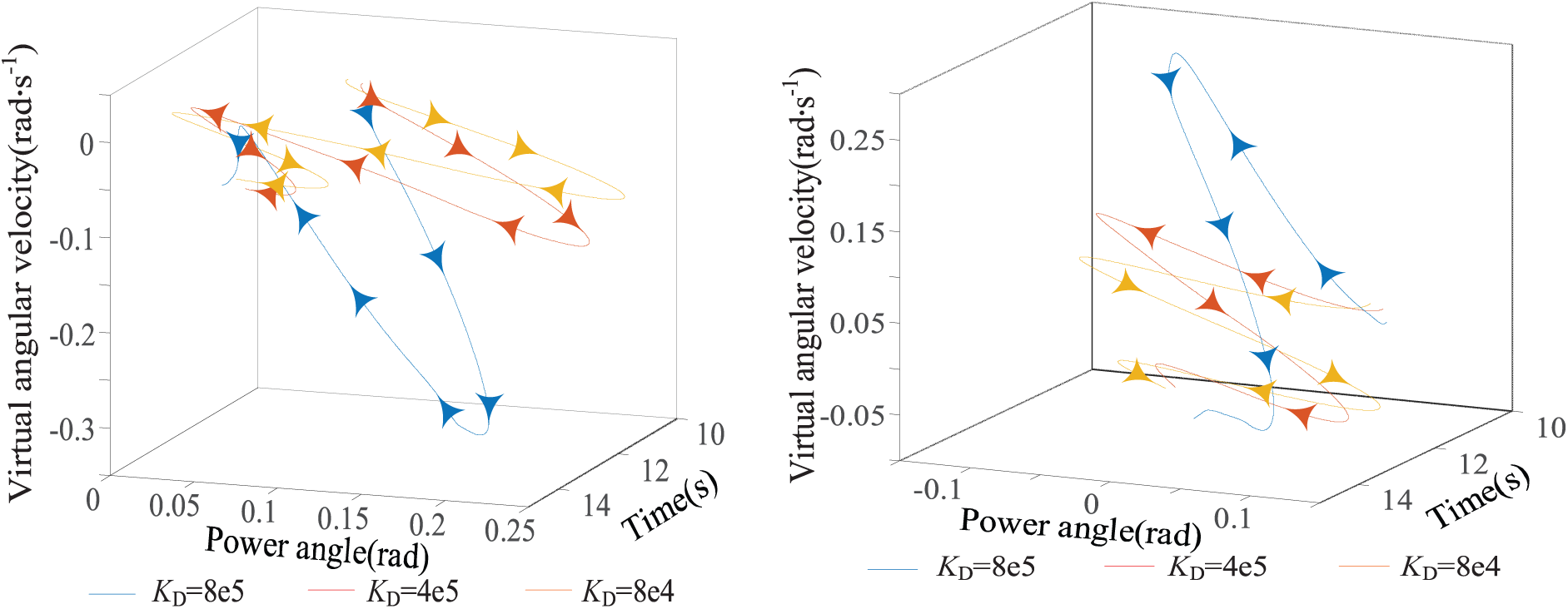
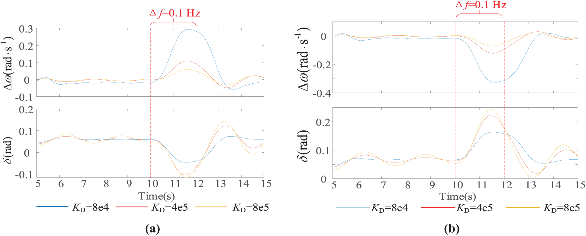
Figure 2: Trend of δ variation when KD changes. (a) Δf = −0.1 Hz; (b) Δf = 0.1 Hz
3.2.2 The Influence of Virtual Inertia Coefficient J
Set KD = 2.7 × 10⁵ N·s/m and Δf = −0.1 Hz without changing the system’s operating state. At the same time, the range J is 1 × 10⁴~13 × 104 k·m2, and its influence on δ is shown in Fig. 3a. As shown in Fig. 3a, with the increase of J, the motion trajectory in phase space expands outward, and the operating state of ESVG gradually deviates from the original point. The range of power angle variation also increases continuously. Since J has the effect of maintaining the original state, when the output active power of the wind farm changes, the excessive J will lead to the adjustment time extension of δ during the transient period, which is not conducive to the rapid frequency stability of the system. The same is true of time-domain changes of δ and Δω. Similarly, when Δf = 0.1 Hz, the same conclusion can be obtained. The result is shown in Fig. 3b.
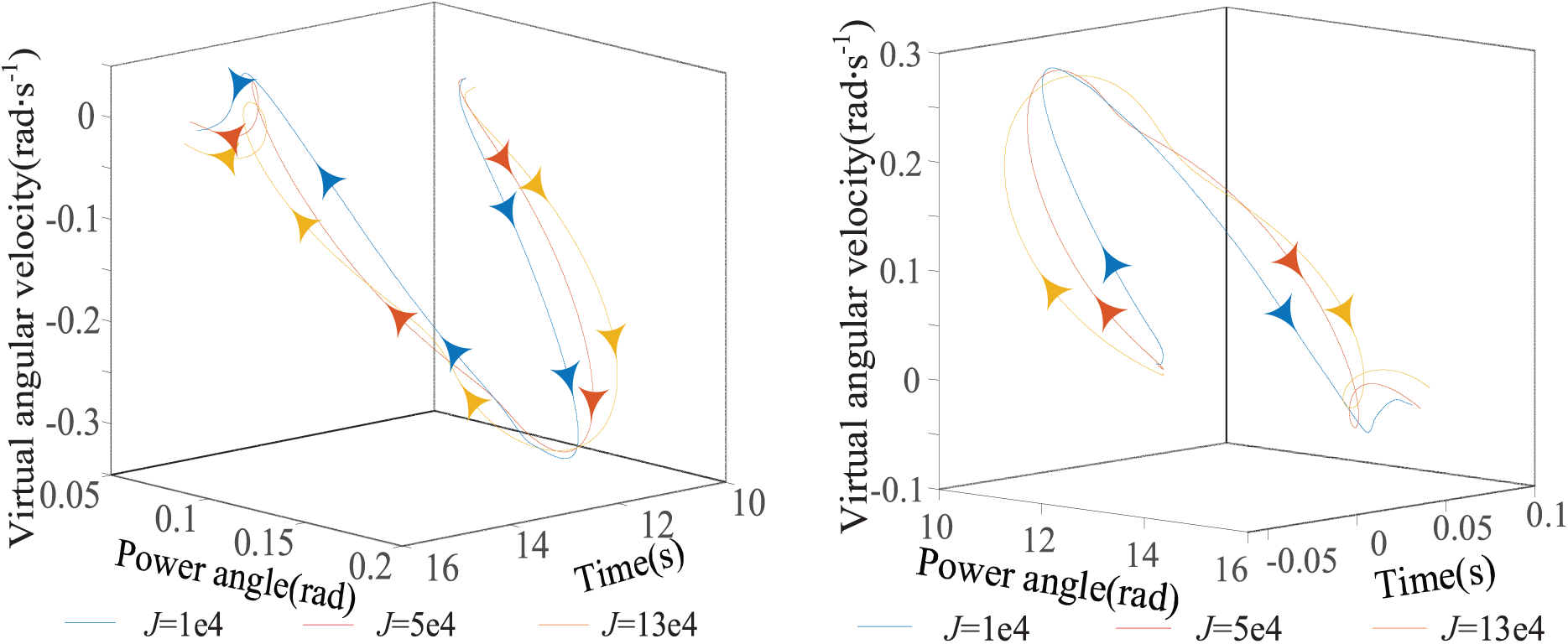
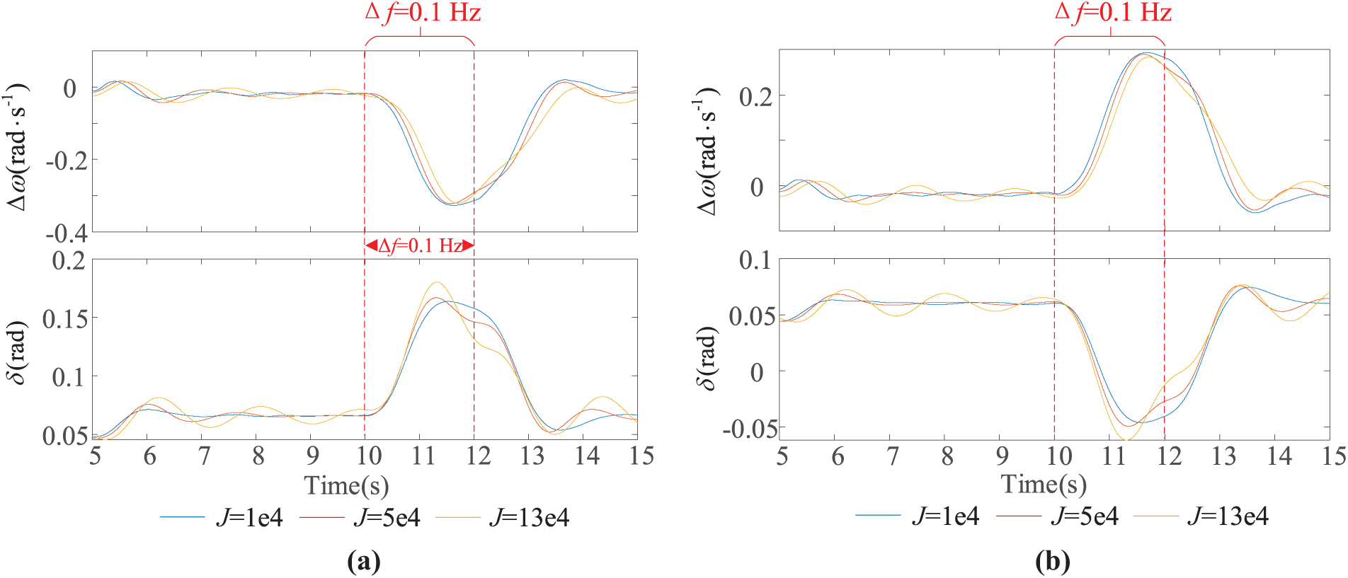
Figure 3: Phase space trajectory when J changes. (a) Δf = −0.1 Hz; (b) Δf = 0.1 Hz
Combined with Section 2.2, it can be seen that high KD is beneficial to improving the transient power angle stability of ESVG, but excessive KD is not conducive to the frequency stability of the system. High J is advantageous to the transient stability of the system, but excessive J will reduce the ability to regulate fast frequency. The above analysis indirectly proves the conclusion in [26] that there is a contradiction between frequency stability and transient stability of VSG.
Depending on the operating performance of the wind power system, if J and KD of ESVG can be flexibly adjusted, the dynamic response performance will be further improved.
4 Boundary Setting of ESVG’s Active Loop Parameters Considering the Influence of Supercapacitors
4.1 The Relationship between Supercapacitors and ESVG’s Inertia
Compared with conventional synchronous generators, large-scale access to new energy power generation devices shows the characteristics of low rotational inertia. According to the grid-forming control structure adopted by the ESVG in the first chapter and the rotational inertia of the synchronous generator shown in Eq. (4), the virtual synchronous control strategy can imitate the rotor motion of the synchronous generator. However, due to the lack of continuous power supply during energy release, ESVG cannot wholly reproduce the continuous output of the prime motor (Steam turbine) during the primary frequency modulation process but mainly imitates the process of converting the mechanical energy from the rotator shaft of the prime motor into electromagnetic energy.
where J′ represents the rotational inertia of the synchronous generator’s rotor. MT and ME represent the mechanical torque of the prime mover and the electromagnetic torque of the synchronous generator, respectively. WSG is the mechanical energy stored in synchronous generator’s rotor shaft at the rated speed. Ω0 represents the rated mechanical angular velocity of synchronous generator’s rotor. Cesc represents the equivalent capacitance of all supercapacitors in the chains of ESVG. Unlike the synchronous generator, there is no continuous power injection (no virtual mechanical torque) on the DC side of the ESVG. The equivalent virtual electromagnetic torque is formed only by the electrochemical energy WESVG stored in the supercapacitors. Although the energy stored in the above two is similar in the form of expression, ESVG is essentially different from the synchronous machine. Especially in terms of output voltage vector control, ESVG is insufficient.
Taking the frequency reduction condition of the wind power system as an example, the phase change of ESVG and system voltage is shown in Fig. 4. It is assumed that the J of ESVG is infinite. When the active power demand of the wind power system occurs, the α between ESVG and the system increases. However, excessive J results in a constant ESVG phase in a short period.
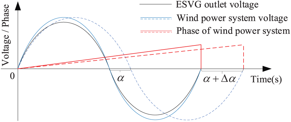
Figure 4: Relationship between ESVG and voltage phase of wind power system
As shown in Fig. 4, before the frequency of the wind power system decreases, the voltage amplitude and phase of the ESVG are basically identical to the wind power system. After the frequency of the wind power system decreases, excessive J will lead to rapid energy release from the ESVG supercapacitors. Due to the limited energy storage, the voltage of supercapacitors will continue to drop, thus affecting the reactive power compensation performance of ESVG.
4.2 The Constraint of Supercapacitor Capacitance on Virtual Rotation Inertia
Considering the influence of the number of cascaded submodules N on the equivalent capacitance of ESVG, the variation range of ESVG DC cluster voltage Udc is limited to 0.8~1.1 pu, and the available active power Pav of each phase can be expressed as Eq. (8).
According to Eq. (9), maintaining a constant N, if the capacitance of the supercapacitor in each submodule decreases, the overall equivalent capacitance will decrease. The voltage change rate dUdcj/dt and the variation of DC voltage will increase, which is not conducive to the stable operation of ESVG in the wind power fluctuation scenario. Based on the wind system model with ESVG, DC cluster voltage simulation results are shown in Fig. 5.
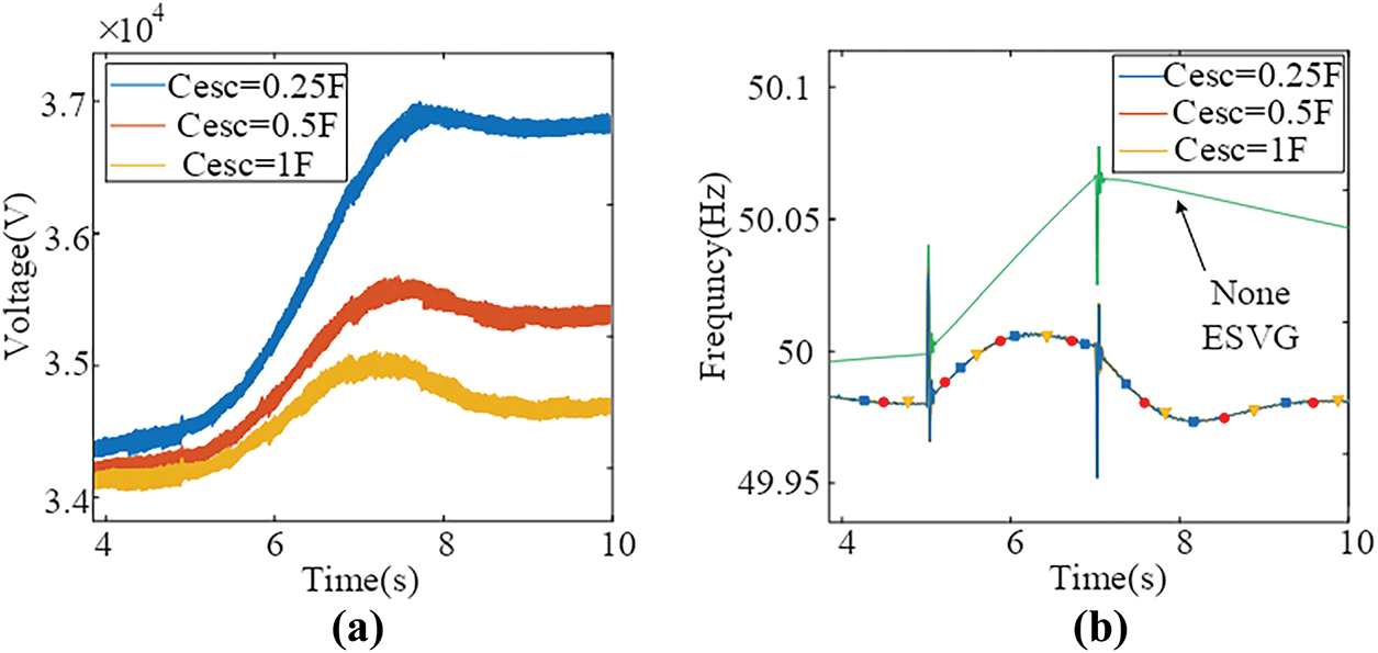
Figure 5: The influence of different Cesc on the frequency change of the system. (a) ESVG DC cluster voltage; (b) Wind power system frequency
Fig. 5 shows that during wind power fluctuation. However, ESVG can still effectively suppress system frequency changes, and the DC cluster voltage change intensifies with the decrease of individual capacitance, which is consistent with the former analysis in Eq. (9).
According to an actual wind farm in Northeast China, the capacity of an ESVG Sn = 50 MVA, the equivalent inertia time constant of supercapacitors 12 s ≤ Hesc ≤ 20 s, and the capacitance of a single supercapacitor can be expressed as
According to Eq. (9), it can be seen that the frequency fluctuation increases as is constant. To ensure the active-frequency support ability of ESVG, it is necessary to equip it with a larger supercapacitor capacitance. The increase in the capacitance of the supercapacitor will lead to an increase in Hesc. Although the adjustment time of the frequency is prolonged to some degree, the active-frequency support ability of the ESVG can be enhanced. Here, N = 10 and Ci = 1.5 F. The allowable fluctuation range of DC cluster voltage is 22.86 KV~31.43 KV (0.8~1.1 pu). From Eq. (10), the constraint range of ESVG’s J is 10,860~18,618 kg·m2.
4.3 Virtual Rotation Inertia and Virtual Damping Coefficient Tuning
The small signal model of the active power control loop of the ESVG in the frequency domain can be obtained by combining Eqs. (1)–(6), as shown in Fig. 6.
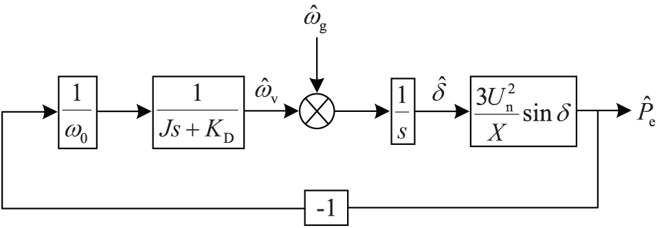
Figure 6: Small signal model of ESVG active power control loop
The active-inertia disturbance equation and frequency closed-loop transfer function of ESVG can be further obtained from Fig. 6 and can be expressed as
Un is the practical value of PCC phase voltage. Considering the demand for primary frequency regulation response of conventional synchronous generators, when the frequency of wind power systems fluctuates, the response time of the ESVG active power loop should be less than 100 ms to exert its fast active power regulation advantage. Combined with the active power control characteristics of ESVG, the natural oscillation angular frequency ωnf and damping ratio ξf of the active inertia response of ESVG can be obtained by Eq. (11).
When the frequency disturbance occurs in the wind power system, the ESVG control response can accelerate the response speed in the underdamped state in the initial reaction stage. To quickly eliminate ESVG control oscillations and reduce overshoot, choosing critical damping or overdamping is more scientific. Therefore, the value of J should be adapted to the frequent switching between underdamped and overdamped states during disturbance. At the same time, to ensure the stability of ESVG active-inertia closed-loop control, it is necessary to ensure that its characteristic roots are all negative values. Therefore, the boundary condition of ξf is written as follows:
When the ESVG responds to the system’s frequency demand, it cannot exceed its own maximum charge-discharge power, Pemax.
where
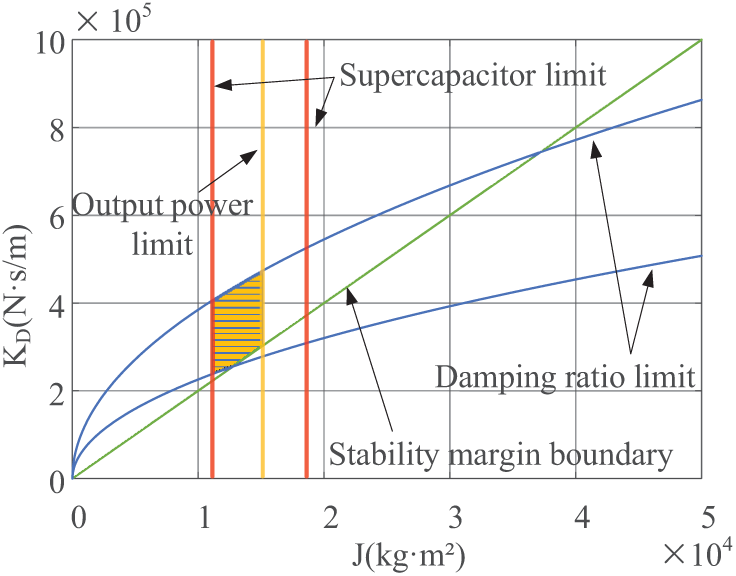
Figure 7: Feasible region of ESVG active loop parameters
The yellow shaded area in Fig. 7 represents the selection range of J and KD. After J is tuned, KD is tuned based on the relationship between the frequency variation of the wind power system and the active power output of ESVG.
The relationship between the frequency variation of the wind power system and the output power of the ESVG can be obtained from Eq. (11).
It is assumed that when the wind power system’s frequency change exceeds 0.03 Hz, the ESVG’s output active power equals Pemax.
Combined with the above J-KD feasible region, the initial values of J and KD are taken as 1.3 × 10⁴ kg·m2 and 2.5 × 10⁵, respectively.
5 Adjustment Strategy of ESVG Control Based on ALP
For the ESVG frequency support control structure shown in Fig. 1b,

Figure 8: ESVG active power control loop based on ALP
5.1 ESVG Power Operating Boundary
The essential condition for the stable operation of ESVG is that the output power does not exceed the steady-state power operating range. In the practical application process, ESVG can operate for 1 s with three times the rated active power, and the steady-state overload multiple km = 3 is set. Assuming Pe = Pref, the maximum operating power angle
The active and reactive power output from ESVG to the wind farm can be expressed as
Set
In addition, further constraints need to be set based on the operating range of ESVG’s DC side voltage mentioned in Section 4.2.
In summary, the stable output power operating range of ESVG is determined based on the following constraints:
Condition 1: Set the rated capacity of ESVG, combined with Formula (17) to calculate the possible ESVG power operating point. When
Condition 2: According to Eq. (18), determine whether the real and imaginary parts of the equation are equal at both ends. If not, exclude the operating point. On the contrary, ESVG can operate at that power point and further verification is required.
Condition 3: ESVG can operate stably if its DC voltage meets Eq. (19) during ESVG’s active frequency support period.
The power operating points that meet all the above conditions are drawn to form a stable power operating range of ESVG, as shown in Fig. 9.
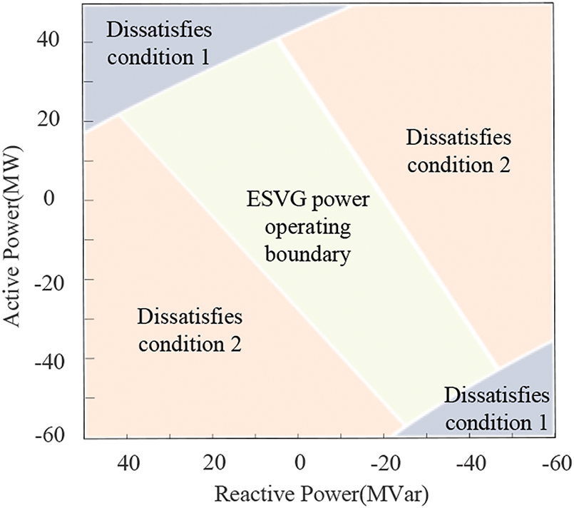
Figure 9: Stable power operating area of ESVG
The active power operation range of ESVG in Fig. 9 determines the active-frequency support capability of ESVG. The threshold limiting can adjust the output active power of ESVG in the range of
5.2 Adjustment Strategy of Frequency Modulation Coefficient Based on ESVG Active Power Limitation
If
In Eqs. (20) and (21), Δfmax and Δfmin are the upper and lower critical values of the frequency adjustment range of the ESVG frequency modulator, respectively, and set to ±0.2 Hz. [−0.03, 0.03] Hz is the dead zone of ESVG participating in the frequency modulation of the wind power system. Within this range, the frequency regulator does not work, and there is no active power exchange between ESVG and the wind power system, thereby avoiding frequent charging and discharging of supercapacitors. If Δf ∈ [−0.2, −0.03] ∪ [0.03, 0.2] Hz, the frequency modulator calculates Pref. When Pref exceeds the critical values of the frequency adjustment range, it is limited to the active power output threshold
5.3 Virtual Rotation Inertia and Virtual Damping Coefficient Adjustment Strategy
From the analysis of Section 2, it can be seen that ESVG’s Δωv characterizes the fluctuation degree of active power output during the frequency support process, which can be expressed as
From Eq. (22), it can be seen that J and KD are negatively correlated with the ESVG virtual angular velocity change rate dωv/dt and the angular velocity change amount Δωv, respectively. Active power overshooting can be suppressed by simultaneously reducing J and increasing KD. When dωv/dt > 0, a larger J can reduce the system overshoot to a certain extent, but it will prolong the adjustment time. When dωv/dt < 0, setting a smaller J can quickly stabilize the system, but the overshoot tends to increase. To alleviate this contradiction, in the process of adjusting J, when the change of ωv exceeds the adjustment threshold, KD should be increased to suppress the excessive |Δωv|. When dωv/dt > 0, ALP increases J to suppress overshoot and simultaneously increases KD, so the output power steadily reaches the command value. Based on the above analysis, as shown in the blue block of Fig. 8, the ALP control strategy of J and KD is designed as follows:
In Eqs. (23) and (24), J0 and KD0 are the initial values of ESVG’s J and KD (which can be obtained by combining with the plane diagram of J-KD feasible region in Fig. 6). Kj1, Kj2, and Kd are the virtual rotation inertia and damping adjustment coefficient, respectively. The frequency modulation range of ESVG is set to [−0.2, −0.03] Hz and [0.03, 0.2] Hz. The transfer function of the ESVG active control loop can be regarded as a type-II system. According to the system simulation parameters provided in Table 1, the virtual angular velocity oscillation curve of ESVG after a small disturbance is shown in Fig. 10.
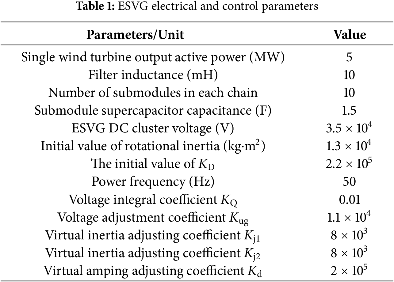
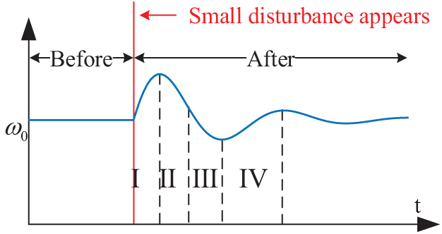
Figure 10: ESVG virtual angular velocity oscillation curve
According to the analysis of Eqs. (23) and (24) and Fig. 10, it can be seen that in the process of ESVG starting to respond to the active power demand of the system in stage I, its virtual phase is no longer consistent with the phase of the wind power system. At this point, |Δωv | increases and exceeds the dead zone, and KD will increase while J increases. After ωv reaches the peak, its change enters the second stage. At this time, |Δωv | will re-exceed the dead zone. The increase of KD and the decrease of J can shorten the oscillation time of virtual angular velocity and effectively suppress the active power fluctuation. The third and fourth stages are similar to the first and second stages.
6.1 Simulation Conditions and Parameter Settings
To verify the effectiveness of the proposed ESVG adjustment control strategy using ALP in the wind farm, two conditions of wind turbine tripping and load cutting off are set up. The wind field regional interconnection system model with ESVG and synchronous generator is built, as shown in Fig. 1a. The relevant parameters are shown in Table 1.
In 10 s, five wind turbines trip from the wind farm of 20 wind turbines. Using fixed parameter (FP) and the proposed ALP control strategy, the changing trend of ESVG output active power and the response of key control quantities are shown in Figs. 11 and 12.
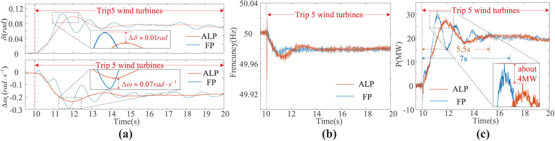
Figure 11: FP and ALP response of ESVG with tripping wind turbines. (a) ESVG δ and ωv; (b) Wind farm frequency; (c) ESVG output active power
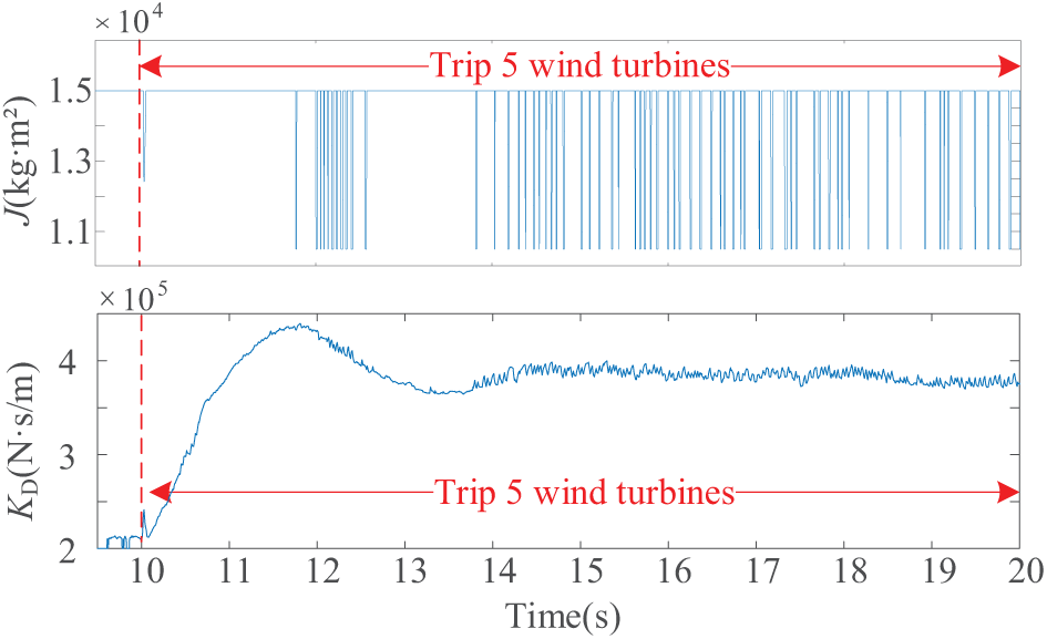
Figure 12: Trend of adjustment parameters during wind farm tripping
According to Fig. 11a, after the 10 s, five wind turbines were tripped. ESVG responds to the active-frequency support demand of the system, and its δ and |Δωv| gradually increase. At the time, ESVG outputs active power to the wind power system. Compared with the response process using FP, the response speed decreases slightly after using ALP (with a time lag of about 0.5 s for the maximum overshoot), but the overshoot of δ and |Δωv| decreased by 0.013 rad and 0.06 rad/s, respectively. In addition, if FP is used, the adjustment time of δ and |Δωv| is more than 10 s, and there is more obvious oscillation. On the contrary, after using ALP, the adjustment time of δ and |Δωv| were shortened to about 5 s.
From Fig. 11b,c, it can be seen that the use of FP and ALP has little effect on the frequency support ability of ESVG under the condition of wind turbine generator tripping within the time scale of primary frequency regulation (not more than 15 s). However, the output active power of ESVG using FP presents four oscillations and gradually stabilizes in 7 s. On the contrary, after using ALP, the number of oscillations was significantly reduced to 1, 4 MW reduced the output active power overshoot, the adjustment time was shortened from 7 s to 5.5 s, and the active response transition process became stable.
Combined with Figs. 11a and 12, it can be seen that with the increase of Δωv and the continuous change of dωv/dt, KD and J are adaptively adjusted, which effectively alleviates the fluctuation of ESVG’s δ and Δωv.
Under the wind turbine tripping scenario, Ug and its FFT analysis are shown in Figs. 12 and 13 after using the proposed ALP control strategy.
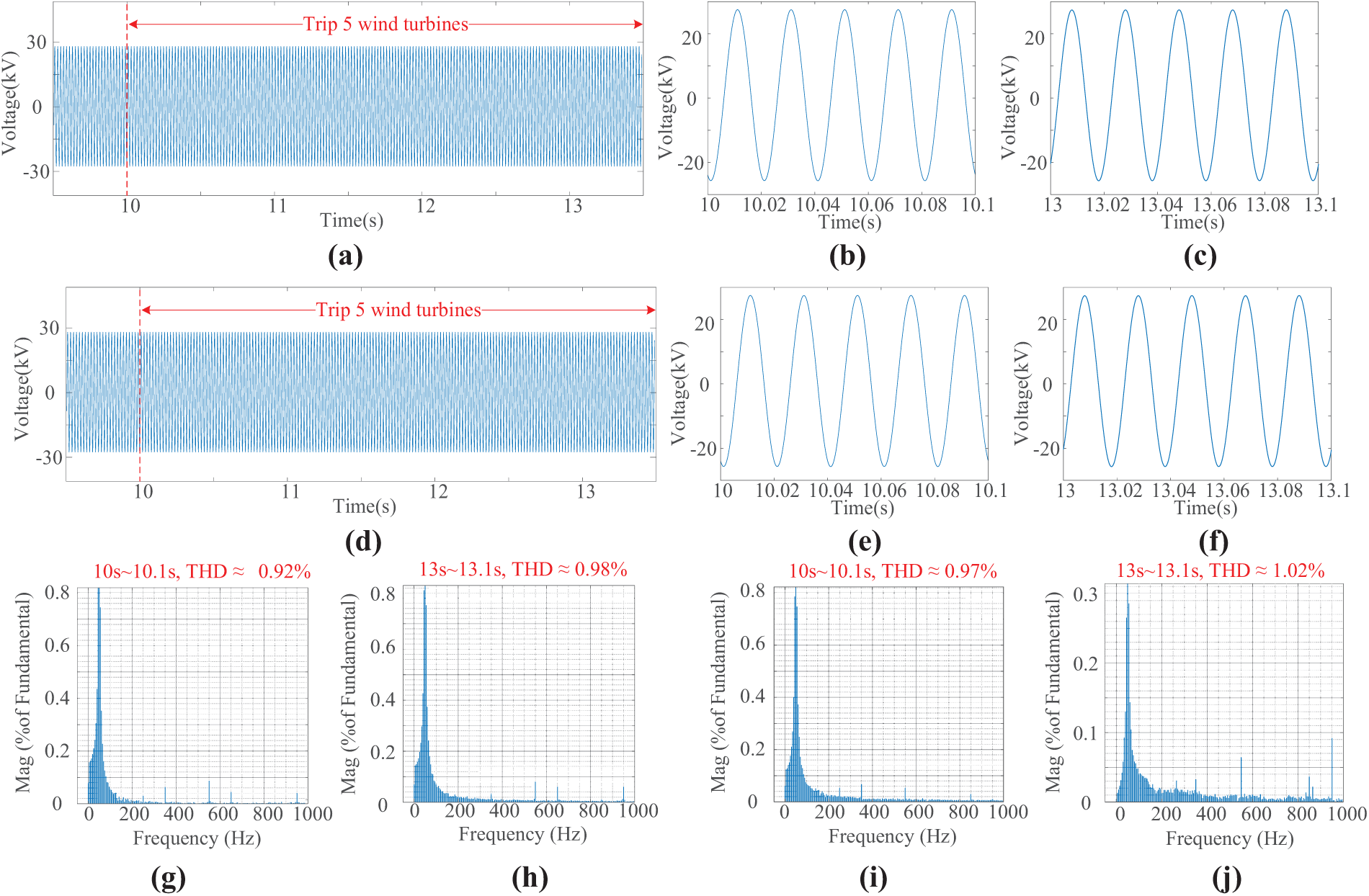
Figure 13: Ug and its FFT analysis with tripping five wind turbines. (a) Ug with ALP control; (b) Partially enlarged view of Ug with ALP control at 10 s; (c) Partially enlarged view of Ug with ALP control at 13 s; (d) Ug with FP control strategy; (e) Partially enlarged view of Ug with FP control strategy at 10 s; (f) Partially enlarged view of Ug with FP control strategy at 13 s; (g) THD with ALP control strategy at 10 s; (h) THD with ALP control strategy at 10 s; (i) THD with FP control strategy at 10 s; (j) THD with FP control strategy at 13 s
Fig. 13a–j shows the THD of ESVG’s Ug with FP and ALP at 10 s and 13 s under the scenario of wind turbines tripping. In 10 s, the THD of Ug with ALP control strategy is 0.92%, and that of FP control is 0.97%. The ALP control strategy reduces THD by 0.05% compared to the FP control strategy. In 13 s, the THD of Ug with ALP control strategy is 0.98%, and that of FP control strategy is 1.02%, which is 0.04% worse than that of ALP control strategy. It can be seen that under the wind turbine tripping scenario, the ALP control strategy can improve the THD of ESVG’s grid connected voltage to a certain extent, but to a small extent.
Fig. 14a–j shows the THD of ESVG’s Ig with FP and ALP control strategies at 10 and 13 s, respectively. In 10 s, the THD of the ALP control strategy is 6.11%, and that of the FP control strategy is 10.14%. The ALP control strategy reduced Ig THD by 4.03% compared to the FP control strategy. In the 13 s, the THD of the ALP control strategy is 6.58%, and that of the FP control strategy is 7.72%. Compared with the ALP control strategy, the FP control strategy worsens THD by 1.14%. Combined with the above analysis, the proposed ALP control strategy achieves the lowest THD and improves the power quality of ESVG’s Ig under the scenario of wind turbines tripping.
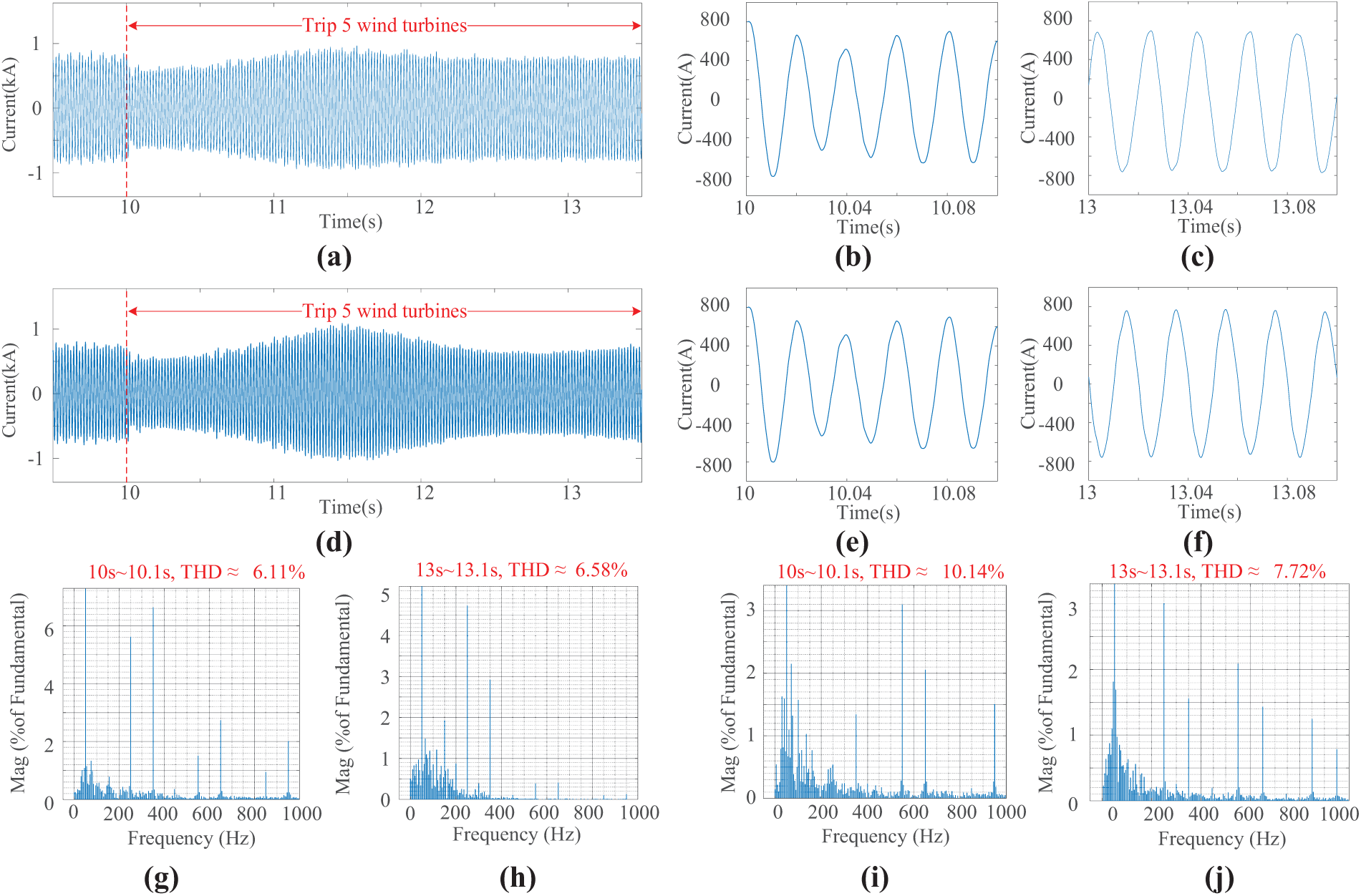
Figure 14: Ig and its FFT analysis with tripping five wind turbines. (a) Ig with ALP control strategy; (b) Partially enlarged view of Ig with ALP control strategy at 10 s; (c) Partially enlarged view of Ig with ALP control strategy at 13 s; (d) Ig with FP control strategy; (e) Partially enlarged view of Ig with FP control strategy at 10 s; (f) Partially enlarged view of Ig with FP control strategy at 13 s; (g) THD with ALP control strategy at 10 s; (h) THD with ALP control strategy at 10 s; (i) THD with FP control strategy at 10 s; (j) THD with FP control strategy at 13 s
To further verify the effectiveness of the proposed ALP control strategy, a 25 MW resistive load has been removed from the 220 KV side of the wind power system at 10 s. Figs. 15 and 16 show the trend of ESVG output active power changes and the response of key control variables.
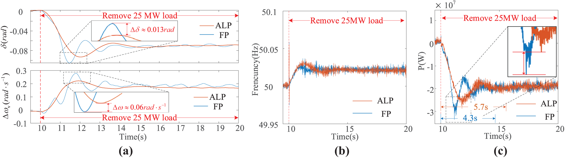
Figure 15: FP and ALP response of ESVG with removing 25 MW load. (a) ESVG δ and Δωv; (b) Wind farm frequency; (c) ESVG output active power
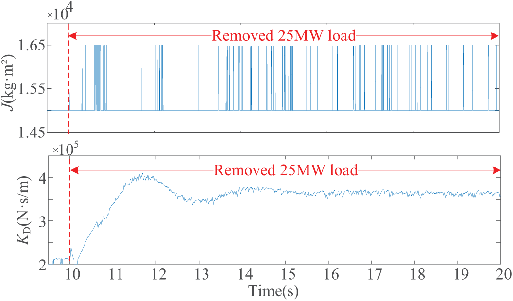
Figure 16: Variation trend of adjustment parameters during load removing
From Fig. 15a, it can be seen that ESVG responds to the active power-frequency support requirements of the system after 10 s. Similar to the wind turbine tripping, the variation of ESVG’s δ and ωv gradually increases, and the excess active power in the wind power system is absorbed. Compared to the response process using FP, the response speed slightly slows down after using ALP (with a time lag of about 0.5 s when the maximum overshoot occurs), but the overshoot of δ and Δωv are reduced by 0.013 rad and 0.07 rad·s−1, respectively. In addition, if FP is used, the adjustment time of ESVG’s δ and Δωv is about 8 s, and there are static errors of about 0.01 rad and 0.06 rad/s. On the contrary, after using ALP, the stabilization time is shortened to 5 s.
From Fig. 15b,c, it can be seen that the frequency support effect of ESVG with FP and ALP is the same for the load removed. However, the active power output of ESVG using FP presents three oscillation peaks and gradually stabilizes in 5 s. If ALP is used, the number of active power oscillations is significantly reduced. 6 MW reduces the absorbed active power overshoot, and the adjustment time is shortened from 5.7 s to 4.3 s. The transition process of active response is relatively smooth. Combining Figs. 15a with 16, it can be seen that with the increase of Δωv and the continuous change of dωv/dt, the adaptive adjustment of KD and J can effectively alleviate the fluctuation degree of the ESVG’s δ and Δωv.
Under the load fluctuation scenario, grid connected voltage, the compensation current of ESVG using the proposed ALP control strategy, and their respective FFT analysis are shown in Figs. 17 and 18.

Figure 17: Ug and its FFT analysis with removing 25 MW resistive load. (a) Ug with ALP control strategy; (b) Partially enlarged view of Ug with ALP control strategy at 10 s; (c) Partially enlarged view of Ug with ALP control strategy at 13 s; (d) Ug with FP control strategy; (e) Partially enlarged view of Ug with FP control strategy at 10 s; (f) Partially enlarged view of Ug with FP control strategy at 13 s; (g) THD with ALP control strategy at 10 s; (h) THD with ALP control strategy at 10 s; (i) THD with FP control strategy at 10 s; (j) THD with FP control strategy at 13 s
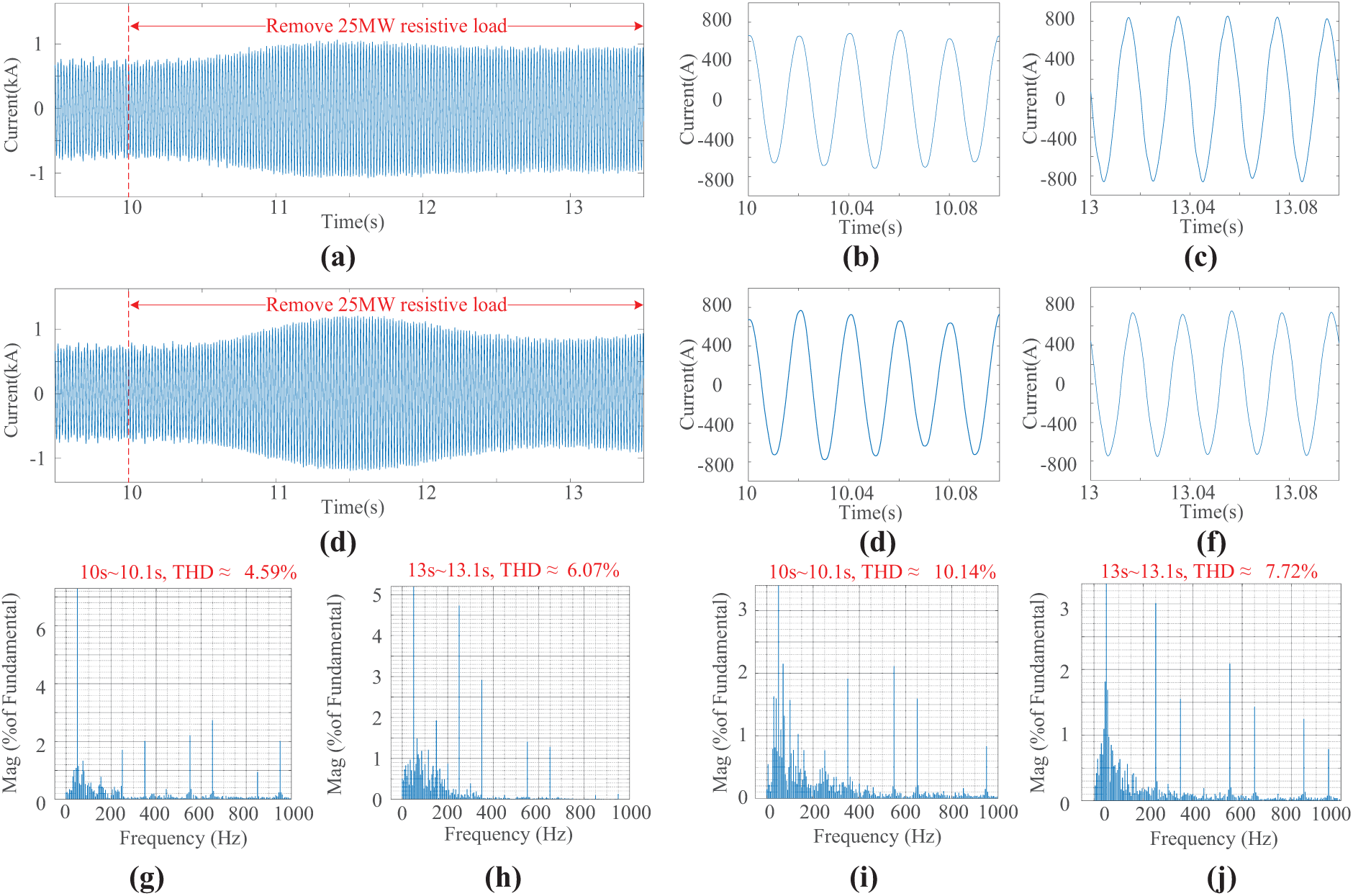
Figure 18: Ig and its FFT analysis with removing 25 MW resistive load. (a) Ig with ALP control strategy; (b) Partially enlarged view of Ig with ALP control strategy at 10 s; (c) Partially enlarged view of Ig with ALP control strategy at 13 s; (d) Ig with FP control strategy; (e) Partially enlarged view of Ig with FP control strategy at 10 s; (f) Partially enlarged view of Ig with FP control strategy at 13 s; (g) THD with ALP control strategy at 10 s; (h) THD with ALP control strategy at 10 s; (i) THD with FP control strategy at 10 s; (j) THD with FP control strategy at 13 s
Fig. 17a–j shows the THD of ESVG’s Ug with FP and ALP control strategies at 10 s and 13 s under the scenario of load fluctuation. In 10 s, the THD of Ug with ALP control strategy is 1.17%, and that of FP control strategy is 0.97%. ALP control strategy reduces THD by 1.38% compared to FP control strategy. In 13 s, the THD of Ug with ALP control strategy is 0.84%, and that of FP control strategy is 1.02%, which is 0.18% worse than that of ALP control strategy. It can be seen that under the load fluctuation scenario, the ALP control strategy can improve the THD of the ESVG grid-connected voltage to a certain extent, but only to a small extent.
Fig. 18a–j shows ESVG’s Ig and its THD with FP and ALP control strategies at 10 and 13 s, respectively. In 10 s, the THD of the ALP strategy is 4.59%, and that of the FP control strategy is 10.14%. ALP control strategy reduces THD by 5.55% compared to FP control strategy. In the 13 s, the THD of the ALP control strategy is 6.07%, and that of the FP control strategy is 7.72%. Compared with the ALP control strategy, the FP control strategy worsens THD by 1.65%. The above results show that the proposed ALP control strategy achieves the lowest THD and improves the power quality of ESVG under a load fluctuation scenario.
In the face of frequency change in wind power systems, the rapid support ability and potential operation risk of ESVG are studied, and the solution is provided. The conclusions are as follows:
(1) To ensure the control system’s stability margin, the ESVG active power control loop’s ESVG active power adjusting speed decreases as the virtual rotation inertia increases. The increase in the virtual damping coefficient will expand the range of virtual angular velocity, thus reducing ESVG’s fast frequency support ability.
(2) In the process of ESVG outputting active power to the wind power system, the equivalent virtual inertia is positively correlated with the capacitance of the supercapacitor installed on the DC side. As the capacitance of the supercapacitor increases, the frequency support ability of ESVG increases in the wind power system.
(3) To enhance the operational stability of ESVG in supporting the frequency of wind farms, the proposed ALP control strategy, considering the equivalent inertia of the DC-side supercapacitor, can effectively suppress the fluctuation of ESVG active output and virtual angular velocity without changing the control structure. This is beneficial for frequency support for wind power systems. Moreover, ALP also ensures the excellent grid-connected power quality of ESVG.
Acknowledgement: The authors express their gratitude to the editor and anonymous reviewers for their reviews and valuable comments. And all individuals included in this research have consented to the acknowledgment.
Funding Statement: This research was funded by the Science and Technology Project of State Grid Corporation, grant number 5500-202329500A-3-2-ZN, funding data 2023.10–2025.12.
Author Contributions: The authors confirm contribution to the paper as follows: study conception and design: Yong Sun, Jiayang Zhang; data collection: Yifu Zhang, Song Gao; analysis and interpretation of results: Yong Sun, Haifeng Zhang, Xiaozhe Song; draft manuscript preparation: Xiaozhe Song, Jiayang Zhang, Song Gao. All authors reviewed the results and approved the final version of the manuscript.
Availability of Data and Materials: The authors confirm that the data used in this study are available on request. Data supporting this study are included in the article.
Ethics Approval: Not applicable.
Conflicts of Interest: The authors declare no conflicts of interest to report regarding the present study.
Abbreviations
| ESVG | Energy Storage Type Static Var Generator |
| SVG | Static Var Generator |
| ALP | Adaptive adjustment of active loop parameters |
| FP | Fixed Parameter |
| VSG | Virtual Synchronous Generator |
References
1. Yang B, Li H, Xu S, Liu H, Lu S. Systematic methods to eliminate the transient circulating powers in the multi-VSGs system. IEEE Trans Smart Grid. 2024;15(1):179–90. doi:10.1109/TSG.2023.3288045. [Google Scholar] [CrossRef]
2. Li Y, Yuan X, Li J, Xiao H, Xu Z, Du Z. Novel Grid-forming control of permanent magnet synchronous generator-based wind turbine for integrating weak AC grid without sacrificing maximum power point tracking. IET Gener Transm Distrib. 2021;15(10):1613–25. doi:10.1049/gtd2.12121. [Google Scholar] [CrossRef]
3. Meng Q, Ren Y, Liu H. Frequency stability analysis of grid-forming PMSG based on virtual synchronous control. IEEE Access. 2024;12(15):84134–48. doi:10.1109/ACCESS.2024.3414424. [Google Scholar] [CrossRef]
4. Roscoe A, Knueppel T, Da Silva R, Brogan P, Gutierrez I, Elliott D, et al. Response of a grid forming wind farm to system events, and the impact of external and internal damping. IET Renew Power Gener. 2020;14(19):3908–17. doi:10.1049/iet-rpg.2020.0638. [Google Scholar] [CrossRef]
5. Nguyen TT, Vu T, Paudyal S, Blaabjerg F, Vu TL, Vu TL. Grid-forming inverter-based wind turbine generators: comprehensive review, comparative analysis, and recommendations. arXiv:2203.02105. 2022. [Google Scholar]
6. Akram U, Mithulananthan N, Raza MQ, Shah R, Milano F. RoCoF restrictive planning framework and wind speed forecast informed operation strategy of energy storage system. IEEE Trans Power Syst. 2021;36(1):224–34. doi:10.1109/TPWRS.2020.3001997. [Google Scholar] [CrossRef]
7. Meng G, Chang Q, Sun Y, Rao Y, Zhang F, Wu Y, et al. Energy storage auxiliary frequency modulation control strategy considering ACE and SOC of energy storage. IEEE Access. 2021;9:26271–7. doi:10.1109/ACCESS.2021.3058146. [Google Scholar] [CrossRef]
8. Panda M, Bhaskar DV, Maity T. A novel power management strategy for hybrid AC/DC microgrid. In: 2019 IEEE 16th India Council International Conference (INDICON); 2019 Dec 13–15; Rajkot, India. [Google Scholar]
9. Zhu JB, Shi MQ, Zhang L, Ge LJ, Yu LJ, Deng ZS, et al. Coordinated inertia support strategy of offshore wind power flexible direct transmission system based on super capacitor. Power Syst Technol. 2022;46(8):2938–52. (In Chinese). doi:10.13335/j.1000-3673.pst.2022.0283. [Google Scholar] [CrossRef]
10. Liu QY, Huang WH, Guo Z, Zhu HX, Liu F. Reactive power distribution strategy of multi-parallel grid-connected converter based on adaptive virtual impedance. Autom Electr Power Syst. 2024;48(15):122–30. (In Chinese). doi:10.7500/AEPS20231005002. [Google Scholar] [CrossRef]
11. Ghimire S, Kkuni KV, Jakobsen SC, Knueppel T, Jensen KH, Guest E, et al. Grid-forming control methods for weakly connected offshore WPPs. IET Conf Proc. 2023;2023(20):246–53. doi:10.1049/icp.2023.2744. [Google Scholar] [CrossRef]
12. Henderson C, Egea-Alvarez A, Xu L. Analysis of optimal grid-forming converter penetration in AC connected offshore wind farms. Int J Electr Power Energy Syst. 2024;157(19):109851. doi:10.1016/j.ijepes.2024.109851. [Google Scholar] [CrossRef]
13. Yang TX, Huang YH, He ZY, Wang D, Tang JR, Xie CJ. Optimal configuration of fixed-capacity location of grid-connected energy storage power station based on multi-time scale adjustment. Autom Electr Power Syst. 2024;48(23):54–64. (In Chinese). doi:10.7500/AEPS20240320002. [Google Scholar] [CrossRef]
14. Zhang JW, Zhang S, Shi QX, Zhang Y, Huang L, Cai X. Energy storage static var generator and its self-synchronous voltage source control. High Volt Eng. 2022;49(1):67–71. (In Chinese). doi:10.13336/j.1003-6520.hve.20220576. [Google Scholar] [CrossRef]
15. Sun D, Liu H, Gao S, Wu L, Song P, Wang X. Comparison of different virtual inertia control methods for inverter-based generators. J Mod Power Syst Clean Energy. 2020;8(4):768–77. doi:10.35833/MPCE.2019.000330. [Google Scholar] [CrossRef]
16. Chen S, Han H, Wu Z, Luo Z, Liu Z, Liu Y, et al. Distributed frequency interactive damping control for multiple VSGs in islanded microgrids. IEEE Trans Circuits Syst I. 2024;71(8):3867–79. doi:10.1109/TCSI.2024.3399790. [Google Scholar] [CrossRef]
17. Xue T, Zhang J, Bu S. Inter-area oscillation analysis of power system integrated with virtual synchronous generators. IEEE Trans Power Deliv. 2024;39(3):1761–73. doi:10.1109/TPWRD.2024.3376523. [Google Scholar] [CrossRef]
18. Mao X, Su H, Li J. Research on grid-connected control strategy of distributed generator based on improved linear active disturbance rejection control. Energy Eng. 2024;121(12):3929–51. doi:10.32604/ee.2024.057106. [Google Scholar] [CrossRef]
19. Saadatmand S, Shamsi P, Ferdowsi M. Power and frequency regulation of synchronverters using a model free neural network-based predictive controller. IEEE Trans Ind Electron. 2021;68(5):3662–71. doi:10.1109/TIE.2020.2984419. [Google Scholar] [CrossRef]
20. Tan L, Yi M, Cai L, Zhang H, Hou P, Han J. Adaptive control strategies for improving frequency response parameters in VSG. IEEE Access. 2024;12(24):160359–68. doi:10.1109/ACCESS.2024.3488895. [Google Scholar] [CrossRef]
21. Li G, Ma F, Wang Y, Weng M, Chen Z, Li X. Design and operation analysis of virtual synchronous compensator. IEEE J Emerg Sel Top Power Electron. 2020;8(4):3835–45. doi:10.1109/JESTPE.2019.2943723. [Google Scholar] [CrossRef]
22. Wu H, Wang X. Control of grid-forming VSCs: a perspective of adaptive fast/slow internal voltage source. IEEE Trans Power Electron. 2023;38(8):10151–69. doi:10.1109/TPEL.2023.3268374. [Google Scholar] [CrossRef]
23. Shuai Z, Shen C, Liu X, Li Z, Shen ZJ. Transient angle stability of virtual synchronous generators using Lyapunov’s direct method. IEEE Trans Smart Grid. 2019;10(4):4648–61. doi:10.1109/TSG.2018.2866122. [Google Scholar] [CrossRef]
24. Chen S, Sun Y, Hou X, Han H, Fu S, Su M. Quantitative parameters design of VSG oriented to transient synchronization stability. IEEE Trans Power Syst. 2023;38(5):4978–81. doi:10.1109/TPWRS.2023.3293016. [Google Scholar] [CrossRef]
25. He X, Desai MA, Huang L, Dörfler F. Cross-forming control and fault current limiting for grid-forming inverters. IEEE Trans Power Electron. 2025;40(3):3980–4007. doi:10.1109/TPEL.2024.3500885. [Google Scholar] [CrossRef]
26. Pan D, Wang X, Liu F, Shi R. Transient stability of voltage-source converters with grid-forming control: a design-oriented study. IEEE J Emerg Sel Top Power Electron. 2019;8(2):1019–33. doi:10.1109/JESTPE.2019.2946310. [Google Scholar] [CrossRef]
Cite This Article
 Copyright © 2025 The Author(s). Published by Tech Science Press.
This work is licensed under a Creative Commons Attribution 4.0 International License , which permits unrestricted use, distribution, and reproduction in any medium, provided the original work is properly cited.
 Downloads
 Citation Tools