
 Submit a Paper
 Propose a Special lssue
 Open Access
ARTICLE

In-Situ Study on the Effect of Gas Stove Structure on Flame Combustion Characteristics Based on Spectral Diagnosis
1 State Key Laboratory of High-Efficiency Utilization of Coal and Green Chemical Engineering, School of Chemistry and Chemical Engineering, Ningxia University, Yinchuan, 750021, China
2 Co-Innovation Center of Efficient Processing and Utilization of Forest Resources, School of Materials Science and Engineering, Nanjing Forestry University, Nanjing, 210037, China
3Marssenger Kitchenware Co., Ltd., Jiaxing, 314400, China
4 Chemical and Environmental Engineering, School of Engineering, RMIT University, Melbourne, VIC 3000, Australia
5 Department of Chemical Engineering, Indian Institute of Technology Jodhpur, Jodhpur, 342030, Rajasthan, India
6 Institute of Clean Coal Technology, East China University of Science and Technology, Shanghai, 200237, China
* Corresponding Authors: Juntao Wei. Email: ; Xudong Song. Email:
Energy Engineering 2025, 122(7), 2637-2652. https://doi.org/10.32604/ee.2025.065407
Received 12 March 2025; Accepted 30 May 2025; Issue published 27 June 2025
 View Full Text
 Download PDF
Abstract
This study systematically investigated the effects of different gas stove structures on flame combustion characteristics using spectral diagnostic techniques, aiming to provide optimized design guidelines for clean energy applications. To explore the combustion behaviors of various gas stove structures, UV cameras, high-speed cameras, and K-type thermocouples were employed to measure parameters such as flame OH radicals (OH*), flame morphology, pulsation frequency, flame temperature, and heat flux. The results demonstrate that flame stability was achieved at an inner/outer cover flow rate ratio of 0.5/4.0 L/min, beyond which further flow rate increases led to reduced combustion efficiency. Compared to covered stoves, top-uncovered stove exhibited 5.5% and 12.4% higher temperatures at the inner and outer covers, respectively, along with a 35% increase in heat flux. Comprehensive analysis revealed an approximately 20% enhancement in overall flame intensity. The experimental results show that top-uncovered gas stoves exhibit higher flame intensity, greater combustion efficiency, and overall higher stove efficiency. In contrast, covered gas stoves feature a more controllable and stable flame with a gentler temperature rise. This study underscores the importance of optimizing gas stove designs to enhance combustion efficiency and reduce emissions, contributing to the transition from fossil fuels to renewable energy sources and promoting sustainable development.Keywords
Since China is dealing with severe environmental pollution issues [1,2], stricter regulations are being placed on the emission rates of harmful pollutants resulting from energy consumption [3–5]. Natural gas is expected to play an increasingly critical role as a clean energy source in the future energy structure [6,7]. The main component of natural gas is methane, which is widely utilized across various sectors and has become one of China’s primary energy sources [8]. The widespread use of natural gas will be crucial for transitioning from fossil fuels to renewable energy sources, thereby addressing environmental issues and promoting sustainable development [9,10].
Since gas stoves are the primary equipment used to consume natural gas, their energy efficiency is essential for living a green and environmentally friendly life. Many Chinese households use natural gas [11], and most have gas stoves in their homes. Flame stability is one of the key performance indicators for gas stoves [12]. It is affected by various factors, including burner layouts, fuel types, and the magnitude of the equivalency ratio [13]. Furthermore, several elements influence the burner’s efficiency, such as the temperature at which the gas ignites [14], the rationality of the stove’s design [15], the complete combustion of the gas [16], the fuel supply, and the radiant heat loss from the flame to the outside [17]. All of these factors can lead to energy loss from the gas stove, potentially lowering its thermal efficiency [18]. One essential component of a gas stove, the stove surface, directly impacts how well the stove burns [19].
In recent years, various studies have focused on the effects of different structures of gas stoves on flame stability [20]. Through experimental research, Fang et al. [21] discovered that various stove head structure designs could have a substantial impact on flame stability and that some structural designs can increase it. Zhang et al. [22] found that increasing gas pressure significantly reduces thermal efficiency and has varying effects on CO and NOx emissions. They emphasize that optimizing combustion and heat transfer structure design, rather than merely increasing pressure, can better balance heat input rate and thermal efficiency. Wu et al. [23] proposed a waste-heat-recovery gas stove incorporating an enclosed combustion chamber and premixed combustion technology, which significantly enhanced thermal efficiency and addressed energy efficiency issues associated with open combustion. This study provides novel insights for energy-saving optimization and integrated design of gas stoves. In conclusion, these studies underscore the significant impact that gas stove design has on flame stability and combustion efficiency, highlighting the necessity for ongoing research to optimize these appliances for better performance and safety.
The innovation and improvement of detection techniques have significantly advanced the diagnosis and detection of the flame combustion process [24,25]. As a result, more researchers started to focus on the widespread industrial use of flame diagnostic technology [26–29], paving the way for future research on the flame combustion state and providing a strong foundation [30]. Spectral signals can be used to depict the composition and morphology of the change rule as well as the internal structure of the combustion flame [31]. Hu et al. [32] used OH* and CH* to characterize the flame structure, and Li et al. [33] studied methane/air native flame turbulence collision, flame dynamics, thermal imaging, and other topics using planar laser-induced fluorescence (OH-PLIF), high-speed cameras, fast Fourier transform (FFT), and other processing techniques. the advancements in detection techniques not only enhance our understanding of flame combustion processes but also enable more precise diagnostics and monitoring in industrial applications.
Thus, by thoroughly examining how various stove head configurations affect flame stability, it will be possible to provide a more rational and scientific foundation for the design of gas stoves, thereby increasing combustion efficiency and safety. Based on the experimental data of gas stove combustion under different flow rates, this study systematically investigates the performance of gas stoves with varying structures at various flow rates. Through the processing and analysis of the experimental data, the laws and characteristics of the changes in these performance parameters with the flow rate are explored in depth, providing an essential reference for further understanding the combustion characteristics of gas stoves.
The flame spectroscopy diagnostic experimental platform consists of a flame detection system and a flame-producing apparatus. Fig. 1 displays the experimental device’s schematic diagram. A mass flow meter (CS200A, Beijing Seven Star Flow Co., Ltd., Beijing, China) was used in the flame generation system to regulate the methane flow. A high-speed camera system (PCO dimax S1, Kelheim, Germany) recorded the flame morphology; a type K thermocouple (JT2020, Multi-function tester, Beijing, China) recorded the temperature; a heat flux sensor recorded the heat flux; and a high-resolution ultraviolet(UV)-Vis camera system (EX-4710B, Wuzu Optical Co., Taiwan) detected the excited radicals in the flame. The gas stoves used in the experiment were all coaxial dual-channel non-premixed atmospheric burners (with both inner and outer ring channels). During the experiment, the structure of the outer ring cover remained consistent, featuring a closed top and uniformly distributed small holes along the sides. Two different structural designs of the covers were designated as A and B, each with distinct characteristics. Specifically, Stove A is relatively smaller, with a closed top for the inner ring cover and openings on the sides that taper inward at the top. In contrast, Stove B is slightly larger, with a top that has numerous small, dense holes, and also features openings along the sides. The actual picture of the stove is shown in Fig. 2 ((a) shows the structure of stove A, (b) shows the structure of stove B, and (c) shows the structure of the outer fire cover of the stove).
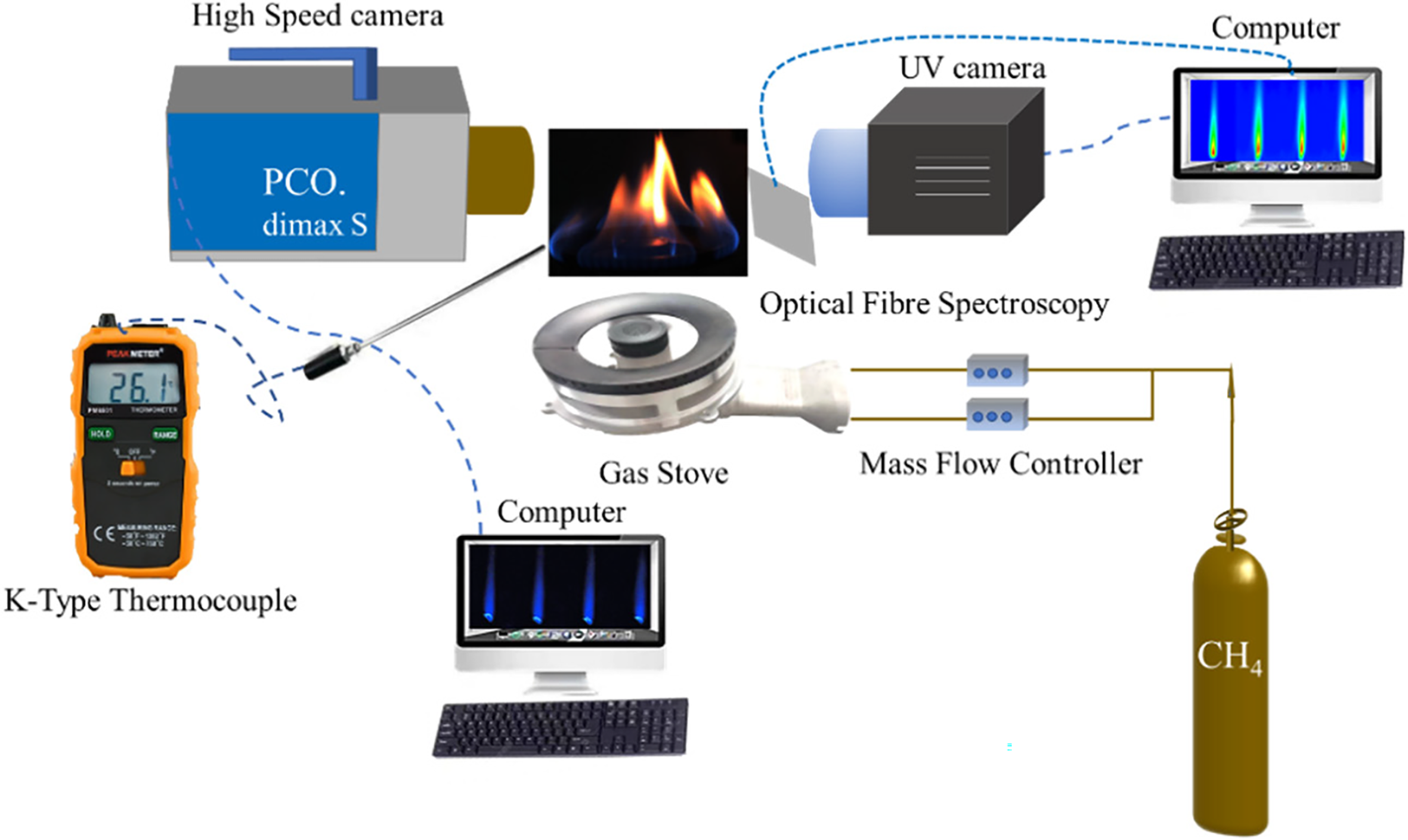
Figure 1: Schematic diagram of the experimental setup

Figure 2: Schematic diagram of the structure of different stoves: (a) structure of inner cover A, (b) structure of inner cover B, and (c) structure of the outer cover of the stove
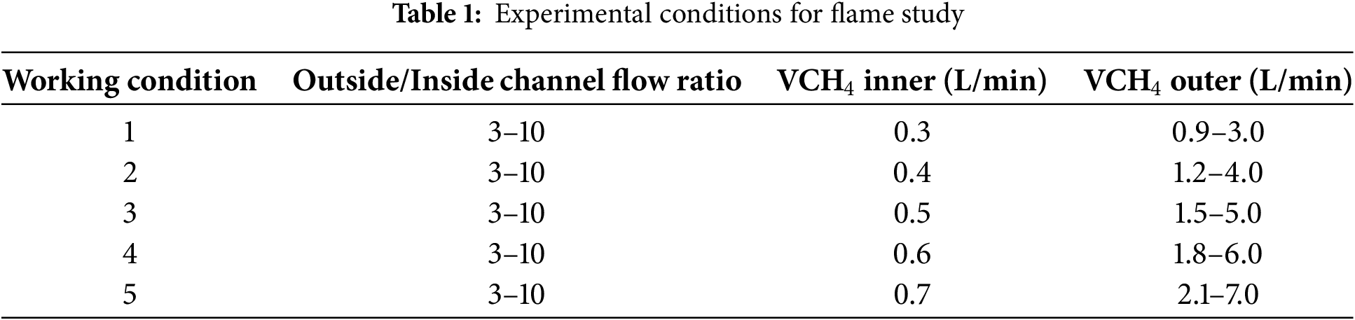
In this experiment, CH4 (purity > 99.9%) was used as the fuel, and the surrounding air was used as the oxidant. Different CH4 flow rate were delivered into the gas stove’s inner and outer channel. A fixed methane flow rate in the inner cover channel (0.3–0.7 L/min with 0.1 L/min intervals) was used to investigate the effects of varying flow rate on flame characteristics. The flow rate in the outer cover channel was set to be a multiple of the inner channel’s methane flow rate, and the experimental conditions under various stove configurations were maintained. The specific working conditions are summarized in Table 1.
A high-speed camera captured the flame transient patterns of methane fuel combustion with air under various stove configurations. The graphs show a progressive rise in methane flow in the inner cover from top to bottom and a gradual rise in flow in the outer cover from left to right.
The flame of gas stove A appears blue when the outer cover is functioning properly with methane, indicating that the flame burns more completely and exhibits only the blue color associated with the free radical emission spectra, as illustrated in Figs. 3 and 4 for both stove configurations. The yellow flame emerges significantly earlier downstream of stove B compared to stove A when the inner cover flow increases. As the inner cover flow increases, the flame height rises, causing the yellow flame to appear somewhat sooner downstream of stove B. This observation suggests that the airflow rate to the coil is insufficient for complete combustion of methane, resulting in the appearance of a yellow flame at the tip. In contrast, the trend of flame morphology temains consistent as the outer cover flow rate increases for any given inner cover flow rate. It is evident from the comparison of the flame morphology in both images at the same flow rate that stove B exhibits a substantially higher flame height than stove A. The uncovered top of stove B facilitates a smoother release of fuel at the same flow rate, allowing for a more thorough mixing of fuel with oxygen during combustion and thereby the combustion reaction. Observations of the flame combustion in the figure reveal that when the ratio ofinner-to-outer cover methane flow rate is lower, the shape of the inner cover flame is more pronounced, the flame is more stable, and the outer cover flame appears entirely blue, indicating more complete combustion. This may be attributed to the increased burning of methane in the outer cover, which concentrates more flame energy when there is a strong outer cover methane flow. As the outer cover flow increases, the flame becomes predominantly concentrated in the outer cover, effectively rendering the shape of the inner cover flame nearly unnoticeable.

Figure 3: Variation of flame morphology under different conditions in stove A (0.7-0.0-0 indicates inner cover flow rate/outer cover flow rate/flow ratio)

Figure 4: Variation of flame morphology under different conditions in stove B
3.2 Flame Pulsation Frequency Changes
To enable a more precise comparison of the pulsation frequency under the two stove structures, the dynamic characteristics of the flame, including pulsation frequency, rhythm, and stability, were analyzed using the quantified flame pulsation frequency in Fig. 5. The time taken for the flame to complete one pulsation process is defined as the cycle time. Changes in fuel flow rate are represented on the horizontal axis, while the flame’s pulsating frequency is depicted on the vertical axis. As the outer cover flow rate gradually increases, the flame vibration frequency exhibits a trend of first increasing, then decreasing, and subsequently increasing again, as illustrated in the pulsation frequency results. This may be attributed to a higher gas flow rate enhancing the coiling and sucking effects of flame combustion, which facilitates more complete fuel combustion and subsequently increases the frequency of the flame’s pulsation. When comparing stove A to stove B, it is evident that stove A’s pulsation frequency is lower. This phenomenon can be explained by the differing stove structures that influence the combustion characteristics of the flame. Specifically, the flame on an uncovered stove burns more intensely and smoothly, resulting in a higher pulsation frequency. In contrast, the flame on a covered stove demonstrates a lower pulsation frequency. Furthermore, higher gas flow rates lead to more frequent flame pulsations. This suggests that utilizing an open-top stove enhances the efficiency of flame combustion, thereby improving the overall efficiency of the gas stove.

Figure 5: Frequency diagram of flame vibration for the same flow rate for stoves of different configurations
The resulting vibration frequency diagram is displayed in Fig. 5. Take the time for the flame to complete one pulsation process as the cycle time. Fuel flow rate changes is represented by the horizontal coordinate and the flame’s pulsating frequency by the vertical coordinate.
The distribution of OH radicals in a flame is a crucial indicator of both the activity and stability of the flame reaction, as well as its burning and radiation intensity. In this context, studying the two-dimensional distribution of OH radicals allows for a more in-depth investigation of the combustion process within the flame, encompassing the mixing of fuel and oxygen, the degree of combustion reaction, and the temperature distribution of the flame. The flame OH* for stoves with different structures is illustrated in Figs. 6 and 7.

Figure 6: Variation of two-dimensional distribution of flame OH* for different conditions in stove A

Figure 7: Variation of two-dimensional distribution of flame OH* for different conditions in stove B
According to the findings presented in Figs. 6 and 7, the absence of outer cover flow leads to a slight increase in radiation intensity and flame height due to the increase in inner cover flow, though this effect is minimal. As the outer cover flow rate increases, the flame height decreases, and the outer cover flames converge towards the inner cover flame, resulting in a more compact flame structure, provided the inner cover flow remains constant. At higher outer cover flow rates, the outer cover flame dominates the combustion process, pushing the inner cover flame upward and causing the overall flame to rise, with radiation intensity concentrated primarily in the flame’s middle section. When the outer cover flow rate increases while the inner cover flow is held constant, the outer cover flow significantly affects both flame morphology and energy distribution. At lower outer cover flow rates, the flames converge into a more concentrated structure with relatively small flame height. However, as the outer cover flow rate exceeds a certain threshold, the outer cover flame intensifies and expands, ultimately dominating the combustion process and driving the inner cover flame higher, resulting in a larger flame structure. In this case, both flame height and radiation intensity increase, with peak radiation intensity concentrated in the middle of the flame. This leads to a more uniform energy distribution and enhanced radiation.
A covered stove design enhances the efficiency of light radiation from the flame, resulting in a more focused and potent energy output. This structure increases the flame’s radiation intensity by reducing heat and light radiation dissipation and limiting airflow around it. At the same flow rate, stove A demonstrates a more concentrated OH* distribution, with a smaller radiation area and higher intensity. In contrast, the uncovered stove is more influenced by the surrounding environment, leading to a more dispersed radiation intensity from the flame.
Based on the comparison of Figs. 6 and 7, it is evident that the OH* radiation intensity of stove B is greater than that of stove A. To further investigate the reasons behind the increased OH* radiation intensity of stove B, both radial and axial analyses were conducted. The radial analysis provides insights into the distribution of OH* radiation intensity within the flame’s cross-section, revealing the internal structure and combustion characteristics of the flame. Conversely, the axial analysis illustrates the variation of OH* radiation intensity along the direction of flame propagation, allowing for the observation of trends in OH* radiation intensity at different heights or distances, as demonstrated in Figs. 8 and 9.

Figure 8: Radial dimensions of OH* along the axial flame for different fuel flow rate
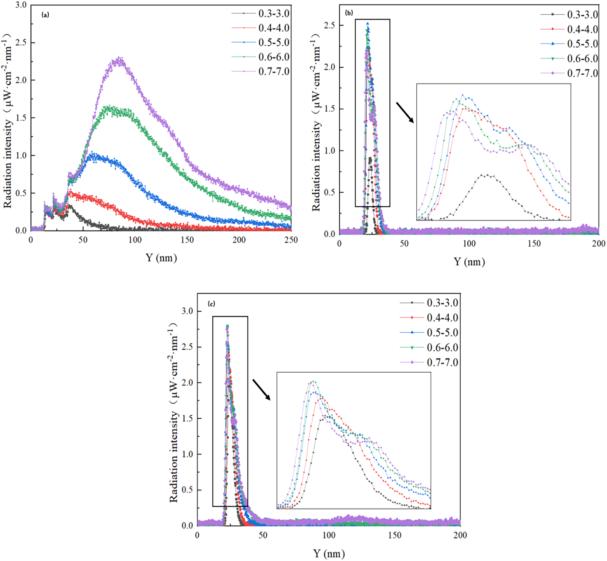
Figure 9: Radial distribution of OH* along the flame axis with different fuel velocity (Y: Distance from fire cover end face): (a) axial distribution of midpoints (b) axial distribution of left lateral points (c) axial distribution of right-hand points
Upon investigating the radial distribution of OH* at varying flow rates in Fig. 8, it is evident that the burner cross-section exhibits six symmetrical peak structures, with the most significant peak located at the edge of the outer cover at an axial height of 25 mm. This suggests that the flame reaction is strongest near the edge of the fire cover, likely due to the interaction of the flame with the surrounding environment and airflow distribution. The OH* radiation intensity reaches its maximum at an inner cover flow rate of 0.6 L/min, which corresponds to a more stable and complete combustion process, facilitating the formation and accumulation of OH radicals. However, at a flow rate of 0.7 L/min, the radiation intensity decreases significantly, likely due to uneven fuel-air mixing, which prevents complete combustion and reduces OH production. Additionally, as the methane flow rate increases, the OH radiation intensity also increases, indicating that higher methane flow enhances combustion and the production of OH radicals.
3.4 Axial Distribution of OH* Radiation Intensity
Fig. 9 illustrates the axial distribution of OH* at various radial locations, corresponding to different inner and outer cover flow rate. The location exhibiting the highest radiation intensity of OH* can be identified as the reaction core of the flame. Based on the radial distribution of OH* radicals presented in Fig. 9, two points at the edge of the outer cover and one point at the central axis of the flame, where the radiation intensity is highest, were selected for analysis. In the graph, the horizontal coordinate represents the height of the flame, with the coordinate x set to 0 indicating the end face of the burner’s fire cover. The vertical coordinate denotes the magnitude of the peak flame intensity.
Based on the observation results of the flame OH* axial distribution at the three radial points in Fig. 9. The intensity of the flame OH free radical axial radiation exhibits a trend of gradual increase followed by gradual decrease along the direction of flame propagation. The change is more pronounced, with the maximum radiation intensity of OH* being greater at the left and right points than at the central axis. However, the variation at the flame’s center is more gradual. Further examination of the variations in the axial radiation intensity of the flame OH* at different points reveals that, as the height from the end face of the flame cover increases, the reaction rate at the left point occurs first, followed by that at the right point, and lastly at the center point of the flame. This suggests that chemical reactions are more likely to occur at the edges of the flame, which may be attributed to the increased mixing of fuel with oxygen in those regions. Furthermore, in correlation with the measurements of the flame morphology map, the intensity of the flame OH* radicals’ radiation increases with an increase in inner cover flow. This could be explained by the rise in the inner cover flow leading to an increase in the flame volume and an increase in the fuel-oxygen contact area. Therefore, the increase in inner cover flow significantly affects the morphology and combustion characteristics of the flame, which in turn influences the radiation intensity of the flame OH* radicals.
3.5 Flame Heat Flux Distribution
The heat flux of the flame is closely associated with its stability. When the inner cover flow rate is set at 0.3 L/min, the change in heat flux is minimal. However, at an inner cover flow rate of 0.7 L/min, the outer cover flow rate increases significantly, which impacts the measurement of heat flux. Therefore, the heat flux change graphs for the flame with inner cover flow rates of 0.4, 0.5, and 0.6 L/min have been selected to examine the trend of flame heat flux under varying ratios of inner and outer cover flow rates, as illustrated in Fig. 10.

Figure 10: Distribution of flame heat flux at different inner cover and corresponding outer cover flow rate of stove: (a) stove A (b) stove B
From Fig. 10, it is evident that the heat flux of the flame from the gas stove exhibits a gradual increase with the rise in the inner cover flow, provided that there is no outer cover flow. Furthermore, when the inner cover flow rate is held constant, the flame heat flux in stove B increases from 174 to 1030 W/m2 as the outer cover flow rate increases. When the outer cover flow rate is quadrupled, the flame heat flux rises from 206 to 1430 W/m2, and when it is increased eightfold, the heat flux escalates from 237 to 1697 W/m2. In contrast, stove A’s flame heat flux fluctuates between 154 and 1279 W/m2. The trend observed in the graph clearly indicates that flame heat flux increases linearly with the outer cover flow rate. This linear relationship suggests that regulating the outer cover flow can effectively control the heat flux of the gas stove. For the same inner cover flow rate and corresponding outer cover flow rate, stove B demonstrates a significantly higher heat flux density compared to stove A. This finding implies that the top uncovered stove produces a stronger flame and higher heat flux. In comparison to stove A, stove B experiences a more pronounced increase in flame heat flux. This phenomenon can be attributed to the design structure of stove B, which enhances the combustion reaction and air-gas mixing, thereby ensuring a sufficient oxygen supply. A more thorough combustion process leads to improved mixing efficiency.
3.6 Flame Temperature Variation Graph
Fig. 11 illustrates the variations in flame temperature as the inner cover flow increases, while the outer cover flow remains absent. Additionally, Fig. 11a,b compares and analyzes the temperature variation patterns of the inner and outer covers under the same working conditions. The research results show that when the flow rates of the inner and outer covers reach a ratio of 0.5/4.0 L/min, both temperatures reach their peak values, but the temperature of the outer cover remains consistently higher than that of the inner cover. Fig. 11b,c depicts the changes in flame temperature at the edge of the fire cover and the stove head, corresponding to increased outer cover flow at a constant inner cover flow rate. By comparing the temperatures across different measurement layers, the characteristics of the flame temperature distribution are further elucidated. According to Fig. 11, the high-temperature zone of the flame is predominantly concentrated at its edge, aligning with the observed trend in temperature distribution along the flame’s radius, which indicates that temperature rises as one approaches the flame’s edge. The center of the flame exhibits the highest temperature due to the ample availability of air, facilitating more complete combustion and greater heat release. Fig. 11c indicates a more stable trend in temperature changes within the flame, suggesting a relatively smooth temperature variation. This smoothness implies enhanced stability in the combustion process, leading to more uniform heat transfer and energy release within the flame. The consistency of the flame’s combustion and the reliability of the combustion system are contingent upon this steady temperature change.

Figure 11: Variation of flame temperature for different stove configurations: (a) outer cover passes fuel, inner cover temperature change (b) outer cover passes fuel, outer cover temperature change (c) no fuel to the outer cover, temperature change of the inner cover
1. In terms of flame morphology, the top-covered stove exhibited a concentrated flame. As the flow from the outer cover increased, the flame transitioned from a concentrated form to a more distributed one, expanding in both width and height while producing more yellow flames. A long, brilliant yellow flame was observed in the top, uncovered stove.
2. Regarding the two-dimensional distribution of OH*, the uncovered stove displayed strong radiating points on both sides of the fire cover, whereas the covered stove lacked these strong radiating points. Additionally, the OH* distribution area of the flame expanded as the flow from both the inner and outer covers increased.
3. Flame temperature increased with higher flow rates from both covers, consistent with combustion energy release. However, when the flow rate surpassed 0.5/4.0 L/min, temperature trends plateaued, indicating flame stabilization. This suggests that higher flow rates might lead to incomplete combustion and reduced fuel efficiency. The uncovered stove consistently exhibited higher flame temperatures than the covered version. Flame temperatures increased by 5.5% (inner cover) and 12.4% (out cover), respectively highlighting the need for further study to optimize combustion conditions.
4. Flame heat flux increased with inner cover flow rate as more fuel participated in combustion. A significant rise in heat flux (approximately 35% higher in uncovered stoves compared to covered stoves) occurred when the inner and outer cover flow rate were in an integer multiple relationship, indicating that adjusting these flow rate could enhance combustion efficiency. The uncovered stove achieved maximum heat flux due to better fuel-air mixing, while the covered stove’s heat flux was lower, affected by fuel distribution and airflow. This substantial difference in heat flux performance highlights the advantage of the uncovered design for applications requiring higher thermal output.
5. Experimental results demonstrated that, while the flame in a covered stove is easier to control, more stable, and exhibits a smoother temperature rise, the uncovered stove’s flame intensity, combustion efficiency, and overall efficiency are all higher. Therefore, the appropriate stove structure should be selected based on specific circumstances to maximize operational efficiency.
Acknowledgement: None.
Funding Statement: This work is supported by Ningxia Natural Science Foundation Innovative Group Project (2023AAC01001), and the Postdoctoral Research Excellence Funding Project of Zhejiang Province of China (ZJ2023135).
Author Contributions: Jin Feng: Investigation, Conceptualization, Methodology, Writing—original draft preparation; Juntao Wei: Supervision, Writing—reviewing and editing; Yuanyuan Jing: Supervision, Writing—reviewing and editing; Xudong Song: Supervision, Writing—review and editing, Validation, Project administration; Zhengdong Gu: Resources, Visualization; Yonghui Bai: Supervision, Validation; Manoj Kumar Jena: Supervision, Validation; Weiguang Su: Supervision, Validation; Guangsuo Yu: Supervision, Project administration. All authors reviewed the results and approved the final version of the manuscript.
Availability of Data and Materials: The authors confirm that the data used in this study are available on request.
Ethics Approval: Not applicable.
Conflicts of Interest: The authors declare no conflicts of interest to report regarding the present study.
References
1. Ku JW, Choi S, Kim HK, Lee S, Kwon OC. Extinction limits and structure of counterflow nonpremixed methane-ammonia/air flames. Energy. 2018;165:314–25. doi:10.1016/j.energy.2018.09.113. [Google Scholar] [CrossRef]
2. Uwizeyimana V, Mutert M, Mbonigaba T, Niyonshuti A, Nkurikiye JB, Nsabuwera V, et al. Assessment of the efficiency of improved cooking stoves and their impact in reducing forest degradation and contaminant emissions in Eastern Rwanda. Energy Sustain Dev. 2024;80(3):101442. doi:10.1016/j.esd.2024.101442. [Google Scholar] [CrossRef]
3. Tu Y, Zhang H, Guiberti TF, Avila Jimenez CD, Liu H, Roberts WL. Experimental and numerical study of combustion and emission characteristics of NH3/CH4/air premixed swirling flames with air-staging in a model combustor. Appl Energy. 2024;367:123370. doi:10.1016/j.apenergy.2024.123370. [Google Scholar] [CrossRef]
4. Dong LL, Leung CW, Cheung CS. Heat transfer and wall pressure characteristics of a twin premixed butane/air flame jets. Int J Heat Mass Transf. 2004;47(3):489–500. doi:10.1016/j.ijheatmasstransfer.2003.07.019. [Google Scholar] [CrossRef]
5. Yang X, He Z, Dong S, Tan H. Combustion characteristics of bluff-body turbulent swirling flames with coaxial air microjet. Energy Fuels. 2017;31(12):14306–19. doi:10.1021/acs.energyfuels.7b03048. [Google Scholar] [CrossRef]
6. Shen H, Wen X, Trutnevyte E. Accuracy assessment of energy projections for China by energy information administration and international energy agency. Energy Clim Change. 2023;4(5):100111. doi:10.1016/j.egycc.2023.100111. [Google Scholar] [CrossRef]
7. Qi S, Li Y, Zhou S, Jing Q, Zhang L, Zhou R, et al. The premixed flame structure and combustion mechanism of clean hydrogen mixed with multi-component natural gas. Fuel. 2024;372(23):132240. doi:10.1016/j.fuel.2024.132240. [Google Scholar] [CrossRef]
8. Gao W, Hu Y, Yan R, Yan W, Yang M, Miao Q, et al. Comprehensive review on thermal performance enhancement of domestic gas stoves. ACS Omega. 2023;8(30):26663–84. doi:10.1021/acsomega.3c01628. [Google Scholar] [PubMed] [CrossRef]
9. Sinton JE, Smith KR, Peabody JW, Liu Y, Zhang X, Edwards R, et al. An assessment of programs to promote improved household stoves in China. Energy Sustain Dev. 2004;8(3):33–52. doi:10.1016/S0973-0826(08)60465-2. [Google Scholar] [CrossRef]
10. Zou CN, Lin MJ, Ma F, Liu HL, Yang Z, Zhang GS, et al. Development, challenges and strategies of natural gas industry under carbon neutral target in China. Petrol Explor Dev. 2024;51(2):418–35. (In Chinese). doi:10.1016/s1876-3804(24)60038-8. [Google Scholar] [CrossRef]
11. Sun M, Huang X, Pan G, Wang J, Zhou Y, Hu Y, et al. Measurement and quantification of methane emissions from residential gas stoves and tankless water heaters in China. Urban Clim. 2024;56(17):101997. doi:10.1016/j.uclim.2024.101997. [Google Scholar] [CrossRef]
12. Ozturk M, Sorgulu F, Javani N, Dincer I. Experimental investigation of various burner heads in residential gas stoves tested with hydrogen and natural gas blends. Int J Hydrog Energy. 2024;53(19):1344–9. doi:10.1016/j.ijhydene.2023.11.349. [Google Scholar] [CrossRef]
13. Deymi-Dashtebayaz M, Rezapour M, Sheikhani H, Afshoun HR, Barzanooni V. Numerical and experimental analyses of a novel natural gas cooking burner with the aim of improving energy efficiency and reducing environmental pollution. Energy. 2023;263(4):126020. doi:10.1016/j.energy.2022.126020. [Google Scholar] [CrossRef]
14. Susastriawan AAP, Purwanto Y, Sidharta BW, Wahyu G, Trisna T, Setiawan RA. Producer gas stove: design, fabrication, and evaluation of thermal performance. J King Saud Univ Eng Sci. 2024;36(8):701–8. doi:10.1016/j.jksues.2021.10.009. [Google Scholar] [CrossRef]
15. Dwivedi G, Gohil PP, Behura AK. Numerical investigation of thermodynamic parameters for performance evaluation of cooking gas stove burner by appending of flame shield. Mater Today Proc. 2021;46(19):5696–702. doi:10.1016/j.matpr.2020.09.836. [Google Scholar] [CrossRef]
16. Wan Z, Niu J, Huang T, Liu Y, Sun Y, Yang C, et al. Study on the mechanism of flame instability and pollutant formation in porous diffusion combustion of hydrogen enriched natural gas for domestic burner. Fuel. 2025;398(2):135546. doi:10.1016/j.fuel.2025.135546. [Google Scholar] [CrossRef]
17. Zhang W, Wang Y, Wang J, Zhang Z, Wang Z. Reducing kitchen gas consumption by designing a heat gathering shield with guide rings for a domestic gas stove. Energy Build. 2023;296(2):113384. doi:10.1016/j.enbuild.2023.113384. [Google Scholar] [CrossRef]
18. Ko YC, Lin TH. Emissions and efficiency of a domestic gas stove burning natural gases with various compositions. Energy Convers Manag. 2003;44(19):3001–14. doi:10.1016/S0196-8904(03)00074-8. [Google Scholar] [CrossRef]
19. Oldenhof E, Tummers MJ, van Veen EH, Roekaerts DJEM. Role of entrainment in the stabilisation of jet-in-hot-coflow flames. Combust Flame. 2011;158(8):1553–63. doi:10.1016/j.combustflame.2010.12.018. [Google Scholar] [CrossRef]
20. Kumar P, Meyer TR. Experimental and modeling study of chemical-kinetics mechanisms for H2–NH3–air mixtures in laminar premixed jet flames. Fuel. 2013;108:166–76. doi:10.1016/j.fuel.2012.06.103. [Google Scholar] [CrossRef]
21. Fang Z, Zhang S, Huang X, Hu Y, Xu Q. Performance of three typical domestic gas stoves operated with methane-hydrogen mixture. Case Stud Therm Eng. 2023;41:102631. doi:10.1016/j.csite.2022.102631. [Google Scholar] [CrossRef]
22. Zhang Y, Hu J, Chen H, Yu H, Zhai J. Experimental research on the performance response of gas stoves under different gas pressures. Case Stud Therm Eng. 2025;67(5):105847. doi:10.1016/j.csite.2025.105847. [Google Scholar] [CrossRef]
23. Wu JF, Fu XY, Zhu YH, Zhou HX. Study on the design of high thermal efficiency gas stove based on waste heat recovery. In: Proceedings of the 2nd Annual International Conference on Electronics, Electrical Engineering and Information Science (EEEIS 2016); 2016 Dec 2–4; Xi’an, China. p. 450–7. doi:10.2991/eeeis-16.2017.56. [Google Scholar] [CrossRef]
24. Soloklou MN, Golneshan AA. Effect of CO2 diluent on the formation of pollutant NOx in the laminar non-premixed methane-air flame. Int J Heat Mass Transf. 2020;148(1):119071. doi:10.1016/j.ijheatmasstransfer.2019.119071. [Google Scholar] [CrossRef]
25. Minutolo P, D’Anna A, Commodo M, Pagliara R, Toniato G, Accordini C. Emission of ultrafine particles from natural gas domestic burners. Environ Eng Sci. 2008;25(10):1357–64. doi:10.1089/ees.2007.0188. [Google Scholar] [CrossRef]
26. Kohse-Höinghaus K, Barlow RS, Aldén M, Wolfrum J. Combustion at the focus: laser diagnostics and control. Proc Combust Inst. 2005;30(1):89–123. doi:10.1016/j.proci.2004.08.274. [Google Scholar] [CrossRef]
27. Garces HO, Arias L, Rojas AJ, Carrasco C, Fuentes A, Farias O. Radiation measurement based on spectral emissions in industrial flames. Measurement. 2016;87:62–73. doi:10.1016/j.measurement.2016.02.066. [Google Scholar] [CrossRef]
28. Chen M, Zou Z, Zhou K, Liu D. A novel AI-based combustion diagnostic technology for the identification of chemical source information via flame images: fuel type and reaction condition. Combust Flame. 2024;260:113208. doi:10.1016/j.combustflame.2023.113208. [Google Scholar] [CrossRef]
29. Liang B, Bai H, Bai D, Liu X. Emissions of non-methane hydrocarbons and typical volatile organic compounds from various grate-firing coal furnaces. Atmos Pollut Res. 2022;13(4):101380. doi:10.1016/j.apr.2022.101380. [Google Scholar] [CrossRef]
30. Hou SS, Ko YC. Effects of heating height on flame appearance, temperature field and efficiency of an impinging laminar jet flame used in domestic gas stoves. Energy Convers Manag. 2004;45(9–10):1583–95. doi:10.1016/j.enconman.2003.09.016. [Google Scholar] [CrossRef]
31. Sarrafan Sadeghi S, Tabejamaat S, Ghahremani A, Narimani Asl S. A novel Swiss-roll counterflow micro-combustor: experimental investigation of flame dynamic characteristics by spectroscopy and RGB image processing methods. Energy. 2024;299(1):131495. doi:10.1016/j.energy.2024.131495. [Google Scholar] [CrossRef]
32. Hu C, Gong Y, Song X, Guo Q, Yu G. Investigations of chemiluminescence characteristics in CH4/O2 jet diffusion flames impinging on the flat plate. Combust Sci Technol. 2017;189(12):2195–208. doi:10.1080/00102202.2017.1368499. [Google Scholar] [CrossRef]
33. Li ZS, Li B, Sun ZW, Bai XS, Aldén M. Turbulence and combustion interaction: high resolution local flame front structure visualization using simultaneous single-shot PLIF imaging of CH, OH, and CH2O in a piloted premixed jet flame. Combust Flame. 2010;157(6):1087–96. doi:10.1016/j.combustflame.2010.02.017. [Google Scholar] [CrossRef]
Cite This Article
 Copyright © 2025 The Author(s). Published by Tech Science Press.
This work is licensed under a Creative Commons Attribution 4.0 International License , which permits unrestricted use, distribution, and reproduction in any medium, provided the original work is properly cited.
 Downloads
 Citation Tools