
 Submit a Paper
 Propose a Special lssue
 Open Access
ARTICLE

The Overcurrent Limiting Method of GF-SVG in a Wind Farm Based on Adaptive Virtual Reactance
Key Laboratory of Modern Power System Simulation and Control and Renewable Energy Technology, Ministry of Education (Northeast Electric Power University), Jilin, 132012, China
* Corresponding Author: Haoru Li. Email:
(This article belongs to the Special Issue: Integrated Technology Development and Application of Wind Power Systems)
Energy Engineering 2025, 122(9), 3703-3718. https://doi.org/10.32604/ee.2025.066620
Received 13 April 2025; Accepted 14 May 2025; Issue published 26 August 2025
 View Full Text
 Download PDF
Abstract
As a new dynamic reactive power compensator, the grid-forming Static Var Generator (GF-SVG) can not only provide reactive power-voltage support, but also has inertial support capability. It has been experimentally deployed in many wind farms. However, studies have shown that when the three-phase short-circuit fault occurs in the wind farm, the transient overcurrent during the fault occurrence and fault clearance is suppressed, making it difficult for GF-SVG to use traditional fixed virtual impedance. Aiming at the problem, firstly, the influence of virtual reactance on control stability is analyzed using the GF-SVG’s current open-loop transfer function. Secondly, based on the existing current limitation strategies of GF-SVG, an adaptive virtual reactance current limitation strategy suitable for symmetrical faults of the power grid is proposed, which limits GF-SVG’s transient overcurrent during fault occurrence and fault clearance stage to the tolerance range of GF-SVG’s power devices. Based on the GF-SVG’s active power loop and reactive power loop small signal models, the availability of the proposed adaptive virtual reactance in suppressing the DC voltage drop of GF-SVG is analyzed, and shortening the transient overvoltage recovery time of the wind farm after the fault clearance is also discussed. Finally, electromagnetic simulation proves the effectiveness and correctness of the proposed adaptive current limitation method.Keywords
With sustainable energy development in modern power systems, the proportion of sustainable energy generation is increasingly emphasized, which has become an essential factor in promoting energy transformation [1–3]. To enhance the operational stability of WFs, the grid-following Static Var Generator (GL-SVG) installed in the wind farms (WFs) is transformed into a grid-forming one, becoming a research hotspot in the grid connection of sustainable energy. Additionally, the grid-forming control strategy is divided into voltage-controlled virtual synchronous generator (VC-VSG) control and current-controlled virtual synchronous generator (CC-VSG) control [4,5]. The VC-VSG is mainly tailored for the operation short circuit ratio (OSCR) of the regional power grid in the wind farm cluster, which is dynamically changed owing to the influence of wind power output. When GF-SVG is only responsible for the reactive power-voltage support, the active loop is usually accountable for cluster DC voltage control. In addition to having reactive power support capability, it has short-term active power-frequency support capability by adding supercapacitors on the DC side and adopting constant frequency control in the active power loop [6].
However, compared to traditional synchronous generators, GF-SVG integration into WFs is limited by its control strategy and power device constraints, resulting in weaker overcurrent tolerance ability. Consequently, effective current limitation methods must be constructed to prevent GF-SVG from off-grid accidents [7–11].
For grid-forming converters, the existing fault current limitation methods comprise the reference voltage modification, direct current limitation, and virtual impedance control methods. The fault current limitation method, based on modifying the voltage reference value, achieves current limitation by adjusting the reactive voltage loop reference to reduce the converter output voltage. However, fault current detection accuracy is influenced by various factors, and accurately obtaining the voltage reference value after fault clearance is difficult [12,13]. The direct current limitation method is implemented by directly modifying the current reference value to achieve current limitations during fault occurrence. However, the method does not apply to grid-forming converters without current loops [14]. The virtual impedance method can be categorized into fixed value virtual impedance (FVI) control and adaptive value virtual impedance (AVI) control. Only FVI control is used in grid-forming converters, which may influence the current limitation or control stability [15]. Because virtual impedance setting can’t be adjusted according to varying fault characteristics and severity degree, the AVI current limitation method is proposed and applied to fault current limitation in grid-forming converters, where the virtual impedance setting is dynamically adjusted based on the extent of current overlimit to mitigate the saturation in the converters’ current inner loop [16–18]. Online optimization enables grid-forming converter scenarios to be identified and adapted to operational conditions, yet the stringent real-time control requirements pose a significant challenge for AI-based solutions [19,20].
However, grid-forming converters involved in the literature mentioned above are equipped with DC power sources (or DC power support sources). However, an analysis of the impact of virtual reactance variation on DC voltage during active power regulation has not been conducted. Further research is required to characterize the transient overcurrent mechanisms of GF-SVG during fault occurrence (and fault clearance). Additionally, the discussion of adaptive virtual reactance’s (AVR’s) impact on the supercapacitor voltage is essential.
Therefore, the paper’s main innovations are as follows:
(1) Containing the virtual reactance, the open-loop transfer function of the current loop is used to analyze the influence of the virtual reactance on the control stability.
(2) Based on the transient current variation trend of GF-SVG, the AVR equation is constructed during WF faults, enabling real-time adjustment of virtual reactance to suppress overcurrent.
(3) The small signal model is used to analyze the inhibitory effect of AVR on the DC voltage drop and the positive impact of transient overvoltage recovery.
Finally, the feasibility is verified by the system’s electromagnetic simulation model.
The main sections are structured as follows:
Section 2 develops models for the WF system and GF-SVG and analyzes the control structure of GF-SVG and the current limitation mechanism. Section 3 constructs the current limitation method of GF-SVG based on AVR. Section 4 examines the influence of AVR on AC/DC voltage. Section 6 presents relevant conclusions, future research prospects, and the limitations and possible difficulties of the proposed method.
2 Analysis of GF-SVG Control and Current Limitation Mechanism
2.1 The Control Structure of GF-SVG
The active power loop control of GF-SVG is divided into cluster DC voltage control and constant frequency control. Since the reactive power support capability of GF-SVG is mainly considered, the active power control loop adopts cluster DC voltage control. As shown in Fig. 1, Udc is the average value of the three-phase cluster DC voltage, U*dc is the cluster DC voltage command value, KPCD and KICD are the proportional and integral coefficients, respectively. θv is the virtual phase.
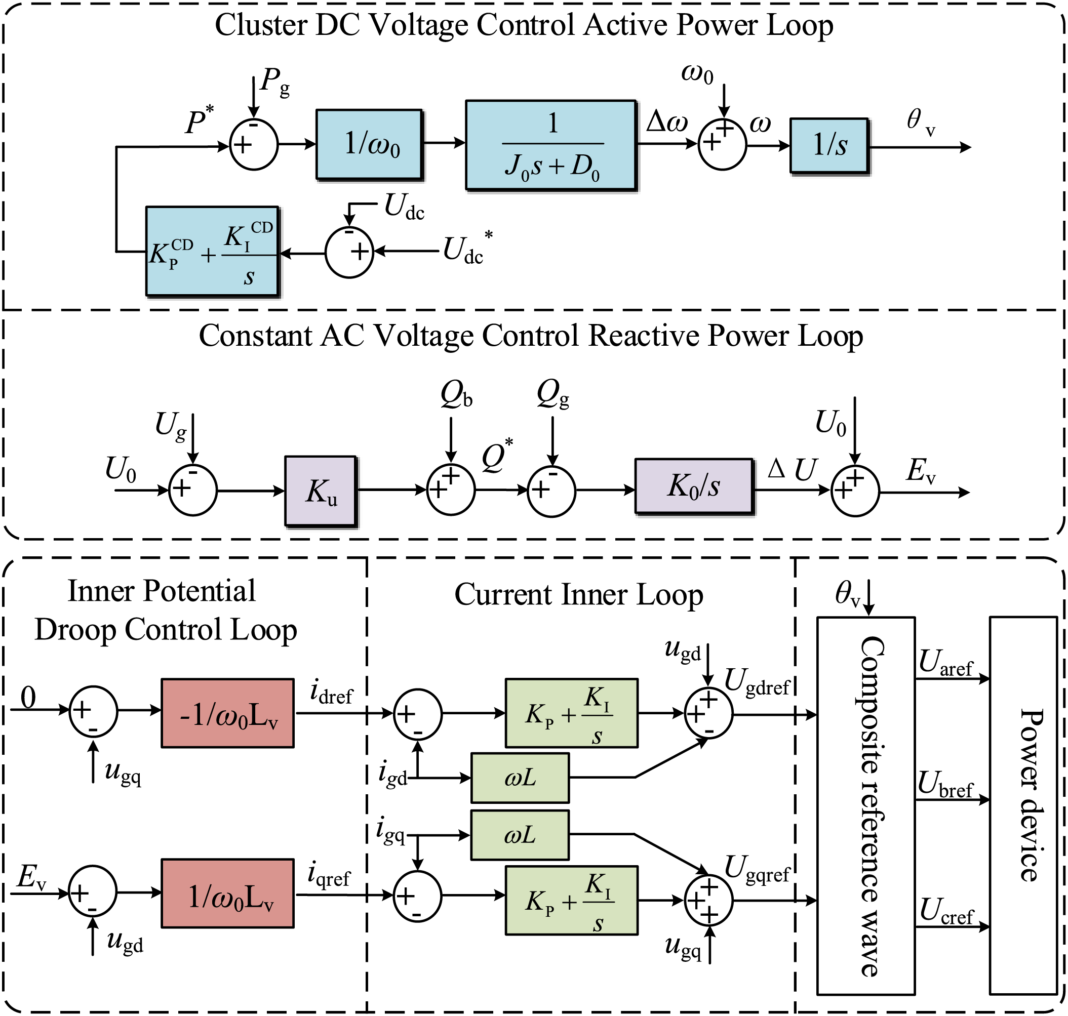
Figure 1: Typical control scheme of GF-SVG
In the constant AC voltage control reactive power loop, U0 is the rated phase voltage, and Ug is the actual phase voltage. The difference between U0 and Ug is calculated. The reactive power adjustment value is obtained by multiplying the difference by the voltage adjustment coefficient Ku. After the reactive power adjustment value is added to the grid-connected reactive power reference Qb to get reactive power command Q*, it is subtracted from the grid-side reactive power Qg. The resulting difference is passed through the integral unit with an integral coefficient K0, which gets a phase voltage adjustment value ΔU. Finally, ΔU is added to U0, and the virtual excitation electromotive force, Ev, is obtained.
GF-SVG does not rely on the traditional phase-locked loop technology and simulates the characteristics of the synchronous condenser to achieve synchronization with the power grid. Therefore, its control robustness is higher under weak grid conditions, which is conducive to the system’s stable operation. As shown in Fig. 1, the cluster DC voltage control active power loop is expressed as Eq. (1).
where Pg is the grid-side active power, P* is the active power reference value, J0 is the virtual inertia coefficient, ω0 is the rated angular frequency, and D0 is the virtual damping coefficient.
Combined with Fig. 1, the constant AC voltage control reactive power loop is expressed as Eq. (2).
The inner potential droop control can be expressed as Eq. (3).
where ugd and ugq are Ug’s d-axis and q-axis components, respectively, Lv is the fixed virtual inductance.
The inner potential droop control generates the reference value of the current inner loop. Then, the three-phase modulation reference voltage Uiref (i represents the A phase, B phase, and C phase) is generated after the current inner loop. The trigger pulse of the power device is generated after the modulation.
2.2 Analysis of the Transient Overcurrent Problem
Due to the long transmission distance, WFs are connected to high-voltage converging stations via overhead lines. Short-circuit faults in these lines can be caused by extreme weather or bird hazards, leading to an overcurrent problem in the GF-SVG within the WFs.
To analyze the overcurrent problem in GF-SVG during the WF fault, the following assumptions are made:
1. The losses of power electronic devices and transmission lines are neglected;
2. During the fault period, the leakage reactance of the grid-connection transformer at the WF voltage drop is neglected. It is approximately assumed that the instantaneous voltage drop at the fault point K in Fig. 2 is equal to the instantaneous voltage drop at Ug.
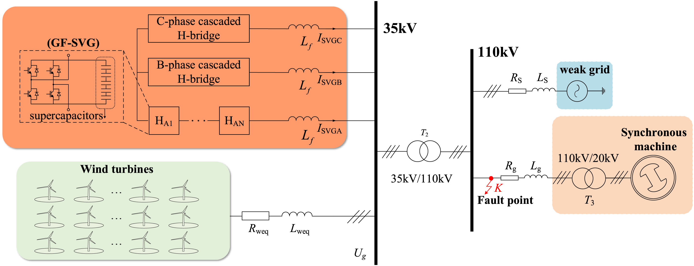
Figure 2: Structure of wind farm system
As can be seen from the structure of the constant AC voltage control reactive power loop shown in Fig. 1, ΔEv can be expressed as Eq. (4).
Because the system has three-phase symmetry during the three-phase short-circuit, only one current phase can be analyzed. The fixed virtual reactance (FVR) Xv and filter reactance Xf between the Ev and the Ug exist. Then, the equivalent output reactance X and the output current |ISVG| of GF-SVG can be expressed as Eq. (5).
where Ev(t0) is the virtual excitation electromotive force at time t0, Zn is the rated impedance of GF-SVG, and Xv∈ (0.1Zn, 0.3Zn).
During the short-circuit fault period, the Ug drops. According to Eq. (4), it can be inferred that ΔEv increases sharply. Combined with Eq. (5), it can be known that the output inductive current |ISVG| of GF-SVG surges. However, after the fault is cleared, under the action of the low-voltage ride-through (LVRT) control of the wind turbine grid-connected converter, the converter still maintains inductive reactive power output in the short term, which leads to an increase in the Ug. Combining Eqs. (4) and (5), it can be concluded that ΔEv decreases sharply to a negative value, the capacitive current |ISVG| of GF-SVG surges after the fault is cleared.
Analysis of Eq. (5) reveals that, since Xf is a constant value, Xv is a crucial factor in determining the |ISVG|. If Xv is relatively small, it will be difficult to suppress the surge in the |ISVG|. If Xv is huge, although it can effectively inhibit overcurrent, it will directly weaken the reactive power compensation capability of GF-SVG.
Accordingly, it is necessary to design an AVR coefficient equation in conjunction with the transient variation trend of the GF-SVG output current, which improves the current dynamic adjustment ability of GF-SVG during fault occurrence and fault recovery.
3 The Current Limitation Method of GF-SVG Based on AVR
3.1 Analysis of the Influence of Virtual Reactance on Control Stability
The regional power grid’s operation short circuit ratio (OSCR) in the wind farm cluster is dynamically changed owing to the influence of wind power output, so the control stability of GF-SVG is stronger than that of GL-SVG. Because the inner potential droop control loop is embedded with virtual reactance, it is necessary to discuss the influence of virtual reactance on stability.
Considering that the response speed of the GF-SVG current inner loop is 10 times that of the power outer loop [21,22]. It will be analyzed from the perspective of the control bandwidth of the current inner loop. The control structure of the current closed loop with virtual reactance is shown in Fig. 3.
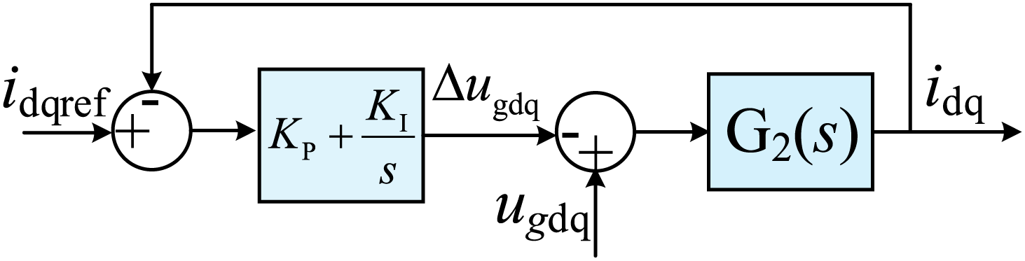
Figure 3: Current closed-loop control
The current inner loop’s open-loop transfer function H1(s) can be expressed as Eq. (6).
where KP and KI are the parameters of the PI controller.
The closed-loop transfer function H2 (s) of the current inner loop can be obtained according to Eq. (6) and Fig. 3, which can be expressed as Eq. (7).
According to Eq. (7), the damping ratio ξ and the overshoot MP of the current closed loop can be expressed as Eq. (8).
The rise time is larger as the ξ is smaller, and the MP will be larger. Accordingly, the larger the virtual reactance, the smaller ξ is, so the current adjustment time becomes longer, and the MP becomes larger.
When KP and KI are constant values, the Bode diagram of different virtual reactance is analyzed to determine the influence of virtual reactance on control stability. Fig. 4 shows that as the virtual reactance increases, the cut-off frequency decreases, the phase margin also decreases, and the stability and robustness of the system decrease.
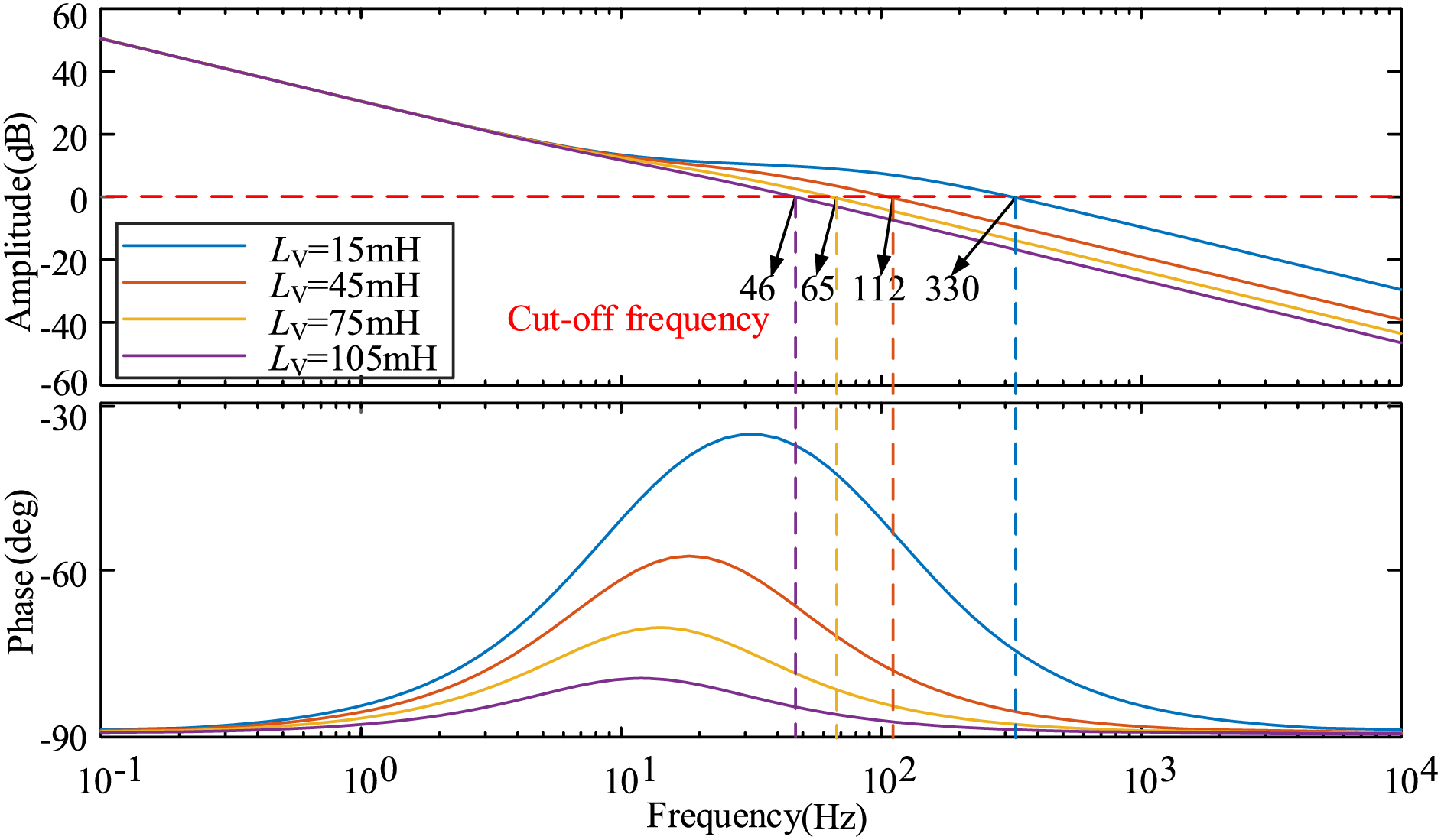
Figure 4: Current open-loop transfer function Bode diagram
3.2 Construction of the Current Limitation Strategy Based on AVR
As mentioned in Sections 2.2 and 3.1, virtual reactance is the main factor affecting the current limitation effect and control stability. An adaptive virtual reactance adjustment method is developed according to the variation of the SVG’s current output to meet the requirement of the current limitation during fault occurrence and clearance in the WF.
The virtual reactance is located in the inner potential droop control loop (Fig. 1), and its initial value should be selected according to GF-SVG’s rated capacity Sn and the U0 [23]. The initial value of AVR is expressed as Eq. (9).
where Ladv0 is the initial value of the adaptive virtual inductance, and Xadv0 is the initial value of the AVR.
In the dq coordinate system, the amplitude of the output phase current of GF-SVG is expressed in Eq. (10).
When the short-circuit fault occurs in the power grid, the AVR trigger coefficient Kon determines whether the GF-SVG enters the adaptive current limitation mode. Kon is expressed as Eq. (11).
where Ith is the current threshold, which is greater than the rated current of GF-SVG and less than its withstand current.
Then, the expression for the AVR is expressed as Eq. (12).
where m is the virtual reactance adjustment coefficient, and ΔI is the extent of current exceeding the threshold. To avoid the adverse impact of the abrupt change in virtual reactance on the current inner loop control, the AVR incorporates an exponential part with e as the base, enabling the virtual reactance to change reasonably according to the ΔI.
As depicted in Fig. 5, the AVR replaces the FVR in the dynamic inner potential droop control loop shown in Fig. 1.
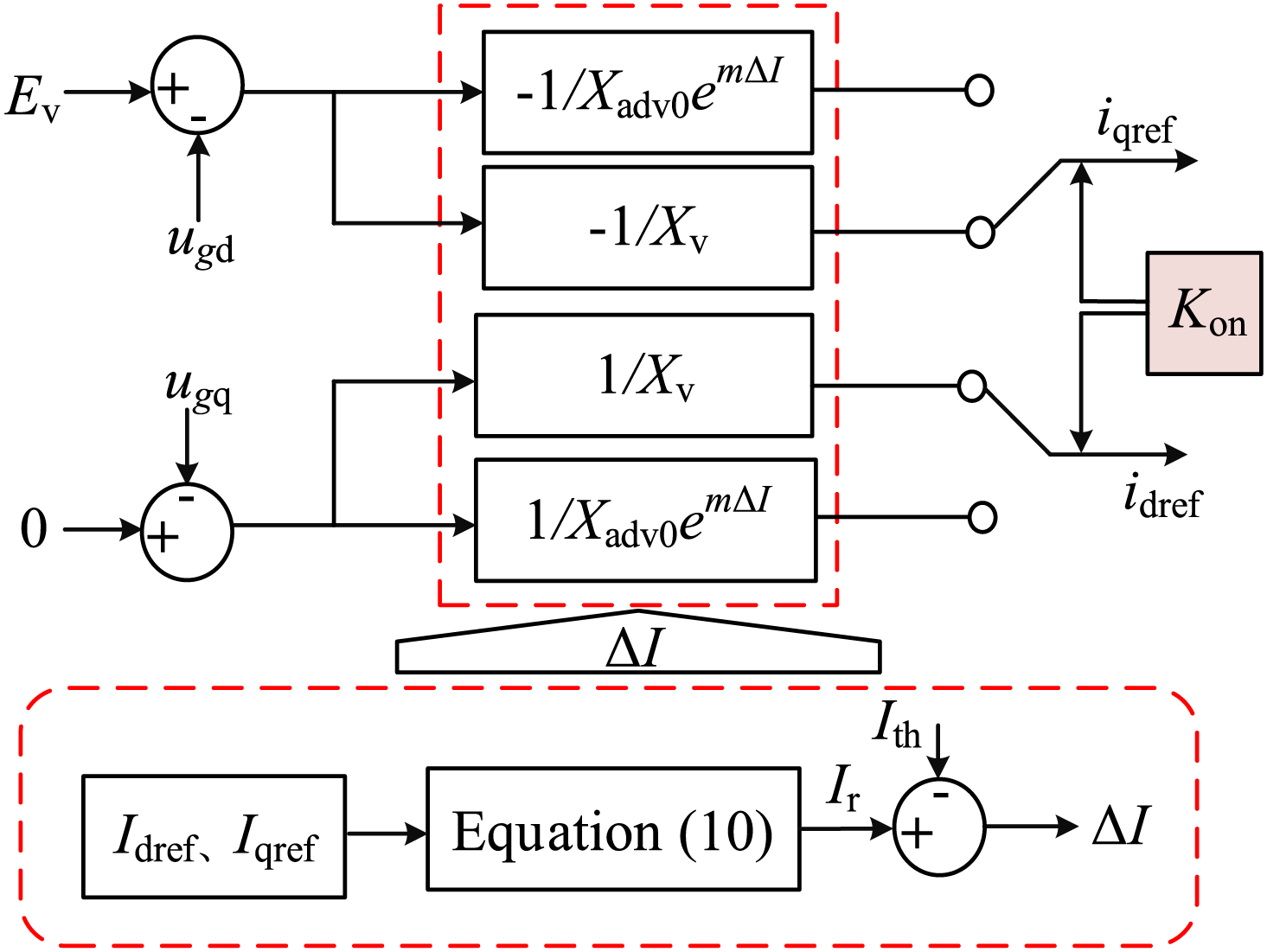
Figure 5: Inner potential droop control loop based on AVR
During the fault occurrence and clearance, the relationship between the output current and the current threshold is judged to determine whether the fault is cleared. If Kon = 1, the GF-SVG adopts AVR control. If Kon = 0, GF-SVG adopts FVR control.
3.3 Calculation of the AVR Adjustment Coefficient
As the analysis of Section 3.2 shows, the AVR is not only related to the ΔI, but also to the m. Combined with Eq. (12), it is necessary to change the m, and then flexibly adjust the virtual reactance.
During the transient overcurrent period, the voltage equation based on AVR’s dynamic internal potential droop control loop is expressed as Eq. (13).
where ΔUv is the voltage drop across the virtual reactance, and Ikmax is the maximum value of the transient overcurrent.
By simplifying Eq. (13), m can be expressed as Eq. (14).
Eq. (14) shows that with the dynamic change in ΔUv and Ikmax, the m correspondingly changes to adjust the value of the virtual reactance, thereby achieving the current limitation.
4 Influence of AVR on AC/DC Voltage
4.1 Inhibitory Effect of Virtual Reactance on DC Voltage Drop
From the perspective of transient voltage support, when a short-circuit fault occurs in the power grid, the grid-side voltage drops, and the DC-side voltage of GF-SVG decreases. However, when the DC side voltage drop is severe, it will weaken the reactive power support capability of GF-SVG. To analyze the inhibitory effect of virtual reactance on the DC side voltage drop, firstly, according to the cluster DC voltage active loop structure in Fig. 1, the small signal model of the active loop is established, and its structure is shown in Fig. 6.
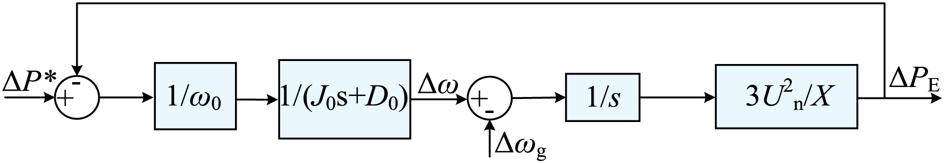
Figure 6: Small signal model of active power loop for GF-SVG based on AVR
Ignoring the grid-side frequency disturbance, that is, Δωg = 0. The transfer function of the small signal model of the active power loop is expressed as Eq. (15).
When ΔP* is a step variation, Eq. (16) is expressed as:
Eq. (16) shows that when a short-circuit fault occurs, the DC side cluster voltage decreases from Udc0 to UdcF, and ΔPE can be expressed as Eq. (17).
where Cdc is a submodule of supercapacitor capacitance.
By simplifying Eq. (17), UdcF can be expressed as Eq. (18).
According to Eqs. (16)–(18), it can be known that during the fault occurrence, as the virtual reactance increases, ΔPE will decrease, and the UdcF increases. Compared with the FVR, the proposed AVR current limitation method significantly reduces the DC voltage drop.
4.2 The Positive Effect of Virtual Reactance on AC Voltage Recovery
A small signal model of GF-SVG’s reactive power-voltage control loop is established in Fig. 7 to analyze the positive impact of virtual reactance on AC voltage recovery.
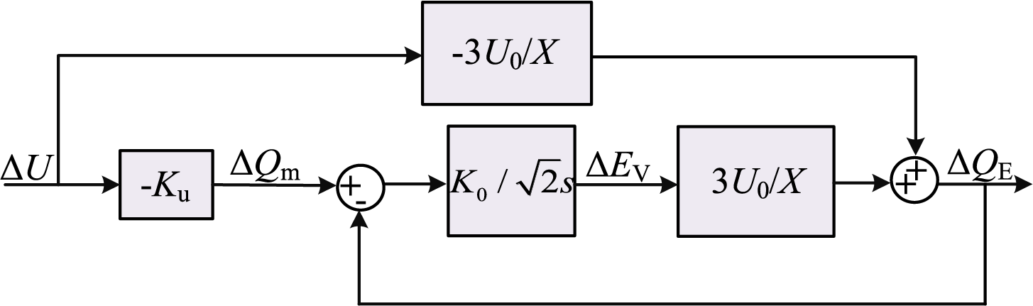
Figure 7: Small signal model of reactive power loop for GF-SVG based on AVR
Based on Fig. 7, the transfer function of the reactive power-voltage control loop for GF-SVG with AVR can be expressed as Eq. (19).
According to Eq. (19), the one-step time constant Tq is expressed as Eq. (20).
Eq. (19) shows that the closed-loop transfer function of reactive power-voltage control of GF-SVG is a first-step function. The larger the Tq, the longer it takes for the output reactive power of GF-SVG to reach the target value.
Based on the WF system simulation model established in Section 2.1 and in conjunction with the simulation parameters provided in Table 1, the simulation result of the reactive power output of GF-SVG with AVR control or FVR control is compared after the short-circuit fault at point K is cleared, as shown in Fig. 8.
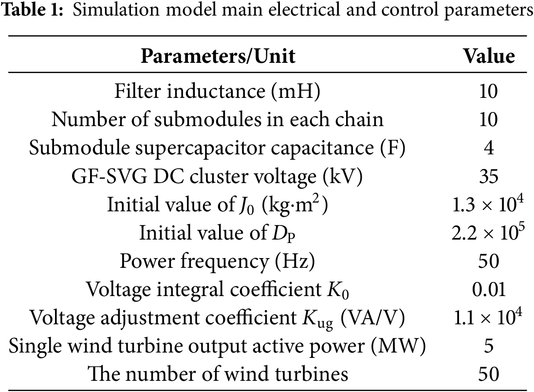
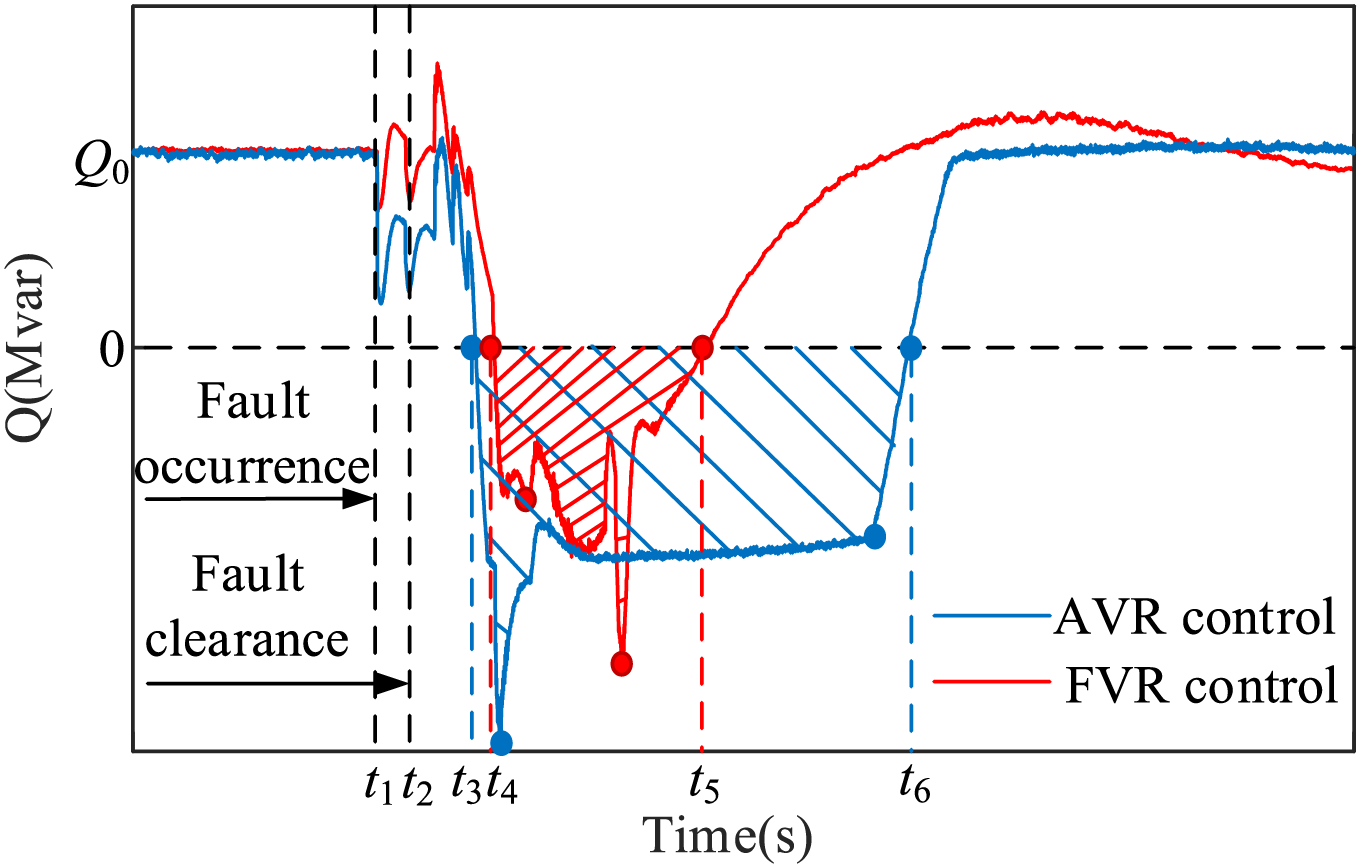
Figure 8: The comparison diagram of the output reactive power of GF-SVG
Compared with using FVR (as indicated by the red shaded area), the GF-SVG using AVR from t3 to t6 can absorb more inductive reactive power from the wind turbines (as indicated by the blue shaded area), so transient overvoltage recoveries rapidly.
5.1 Simulation Parameter Settings and Conditions
To validate the effectiveness of the proposed method for GF-SVG based on AVR, an electromagnetic simulation model of the WF system incorporating GF-SVG is established based on the WF structure shown in Fig. 2.
5.2 Simulation Results Analysis
The location of the fault point K is shown in Fig. 2. The three-phase symmetrical fault occurs at 7 s and is cleared at 7.02 s. The threshold current is set as Ith = 3In. FVR control and AVR control are respectively employed for current limitations. The simulation analysis results are as follows:
(1) Analysis of the current limiting effect
The variation trends of the output current of the GF-SVG and the virtual inductance are shown in Fig. 9. As can be seen from Fig. 9a, when only FVR control is used for current limitation, the transient overcurrent is serious during the fault occurrence and the fault clearance. At about 7.05 s, the ΔI reaches approximately 3599 A. In contrast, when the AVR current limitation method is applied at about 7.02 s, analysis of Fig. 9b reveals that, compared to the FVR control, the output current of GF-SVG is confined within the current threshold range (−3In~3In) during the fault occurrence and the fault clearance. Meanwhile, as shown in Fig. 9c, the virtual inductance adaptively adjusts according to the current variation during the fault occurrence and the fault clearance, and the output current fluctuation of GF-SVG is rapidly suppressed. Around 7.05 s, the increment of the virtual inductance is approximately 78 mH.
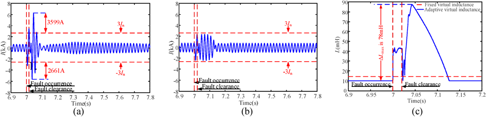
Figure 9: Comparison of output current and virtual inductance variation for two current limitation methods in GF-SVG. (a) The phase current output by GF-SVG controlled by FVR; (b) The phase current output by GF-SVG controlled by AVR; (c) Comparison of fixed virtual inductance and adaptive virtual inductance
(2) Analysis of the overvoltage recovery effect in the WF
Fig. 10a shows that when FVR control is used for current limitation, the wind turbines still maintain inductive reactive power output for a short period after the fault is cleared, resulting in an overvoltage duration of approximately 38 ms. In contrast, with AVR control, the system voltage recovery process is shown in Fig. 10b, in which the overvoltage duration is reduced to 25 ms.
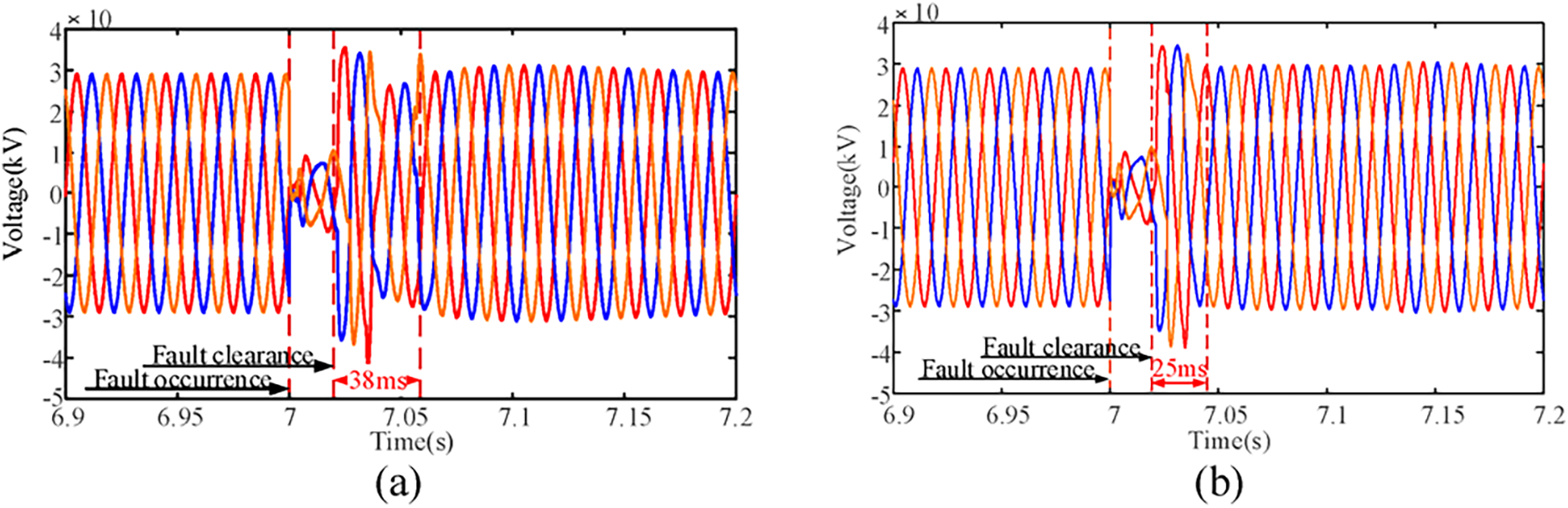
Figure 10: Comparison of transient overvoltage in the WF system under two types of current limitation control for GF-SVG. (a) The output voltage of GF-SVG controlled by FVR; (b) The output voltage of GF-SVG controlled by AVR
(3) DC voltage variation analysis for GF-SVG
Fig. 11a,b shows that the DC voltage drop of GF-SVG with AVR control in 7~7.1 s is significantly smaller than that of GF-SVG with FVR control. The maximum DC voltage drop of GF-SVG with FVR control is about 2880 V. By comparison, the maximum DC voltage drop of GF-SVG with AVR control is about 500 V.
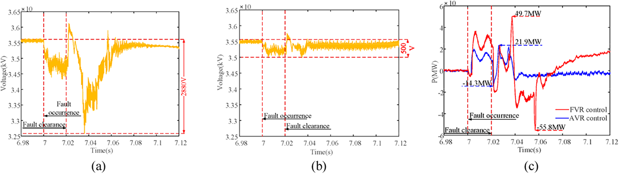
Figure 11: Comparison of DC voltage and active output of GF-SVG under two current limitation methods. (a) The cluster DC voltage of GF-SVG controlled by FVR; (b) The cluster DC voltage of GF-SVG is controlled by AVR; (c) The transient output active power of GF-SVG
After the fault occurs, the output active power variation of GF-SVG under the two current limitation methods is shown in Fig. 11c. The maximum active power output of GF-SVG with FVR control is about 49.7 MW. By comparison, GF-SVG with AVR control’s maximum active power output is about 21.9 MW. The maximum active power absorbed by GF-SVG with FVR control is about 55.8 MW. By comparison, the maximum active power absorbed by GF-SVG with AVR control is about 14.3 MW. The fluctuation of the active power output of GF-SVG with AVR control is smaller than that of the FVR control in 6.98~7.12 s.
The location of the fault point K is shown in Fig. 2. The three-phase symmetrical fault occurs at 7 s and is cleared at 7.01 s. The threshold current is set as Ith = 1.5In. FVR control and AVR control are respectively employed for current limitations. The simulation analysis results are as follows:
(4) Analysis of the current limiting effect
The variation trends of the output current of the GF-SVG and the virtual inductance are shown in Fig. 12. As can be seen from Fig. 12a, when only FVR control is used for current limitation, the transient overcurrent is serious during the fault occurrence and the fault clearance. At about 7.04 s, the ΔI reaches approximately 3378 A. In contrast, when the AVR current limitation method is applied at about 7.01 s, analysis of Fig. 12b reveals that, compared to the FVR control, the output current of GF-SVG is confined within the current threshold range (−1.5In~1.5In) during the fault occurrence and the fault clearance. Meanwhile, as shown in Fig. 12c, the virtual inductance adaptively adjusts according to the current variation during the fault occurrence and the fault clearance, and the output current fluctuation of GF-SVG is rapidly suppressed. Around 7.05 s, the increment of the virtual inductance is approximately 101 mH.
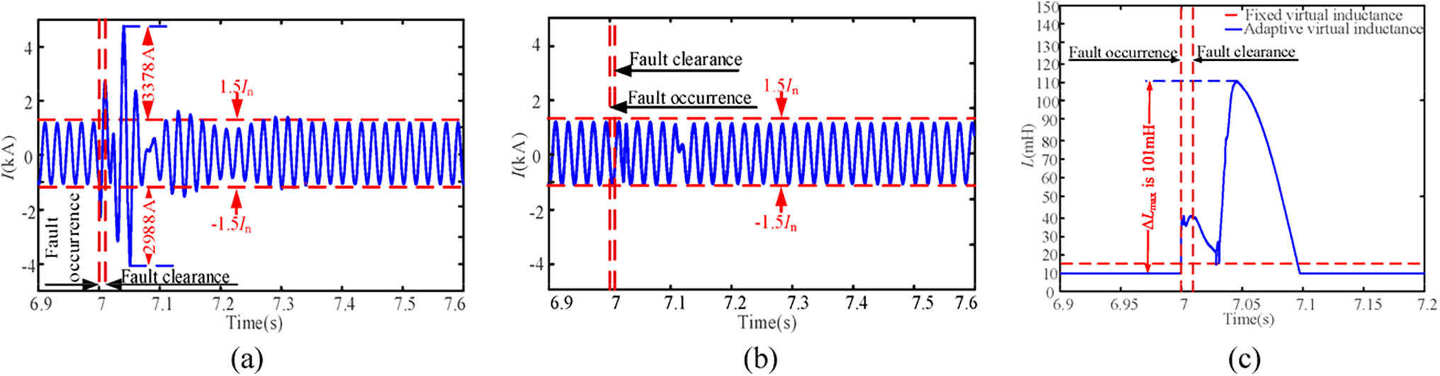
Figure 12: Comparison of output current and virtual inductance variation for two current limitation methods in GF-SVG. (a) The phase current output by GF-SVG controlled by FVR; (b) The phase current output by GF-SVG controlled by AVR; (c) Comparison of fixed virtual inductance and adaptive virtual inductance
(5) Analysis of the overvoltage recovery effect in the WF
It can be seen from Fig. 13a, that when FVR control is used for current limitation, the wind turbines still maintain inductive reactive power output for a short period after the fault is cleared, resulting in an overvoltage duration of approximately 45 ms. In contrast, with AVR control, the system voltage recovery process is shown in Fig. 13b, in which the overvoltage duration is reduced to 22 ms.
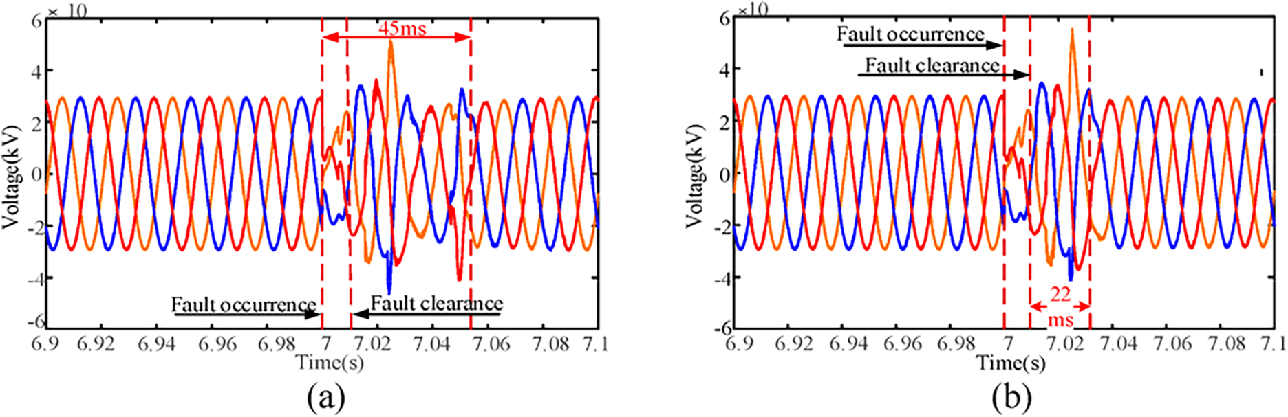
Figure 13: Comparison of transient overvoltage in the WF system under two types of current limitation control for GF-SVG. (a) The output voltage of GF-SVG is using the FVR control; (b) The output voltage of GF-SVG is using the AVR
(6) DC voltage variation analysis for GF-SVG
It can be seen from Fig. 14a,b that the DC voltage drop of GF-SVG with AVR control in 7~7.12 s is significantly smaller than GF-SVG with FVR control. The maximum DC voltage drop of GF-SVG with FVR control is about 1720 V. By comparison, the maximum DC voltage drop of the GF-SVG with AVR control is about 560 V.
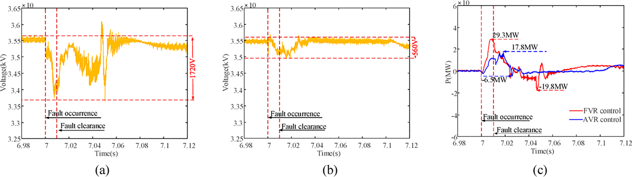
Figure 14: Comparison of DC voltage and active output of GF-SVG under two current limitation methods. (a) The cluster DC voltage of GF-SVG controlled by FVR control; (b) The cluster DC voltage of GF-SVG is controlled by AVR control. (c) The transient output active power of GF-SVG
After the fault occurs, the output active power variation of GF-SVG under the two current limitation methods is shown in Fig. 14c. The maximum active power output of GF-SVG with FVR control is about 29.3 MW. By comparison, GF-SVG with AVR control’s maximum active power output is about 17.8 MW. The maximum active power absorbed by GF-SVG with FVR control is about 19.8 MW. By comparison, the maximum active power absorbed by GF-SVG with AVR control is about 6.5 MW. The fluctuation of the active power output of GF-SVG with AVR control is smaller than that of the FVR control in 6.98~7.12 s.
During the fault occurrence and recovery in the WF system, the GF-SVG exists the transient overcurrent problem. A current limitation method for GF-SVG is proposed to address the issue based on the AVR. The following conclusions are drawn:
(1) By analyzing the open-loop transfer function of the current loop containing the virtual reactance, it is found that as the virtual reactance increases, the phase margin of GF-SVG gradually decreases, decreasing GF-SVG control stability.
(2) Although the FVR’s current limitation method can realize the GF-SVG’s current limitation, it can not be reasonably adjusted according to the extent of the current over-limit when the fault occurs. Thus, the current limitation of GF-SVG during the fault occurrence and the fault recovery is not ideal.
(3) The proposed AVR current limitation method can effectively address the transient overcurrent problem of GF-SVG during fault occurrence and fault recovery by adjusting the virtual reactance in real-time according to the transient variation trend of the output current of the GF-SVG.
(4) During the fault occurrence and the fault recovery stage, for the system overvoltage problem caused by the LVRT, compared with the FVR current limitation method, the AVR current limitation method can not only improve the recovery speed of the transient overvoltage after the fault clearance but also effectively suppress the DC voltage drop of GF-SVG.
(5) Due to methodological constraints, the study primarily addresses adaptive current limitations for three-phase symmetric faults. The analytical framework adopted does not readily extend to asymmetric fault conditions. To address these limitations, we will refine the analytical framework and conduct in-depth research in our subsequent studies.
Acknowledgement: The authors thank the editor and anonymous reviewers for their reviews and valuable comments.
Funding Statement: This paper is supported by the National Natural Science Foundation of China under Grant 52077030.
Author Contributions: The authors confirm contribution to the paper as follows: study conception and design: Jikai Chen, Haoru Li; data collection: Jiayang Zhang; analysis and interpretation of results: Shuangshuang Yao, Qianxin Li; draft manuscript preparation: Jiawei Wang. All authors reviewed the results and approved the final version of the manuscript.
Availability of Data and Materials: Data supporting this study are included within the article.
Ethics Approval: Not applicable.
Conflicts of Interest: The authors declare no conflicts of interest to report regarding the present study.
Glossary
| GF-SVG | Grid Forming Static Var Generator |
| GL-SVG | Grid Following Static Var Generator |
| FVR | Fixed Virtual Reactance |
| AVR | Adaptive Virtual Reactance |
| WF | Wind Farm |
References
1. Wang Y, Song Y, Liao J, Zeng Q. Review and development trends of DFIG-based wind power voltage active support technology. Power Syst Technol. 2023;47(8):3193–205. doi:10.13335/j.1000-3673.pst.2022.1304. [Google Scholar] [CrossRef]
2. Chen GP, Dong Y, Liang ZF. Analysis and reflection on high-quality development of new energy with Chinese characteristics in energy transition. Proc CSEE. 2020;40(17):5493–505. doi:10.13334/j.0258-8013.pcsee.200984. [Google Scholar] [CrossRef]
3. Taul MG, Wang X, Davari P, Blaabjerg F. An overview of assessment methods for synchronization stability of grid-connected converters under severe symmetrical grid faults. IEEE Trans Power Electron. 2019;34(10):9655–70. doi:10.1109/TPEL.2019.2892142. [Google Scholar] [CrossRef]
4. Vasudevan KR, Ramachandaramurthy VK, Babu TS, Pouryekta A. Synchronverter: a comprehensive review of modifications, stability assessment, applications, and future perspectives. IEEE Access. 2020;8:131565–89. doi:10.1109/ACCESS.2020.3010001. [Google Scholar] [CrossRef]
5. Askarov A, Ruban N, Bay Y, Ufa R, Malkova Y, Suvorov A. A feedforward control for increasing the damping effect of enhanced current-controlled virtual synchronous generator. Electr Power Syst Res. 2024;234(3):110659. doi:10.1016/j.epsr.2024.110659. [Google Scholar] [CrossRef]
6. Zhang JW, Zhang C, Shi XQ, Zhang Y, Huang L, Cai X. Energy-storage-type static var generator and its autonomous-synchronization voltage source control. High Volt Eng. 2023;49(1):61–71. doi:10.13336/j.1003-6520.hve.20220576. [Google Scholar] [CrossRef]
7. He X, Geng H, Xi J, Guerrero JM. Resynchronization analysis and improvement of grid-connected VSCs during grid faults. IEEE J Emerg Sel Top Power Electron. 2019;9(1):438–50. doi:10.1109/JESTPE.2019.2954555. [Google Scholar] [CrossRef]
8. Li Z, Chan KW, Hu J, Or SW. An adaptive fault ride-through scheme for grid-forming inverters under asymmetrical grid faults. IEEE Trans Ind Electron. 2021;69(12):12912–23. doi:10.1109/TIE.2021.3135641. [Google Scholar] [CrossRef]
9. Bottrell N, Green TC. Comparison of current-limiting strategies during fault ride-through of inverters to prevent latch-up and wind-up. IEEE Trans Power Electron. 2013;29(7):3786–97. doi:10.1109/TPEL.2013.2279162. [Google Scholar] [CrossRef]
10. Liu H, Wang Y, Liu Y, Peng Y, Li M, Lei W. The LVRT strategy for VSG based on the quantitatively designed virtual impedance. High Volt Eng. 2022;48(1):245–56. doi:10.13336/j.1003-6520.hve.20210830. [Google Scholar] [CrossRef]
11. Wang XM, Wang YB, Liu YT, Liu C, Wang SJ, Hu B. Low voltage ride-through control of actively-supported new energy unit based on virtual reactance. Power Syst Technol. 2022;46(11):4435–44. doi:10.13335/j.1000-3673.pst.2021.2148. [Google Scholar] [CrossRef]
12. Fan B, Liu T, Zhao F, Wu H, Wang X. A review of current-limiting control of grid-forming inverters under symmetrical disturbances. IEEE Open J Power Electron. 2022;3:955–69. doi:10.1109/OJPEL.2022.3227507. [Google Scholar] [CrossRef]
13. Koiwa K, Inoo K, Zanma T, Liu KZ. Virtual voltage control of VSG for overcurrent suppression under symmetrical and asymmetrical voltage dips. IEEE Trans Ind Electron. 2021;9(11):11177–86. doi:10.1109/TIE.2021.3125654. [Google Scholar] [CrossRef]
14. Qoria T, Gruson F, Colas F, Denis G. Critical clearing time determination and enhancement of grid-forming converters embedding virtual impedance as current limitation algorithm. IEEE J Emerg Sel Top Power Electron. 2019;8(2):1050–61. doi:10.1109/JESTPE.2019.2959085. [Google Scholar] [CrossRef]
15. Wang D, Yin Q, Wang H, Chen J, Miao H, Chen Y. Improve strategy for transient power angle stability control of VSG combining frequency difference feedback and virtual impedance. Energy Eng. 2025;122(2):651–66. doi:10.32604/ee.2025.057670. [Google Scholar] [CrossRef]
16. Qoria T, Wu H, Wang X, Colak I. Variable virtual impedance-based overcurrent protection for grid-forming inverters: small-signal, large-signal analysis and improvement. IEEE Trans Smart Grid. 2022;14(5):3324–36. doi:10.1109/TSG.2022.3232987. [Google Scholar] [CrossRef]
17. Wu H, Wang X, Zhao L. Design considerations of current-limiting control for grid-forming capability enhancement of VSCs under large grid disturbances. IEEE Trans Power Electron. 2024;39(10):12081–5. doi:10.1109/TPEL.2024.3350912. [Google Scholar] [CrossRef]
18. Paquette AD, Divan DM. Virtual impedance current limiting for inverters in microgrids with synchronous generators. IEEE Trans Ind Appl. 2014;51(2):1630–8. doi:10.1109/TIA.2014.2345877. [Google Scholar] [CrossRef]
19. Yousaf MZ, Koondhar MA, Zaki ZA, Ahmed EM, Alaas ZM, Mahariq I, et al. Improved MPPT of solar PV systems under different environmental conditions utilizes a novel hybrid PSO. Renew Energy. 2025;244(2):122709. doi:10.1016/j.renene.2025.122709. [Google Scholar] [CrossRef]
20. Yousaf MZ, Singh AR, Khalid S, Bajaj M, Kumar BH, Zaitsev I. Bayesian-optimized LSTM-DWT approach for reliable fault detection in MMC-based HVDC systems. Sci Rep. 2024;14(1):17968. doi:10.1038/s41598-024-68985-5. [Google Scholar] [PubMed] [CrossRef]
21. Shuai Z, Shen C, Liu X, Li Z, Shen ZJ. Transient angle stability of virtual synchronous generators using Lyapunov’s direct method. IEEE Trans Smart Grid. 2018;10(4):4648–61. doi:10.1109/TSG.2018.2866122. [Google Scholar] [CrossRef]
22. Chen S, Sun Y, Hou X, Han H, Fu S, Su M. Quantitative parameters design of VSG oriented to transient synchronization stability. IEEE Trans Power Syst. 2023;38(5):4978–81. doi:10.1109/TPWRS.2023.3293016. [Google Scholar] [CrossRef]
23. Taul MG, Wang XF, Davari P, Blaabjerg F. Current limiting control with enhanced dynamics of grid-forming converters during fault conditions. IEEE J Emerg Sel Top Power Electron. 2020;8(2):1062–73. doi:10.1109/JESTPE.2019.2931477. [Google Scholar] [CrossRef]
Cite This Article
 Copyright © 2025 The Author(s). Published by Tech Science Press.
This work is licensed under a Creative Commons Attribution 4.0 International License , which permits unrestricted use, distribution, and reproduction in any medium, provided the original work is properly cited.
 Downloads
 Citation Tools