
 Submit a Paper
 Propose a Special lssue
 Open Access
ARTICLE

Unravelling Temperature Profile through Bifacial PV Modules via Finite Difference Method: Effects of Heat Internal Generation Due to Spectral Absorption
Electronics and Optics of Semiconductor Nanostructures and Sustainable Energy Team, Laboratory of Instrumentation of Measure and Control, Department of Physics, Faculty of Sciences, Chouaïb Doukkali University (UCD), El Jadida, P.O. Box 20, Morocco
* Corresponding Author: El Mahdi Assaid. Email:
(This article belongs to the Special Issue: Modelling, Optimisation and Forecasting of Photovoltaic and Photovoltaic thermal System Energy Production)
Energy Engineering 2025, 122(9), 3487-3505. https://doi.org/10.32604/ee.2025.067422
Received 03 May 2025; Accepted 07 July 2025; Issue published 26 August 2025
 View Full Text
 Download PDF
Abstract
This study investigates the complex heat transfer dynamics in multilayer bifacial photovoltaic (bPV) solar modules under spectrally resolved solar irradiation. A novel numerical model is developed to incorporate internal heat generation resulting from optical absorption, grounded in the physical equations governing light-matter interactions within the module’s multilayer structure. The model accounts for reflection and transmission at each interface between adjacent layers, as well as absorption within individual layers, using the wavelength-dependent dielectric properties of constituent materials. These properties are used to calculate the spectral reflectance, transmittance, and absorption coefficients, enabling precise quantification of internal heat sources from irradiance incidents on both the front and rear surfaces of the module. The study further examines the influence of irradiance reflection on thermal behavior, evaluates the thermal impact of various supporting materials placed beneath the module, and analyzes the role of albedo in modifying heat distribution. By incorporating spectrally resolved heat generation across each layer often simplified or omitted in conventional models, the proposed approach enhances physical accuracy. The transient heat equation is solved using a one-dimensional finite difference (FD) method to produce detailed temperature profiles under multiple operating scenarios, including Standard Test Conditions (STC), Bifacial Standard Test Conditions (BSTC), Normal Operating Cell Temperature (NOCT), and Bifacial NOCT (BNOCT). The results offer valuable insights into the interplay between optical and thermal phenomena in bifacial systems, informing the design and optimization of more efficient photovoltaic technologies.Keywords
The growing demand for clean energy has led to significant advancements in photovoltaic PV technologies [1], including the development of bifacial photovoltaic bPV modules. These modules can absorb light from both the front and rear surfaces, offering higher energy yields compared to conventional monofacial modules [2–4]. The performance of bPV systems is strongly influenced by environmental and thermal conditions, making thermal modeling an essential tool for optimizing their efficiency and deployment.
Several studies have investigated the thermal behavior of PV modules using both experimental and numerical approaches. Many rely on simplified models that assume uniform heat generation and constant material properties, which may not accurately capture real-world operating conditions [3,5–8]. More advanced work has focused on multilayer heat transfer analysis using finite difference and finite element methods, as in [5,9–11], where internal heat generation and boundary heat exchange are considered. However, these models often treat heat sources as uniform or empirical, without resolving how spectral absorption in each layer contributes to temperature profiles.
Recent advances in PV simulation have emphasized the need to incorporate both optical and thermal phenomena into the modeling framework. For instance, Abo-Zahhad et al. [12] developed a three-dimensional transient model that considers spectral irradiance and local temperature distribution, highlighting the impact of spatial and optical effects on thermal behavior. Similarly, other researchers have combined optical-electrical-thermal simulations to investigate localized heating, degradation, and system efficiency under real-world conditions [7,8,13].
This study introduces a novel approach that accounts for internal heat generation due to optical absorption in bPV modules, incorporating the interaction between light and matter at each interface within their multilayer structure. By solving the heat equation under dynamic conditions using a one-dimensional finite difference (FD) method, we generate detailed temperature profiles for various operational scenarios, offering a deeper understanding of the thermal behavior essential for optimizing module design. The research also investigates the influence of albedo, quantified by a coefficient ranging from 0 to 1, on the performance of bPV modules. Albedo plays a key role in determining the amount of reflected irradiance that bPV modules receive from surrounding surfaces. By modeling environmental variations through the albedo coefficient, the study examines its impact on key performance factors such as the maximum power point and efficiency. The findings provide valuable insights for optimizing the design and operation of bPV systems under different environmental conditions.
The results provide a deeper understanding of the thermal behavior of bPV modules and highlight the importance of optical design, albedo selection, and thermal management for maximizing power output and system reliability.
This section presents the mathematical framework used to model heat transfer in multilayer bPV modules. The model couples optical absorption with internal heat generation and applies a finite difference method to solve the 1D transient heat equation. The structure, material properties, heat sources, and boundary conditions are described in detail to provide a clear understanding of the energy flow within the module under real-world irradiance.
2.1 Structural Composition of bPV Modules
Different technologies of bPV modules consist of various layer compositions. The PV panel examined in this study has five layers as presented in Fig. 1. The module begins with a top glass layer, made of tempered glass, which provides mechanical protection and allows sunlight to pass through to the internal components. Beneath the glass is the top encapsulant layer, composed of Ethylene-Vinyl Acetate (EVA), which securely laminates the bPV cells and protects them from mechanical stress. At the core of the module are the PV cells, which are responsible for converting sunlight into electrical energy. These cells are encapsulated by a bottom EVA layer, similar to the top encapsulant, to ensure uniform protection and structural integrity. Finally, the module is enclosed by a bottom glass layer, which, in bifacial designs, is transparent to allow sunlight to enter from both rear and front sides [14]. In this study, the panel is tilted at a specific angle to optimize its performance.
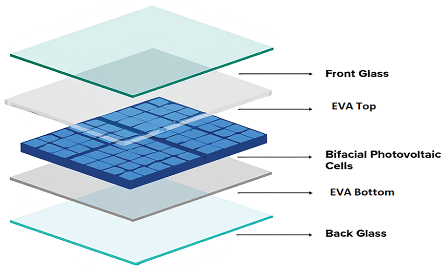
Figure 1: Structural composition of PV modules
2.2 Materials, Optical Absorptions, Internal Heat Sources, and Heat Transfer Dynamics
The core equation describing spatiotemporal behavior of heat transfer in a single spatial dimension
here
2.2.2 Internal Heat Generation
In bPV modules, internal heat generation within passive layers arises from the absorption of incoming light impinging on the front face as well as albedo impacting the rear face. When light enters through the front face, the absorption path varies across the layers of the module, from top glass to bottom glass, as each layer interacts with the incoming radiation differently. Similarly, when light is reflected on the rear face, absorption and subsequent heat generation follow a reversed path, starting from the bottom glass and progressing to the top [3]. Understanding heat generation in both scenarios is crucial for accurately modeling the thermal behavior of each layer in the bPV module. The following equations describe the heat transfer mechanisms and internal heat sources for each layer in the module under both front- and rear-illumination conditions.
Within each layer,
2.2.3 Thermal Diffusion Modes Involved in the Heat Equation
Heat generated inside the module is dissipated through three primary modes: conduction within the layers, convection to ambient air, and radiation to the sky and ground. Each mode is described mathematically below.
Thermal Conduction Mode
Thermal conduction is the mechanism by which heat spreads due to a temperature gradient occurring either within a single material or at the interface between two adjacent materials, without involving movement of matter [8,13].
here
Thermal Convection Mode
Heat convection in bPV modules refers to heat transfer between the module front and rear surfaces on the one hand and the surrounding air on the other hand [8]. This process depends on the temperature difference
Convection can occur under either natural or forced conditions. The overall convection coefficient is expressed as [6]:
where
where
where
The forced convection coefficient is obtained using the following formula [5]:
Thermal Radiation Mode
Heat transfer via radiation occurs between the bPV module front surface and the sky on one hand and between the bPV module rear surface and the ground on the other hand. This process is modeled using the Stefan-Boltzmann law, consistent with prior applications in PV thermal studies [3,20]:
2.3 One-Dimensional Finite Difference Solution of the Heat Equation
To solve the heat equation numerically, the spatial domain is discretized across five distinct layers. A finite difference scheme is applied using an implicit formulation to ensure stability and accuracy over time.
Eq. (1) is a one-dimensional second-order time-dependent partial differential equation defined in a non-homogeneous medium, which is a superposition of five homogeneous media (m = 1 to 5). In each medium, Eq. (1) is discretized on Mm points of a uniform spatial mesh. In each point
Discretizing Eq. (1) in a grid such as
where
The thermophysical parameter
Applying the stencil given in Eq. (23) to all nodes of the grid leads to a system of M equations with M unknowns
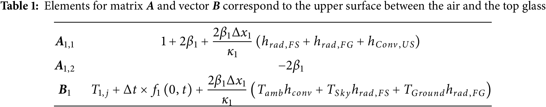
On the front surface (m = 1), a mixed boundary condition is applied:
which leads to the equation given by substituting this expression into the stencil given in Eq. (1). This enables the elements of matrix A and vector B corresponding to the upper surface to be identified, as presented in Table 1.
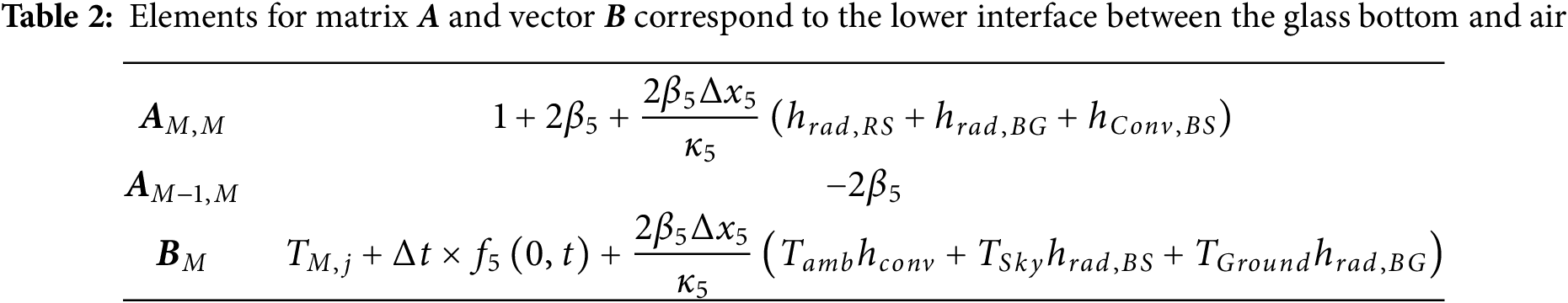
On the rear surface (m = 5), a similar boundary condition is applied to obtain
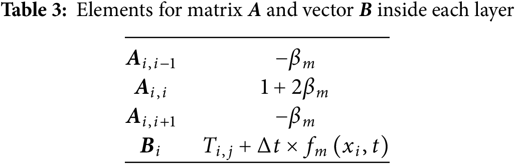
For the internal nodes across all module layers, applying the stencil from Eq. (23) yields the matrix elements summarized in Table 3 below:
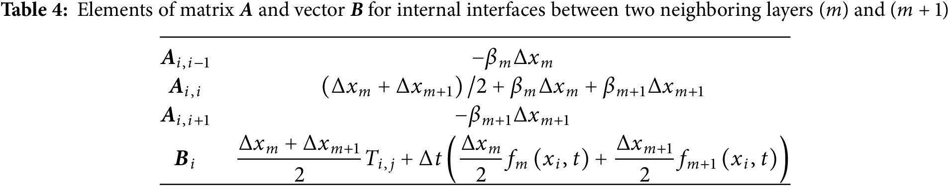
Concerning the nodes at four internal interfaces between two neighboring materials, the discretization of the heat equation leads to the following stencil:
The corresponding matrix A and vector B elements are gathered in Table 4.
The matrix resulting from this approach was solved using the FD method. The resulting linear system in Eq. (24) is solved iteratively at each time step to obtain the temperature profile across the module depth.
2.4 Electricity Generation in Bifacial PV Modules
The power at maximum power point (MPP)
where is the power at MPP under Standard Test Conditions (STC),
where
2.5 Impact of Albedo on Maximum Power and Efficiency of Bifacial PV Modules
The efficiency of a bifacial photovoltaic module is significantly influenced by the albedo coefficient [3]. The total incident power
where
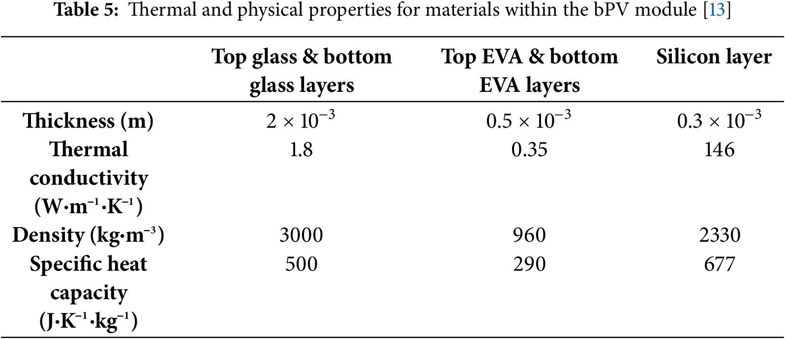
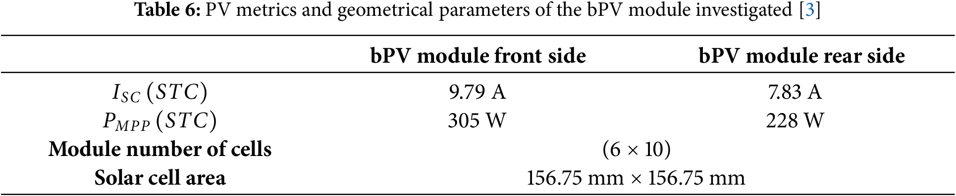
In this work, we focus on a bPV module with a Silicon active layer. Table 5 gathers geometrical and physical properties of layers forming the bPV module. Table 6 provides PV metrics and some specifications of the bPV module investigated.
3.1 Internal Heat Generation in bPV Layers under Incident Irradiation in the Direction of Front and Rear Faces
To evaluate the thermal behavior within the bPV module, the spatial distribution of internally generated heat was determined using expressions in Eqs. (2)–(6) that integrate optical, electrical, and thermal properties of each layer. The proposed model introduces several key improvements over existing thermal modeling approaches. It accounts for spectrally resolved heat generation in each individual layer, unlike many studies that assume constant generation in the active layer or neglect heat generation in passive layers entirely [6]. This level of detail enhances both the physical accuracy and the practical relevance of the simulation, particularly for analyzing the thermal behavior of bifacial PV modules. The analysis considers reflection, transmission at interfaces between adjacent materials, and absorption within each layer. The graphs in Fig. 2 illustrate the variation of heat generation in each layer as a function of thickness under two scenarios: when incident light enters from its front face and when light reflected by the environment behind the PV module enters from its rear face for different albedo conditions.
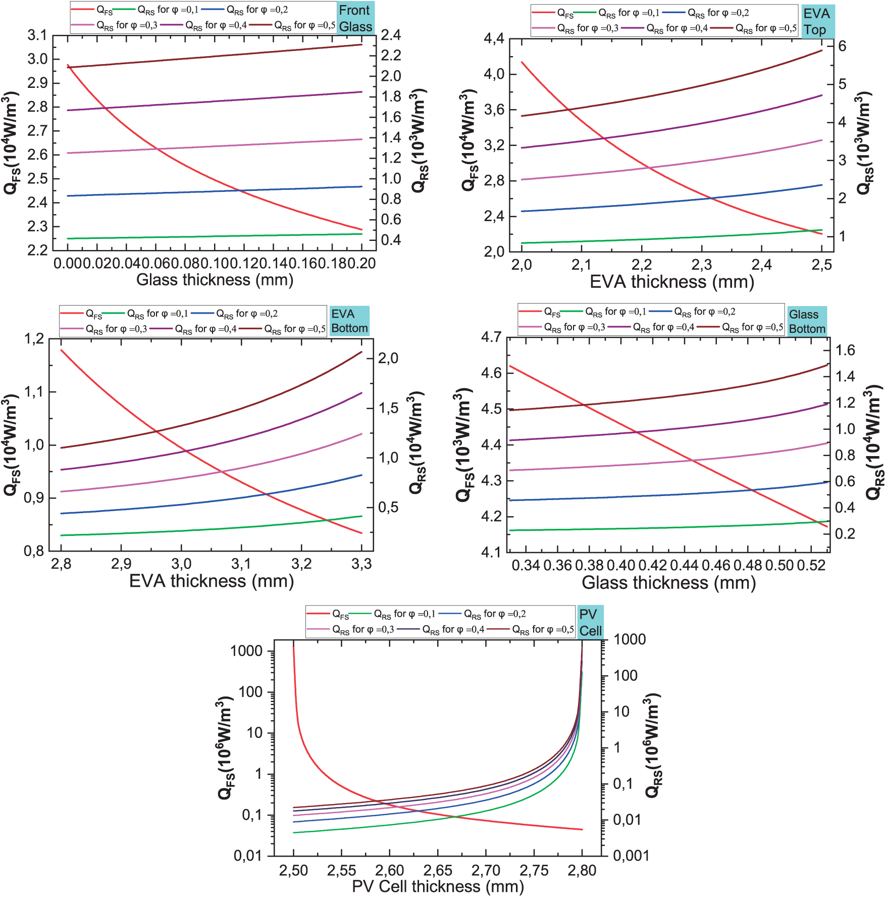
Figure 2: Internal heat sources generated by irradiance impinging on the Front Surface (FS) and reflected irradiance impacting Rear Surface (RS) for albedo values lying between 0 and 1, and for different layers: top Glass, top EVA, Si, bottom EVA, and bottom Glass
It is observed that the front glass layer exhibits higher heat generation due to direct exposure to incident radiation, while the bottom glass layer absorbs significantly less due to reduced transmitted irradiance. EVA layer also demonstrates a variation in heat generation; the top EVA layer generates more heat than the bottom EVA layer due to its proximity to direct irradiance and increased absorption of scattered light. In contrast, the bottom EVA layer receives lower irradiance because of absorption and reflection in the PV cell.
The PV cell exhibits the highest internal heat generation as it directly absorbs and converts solar energy into electrical power, with the remaining energy dissipated as heat. Additionally, it is noticeable that as the albedo coefficient increases, the internal heat generation on the rear side also increases. This is attributed to enhanced reflection from the ground or surrounding surfaces, leading to greater rear-side irradiance and subsequently increased heat accumulation.
Furthermore, the heat generation pattern is significantly influenced by the conductivity and thickness of each layer, which govern heat dissipation and accumulation throughout the module.
To evaluate the performance of the 1-D finite difference approach integrating internal heating due to incoming and reflected irradiance, various validation tests corresponding to different operating conditions have been conducted. Each test is explained in detail in the following sub-sections.
Standard Test Conditions (STC) correspond to an irradiance of 1000 W/m2, a back-surface temperature of 25°C, and an AM1.5G air mass. These conditions usually serve as a benchmark for evaluating the thermal behaviour of PV modules.
The right-hand graph in Fig. 3 illustrates temperature evolution at different interfaces between two neighbouring materials of the bPV module over time. It is observed that interfaces on both sides of the Si layer maintain the highest temperature values, which is due to the high absorption coefficient of Si, while external layers maintain lower temperature values. Additionally, temperature is seen to stabilize rapidly within the first minute, which indicates that the bPV module reaches thermodynamic equilibrium. Rapid stabilization is favoured by thermal diffusion, where heat is gradually spread through conduction across layers until equilibrium is reached, with convective and radiative losses balancing the system. The observed trends align well with expected thermal behaviours, where the temperature gradient is primarily governed by the thermal conductivity.
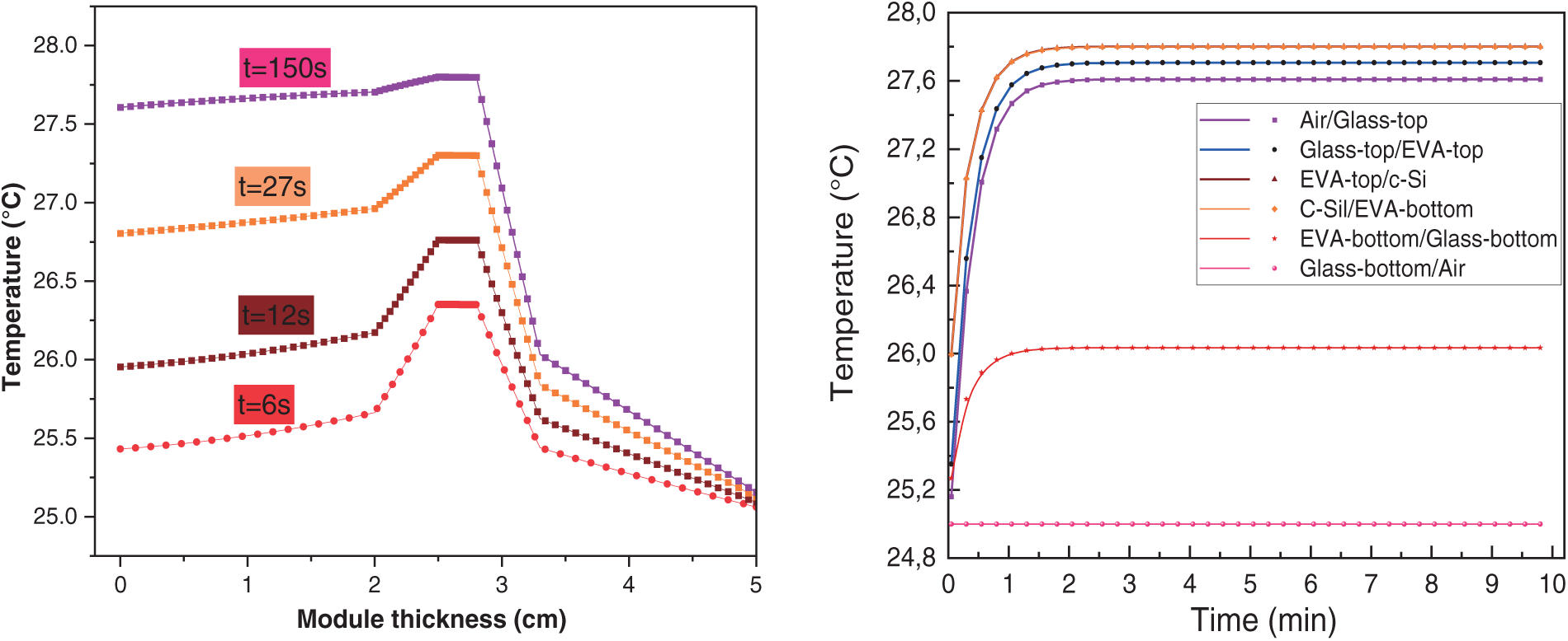
Figure 3: Temperature profiles at different times after application of irradiance (left) and evolution of temperature at different junctions between neighboring materials vs. time under STC conditions
The left-hand graph in Fig. 3 illustrates the temperature profile through a multi-layered structure at different instants following application of irradiance. Initially, temperature distribution exhibits a rapid increase due to absorption of solar radiation, followed by a gradual stabilization as heat diffusion through the layers becomes predominant. The thermal response at various times following ignition (6, 12, 27, 150 s) highlights the evolution of heat transfers due to conduction, convection, and radiation, confirming the capability of the FD approach to capture accurately transient thermal phenomena.
Bifacial standard test conditions (BSTC) are characterized by a rear irradiance of 135 W/m2, which corresponds to a 1-m ground clearance for a bPV module, consistent with the environmental specifications outlined in IEC 60904-3 [23,24].
The right side of Fig. 4 illustrates temperature evolution at different interfaces of a bifacial PV module under BSTC. The key difference between STC and BSTC is the additional irradiance received by the rear side, which leads to an overall increase in the module’s temperature, particularly affecting the rear interfaces. As previously discussed, heat conduction through the layers plays a crucial role in distributing thermal energy. However, in this case, bidirectional exposure results in a more uniform temperature gradient across the bPV module. On the other hand, lhs graph of Fig. 4 illustrates temperature distribution across the module at different times after application of irradiance under BSTC conditions. Initially, the temperature rise is concentrated near the front surface. As time progresses, heat gradually propagates through the layers, increasing temperature across the module. By t = 150 s, the system reaches a near-steady state, with a more pronounced temperature gradient. The results highlight the thermal response of the module, where heat conduction plays a key role in distributing energy across its thickness.
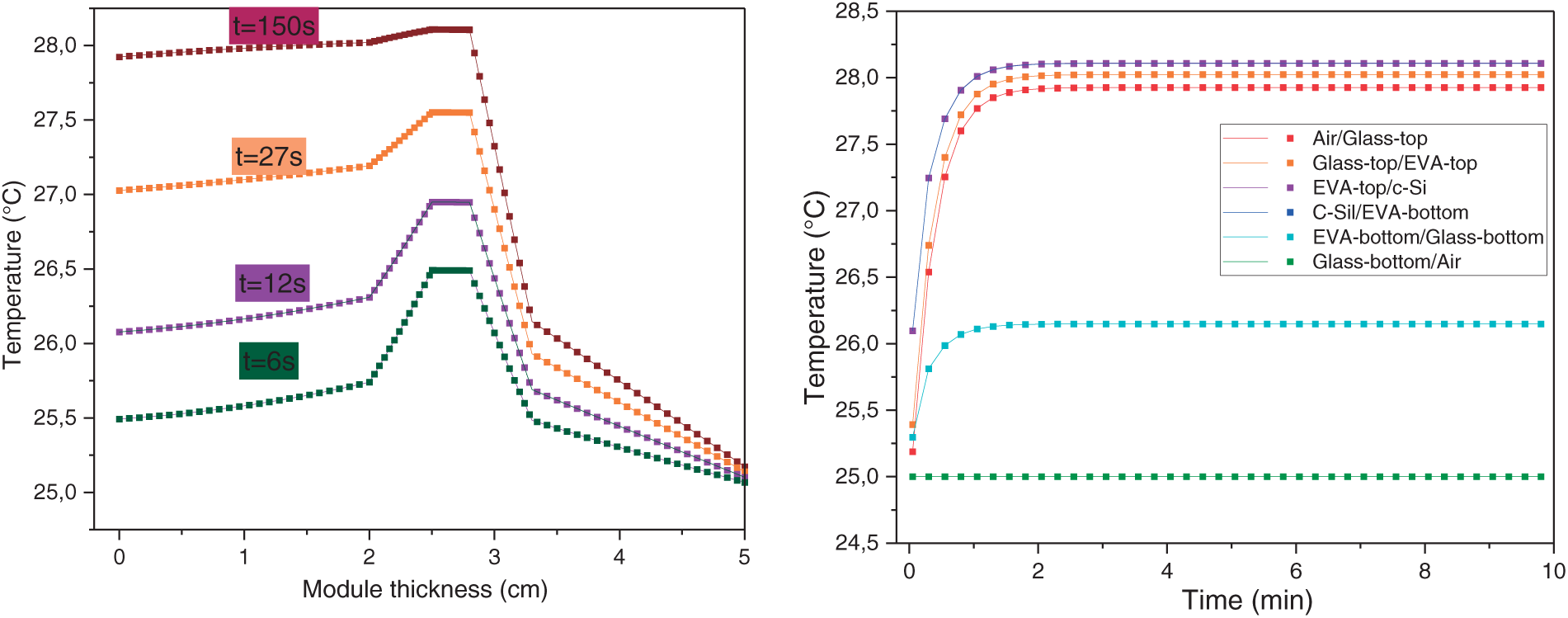
Figure 4: Temperature profiles at different times after application of irradiance (left) and evolution of temperature at different junctions between neighboring materials vs. time under BSTC conditions
Nominal Operating Cell Temperature (NOCT) corresponds to the following conditions: an incident irradiance of 800 W/m2, an ambient temperature of 20°C, a wind speed of 1 m/s, and a PV module mounted at a 45° tilt angle with open circuit.
Fig. 5 presents temperature evolution over time at different interfaces between neighbouring materials in the bPV module. The PV cell layer exhibits the highest temperature, while the front glass remains cooler than the back surface. This is attributed to the fact that the front glass is further away from the active layer and its a higher thermal conductivity, which enhances heat dissipation compared to the back sheet material. The temperature profile stabilizes quickly, indicating efficient heat transfer within the layers. The graphs (a), (b) and (c) of Fig. 6 illustrate the temperature profile through a multi-layered structure at different instants: 10 s (Fig. 6a), 35 s (Fig. 6b), and 60 s (Fig. 6c). A rapid increase in temperature is observed initially, followed by a stabilization phase as thermal equilibrium is reached. The PV cell layer (c-Si) consistently maintains the highest temperature, confirming its role as the primary heat-absorbing layer. In addition, the temperature difference between the front and back surfaces indicates a variation in heat dissipation.
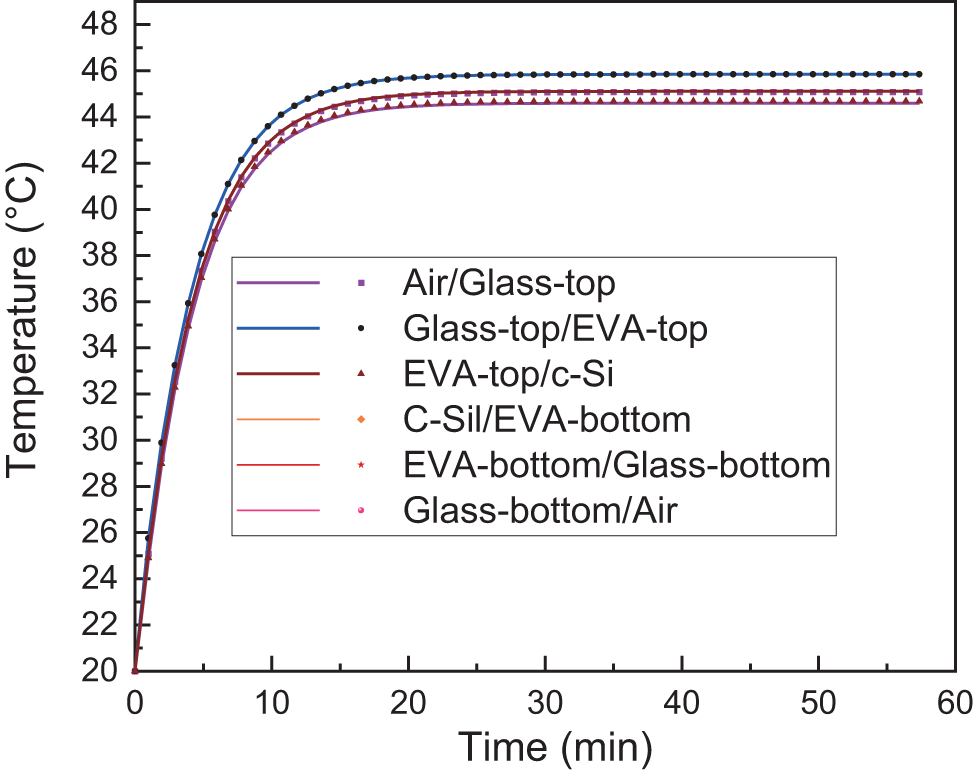
Figure 5: Evolution of the temperature of the module interface under NOCT conditions
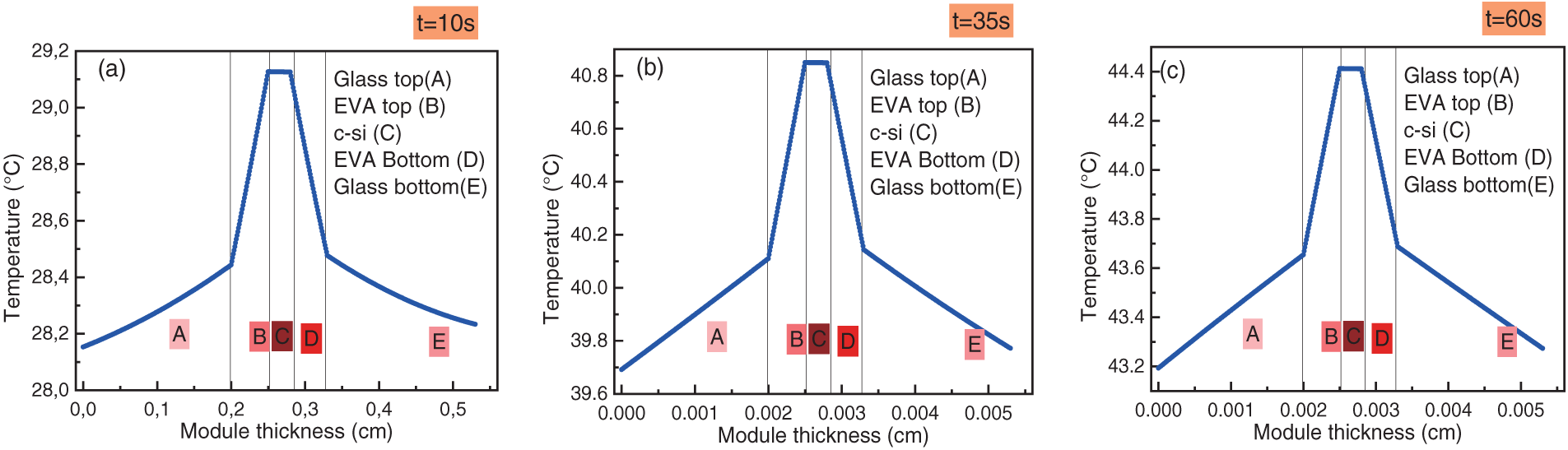
Figure 6: The temperature profiles throughout the multilayered structure within a bPV module at different times under NOCT
The maximum cell temperature observed in the simulation reached approximately 45°C, demonstrating strong consistency with the stabilized NOCT value reported in PV module datasheets.
These results provide insight into the thermal behaviour of the bPV module under NOCT conditions, validating the model’s ability to capture transient and steady-state temperature distributions.
Bifacial Nominal Operating Cell Temperature (BNOCT) is evaluated under the conditions, including an incident irradiance of 800 W/m2 on the front side, an ambient temperature of 20°C, a wind speed of 1 m/s, and additional rear-side irradiance determined by the albedo coefficient (φ).
Fig. 7 presents temperature profiles within the multilayered structure of a bifacial PV module for various albedo coefficients φ. As the albedo coefficient increases, the active layer temperature of the bPV module rises, indicating a significant impact of rear-side irradiance on the thermal behavior of the bPV module. The front glass layer remains cooler compared to the back surface, as heat is dissipated more effectively through its higher thermal conductivity.
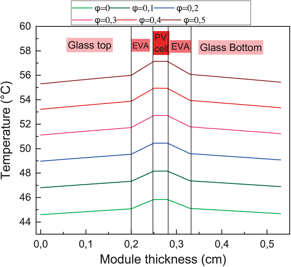
Figure 7: Temperature profiles within the multilayered structure of a bPV module for various albedo coefficients
These results highlight the influence of the environment on the thermal response of bifacial PV modules, emphasizing the necessity of considering rear-side contributions in thermal modeling and performance evaluation.
3.6 Impact of Albedo Coefficient on Power Output and Temperature Profiles of the bPV Module
Fig. 8 depicts the temperature profiles across the multilayered structure of a bPV module under different albedo coefficients, revealing their impact on the module’s thermal behavior and power output. As the albedo coefficient increases, more sunlight is reflected onto the rear side of the module, leading to a rise in equivalent irradiance. This boosts the power generation potential but also raises the module’s temperature.
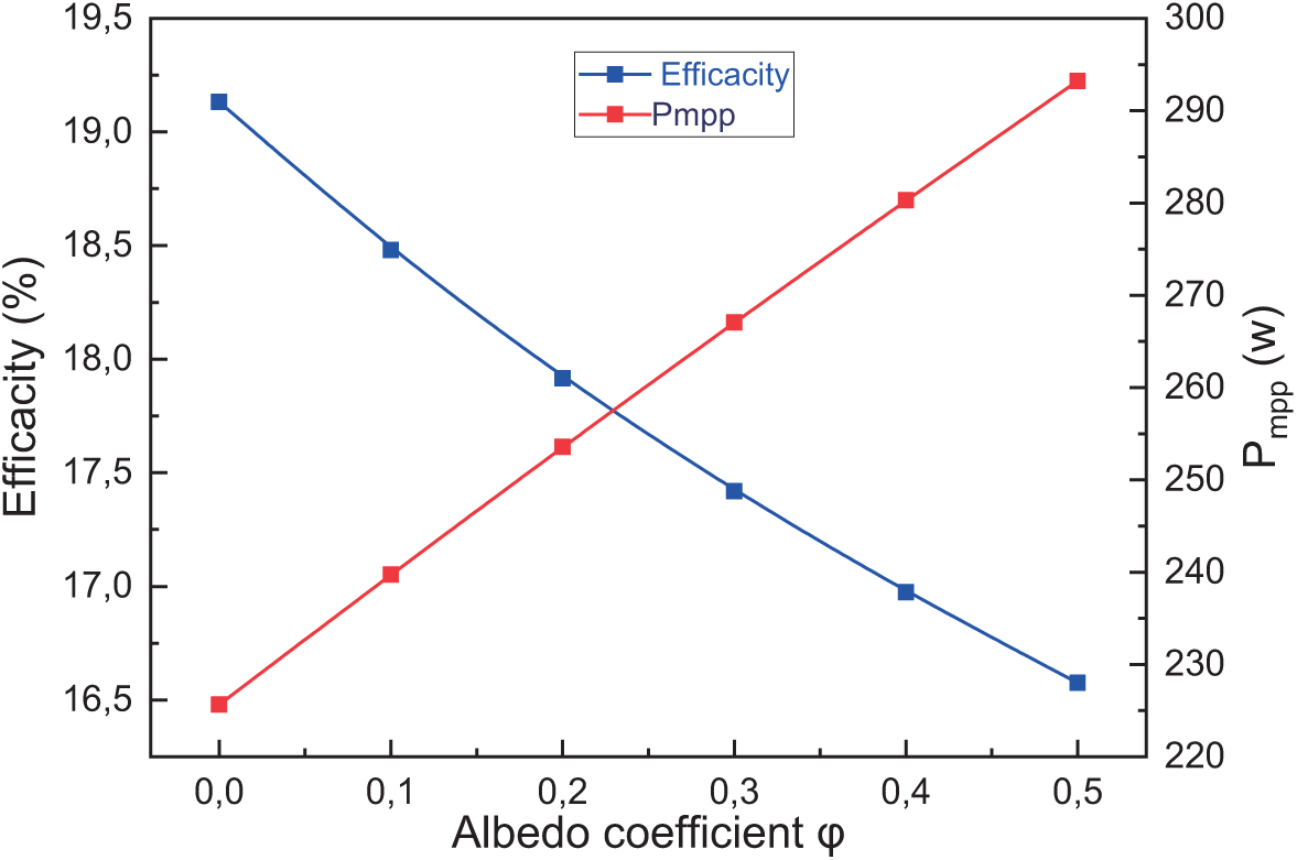
Figure 8: The bPV module power output at MPP and temperature profiles within the multilayered structure of a bPV module for various albedo coefficients as a function of albedo coefficients φ
The results show that the temperature of the bPV module increases with higher albedo values due to enhanced rear-side irradiance. While it is well established that elevated temperatures tend to reduce the electrical efficiency of PV cells, the overall power output of the module still increases. This is attributed to the additional energy received from ground-reflected light, which compensates for the thermal losses. For example, as the albedo coefficient increases from 0 to 0.5, the module’s electrical efficiency decreases from approximately 19.1% to 16.5%, while the maximum power output simultaneously increases from about 225 to 295 W. Therefore, despite the slight decline in efficiency, higher albedo levels result in a net gain in power output, demonstrating the beneficial impact of albedo on bifacial PV performance.
While higher temperatures negatively impact the electrical efficiency of PV modules primarily by reducing open-circuit voltage and fill factor, the overall power output continues to increase with rising albedo. This is because the additional irradiance reflected onto the rear side of the module more than compensates for the efficiency loss. These results highlight the complex trade-off between thermal losses and optical gains in bifacial systems. Therefore, optimizing thermal management becomes important not to prevent power loss, but to further improve module longevity and performance stability while still benefiting from albedo-enhanced irradiance.
This study presents a detailed thermal analysis of multilayer bifacial photovoltaic (bPV) modules under spectral solar illumination. A one-dimensional finite difference model was developed that uniquely integrates wavelength-dependent internal heat generation across each material layer, rather than assuming a uniform or constant heat source. This fine-level spectral treatment offers deeper insight into how light is absorbed and converted to heat within the multilayer structure, enhancing the physical accuracy of the thermal simulation.
The model successfully reproduces temperature profiles under various standard conditions (STC, BSTC, NOCT, and BNOCT), and demonstrates the significant role of albedo in influencing rear-side irradiance, thermal response, and power output. These results emphasize the importance of both material-level optical design and environmental ground conditions in optimizing bPV system performance.
Despite certain limitations, the modeling approach adopted in this study remains practical and appropriate for the objectives pursued. Heat transfer was modeled in one dimension, assuming homogeneity along the module surface. While this may not fully capture local effects such as shading or dust accumulation, it offers a computationally efficient way to study vertical heat transfer and internal spectral absorption. Although more detailed three-dimensional models have been developed in other studies to account for lateral thermal gradients and localized phenomena, the 1D approach remains a widely accepted first step, especially in early-stage thermal analysis. In addition, thermal and optical properties were considered temperature-invariant. This simplification is reasonable for the operating range examined, although it may introduce some limitations when extending the model to more extreme conditions.
The model serves as a valuable tool for early-stage design and optimization of bifacial PV systems, particularly in high-albedo environments. Future work will focus on extending the model to two or three dimensions, incorporating temperature-dependent material properties, and validating results through experimental techniques such as infrared thermography and in-situ sensor measurements. These enhancements will further improve the model’s predictive power and real-world applicability.
Acknowledgement: The authors gratefully acknowledge the support of Chouaïb Doukkali University for this work.
Funding Statement: The authors received no specific funding for this study.
Author Contributions: Khadija Ibaararen: conceptualization, methodology, software, writing, original draft, review and editing. Mhammed Zaimi: conceptualization, methodology, software, writing, original draft, review and editing. Khadija El Ainaoui: methodology, software, writing, original draft, review and editing. El Mahdi Assaid: methodology, software, writing, original draft, review and editing, supervision. All authors reviewed the results and approved the final version of the manuscript.
Availability of Data and Materials: Due to the nature of this research, participants did not consent to the public sharing of their data; as a result, the supporting data are not available.
Ethics Approval: Not applicable.
Conflicts of Interest: The authors declare no conflicts of interest to report regarding the present study.
Abbreviations
| bPV | Bifacial photovoltaic |
| FD | Finite Difference |
| STC | Standard Test Conditions |
| BSTC | Bifacial Standard Test Conditions |
| NOCT | Normal Operating Cell Temperature |
| BNOCT | Bifacial Normal Operating Cell Temperature |
| EVA | Ethylene-Vinyl Acetate |
| MPP | Maximum Power Point |
| AM1.5G | Air Mass 1.5 Global spectrum |
| Symbols | |
| Time | |
| Density | |
| Specific heat capacity | |
| Temperature | |
| Thermal conductivity | |
| Internal heat generation | |
| Spectral absorption coefficient | |
| Thickness of layer i | |
| Global spectral solar irradiance impinging front side | |
| Global spectral solar irradiance impinging rear side | |
| Spectral transmittance | |
| bPV efficiency | |
| Front surface area | |
| Total heat transfer coefficient | |
| Natural heat transfer coefficient | |
| Forced heat transfer coefficient | |
| Air thermal conductivity | |
| Module length | |
| Nusselt number for free convection | |
| Nusselt number for forced convection | |
| Rayleigh number | |
| Grashof number | |
| Gravitational acceleration | |
| Air kinematic viscosity | |
| Air volumetric thermal expansion coefficient | |
| Prandtl number | |
| Air specific heat capacity | |
| Air dynamic viscosity | |
| Reynolds number | |
| Wind speed | |
| Radiative heat transfer coefficient for Sky (Ground) | |
| Stefan-Boltzmann constant | |
| Surface emissivity of the bPV module | |
| Ground temperature | |
| Ambient temperature | |
| Sky temperature | |
| View factors of radiative transfer between the front glass or the back glass | |
| bPV module tilt angle | |
| The distance separating two consecutive grid points in layer m | |
| Lapse of time between two consecutive grid points in time | |
| MPP under standard test conditions | |
| Equivalent irradiance received by the bPV module | |
| Reference irradiance under STC | |
| Temperature coefficient of MMP | |
| Module temperature and STC | |
| Reference temperature | |
| Bifaciality factor | |
| Front-side in-plane irradiance | |
| Rear-side in-plane irradiance | |
| Albedo coefficient | |
| Total incident power | |
References
1. El Ainaoui K, Zaimi M, Flouchi I, Elhamaoui S, El mrabet Y, Ibaararen K, et al. Novel optimized models to enhance performance forecasting of grid-connected PERC PV string operating under semi-arid climate conditions. Sol Energy. 2024;282:112976. doi:10.1016/j.solener.2024.112976. [Google Scholar] [CrossRef]
2. d’Alessandro V, Daliento S, Dhimish M, Guerriero P. Albedo reflection modeling in bifacial photovoltaic modules. Solar. 2024;4(4):660–73. doi:10.3390/solar4040031. [Google Scholar] [CrossRef]
3. Gu W, Li S, Liu X, Chen Z, Zhang X, Ma T. Experimental investigation of the bifacial photovoltaic module under real conditions. Renew Energy. 2021;173(8):1111–22. doi:10.1016/j.renene.2020.12.024. [Google Scholar] [CrossRef]
4. Zhang Z, Wu M, Lu Y, Xu C, Wang L, Hu Y, et al. The mathematical and experimental analysis on the steady-state operating temperature of bifacial photovoltaic modules. Renew Energy. 2020;155(1):658–68. doi:10.1016/j.renene.2020.03.121. [Google Scholar] [CrossRef]
5. Aly SP, Barth N, Figgis BW, Ahzi S. A fully transient novel thermal model for in-field photovoltaic modules using developed explicit and implicit finite difference schemes. J Comput Sci. 2018;27:357–69. doi:10.1016/j.jocs.2017.12.013. [Google Scholar] [CrossRef]
6. Aly SP, Ahzi S, Barth N, Abdallah A. Using energy balance method to study the thermal behavior of PV panels under time-varying field conditions. Energy Convers Manag. 2018;175:246–62. doi:10.1016/j.enconman.2018.09.007. [Google Scholar] [CrossRef]
7. Gu W, Ma T, Li M, Shen L, Zhang Y. A coupled optical-electrical-thermal model of the bifacial photovoltaic module. Appl Energy. 2020;258:114075. doi:10.1016/j.apenergy.2019.114075. [Google Scholar] [CrossRef]
8. Hanifi H, Regondi S, Jaeckel B, Schneider J. Determination of electrical characteristics and temperature of PV modules by means of a coupled electrical-thermal model. J Renew Sustain Energy. 2020;12(2):023501. doi:10.1063/5.0001599. [Google Scholar] [CrossRef]
9. Sánchez Barroso JC, Barth N, Correia JPM, Ahzi S, Khaleel MA. A computational analysis of coupled thermal and electrical behavior of PV panels. Sol Energy Mater Sol Cells. 2016;148:73–86. doi:10.1016/j.solmat.2015.09.004. [Google Scholar] [CrossRef]
10. Rao Golive Y, Kottantharayil A, Shiradkar N. Improving the accuracy of temperature coefficient measurement of a PV module by accounting for the transient temperature difference between cell and backsheet. Sol Energy. 2022;237(2):203–12. doi:10.1016/j.solener.2022.03.049. [Google Scholar] [CrossRef]
11. Woo M, Sim M, Sohn JW, Choi S, Pyun D, Choi D, et al. Impact of TiO2 on performance and thermal characteristics of bifacial solar modules: a computational and experimental approach. Mater Sci Semicond Process. 2025;197(3):109707. doi:10.1016/j.mssp.2025.109707. [Google Scholar] [CrossRef]
12. Abo-Zahhad EM, Hares E, Esmail MFC, Salim MH. Simplified modeling of polycrystalline solar module performance in a semi-arid region. Case Stud Therm Eng. 2024;60(1):104762. doi:10.1016/j.csite.2024.104762. [Google Scholar] [CrossRef]
13. Ibaararen K, Zaimi M, Ainaoui KE, Assaid EM. Determination of temperature profile inside a PV module operating under specific conditions using a model coupling internal heating to optical absorption. Procedia Comput Sci. 2024;236:17–24. doi:10.1016/j.procs.2024.04.335. [Google Scholar] [CrossRef]
14. Gu W, Ma T, Ahmed S, Zhang Y, Peng J. A comprehensive review and outlook of bifacial photovoltaic (bPV) technology. Energy Convers Manag. 2020;223:113283. doi:10.1016/j.enconman.2020.113283. [Google Scholar] [CrossRef]
15. Aalloul R, Elaissaoui A, Harkani A, Adhiri R, Benlattar M. A simulation and modeling approach of coupled thermal and electrical behavior of PV panels using the artificial hummingbird algorithm and two-dimensional finite difference-based model. Heliyon. 2024;10(6):e27244. doi:10.1016/j.heliyon.2024.e27244. [Google Scholar] [PubMed] [CrossRef]
16. Bevilacqua P, Bruno R, Rollo A, Ferraro V. A novel thermal model for PV panels with back surface spray cooling. Energy. 2022;255:124401. doi:10.1016/j.energy.2022.124401. [Google Scholar] [CrossRef]
17. Cole RJ, Sturrock NS. The convective heat exchange at the external surface of buildings. Build Environ. 1977;12(4):207–14. doi:10.1016/0360-1323(77)90021-X. [Google Scholar] [CrossRef]
18. Armstrong S, Hurley WG. A thermal model for photovoltaic panels under varying atmospheric conditions. Appl Therm Eng. 2010;30(11–12):1488–95. doi:10.1016/j.applthermaleng.2010.03.012. [Google Scholar] [CrossRef]
19. Sparrow EM, Ramsey JW, Mass EA. Effect of finite width on heat transfer and fluid flow about an inclined rectangular plate. J Heat Transf. 1979;101(2):199–204. doi:10.1115/1.3450946. [Google Scholar] [CrossRef]
20. Ma T, Guo Z, Shen L, Liu X, Chen Z, Zhou Y, et al. Performance modelling of photovoltaic modules under actual operating conditions considering loss mechanism and energy distribution. Appl Energy. 2021;298:117205. doi:10.1016/j.apenergy.2021.117205. [Google Scholar] [CrossRef]
21. Skoplaki E, Palyvos JA. On the temperature dependence of photovoltaic module electrical performance: a review of efficiency/power correlations. Sol Energy. 2009;83(5):614–24. doi:10.1016/j.solener.2008.10.008. [Google Scholar] [CrossRef]
22. Mannino G, Tina GM, Jiménez-Castillo G, Cacciato M, Bizzarri F, Canino A. Nonlinear and multivariate regression models of current and voltage at maximum power point of bifacial photovoltaic strings. Sol Energy. 2024;269(4):112357. doi:10.1016/j.solener.2024.112357. [Google Scholar] [CrossRef]
23. Zhang X, Monokroussos C, Schweiger M, Heinze M. Power rating and qualification of bifacial PV modules [Internet]. [cited 2024 Aug 23]. Available from: https://www.pv-tech.org/wp-content/uploads/legacy-publication-pdfs/f8414dc87c-power-rating-and-qualification-of-bifacial-pv-modules.pdf. [Google Scholar]
24. IEC 60891. Photovoltaic devices—procedures for temperature and irradiance corrections to measured I-V characteristics [Internet]. [cited 2023 Jun 17]. Available from: https://webstore.iec.ch/preview/info_iec60891%7Bed3.0%7Db.pdf. [Google Scholar]
Cite This Article
 Copyright © 2025 The Author(s). Published by Tech Science Press.
This work is licensed under a Creative Commons Attribution 4.0 International License , which permits unrestricted use, distribution, and reproduction in any medium, provided the original work is properly cited.
 Downloads
 Citation Tools