
 Submit a Paper
 Propose a Special lssue
 Open Access
ARTICLE

A Non-Unit Protection Based on Propagation of Fault Traveling Wave for Transmission Line Connected to Wind Power Plant
Power System Security and Operation Key Laboratory of Sichuan Province, State Grid Sichuan Electric Power Research Institute, Chengdu, 610041, China
* Corresponding Author: Hao Wang. Email:
(This article belongs to the Special Issue: Integrated Technology Development and Application of Wind Power Systems)
Energy Engineering 2025, 122(9), 3737-3752. https://doi.org/10.32604/ee.2025.067938
Received 16 May 2025; Accepted 29 July 2025; Issue published 26 August 2025
 View Full Text
 Download PDF
Abstract
Currently, renewable energy has been broadly implemented across diverse sectors, particularly evidenced by its substantially higher integration levels in power systems. The large-scale integration of renewable energy resources introduces distinct fault characteristics into power grids, potentially rendering traditional line protection schemes inadequate for transmission lines interfacing with these sources. Therefore, it is imperative to study line protection methods unaffected by the integration of renewable energy resources. After analyzing the propagation process of the fault traveling wave along the transmission line, a non-unit protection based on traveling wave distance measurement is proposed. The core principle of the proposed method relies on measuring the temporal interval ΔT between detections of the first and second fault backward traveling waves at the measurement point. The Teager energy operator (TEO), which demonstrates advantages in highlighting step mutation characteristics, was employed to extract ΔT by processing the fault backward traveling wave signal detected at the measurement point. To evaluate the efficacy of the proposed protection method, various fault scenarios were simulated in the established PSCAD/EMTDC simulation system. Validation results confirm that the proposed non-unit protection can provide full-line protection coverage, enabling fast and reliable discrimination of internal and external faults with inherent immunity to renewable energy penetration.Keywords
The accelerated depletion of carbon-intensive resources, coupled with the escalating climate crisis, has catalyzed exponential expansion in harvesting renewable energy resources, particularly within modernized power systems [1–4]. However, the grid-scale proliferation of renewable generation—predominantly inverter-interfaced wind and solar resources—introduces novel fault signatures, undermining the efficacy of conventional line protection schemes designed for synchronous machine-dominated systems [5–9]. For example, due to the weak feed characteristic of the current, the sensitivity of the current differential protection is reduced, and the ability of the power frequency quantity distance protection to resist transient resistance is decreased. Affected by the control strategies of the renewable energy sources, their equivalent impedance changes, leading to a decrease in the reliability of the directional elements based on the impedance of the backside system, and even misjudgments may occur. Therefore, it is necessary to study protection methods that can be applied to the transmission lines of renewable energy.
Currently, scholars have carried out studies on transmission line protection methods for power grids that accommodate the integration of renewable energy sources. These studies can be divided into two categories: one involves improved methods for traditional protections, and the other explores new principles for protections.
In terms of improving traditional protection methods, authors in [10] proposed a fault current classification method to enhance the calculation accuracy of measured impedance. But this method is still based on frequency-domain information. Its operation speed is constrained by frequency deviations and harmonic distortions in wind plant-connected transmission line fault currents, attributed to the transient response characteristics of power electronics. In [11], a new distance protection based on positive sequence voltage was introduced. However, this protection method is only applicable to phase-to-phase faults. In [12], a distance protection with an adaptive time delay based on frequency estimation was proposed. The method in [13] adapted the operating zone of distance protection based on the dynamic response of renewable energy sources, effectively mitigating both overreach and under-reach issues. Although these two methods advance conventional distance protection adaptability to renewable energy sources, they still exhibit drawbacks, including inadequate transient response characteristics and slow operation speed in complex fault situations. An adaptive distance protection is proposed in [14]. However, zone II of the proposed protection may fail to achieve coordination with zone I on the adjacent line. Authors in [15] proposed an improved current differential protection based on wideband quantities. Though the enhanced method performs well under different fault situations, it imposes special requirements on CT, which limits its practical application. In [16], an artificial neural network is applied to adaptively adjust the setting values of distance protection criteria based on different fault scenarios. However, considering that the artificial neural network requires a large amount of correct and reliable data for training, the practical usability of the method proposed in [16] needs further discussion. Authors in [17] propose a new solution method for differential equations of the R-L model to optimize the performance of time-domain distance protection. However, the method in [17] ignores the effects of the distributed capacitance of the line, resulting in limited performance of the proposed method in long transmission lines. Then, authors in [18] analyzed the error of the time-domain fault location method based on the R-L model and presented an improved scheme unaffected by distributed capacitance.
In terms of studies on new protection principles, authors in [19] introduced a localized protection scheme that utilizes current and voltage signals for precise fault detection. Nevertheless, voltage-dependent protection methods exhibit inherent drawbacks, including slow operating speed and reduced sensitivity to high-resistance faults. References [20,21] developed impedance-based differential protection schemes. These schemes, however, impose stringent synchronization requirements for data acquisition from both line terminals. Reference [22] utilized transient high-frequency impedance characteristics for fault detection, providing valuable insights for new energy transmission line protection. Authors in [23,24] employed current cosine similarity and bilateral waveform correlation analysis to develop pilot protection schemes. While demonstrating strong tolerance to fault resistance, these schemes necessitate stringent synchronization of dual-terminal measured data. Reference [25] introduced a pilot protection scheme utilizing the similarity and squared error of multi-band (10–200 Hz) components of currents from both ends of the line. However, the performance of the protection is potentially limited by inverter control interactions within this frequency range. In [26], a pilot protection based on the sequence current ratio was introduced. The proposed method only utilizes the amplitude feature, thereby requiring lower time synchronization. References [27,28] introduced an innovative inter-harmonic-based differential protection method, where inverters are controlled to inject specific inter-harmonic components into the power system. Fault discrimination is achieved by analyzing the differential characteristics of harmonic distributions across transmission line terminals.
Based on the preceding analysis, a summary is presented in Table 1. As shown in Table 1, despite significant research efforts devoted to various protection schemes that demonstrate effectiveness, they still exhibit limitations.
In this paper, a transmission line protection unaffected by renewable energy sources is proposed, and simulation tests based on PSCAD have been done to validate the performance of the proposed protection.
The remainder of the paper is organized as follows: the fault traveling wave propagation characteristics are introduced in Section 2. Section 3 introduces the proposed protection, including its fundamental principle, criteria, and the flow chart. Section 4 shows different simulation tests. Section 5 is the conclusion part.
2 Traveling Wave Propagation Characteristics
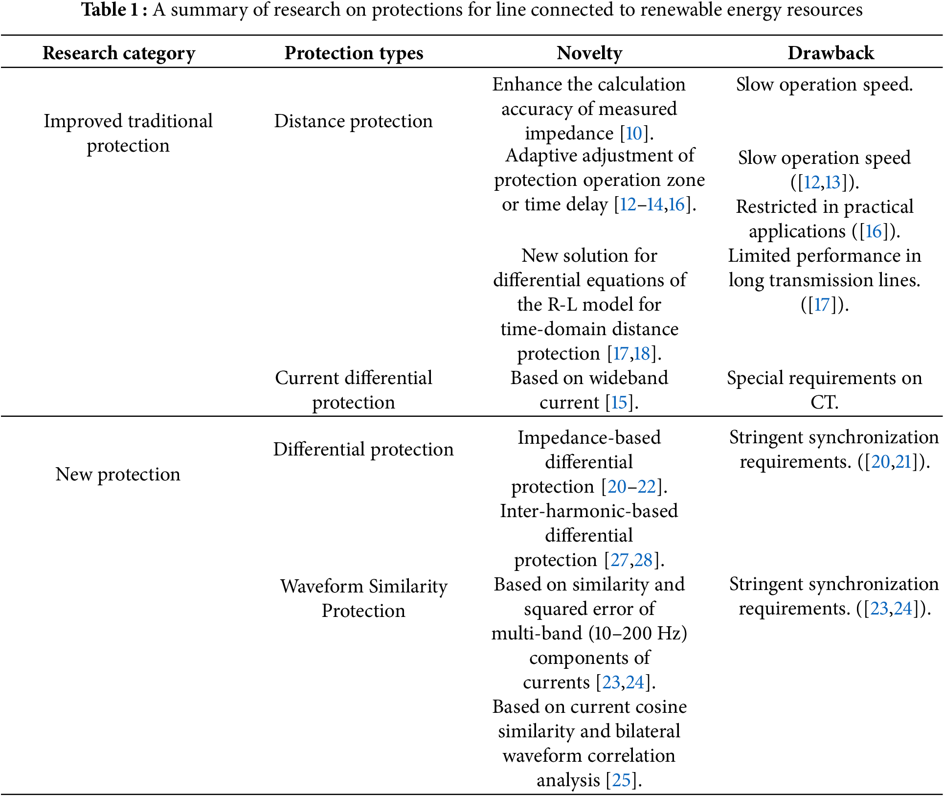
Based on the two-terminal system shown in Fig. 1, the positive direction is designated as the orientation from the bus toward the line. For point M, the blue arrow denotes the forward traveling wave, propagating in the positive direction; the red arrow indicates the backward-propagating wave, whose propagation direction is opposite to the positive direction.
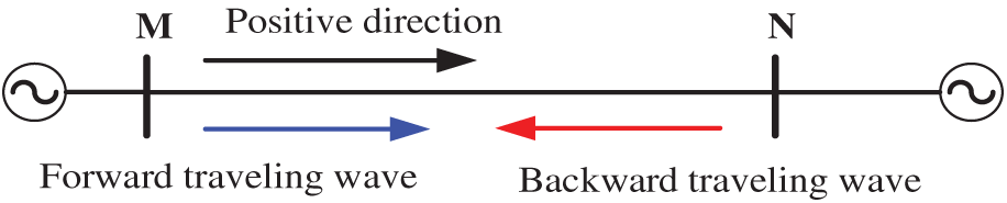
Figure 1: The two-terminal system
Upon the inception of an internal fault, the fault traveling wave emanates from the fault point and propagates bidirectionally toward terminals M and N. When the fault traveling wave arrives at point M, the fault backward traveling wave is detected at point M for the first time, while the surge impedance discontinuity at this junction simultaneously induces wave refraction and reflection phenomena. Then, the reflected wave continues to propagate backward to the fault point. Upon reaching the fault point, refraction and reflection occur again due to the surge impedance disparity at this discontinuity interface. And the refracted traveling wave continues to propagate to point N, and the reflected traveling wave propagates backward to point M. For point N, there is a similar propagation process.
As mentioned above, the initial detection of the fault backward traveling wave at point M occurs at the first arrival of the fault traveling wave generated at the fault point. However, the second detection bifurcates into two distinct scenarios.
In the first scenario, as shown in Fig. 2, the fault location is on segment ON, and point O is the midpoint of transmission line MN. From Fig. 2, the fault backward wave detected for the second time at point M is the arrival of
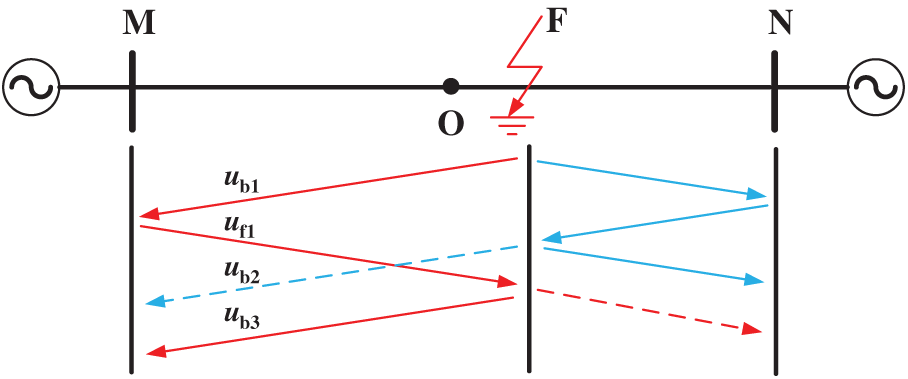
Figure 2: The propagation process of the fault traveling wave in the first internal fault scenario
In the second scenario, as shown in Fig. 3, the fault location is on segment MO, and point O is the midpoint of transmission line MN. From Fig. 3, the second detection of the fault backward traveling wave at point M is the arrival
Figure 3: The propagation process of the fault traveling wave in the second internal fault scenario
For the external faults, the fault situations can be divided into two situations.
Fig. 4 shows one of the external fault situations. When the fault occurs at the position shown in Fig. 4, the fault traveling wave generated at the fault point is refracted at point N, and the refracted traveling wave propagates from point N to point M. When the refracted traveling wave reaches point M, the fault backward traveling wave
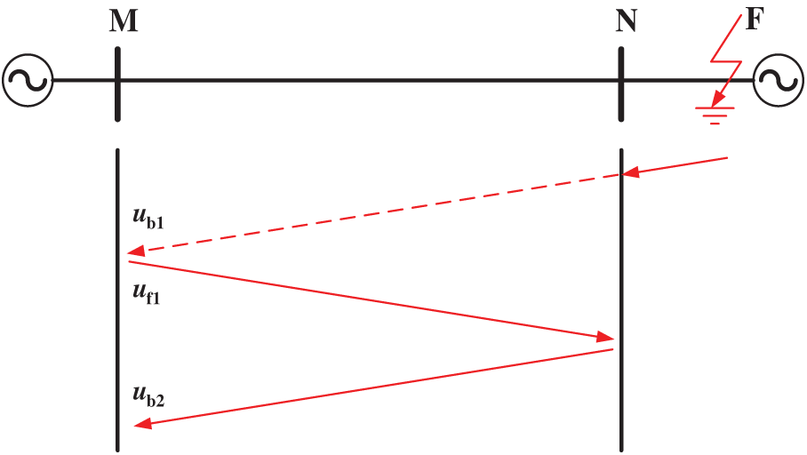
Figure 4: The propagation of the fault traveling wave under an external fault
Fig. 5 shows another external fault situation. The fault position is on the dorsal side of point M. When the fault occurs, the fault traveling wave is refracted at point M, and the refracted traveling wave
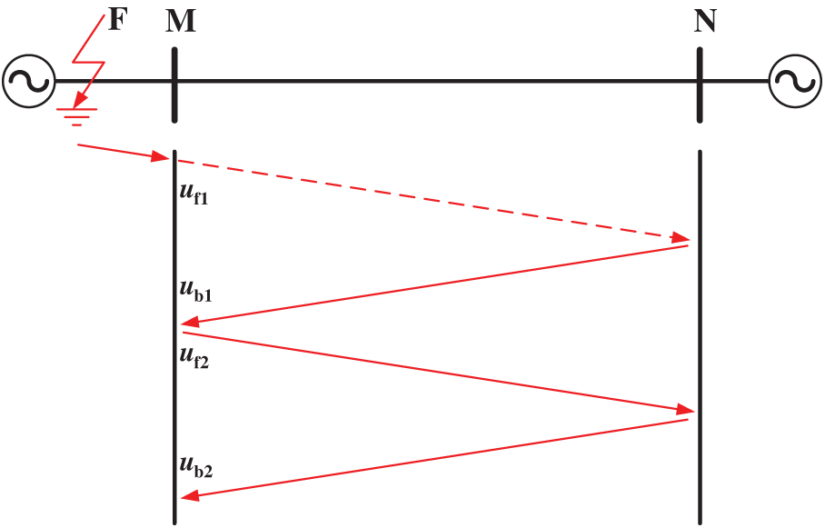
Figure 5: The propagation of the fault traveling wave under an external fault
From the analysis above, the temporal interval between the initial and secondary arrivals of the fault backward traveling wave can be used to determine whether the fault occurred on the protected transmission line.
Suppose the propagation speed of the fault traveling wave is
For the first case of internal fault, based on Fig. 2, the relationship of
Based on Fig. 2, the relationship of
Based on Figs. 3 and 4, the relationship of
From (1) and (2), for the internal faults, the calculation result of
3 The Transmission Line Protection Method
3.1 Obtainment of Fault Backward Traveling Wave
The three-phase lines are coupled with each other. To avoid such effects, the three-phase voltage and current need to be decoupled. The phase-mode transformation is employed to deal with the three-phase current and voltage. Taking voltage as an example, the transformation of voltage is:
In (4), the subscripts A, B, and C denote the three-phase quantities, the subscripts 0, α, and β denote the zero-mode component, α-mode component, and β-mode component, respectively.
Based on (4), the α-mode components used to obtain the fault backward traveling wave are calculated by:
where,
After obtaining
where,
Based on the transmission line whose structure is shown in Fig. 6, the fault backward traveling wave during an internal fault is calculated here. The α-mode surge impedance of the transmission line required for the calculation process varies with frequency, as shown in Fig. 7. As Fig. 7 illustrates, the α-mode surge impedance does not vary much at different frequencies. Therefore, the surge impedance used in (7) can be set to 350 Ω.
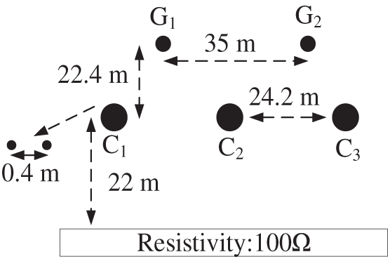
Figure 6: The structure of the transmission line
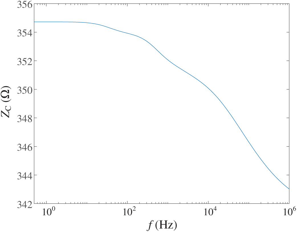
Figure 7: The surge impedance of the transmission line under different frequencies
The calculation result is shown in Fig. 8. Before the fault occurs, there is no fault component, and consequently no fault backward traveling wave, corresponding to the waveform near zero in the first half of Fig. 8. After the fault occurs, a fault backward traveling wave is generated, corresponding to the waveform in the latter half of Fig. 8. From Fig. 8, the fault backward traveling wave exhibits multiple step mutations (as marked by the red dashed rectangles in the figure) after the fault occurs. And these mutations are caused by the fault backward traveling waves reaching the measurement point.
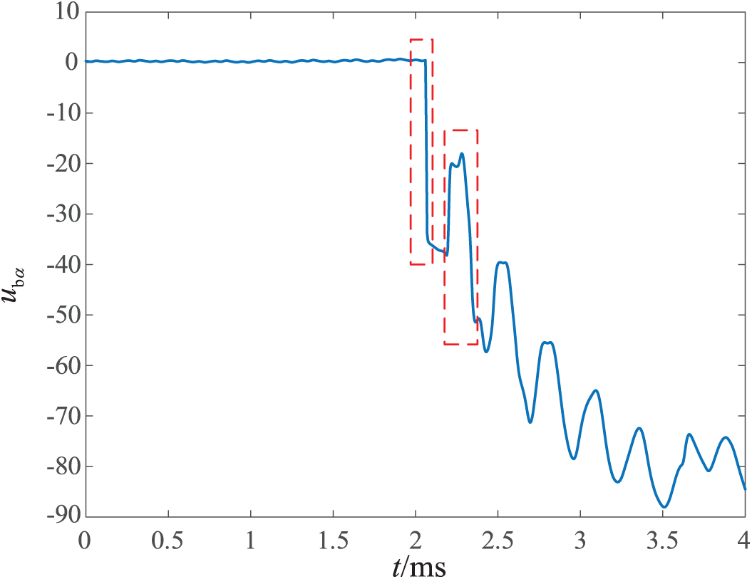
Figure 8: The calculated fault backward traveling wave
Since each step mutation in the waveform represents the arrival of the fault backward traveling wave at the measurement point, quantitative identification of these step mutations enables determination of
3.2 Identification of Step Mutations
As demonstrated in Section 3.1, finding a method to accurately quantify and identify step mutations of the fault backward traveling wave is essential for reliably distinguishing between internal faults and external faults. The Teager Energy Operator (TEO) is employed to deal with the fault backward traveling wave to find step mutations.
TEO is a nonlinear signal processing operator that quantifies the instantaneous energy. Its expression can be written as:
where,
Take a cosine signal as an example to characterize the properties of TEO. Define
It can be seen from (8) that TEO considers both the amplitude and frequency of a signal when tracking the energy changes of the signal. Compared to conventional instantaneous energy signal processing methods that solely consider amplitude information, TEO possesses an inherent advantage in describing the characteristics of step mutations in a signal more clearly, as step mutations exhibit not only drastic amplitude variations but also contain abundant high-frequency components.
Using TEO, the fault backward traveling wave shown in Fig. 8 is processed here. And the processing result is presented in Fig. 9. In Fig. 9, the blue solid line represents the processed result of the fault backward traveling wave in Fig. 8, while the green dashed line is the waveform shown in Fig. 8. As evidenced in Fig. 9, the TEO processing has significantly enhanced the characterization of the step mutations in the fault backward traveling wave shown in Fig. 8. This improvement is manifested through more distinct waveform spikes in Fig. 9 (as highlighted by the red dashed rectangles).
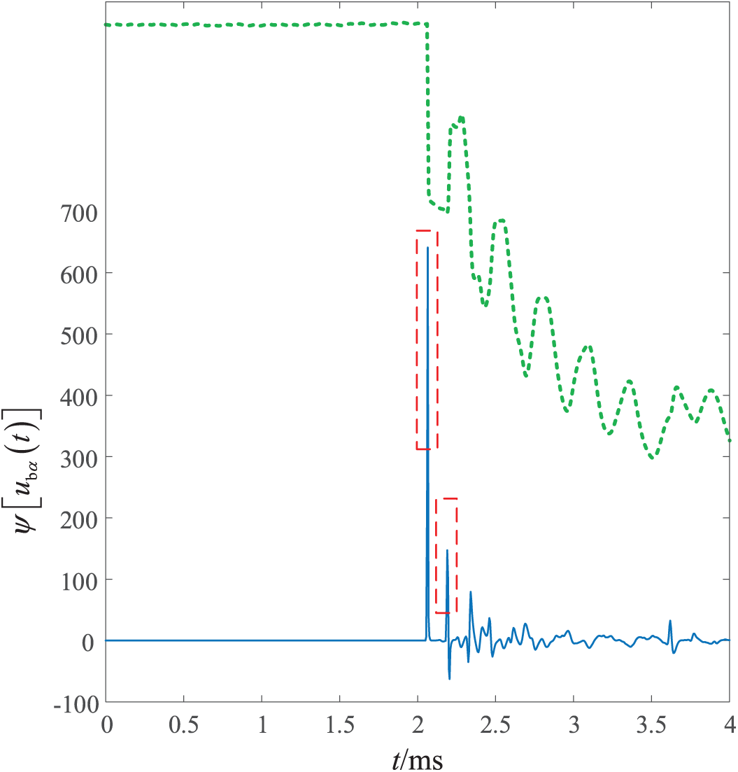
Figure 9: The results of processing the fault backward traveling wave
3.3 The Criterion and Flow Chart
Based on the introduction of Section 3.1, define
where,
where
Substituting (9) into (6) gives:
As the sampling signal is discrete, the discrete TEO is needed. For a discrete signal
Based on (11) and (12), calculate
After obtaining
where,
The flow chart of the protection is shown in Fig. 10. As illustrated in Fig. 10, when the start criterion is satisfied,
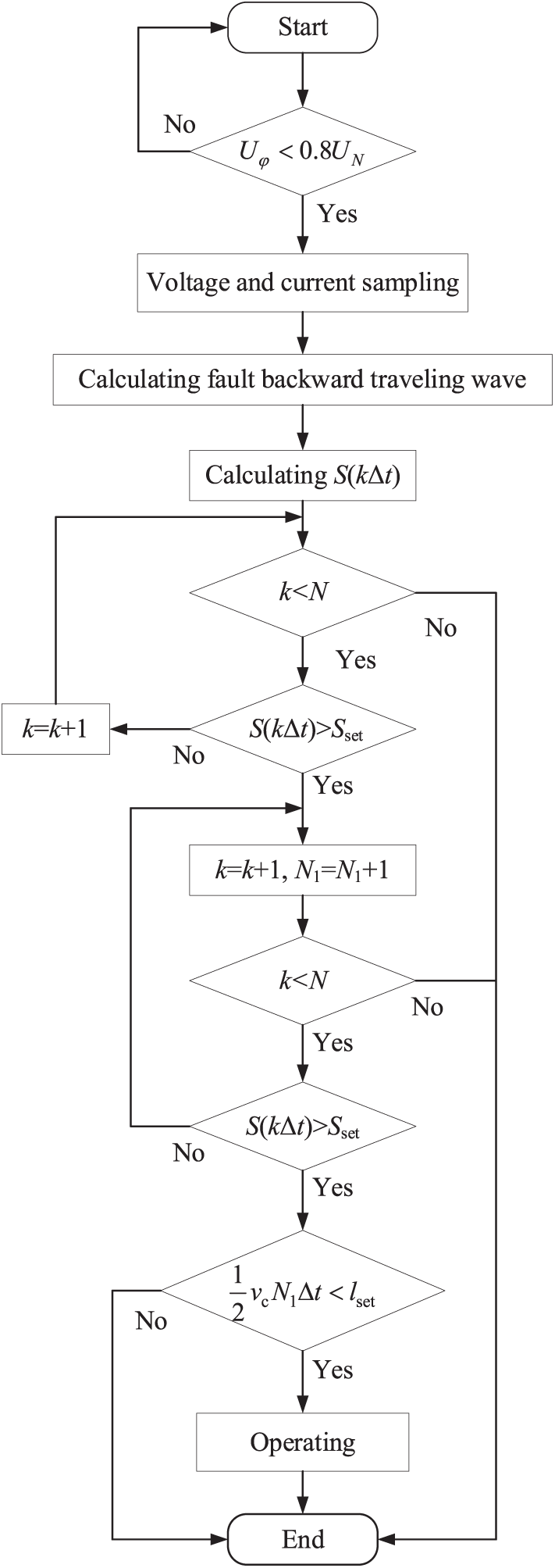
Figure 10: The flow chart
The performance evaluation of the proposed protection was conducted using a simulation system built in PSCAD/EMTDC, as shown in Fig. 11. In the figure, the conventional AC grid is connected to the left terminal of the transmission line, while the wind power plants are connected to the right terminal.
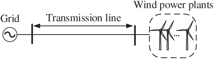
Figure 11: The structure of the simulation system
The speed of the α-mode traveling wave at different frequencies is shown in Fig. 12. As seen in Fig. 12, the speed of the α-mode traveling wave remains relatively constant across various frequencies. And the speed
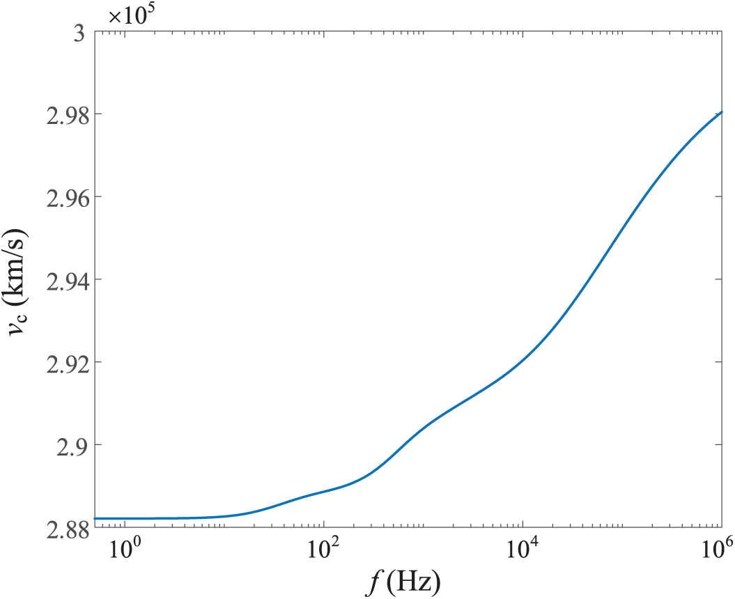
Figure 12: The speed of the α-mode traveling wave under different frequencies
4.1 Performance Evaluation under Different Fault Types
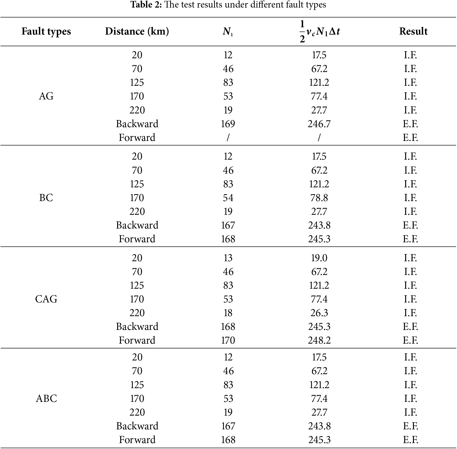
The performance of the proposed protection is validated through multi-type fault emulations within the simulation system. Table 2 shows the test results. Table entries “AG”, “BC”, “CAG”, and “ABC” denote single-phase grounding fault on phase A, phase-to-phase short-circuit fault on phase B and C, phase-to-phase short-circuit grounding fault on phase C and A, and three-phase short-circuit fault, respectively. “Distance” denotes the distance from the fault point to the bus of the wind power plant side, and the “Backward” and “Forward” represent two cases of external faults. “I.F.” and “E.F.” denote the determination results of the proposed protection, with “I.F.” indicating an internal fault and “E.F.” representing an external fault. As evidenced in Table 2, the proposed protection achieves reliable discrimination of diverse internal and external fault scenarios
4.2 Discussion about the Influence of Fault Time
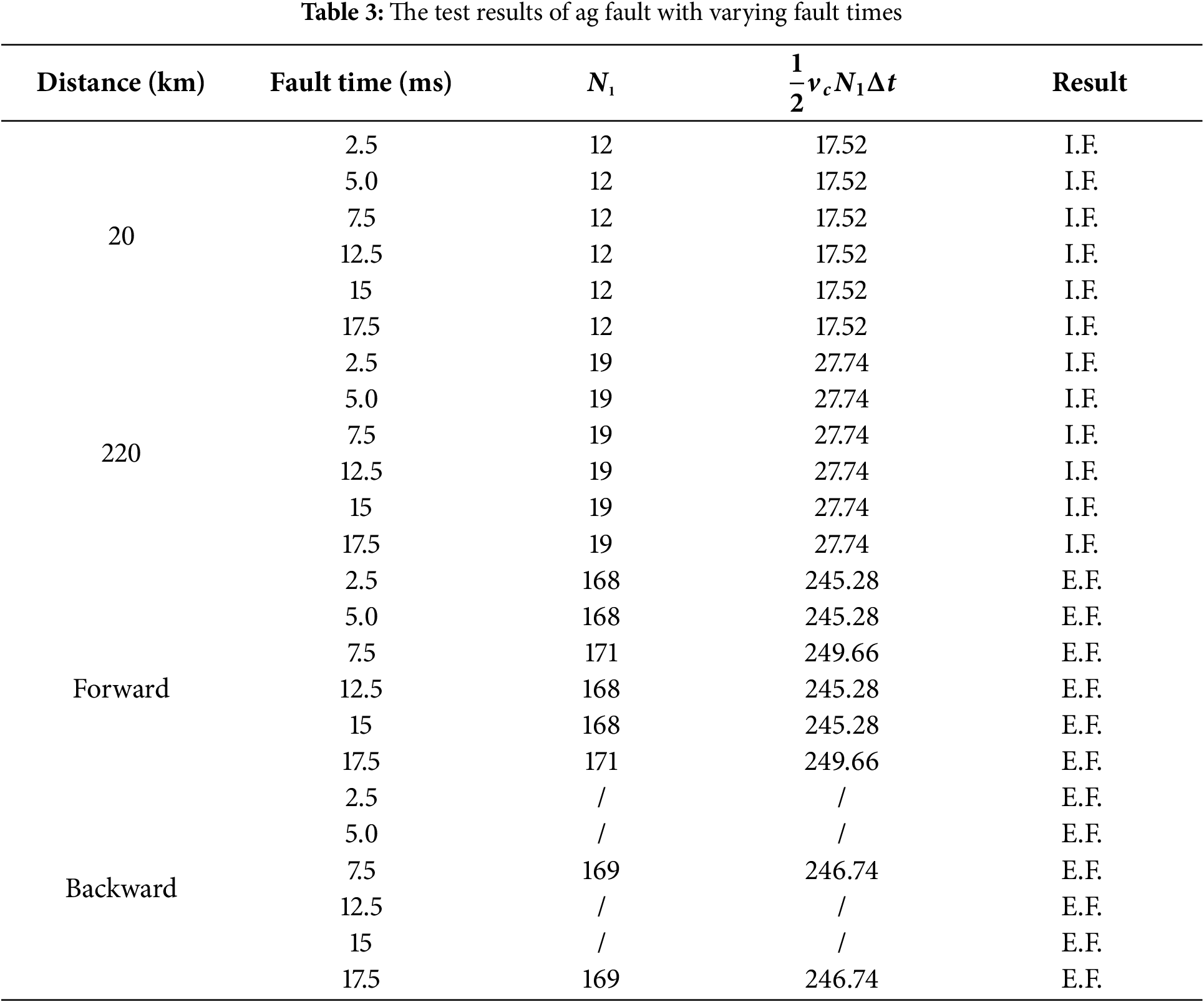
The transient response of AC transmission line faults exhibits significant dependence on fault time. Multiple AG fault scenarios with varying fault times are emulated to validate the performance of the proposed protection. Table 3 shows the test results. Table 3 confirms the immunity to fault timing variations of the proposed protection, enabling consistent internal and external fault identification.
4.3 Discussion about the Influence of Measuring Noise
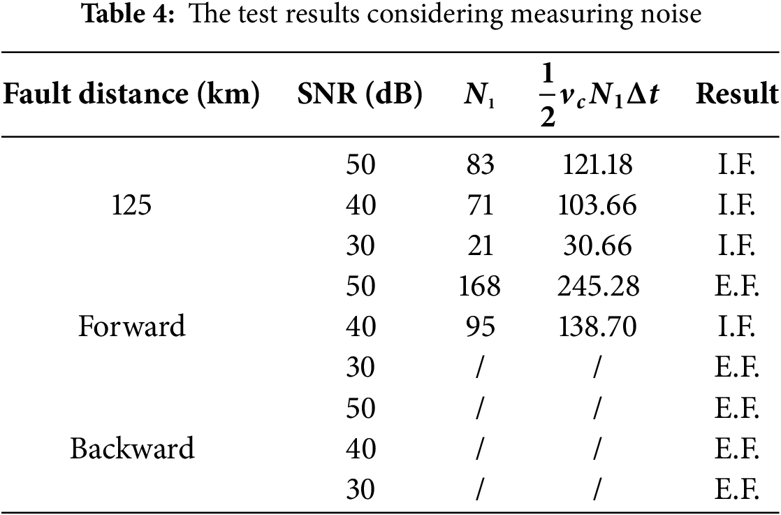
To investigate the impact of measurement noise on the performance of the proposed protection, Gaussian white noise was added to the current and voltage sampling signals in simulated phase A grounding fault scenarios with varying fault distances, thereby validating the performance of the proposed method. Table 4 shows the test results. In the table, “SNR” denotes the signal-to-noise ratio, and a smaller SNR value indicates higher measurement noise. From Table 4, the proposed protection scheme is susceptible to noise interference. As the SNR decreases, while the protection can still correctly identify internal faults occurring at the line midpoint, its performance gradually deteriorates. More critically, maloperation cases even happen due to external faults. Therefore, to further enhance the reliability of the proposed protection, incorporating filtering devices to operate in conjunction with the protection could be considered.
A non-unit protection method based on the propagation process of the fault traveling wave is proposed here. After a fault occurs, a fault traveling wave emanates from the fault point and propagates bidirectionally toward terminals. Analysis shows that the temporal interval between the initial and secondary arrivals of the fault backward traveling wave at the measurement point can reflect the fault location. Based on the analysis, the temporal interval between the initial and secondary arrivals of the α-mode component fault backward traveling wave is used to form the protection criterion, and the Teager energy operator is applied to obtain the time difference. Different fault scenarios are simulated in PSCAD to test the performance of the proposed method.
Theoretical analysis and simulation verification demonstrate that the proposed method can effectively identify internal and external faults under different fault scenarios, while offering the following advantages:
(a) The proposed protection method requires only a sampling time window of 2 ms before and after protection initiation, ensuring a fast operation speed.
(b) Within the required 4 ms sampling time window, the control strategies of renewable energy sources will not be activated. The changes in fault current and voltage depend solely on the inherent system topology, rendering the proposed protection immune to the influence of integrating renewable energy sources.
(c) The proposed protection algorithm involves only simple counting and basic arithmetic operations, making it easy to implement.
The proposed protection is suitable for us as the main protection for transmission lines. Indeed, the proposed protection still has certain limitations, such as susceptibility to measurement noise. To enhance the reliability of the proposed protection, consideration could be given to incorporating a filter to cooperate with it.
Acknowledgement: Not applicable.
Funding Statement: This research was funded in part by Science and Technology Project of State Grid Sichuan Electric Power Company under Grant 521997230003.
Author Contributions: The authors confirm contribution to the paper as follows: Conceptualization, Hao Wang; methodology, Hao Wang; software, Yiping Luo; validation, Wenyue Zhou; writing—original draft preparation, Hao Wang; writing—review and editing, Wenyue Zhou and Yiping Luo. All authors reviewed the results and approved the final version of the manuscript.
Availability of Data and Materials: Not applicable.
Ethics Approval: Not applicable.
Conflicts of Interest: The authors declare no conflicts of interest to report regarding the present study.
References
1. Yang Z, Wang H, Liao W. Protection challenges and solutions for AC systems with renewable energy sources: a review. Prot Control Mod Power Syst. 2025;10(1):18–39. doi:10.23919/PCMP.2023.000279. [Google Scholar] [CrossRef]
2. Zheng X, Chao C, Weng Y, Ye H, Liu Z, Gao P, et al. High-frequency fault analysis-based pilot protection scheme for a distribution network with high photovoltaic penetration. IEEE Trans Smart Grid. 2023;14(1):302–14. doi:10.1109/TSG.2022.3203392. [Google Scholar] [CrossRef]
3. Chen F, Xue M, Qiu Y, Yang L, Chen Q, Yu C, et al. Multi-terminal wireless differential protection method for offshore wind power collection lines. IEEE Access. 2024;12(5):58789–800. doi:10.1109/ACCESS.2024.3392570. [Google Scholar] [CrossRef]
4. Quispe JC, Orduña E. Transmission line protection challenges influenced by inverter-based resources: a review. Prot Control Mod Power Syst. 2022;7(3):1–17. doi:10.1186/s41601-022-00249-8. [Google Scholar] [CrossRef]
5. Muljadi E, Samaan N, Gevorgian V. Different factors affecting short circuit behavior of a wind power plant. IEEE Trans Ind Appl. 2013;49(1):284–92. doi:10.1109/TIA.2012.2228831. [Google Scholar] [CrossRef]
6. Saleh SA, Aljankawey AS, Abu-Khaizaran MS. Influences of power electronic converters on voltage–current behaviors during faults in DGUs—part I: wind energy conversion systems. IEEE Trans Ind Appl. 2015;51(4):2819–31. doi:10.1109/TIA.2014.2387477. [Google Scholar] [CrossRef]
7. Saleh SA, Aljankawey AS, Alsayid B. Influences of power electronic converters on voltage–current behaviors during faults in DGUs—part II: photovoltaic systems. IEEE Trans Ind Appl. 2015;51(4):2832–45. doi:10.1109/TIA.2014.2387482. [Google Scholar] [CrossRef]
8. Chandrasekar S, Gokaraju R. Dynamic phasor modeling of type 3 DFIG wind generators (including SSCI phenomenon) for short-circuit calculations. IEEE Trans Power Deliv. 2015;30(2):887–97. doi:10.1109/TPWRD.2014.2365587. [Google Scholar] [CrossRef]
9. Howard DF, Habetler TG, Harley RG. Improved sequence network model of wind turbine generators for short-circuit studies. IEEE Trans Energy Convers. 2012;27(4):968–77. doi:10.1109/TEC.2012.2213255. [Google Scholar] [CrossRef]
10. Hooshyar A, Azzouz MA, El-Saadany EF. Distance protection of lines connected to induction generator-based wind farms during balanced faults. IEEE Trans Sustain Energy. 2014;5(4):1193–203. doi:10.1109/TSTE.2014.2336773. [Google Scholar] [CrossRef]
11. Zhou Z, Yu S, Wang X. A new distance protection method using calculated voltage as polarization voltage for renewable energy system. In: Proceedings of the 18th International Conference on Developments in Power System Protection; 2025 Jan 8–11; Hong Kong, China. p. 278–82. doi:10.1049/icp.2025.0481. [Google Scholar] [CrossRef]
12. Li B, Sheng Y, He J. Improved distance protection for wind farm transmission line based on dynamic frequency estimation. Int J Electr Power Energy Syst. 2023;153(1):109382. doi:10.1016/j.ijepes.2023.109382. [Google Scholar] [CrossRef]
13. Mishra P, Pradhan AK, Bajpai P. Adaptive distance relaying for distribution lines connecting inverter-interfaced solar PV plant. IEEE Trans Ind Electron. 2021;68(3):2300–9. doi:10.1109/TIE.2020.2975462. [Google Scholar] [CrossRef]
14. Ma K, Høidalen HK, Chen Z. Improved zone 1 top line tilting scheme for the polygonal distance protection in the outgoing line. CSEE J Power Energy Syst. 2023;9(1):172–84. doi:10.17775/CSEEJPES.2021.07870. [Google Scholar] [CrossRef]
15. Zhang Y, Zhang G, Wang G, Mo C, Liu Z, Sun Y, et al. Algorithm for pilot current differential protection based on wideband quantities. In: Proceedings of the 2025 7th International Conference on Information Science, Electrical and Automation Engineering; 2025 Apr 18–20; Harbin, China. p. 1094–7. doi:10.1109/ISEAE64934.2025.11041905. [Google Scholar] [CrossRef]
16. Sadegh H. A novel method for adaptive distance protection of transmission line connected to wind farms. Int J Electr Power Energy Syst. 2012;43(1):1376–82. doi:10.1016/j.ijepes.2012.06.072. [Google Scholar] [CrossRef]
17. Chen Y, Wen M, Yin X. Distance protection for transmission lines of DFIG-based wind power integration system. Int J Electr Power Energy Syst. 2018;100(6–7):438–48. doi:10.1016/j.ijepes.2018.02.041. [Google Scholar] [CrossRef]
18. Hu Z, Li B, Zheng Y, Wu T, He J, Yao B, et al. Fast distance protection scheme for wind farm transmission lines considering RL and Bergeron models. J Mod Power Syst Clean Energy. 2023;11(3):840–52. doi:10.35833/MPCE.2021.000423. [Google Scholar] [CrossRef]
19. Singh P, Pradhan A. A local measurement-based protection technique for distribution system with photovoltaic plants. IET Renew Power Gener. 2020;14(6):996–1003. doi:10.1049/iet-rpg.2019.0996. [Google Scholar] [CrossRef]
20. Huang W, Nengling T, Zheng X, Fan C, Yang X, et al. An impedance protection scheme for feeders of active distribution networks. IEEE Trans Power Deliv. 2014;29(4):1591–602. doi:10.1109/TPWRD.2014.2322866. [Google Scholar] [CrossRef]
21. Chen G, Liu Y, Yang Q. Impedance differential protection for active distribution network. IEEE Trans Power Deliv. 2020;35(1):25–36. doi:10.1109/TPWRD.2019.2919142. [Google Scholar] [CrossRef]
22. Jia K, Xuan Z, Feng T. Transient high-frequency impedance comparison-based protection for flexible DC distribution systems. IEEE Trans Smart Grid. 2020;11(1):323–33. doi:10.1109/TSG.2019.2921387. [Google Scholar] [CrossRef]
23. Li Z, Xiao R, Du Y, Ren S, Tang P, Yan X. Fault transient analysis and protection for transmission lines with integration of centralized photovoltaic. Autom Electr Power Syst. 2019;43(18):120–8. doi:10.7500/AEPS20181231004. [Google Scholar] [CrossRef]
24. Jia K, Yang Z, Wei C. Pilot protection based on spearman rank correlation coefficient for transmission line connected to renewable energy source. Autom Electr Power Syst. 2020;44(15):103–11. (In Chinese). doi:10.7500/AEPS20190630001. [Google Scholar] [CrossRef]
25. Zheng L, Jia K, Bi T. Comprehensive criteria of pilot protection based on structural similarity and square error for outgoing line from renewable power plants. Power Syst Technol. 2020;44(5):1788–95. (In Chinese). doi:10.13335/j.1000-3673.pst.2019.0934. [Google Scholar] [CrossRef]
26. Yang Z, Liao W, Bak CL. Comprehensive current amplitude ratio based pilot protection for line with converter-interfaced sources. Energy Rep. 2022;8(2):420–30. doi:10.1016/j.egyr.2022.05.170. [Google Scholar] [CrossRef]
27. Soleimanisardoo A, Karegar H, Zeineldin H. Differential frequency protection scheme based on off-nominal frequency injections for inverter-based islanded microgrids. IEEE Trans Smart Grid. 2019;10(2):2107–14. doi:10.1109/TSG.2017.2788851. [Google Scholar] [CrossRef]
28. EL-Sayed W, EL-Saadany E, Zeineldin H. Interharmonic differential relay with a soft current limiter for the protection of inverter-based islanded microgrids. IEEE Trans Power Deliv. 2021;36(3):1349–59. doi:10.1109/TPWRD.2020.3006791. [Google Scholar] [CrossRef]
Cite This Article
 Copyright © 2025 The Author(s). Published by Tech Science Press.
This work is licensed under a Creative Commons Attribution 4.0 International License , which permits unrestricted use, distribution, and reproduction in any medium, provided the original work is properly cited.
 Downloads
 Citation Tools