
 Submit a Paper
 Propose a Special lssue
 Open Access
ARTICLE

Fault Self-Healing Cooperative Strategy of New Energy Distribution Network Based on Improved Ant Colony-Genetic Hybrid Algorithm
Dongguan Power Supply Bureau of Guangdong Power Grid Co., Ltd., Dongguan, China
* Corresponding Author: Fengchao Chen. Email:
(This article belongs to the Special Issue: Advanced Analytics on Energy Systems)
Energy Engineering 2026, 123(4), 11 https://doi.org/10.32604/ee.2026.072188
Received 21 August 2025; Accepted 11 November 2025; Issue published 27 March 2026
 View Full Text
 Download PDF
Abstract
With the high proportion of new energy access, the traditional fault self-healing mechanism of the distribution network is challenged. Aiming at the demand for fast recovery of new distribution network faults, this paper proposes a fault self-healing cooperative strategy for the new energy distribution network based on an improved ant colony-genetic hybrid algorithm. Firstly, the graph theory adjacency matrix is used to characterize the topology of the distribution network, and the dynamic positioning of new energy nodes is realized. Secondly, based on the output model and load characteristic model of wind, photovoltaic, and energy storage, a two-layer cooperative self-healing model of the distribution network is constructed. The upper layer is based on the improved depth-breadth hybrid search (DFS-BFS) to divide the island, with the maximum weight load recovery and the minimum number of switching actions as the goal, combined with the load priority to dynamically restore the key load. The lower layer uses the improved ant colony-genetic hybrid algorithm to solve the fault recovery path with the minimum total power loss load and the minimum network loss as the goal, generate the optimal switching sequence, and verify the power flow constraints. Finally, the simulation results based on the IEEE 33-bus system show that the proposed method can guarantee the power supply of key loads in the distribution network with high-tech energy penetration, restore the power supply of more load nodes with the least switching operation, and effectively reduce the line loss, which verifies the effectiveness and superiority of the method.Keywords
With the deepening of the “double carbon” strategy, the penetration rate of new energy represented by wind power and photovoltaic in the distribution network continues to rise. However, the high proportion of new energy access leads to the characteristics of strong uncertainty, weak inertia support, and multiple control dimensions in the distribution network [1], which makes the traditional fault self-healing mechanism based on centralized control of the master station face severe challenges [2,3]. For example, the topology adaptability is poor, and the traditional admittance matrix method is difficult to dynamically track the location of distributed generation (DG) nodes. The random fluctuation of new energy output leads to the risk of island power imbalance, and a single algorithm is difficult to balance the recovery speed and recovery quality.
At present, scholars’ research on fault self-healing of new energy distribution network includes: model construction and collaborative recovery strategy of diversified flexible resources such as source-grid-load-storage [4], core problems and characteristics of fault recovery [5], and key technologies for improving the resilience of distribution network [6]. At present, the solution methods of distribution network fault recovery mainly include mathematical optimization algorithms [7], heuristic search algorithms [8,9], and intelligent optimization algorithms [10–12]. References [8,9] proposed a distribution network fault recovery strategy based on the combination of heuristic rules and algorithms for distribution networks with high-permeability distributed power sources, but it is easy to fall into a local optimum. References [10,11] established a model considering distributed generation, combined island division with network reconfiguration, and used intelligent algorithms to solve it. In Reference [12], a fault recovery strategy for a distribution network under a multi-agent system is proposed. Based on the improved ant colony algorithm, the established cooperative recovery model is solved, but the distributed new energy is not considered. In Reference [13], a fault recovery strategy considering both network reconfiguration and islanding is proposed. The fault recovery model is solved efficiently by the combination of second-order cone and relaxation technology, but it is difficult to ensure that the solution is the optimal solution that satisfies the constraints.
Reference [14] used an ant colony algorithm to improve the fault recovery model of the distribution network. In the study of load shedding [15], the binary particle swarm optimization algorithm (BPSO) is applied to ensure that the particles can obtain the optimal solution under the condition of satisfying the constraints. Reference [16] used a genetic algorithm (GA) to optimize the fault recovery strategy with the minimum number of power loss loads as the objective function. However, intelligent algorithms such as the ant colony algorithm, particle swarm algorithm [17,18], and GA [19,20] have their own defects. Combining two or more algorithms and using complementary advantages can make up for the shortcomings of the algorithm itself [21].
In summary, in order to meet the needs of rapid recovery of new distribution network faults, this paper proposes a self-healing collaborative strategy for new energy distribution network faults based on an improved ant colony-genetic hybrid algorithm. Construct a two-layer collaborative self-healing model for the distribution network: The upper layer conducts island division based on the improved depth-breadth hybrid search (DFS-BFS), aiming at maximum weight load recovery and minimum number of switching actions, and dynamically recovers key loads in combination with load priority. The bottom layer adopts an improved ant colony genetic hybrid algorithm, aiming at minimizing the total loss load and network loss, to solve the fault recovery path and generate the optimal handover sequence. The results show that the proposed method can ensure the power supply of key loads in the high-tech energy penetration distribution network and effectively reduce line losses.
2 Topology Identification of New Energy Distribution Network Based on Graph Theory
2.1 Graph Theory Basic Modeling
Graph theory modeling uses graph data to characterize the topological structure and electrical characteristic information of a new energy distribution network, and abstracts the distribution network with new energy into a weighted directed graph [22], that is
Among them,
Tag node attribute: the attribute of
The topological structure of a distribution network is commonly expressed by an adjacency matrix. The topological structure matrix
2.2 Topology Reconstruction Rules
During the operation of the new energy distribution network, its topology will change with the change of the switching state. Topology reconfiguration is to dynamically update the topology connection relationship of the distribution network according to the change of switch state. The state function of the switch
Among them, t is the time; k is the kth switch. then the switch state variation can be expressed as:
After adding the state of the switch, the update rule of the edge set
At the same time, the constraints of topology reconstruction are established.
(1) Radial constraint
The effective topology should satisfy:
(2) Connectivity constraint
For any load node
(3) Electrical safety constraints
Any node voltage needs to meet the voltage deviation constraint:
At the same time, meet the line capacity constraints:
2.3 New Energy Island Formation Rules
In the new energy distribution network, because the distributed new energy is used as the power point, when the main power supply is disconnected, an island can be formed with the new energy as the center [23]. Therefore, it is necessary to establish the judgment conditions of the new energy island:
And meet the power balance constraints and voltage stability constraints.
The power balance constraint can be expressed as:
Among them, the available power
The island must have enough voltage support nodes, so the voltage stability constraint can be expressed as:
3 Wind-Solar-Storage-Load Model
3.1 Wind-Solar-Storage Output Model
Solar radiation intensity is a key factor affecting the output power of photovoltaic generators. The relationship between photovoltaic output and solar radiation intensity can be expressed as:
Among them,
The output power of the wind turbine is mainly affected by the local wind speed. The relationship between the output power and the wind speed can be expressed as follows:
Among them,
It can be seen from Eq. (11) that when the wind speed is lower than the cut-in wind speed or greater than the cut-out wind speed, the wind turbine does not output; when the wind speed is higher than the rated wind speed and lower than the cut-out wind speed, the wind turbine issues a rated power.
3.1.3 Energy Storage System Model
The charging and discharging model of the energy storage system is simplified into a linear model in the normal operation interval, and the simplified charging and discharging models can be expressed as:
Charging model:
Discharge model:
Among them,
At the same time, the energy storage system model needs to consider the maximum power limit of charging and discharging and the energy storage capacity limit. The constraint conditions can be expressed as:
Among them,
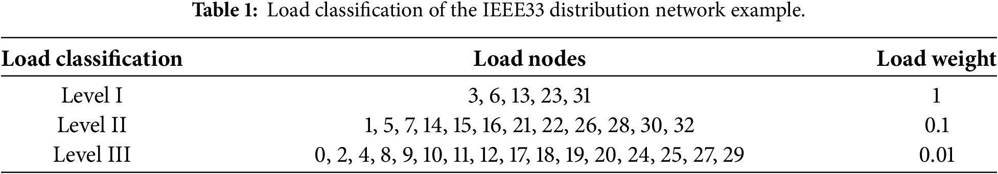
3.2.1 Load Classification Model
In order to ensure the power supply reliability of important loads and optimize the allocation of resources, the power load is usually divided into primary, secondary and tertiary according to the degree of safety and economic impact that may be caused by the interruption of power supply [24]. The first-level load must quickly restore power supply when the distribution network fails, and the second-level and third-level loads are sorted in turn. Therefore, for different types of loads, the order of power supply restoration is determined according to their importance in the scene at that time. Therefore, the recovery power supply coefficient of the load is established, which can be expressed as:
Among them,
During the fault recovery period, the load is sorted from large to small according to
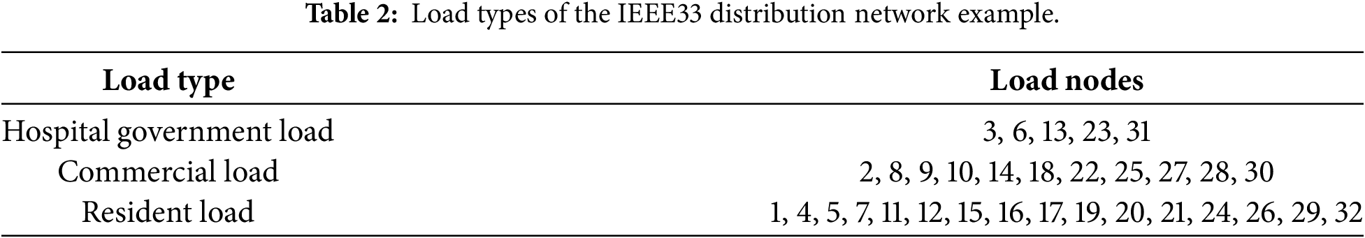
Different load types have different characteristics in different time periods [25]. Fig. 1 is the typical daily load curve of hospital government load, resident load, and commercial load. By integrating the typical daily load curve, the power demand of different types of loads changing with time can be obtained, that is, the time-varying model of load:
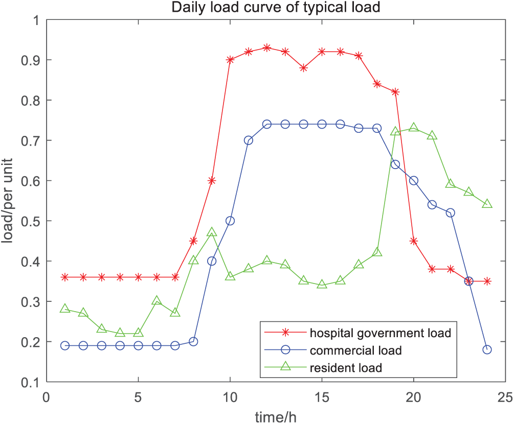
Figure 1: Daily load curve of typical load.
Among them,
4 Double-Layer Cooperative Self-Healing Model of Distribution Network
4.1 Upper Layer: Island Division Based on Improved Depth-Breadth Hybrid Search
After the failure of the new energy distribution network, the stable island is quickly constructed, and the power supply of important loads is restored according to the load priority recovery set
The island division takes the maximum weight load recovery and the minimum number of switching actions as the goal, and combines the load priority to dynamically restore the key load. Therefore, the objective function of island partition can be expressed as follows:
Among them,
(1) Power constraint on the island
Among them,
(2) Power balance constraints
Among them,
(3) Branch capacity and current constraints
Among them,
Among them,
(4) Network radial constraints
Among them,
4.1.3 Island Partition Based on Improved DFS-BFS Hybrid Search
In this paper, a hybrid search method combining depth-first search Depth-First Search (DFS) and breadth-first search Breadth-First Search (BFS) is used to search the new energy distribution network topology in the process of island division. DFS quickly penetrates the network and locks the new energy-intensive area as an ‘island seed’, while BFS expands from the ‘seed’ to the outside layer, preferentially accessing high-weight loads to ensure the fairness and efficiency of fault recovery. The specific island division process can be described as follows [28]:
(1) DFS positioning the new energy core position
Taking the new energy node as the starting point, the depth search is carried out along the feeder; in order to prevent too far a search, the search depth
Among them,
Search backtracking conditions (immediately stop the search and return):
1. Out-of-limit voltage
2. Loading rate of transmission line > 90%;
3. Fault equipment encountered.
(2) BFS layered load expansion
Starting from
In the search process, each extended layer needs to calculate the real-time power flow,
(3) Island stability optimization
If the island voltage fluctuation continues to be >2%, the secondary adjustment is started, that is, the energy storage device is put into operation to provide reactive power support. If there is wind power, the pitch angle of the fan is adjusted to have less active fluctuation.
4.2 The Lower Layer: Fault Recovery Strategy Based on an Improved Ant Colony-Genetic Hybrid Algorithm
Aiming at minimizing the total power loss load and network loss, the fault recovery path is solved to recover the high-demand load in a limited way, while avoiding the surge of line loss caused by long-distance power supply, so as to generate the optimal switching sequence and verify the power flow constraints [29,30]. Therefore, the objective function of the fault recovery strategy can be expressed as:
Among them,
The implementation of the lower-level fault recovery strategy also needs to meet multiple constraints.
(1) Topological constraint
The new energy distribution network is guaranteed to operate in a radial network structure, a loopless network form, and the topology constraints are defined as follows:
Among them,
(2) Voltage and current constraints
The voltage complies with the allowable deviation stipulated in the Chinese national standard “Power quality—Deviation of supply voltage”, and the current meets the safety margin of the line.
(3) Power constraints
It should ensure that the total output of all available power sources has a total load demand and a 10% power reserve, that is:
(4) Switch operation interval constraint
In order to prevent the mechanical misoperation of the switch, the operation time interval of the adjacent switch is required to be not less than 2 s, that is:
where
4.2.3 Fault Recovery Based on an Improved Ant Colony-Genetic Hybrid Algorithm
The ant colony algorithm adopts a positive feedback mechanism. The principle of solving the shortest path is that the ants choose the next path according to the pheromone concentration left by the previous ants. However, the quality of the initial solution of the ant colony algorithm depends on the parameters, and it is easy to fall into a local optimum. The genetic algorithm is a group iterative algorithm. Starting from any initial solution generated, it simulates the mechanism of the survival of the fittest of organisms, through selection, crossover and mutation operations, until the optimal solution is found. The genetic algorithm has a large-scale and diversified initial population, the population efficiency is low, and the convergence speed of the algorithm is slow.
The fault recovery of a new energy distribution network is a typical combinatorial optimization problem. The search space of switch operation sequence increases exponentially with the number of switches, and the traditional mathematical programming method is difficult to solve in real time [31]. Therefore, this paper adopts the improved ant colony-genetic hybrid algorithm, uses the positive feedback mechanism of the ant colony algorithm to guide the ants to gather to the high-quality solution area with pheromones, and quickly generates the high-quality initial solution. Then, the genetic algorithm is used to search in depth in the field of high-quality solutions delineated by the ant colony. The diversity and global optimality of the solution are guaranteed by selection-cross-mutation, and the optimal operation sequence of the fault recovery switch is obtained.
The implementation process of the fault recovery strategy based on an improved ant colony-genetic hybrid algorithm is shown in Fig. 2, which can be divided into the ant colony optimization stage, the genetic optimization stage, and the hybrid coordination stage.
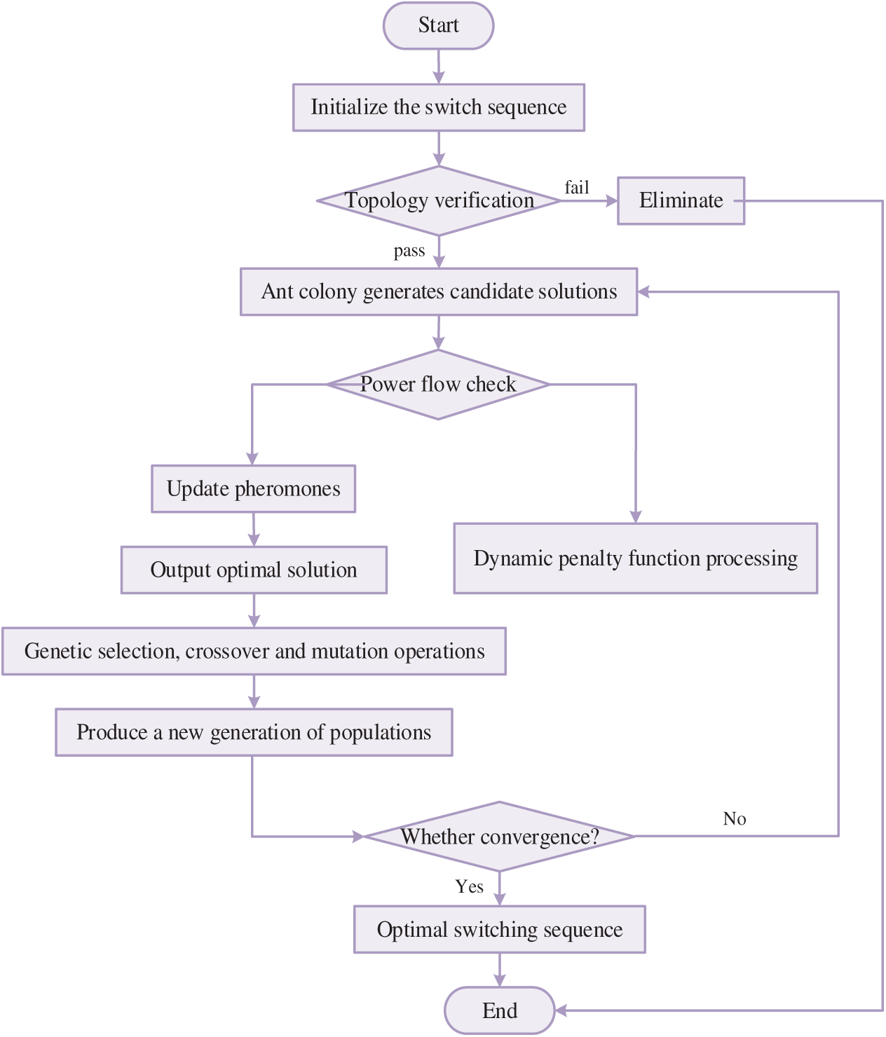
Figure 2: Flow chart of fault recovery strategy based on improved ant colony-genetic hybrid algorithm.
(1) Ant colony optimization stage: switch path search
The ant colony optimization stage includes the state transition probability and the pheromone update mechanism.
1. State transition rule
Among them,
2. Pheromone update mechanism
Among them,
(2) Genetic optimization stage: global optimization
In the genetic optimization stage, the operation sequence of the switch is first encoded with a binary string, 1 indicates that the switch is closed, and 0 indicates that the switch is disconnected.
The genetic selection operation adopts the roulette strategy, and the selection probability
The genetic crossover operation is to randomly select two crossover points, exchange the gene fragments of two parent individuals between the two points, and maintain the feasible sequence.
The genetic variation operation flips the gene locus with a mutation probability, and the mutation probability decays with time:
(3) Hybrid collaboration phase
Based on the improved ant colony-genetic hybrid algorithm, the first 20% of the optimal solution obtained by ant colony optimization is added to the initial population of the genetic algorithm, and then the optimal solution of each generation of the genetic algorithm is used to update the pheromone, that is:
where
For infeasible solutions, a dynamic penalty function is set:
The penalty coefficient
And, a flowchart for self-healing of faults is shown in Fig. 3. The detailed steps are as follows:
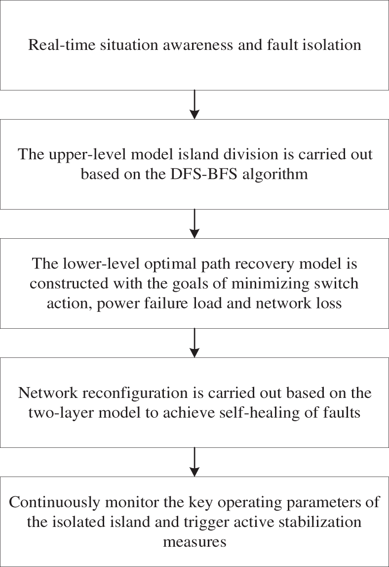
Figure 3: Self-healing process for faults.
First, upon the occurrence and isolation of a permanent fault, the process is initiated. The system enters a state of real-time situational awareness, where the graph theory-based adjacency matrix is dynamically updated to reflect the new network topology with the faulted section isolated. Concurrently, real-time data on the output of wind, photovoltaic, and energy storage systems, as well as the time-varying demand of loads, is aggregated to form an accurate snapshot of system conditions.
Subsequently, the upper-layer model performs strategic island formation. The improved DFS-BFS algorithm utilizes the real-time data to dynamically identify viable microgrids. It begins by locating “island seeds” around distributed energy resources using a depth-first search and then expands these seeds through a breadth-first search, preferentially incorporating high-priority loads while strictly adhering to radiality, power balance, and voltage constraints. This stage determines the optimal boundaries for self-sustaining islands, effectively deciding which loads can be restored locally and where.
Following the island division, the lower-layer model executes optimal path restoration for the remaining non-islanded, de-energized sections. The improved ant colony-genetic hybrid algorithm solves for the optimal sequence of switch operations to re-energize these areas from the main grid or adjacent stable islands. This step focuses on how to restore the remaining network with minimal switching operations, lost load, and network losses, thereby complementing the strategic decision of the upper layer with tactical pathfinding.
The process then transitions from computation to physical action. The calculated switching sequence—encompassing both the island formation and network reconfiguration—is executed by sending commands to remote-controlled switches. This constitutes the physical reconfiguration of the network, where islands are energized and tie-switches are closed to back-feed power, transforming the algorithmic solution into a new, stable operating topology.
Finally, a post-restoration monitoring and stabilization phase ensures ongoing resilience. The system continuously monitors key parameters within the newly formed islands.
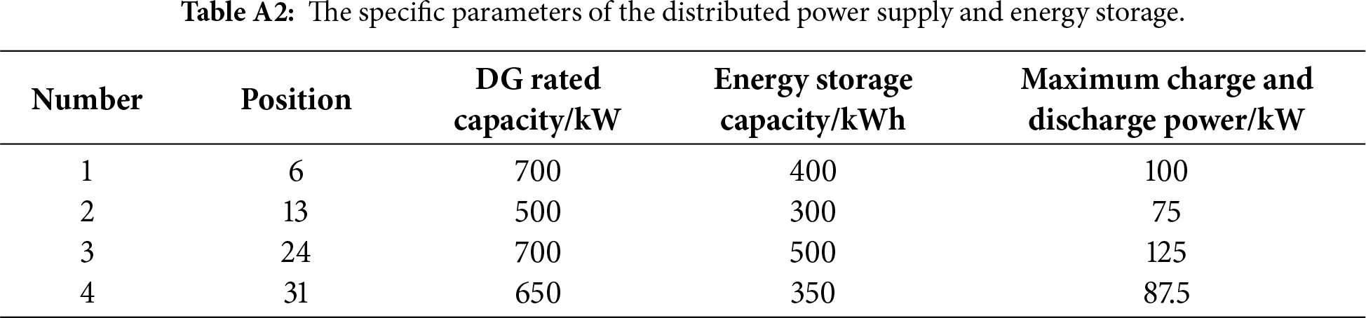
In order to verify the effectiveness of the proposed fault self-healing coordination strategy of the new energy distribution network based on an improved ant colony-genetic hybrid algorithm, this paper is based on the IEEE33 node distribution network example model [32,33], as shown in Fig. 4. The node is the load access point, with a total of 37 branches, of which 5 branches include contact switches, and the remaining branches include segmented switches. Nodes 6 and 13 are connected to distributed photovoltaic and energy storage, and nodes 23 and 31 are connected to wind power and energy storage.
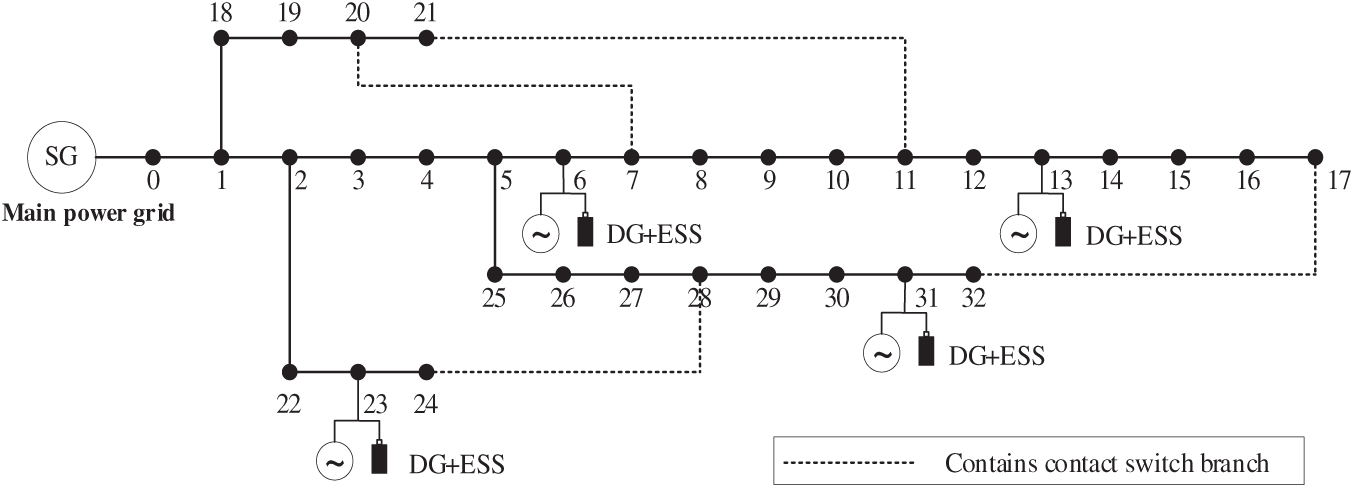
Figure 4: IEEE33 node new energy distribution network example model.
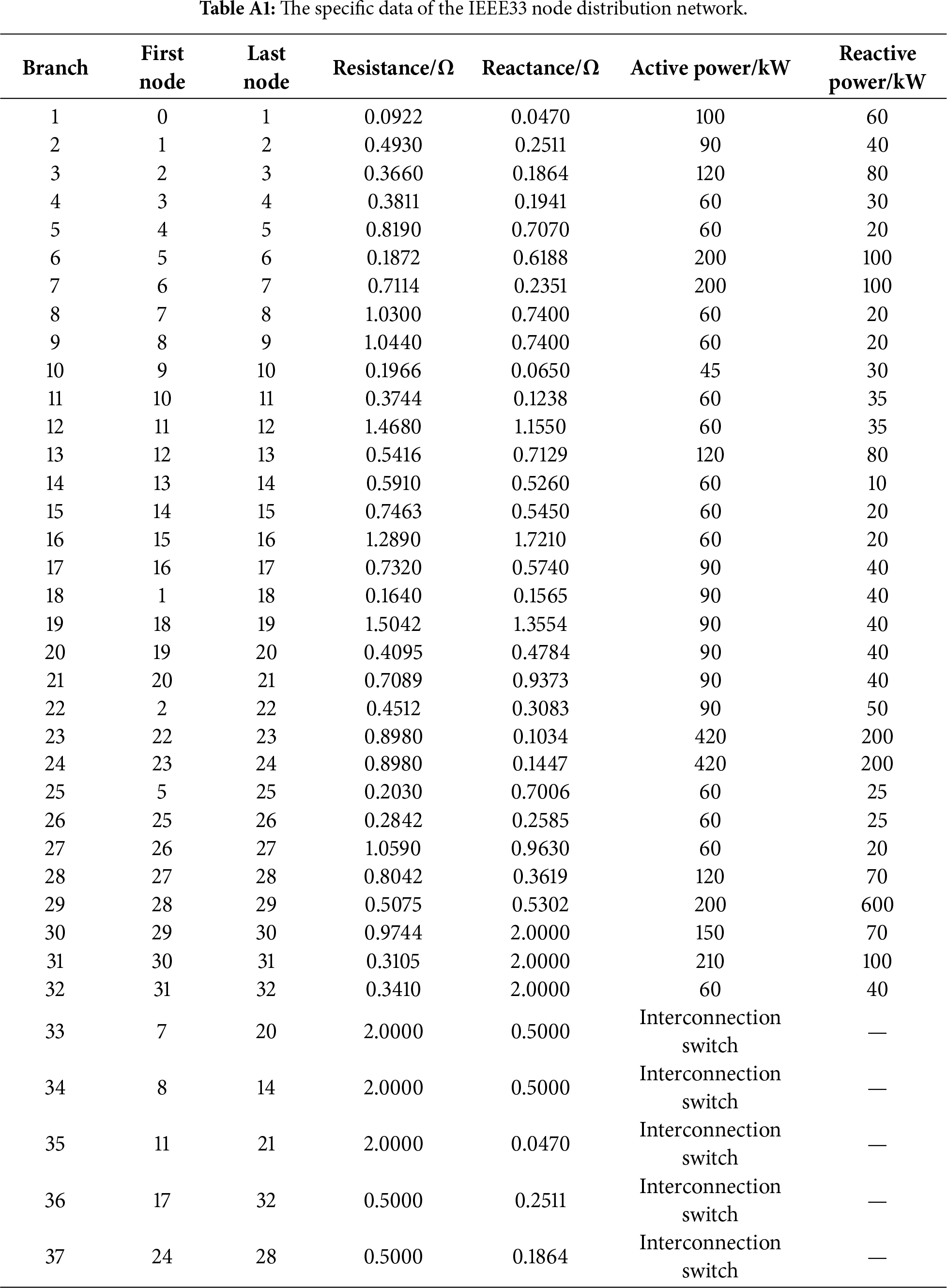
The specific data of the IEEE33 node distribution network is shown in Table A1, and the specific parameters of the distributed power supply and energy storage are shown in Table A2.
The load classification and load type of the IEEE33 distribution network example are shown in Tables 1 and 2, respectively.
5.2 Analysis of Island Division Results
The faults occurred respectively in branches 8–9 at 15:00 and branches 2–22 at 20:00. The fault point section switch is disconnected first to isolate the fault branch. Then the recovery power supply coefficient
The
According to the results of the island division, the fault branch and the island area branch are disconnected and isolated from the distribution network. The remaining section switches and contact switches in the distribution network are renumbered, and the improved depth-breadth hybrid search is used to divide the island, as shown in Fig. 5.
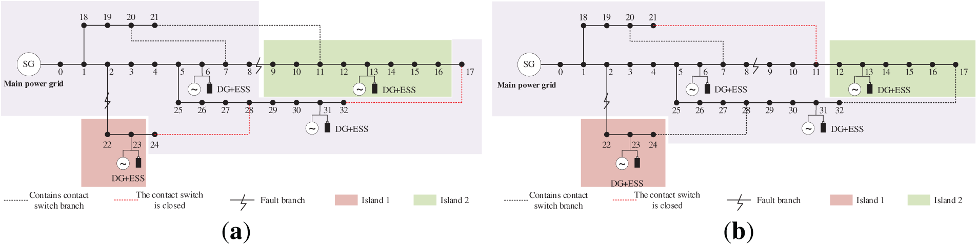
Figure 5: Results of island division in different periods. (a) Island division of 15:00 fault; (b) Island division of 20:00 fault.
5.3 Comparison of the Effect of Fault Recovery Strategy Based on Improved Ant Colony-Genetic Hybrid Algorithm
In order to verify the effectiveness of the fault recovery strategy, this paper uses three schemes to recover the same fault at the same fault time.
Scheme 1: This method is adopted, but the stability of distributed new energy and the time-varying demand of the load are not considered; that is, the energy storage device is not connected, and the time-varying demand difference of different types of loads is not considered.
Scheme 2: The method of this paper is used to recover the fault of the distribution network, and the uncertainty of the wind and light load is considered.
Scheme 3: The two-layer collaborative self-healing model of the distribution network in this paper is adopted, but the lower-layer algorithm adopts a genetic algorithm.
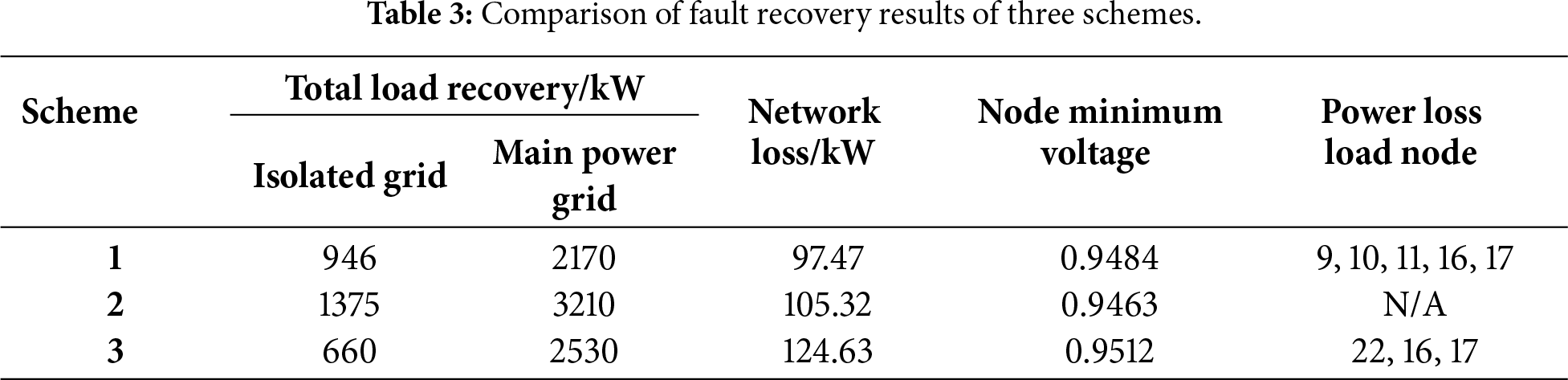
At 20:00, a fault occurs at branch 8–9 and branch 2–22. The fault recovery results of schemes 1 and 2 are shown in Fig. 6, and the fault recovery results are shown in Table 3.
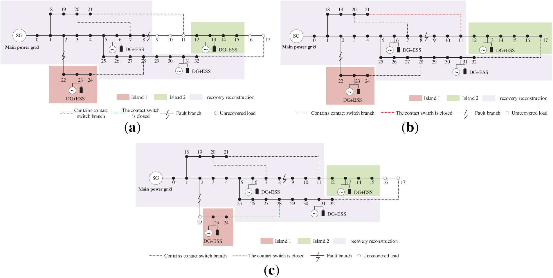
Figure 6: Fault recovery results of three schemes. (a) Scheme 1 Fault recovery result; (b) Scheme 2 Fault recovery result; (c) Scheme 3 Fault recovery result.
According to the comparison of the three fault recovery schemes in Fig. 6 and Table 3, it can be seen from the comparison results of the three fault recovery schemes that scheme 1 and scheme 3 can restore power supply to most of the power loss areas in the distribution network, but all the power loss load nodes cannot be restored. Among them, the scheme 3 algorithm does not make the optimal selection of the initial path, resulting in high network loss, being unable to close the contact switch, and using the main power grid to restore more power loss load nodes. The network loss of scheme 1 is slightly lower than that of scheme 2, but there is still a power loss load, and the island division range is small, so the important load cannot be restored preferentially. The fault recovery strategy adopted in this paper is better than scheme 1 and scheme 3, which can obtain the optimal strategy of distribution network fault recovery, restore all the power loss load, and reduce the network loss.
At the same time, this paper compares the convergence of the algorithm of scheme 2 and scheme 3, that is, the lower-layer algorithm of the double-layer collaborative self-healing model of the distribution network adopts the genetic algorithm and the improved ant colony-genetic hybrid algorithm. The convergence of the algorithm is compared, as shown in Fig. 7. It shows that the proposed algorithm takes into account the fast convergence of the fault recovery process while outputting the optimal strategy of distribution network fault recovery.
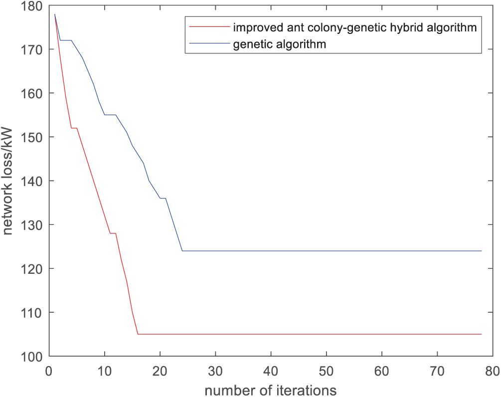
Figure 7: Comparison of algorithm convergence of scheme 2 and scheme 3.
In this paper, a fault self-healing collaborative strategy for new energy distribution networks based on an improved ant colony-genetic hybrid algorithm is proposed. The graph theory adjacency matrix is used to characterize the network topology, and a two-layer collaborative self-healing model is constructed based on the output/load characteristic models of wind energy, photovoltaics, and energy storage. The upper layer adopts the improved DFS-BFS (Depth-First Search-Breadth-First Search) for island division, while the lower layer uses the improved hybrid algorithm to solve the fault recovery path with minimal lost load and network loss. This ensures the supply of critical loads, restores more nodes with fewer switching operations, and reduces line losses. Simulations on the IEEE33 node system yield the following conclusions:
(1) Using the graph theory adjacency matrix to characterize the topology and dynamically locate new energy nodes, combined with the wind-solar-storage output and load models, not only provides an effective data foundation for upper-layer island division but also addresses the issue in existing methods where the dynamic locations of new energy nodes are ignored, which leads to inaccurate division. This ensures that island division takes into account the real-time nature of new energy supply and improves adaptability to high-proportion new energy. The improved DFS-BFS can generate reasonable island partitions that conform to the output characteristics of distributed energy resources, enhancing the feasibility of island operation after faults and solving the problem of “unusable” new energy in traditional strategies.
(2) The two-layer collaborative mechanism overcomes the problem that traditional single-algorithm strategies struggle to balance “island rationality” and “recovery efficiency”. The two-layer model decouples and collaboratively optimizes the two tasks: the upper-layer division provides a reasonable “solution space” for the lower-layer search, ensuring the overall strategy and local optimization efficiency. The improved hybrid algorithm reduces line losses and features fast convergence, addressing the problems of slow convergence of pure ant colony algorithms in large-scale networks and poor local optimization capabilities of pure genetic algorithms, thus providing a more effective tool for path solving. In general, this two-layer model provides a new methodological framework for fault self-healing of new energy distribution networks and lays a foundation for the intelligent and resilient development of future distribution networks.
Acknowledgement: Not applicable.
Funding Statement: This work was supported by the Installation of OCS Distribution Network Program Control 2.0 and Other Functions for Dongguan Power Supply Bureau of Guangdong Power Grid Co., Ltd. (No.: 031900GS62220049).
Author Contributions: The authors confirm contribution to the paper as follows: Fengchao Chen, Aoqi Mei: conceptualization, data curation, formal analysis; Zheng Liu, Ruhao Wu, Qiwei Li: funding acquisition, investigation, methodology, project administration, resources, software; Fengchao Chen: supervision, validation, visualization, writing—original draft, writing—review and editing. All authors reviewed and approved the final version of the manuscript.
Availability of Data and Materials: The data that support the findings of this study are available from the corresponding author on reasonable request.
Ethics Approval: Not applicable.
Conflicts of Interest: The authors declare no conflicts of interest.
Appendix A
References
1. Liu X, Jin F, Guo F, Yang J, Qian X, Feng D. A study on power supply restoration strategy considering flexible resource regulation ability. Eng Rep. 2024;6(12):e12953. doi:10.1002/eng2.12953. [Google Scholar] [CrossRef]
2. Sun Q, Wu Z, Ma Z, Gu W, Zhang XP, Lu Y, et al. Resilience enhancement strategy for multi-energy systems considering multi-stage recovery process and multi-energy coordination. Energy. 2022;241:122834. doi:10.1016/j.energy.2021.122834. [Google Scholar] [CrossRef]
3. Zhou S, Li Y, Jiang C, Xiong Z, Zhang J, Wang L. Enhancing the resilience of the power system to accommodate the construction of the new power system: key technologies and challenges. Front Energy Res. 2023;11:1256850. doi:10.3389/fenrg.2023.1256850. [Google Scholar] [CrossRef]
4. Wang X, Li Z, Shahidehpour M, Jiang C. Robust line hardening strategies for improving the resilience of distribution systems with variable renewable resources. IEEE Trans Sustain Energy. 2019;10(1):386–95. doi:10.1109/TSTE.2017.2788041. [Google Scholar] [CrossRef]
5. Cai S, Xie Y, Wu Q, Xiang Z. Robust MPC-based microgrid scheduling for resilience enhancement of distribution system. Int J Electr Power Energy Syst. 2020;121:106068. doi:10.1016/j.ijepes.2020.106068. [Google Scholar] [CrossRef]
6. Tang L, Han Y, Zalhaf AS, Zhou S, Yang P, Wang C, et al. Resilience enhancement of active distribution networks under extreme disaster scenarios: a comprehensive overview of fault location strategies. Renew Sustain Energy Rev. 2024;189:113898. doi:10.1016/j.rser.2023.113898. [Google Scholar] [CrossRef]
7. Andersson J, Grassi V, Mirandola R, Perez-Palacin D. A conceptual framework for resilience: fundamental definitions, strategies and metrics. Computing. 2021;103(4):559–88. doi:10.1007/s00607-020-00874-x. [Google Scholar] [CrossRef]
8. Wan H, Liu W, Zhang S, Shi Q, Cheng R, Feng W. Resilience-oriented load restoration method for power-gas-water systems considering public safety impact. IET Generation Trans Dist. 2024;18(21):3350–64. doi:10.1049/gtd2.13281. [Google Scholar] [CrossRef]
9. Koc E, Cetiner B, Rose A, Soibelman L, Taciroglu E, Wei D. CRAFT: comprehensive resilience assessment framework for transportation systems in urban areas. Adv Eng Inform. 2020;46:101159. doi:10.1016/j.aei.2020.101159. [Google Scholar] [CrossRef]
10. Wang Y, Xu Y, Li J, Li C, He J, Liu J, et al. Dynamic load restoration considering the interdependencies between power distribution systems and urban transportation systems. CSEE J Power Energy Syst. 2020;6(4):772–81. doi:10.17775/cseejpes.2020.02250. [Google Scholar] [CrossRef]
11. Chen L, Jiang Y, Deng X, Zheng S, Chen H, Islam MR. A multi-period restoration approach for resilience increase of active distribution networks by considering fault rapid recovery and component repair. Int J Electr Power Energy Syst. 2024;161(1):110181. doi:10.1016/j.ijepes.2024.110181. [Google Scholar] [CrossRef]
12. Huang F, Liu Z, Wang T, Zhang H, Yip T. The optimization study about fault self-healing restoration of power distribution network based on multi-agent technology. Comput Mater Contin. 2020;65(1):865–78. doi:10.32604/cmc.2020.010724. [Google Scholar] [CrossRef]
13. Li Y, Xiao J, Chen C, Tan Y, Cao Y. Service restoration model with mixed-integer second-order cone programming for distribution network with distributed generations. IEEE Trans Smart Grid. 2019;10(4):4138–50. doi:10.1109/TSG.2018.2850358. [Google Scholar] [CrossRef]
14. Peng Z, Zhang W, Xu W, Cai H, Zhao F, Han X, et al. Conditional value at risk-based island partitioning and fault restoration reconfiguration of active distribution networks. Front Energy Res. 2024;12:1460894. doi:10.3389/fenrg.2024.1460894. [Google Scholar] [CrossRef]
15. Yang L, Qin Y. Research on rolling co-optimization of fault repair and service restoration in distribution network based on combined drive methodology. Electr Power Syst Res. 2023;220:109373. doi:10.1016/j.epsr.2023.109373. [Google Scholar] [CrossRef]
16. Chang X, Xu Y, Sun H, Khan I. A distributed robust optimization approach for the economic dispatch of flexible resources. Int J Electr Power Energy Syst. 2021;124:106360. doi:10.1016/j.ijepes.2020.106360. [Google Scholar] [CrossRef]
17. Stefanidou-Voziki P, Sapountzoglou N, Raison B, Dominguez-Garcia JL. A review of fault location and classification methods in distribution grids. Electr Power Syst Res. 2022;209:108031. doi:10.1016/j.epsr.2022.108031. [Google Scholar] [CrossRef]
18. Golshani A, Sun W, Sun K. Advanced power system partitioning method for fast and reliable restoration: toward a self-healing power grid. IET Gener Transm Distrib. 2018;12(1):42–52. doi:10.1049/iet-gtd.2016.1797. [Google Scholar] [CrossRef]
19. Rajeswari K, Neduncheliyan S. Genetic algorithm based fault tolerant clustering in wireless sensor network. IET Commun. 2017;11(12):1927–32. doi:10.1049/iet-com.2016.1074. [Google Scholar] [CrossRef]
20. Ildarabadi R, Lotfi H, Hajiabadi ME, Nikkhah MH. Presenting a new mathematical modeling for distribution network resilience based on the optimal construction of Tie-lines considering importance of critical electrical loads. Electr Eng. 2024;106(3):2503–24. doi:10.1007/s00202-023-02077-x. [Google Scholar] [CrossRef]
21. Ji H, Wang C, Li P, Song G, Wu J. SOP-based islanding partition method of active distribution networks considering the characteristics of DG, energy storage system and load. Energy. 2018;155:312–25. doi:10.1016/j.energy.2018.04.168. [Google Scholar] [CrossRef]
22. Li C, Zhang D, Han J, Tian C, Xie L, Wang C, et al. A multi-level operation method for improving the resilience of power systems under extreme weather through preventive control and a virtual oscillator. Sensors. 2024;24(6):1812. doi:10.3390/s24061812. [Google Scholar] [PubMed] [CrossRef]
23. Tusher AS, Rahman MA, Islam MR, Hossain MJ. A comparative analysis of different transmission line fault detectors and classifiers during normal conditions and cyber-attacks. J Eng. 2024;2024(7):e12412. doi:10.1049/tje2.12412. [Google Scholar] [CrossRef]
24. Wang C, Zhang C, Luo L, Qi X, Kong J. Optimal resilience and risk-driven strategies for pre-disaster protection of electric power systems against uncertain disaster scenarios. Energies. 2024;17(15):3619. doi:10.3390/en17153619. [Google Scholar] [CrossRef]
25. Li ZL, Li P, Xia J, Yuan ZP. Cyber-physical-social system scheduling for multi-energy microgrids with distribution network coordination. Int J Electr Power Energy Syst. 2023;149:109054. doi:10.1016/j.ijepes.2023.109054. [Google Scholar] [CrossRef]
26. Dang J, Zhang S, Wang Y, Yan Y, Jia R, Liu G. Multi-objective power supply restoration in distribution networks based on graph calculation and information collected by multi-source sensors. Sensors. 2025;25(3):768. doi:10.3390/s25030768. [Google Scholar] [PubMed] [CrossRef]
27. Bai Y, Gu X, Li S, Liu K. Coordinated restoration method of transmission and distribution network considering distribution network fault repair scenario. Int J Electr Power Energy Syst. 2023;151:109153. doi:10.1016/j.ijepes.2023.109153. [Google Scholar] [CrossRef]
28. Liu W, Liu H, Hu Z, Luo Y. The restoration strategy for multiple faults in active distribution networks considering road-network coupling. Electron Lett. 2024;60(22):e70089. doi:10.1049/ell2.70089. [Google Scholar] [CrossRef]
29. Lin C, Chen C, Liu F, Li G, Bie Z. Dynamic MGs-based load restoration for resilient urban power distribution systems considering intermittent RESs and droop control. Int J Electr Power Energy Syst. 2022;140:107975. doi:10.1016/j.ijepes.2022.107975. [Google Scholar] [CrossRef]
30. Zhao J, Zhang M, Yu H, Ji H, Song G, Li P, et al. An islanding partition method of active distribution networks based on chance-constrained programming. Appl Energy. 2019;242:78–91. doi:10.1016/j.apenergy.2019.03.118. [Google Scholar] [CrossRef]
31. Chen C, Liu S, Cao Y, Tang L, Li Y. Optimal service restoration and adaptive switching of Tie switches method of distributed self-healing control in distribution systems. J Electr Eng Technol. 2023;18(5):3457–73. doi:10.1007/s42835-023-01463-6. [Google Scholar] [CrossRef]
32. Ma S, Chen B, Wang Z. Resilience enhancement strategy for distribution systems under extreme weather events. IEEE Trans Smart Grid. 2018;9(2):1442–51. doi:10.1109/TSG.2016.2591885. [Google Scholar] [CrossRef]
33. He C, Dai C, Wu L, Liu T. Robust network hardening strategy for enhancing resilience of integrated electricity and natural gas distribution systems against natural disasters. IEEE Trans Power Syst. 2018;33(5):5787–98. doi:10.1109/TPWRS.2018.2820383. [Google Scholar] [CrossRef]
Cite This Article
 Copyright © 2026 The Author(s). Published by Tech Science Press.
This work is licensed under a Creative Commons Attribution 4.0 International License , which permits unrestricted use, distribution, and reproduction in any medium, provided the original work is properly cited.
 Downloads
 Citation Tools