
 Submit a Paper
 Propose a Special lssue
 Open Access
ARTICLE

Active and Reactive Power Control of DFIG-Based Wind Farm Connected to IEEE 9-Bus System Network under Fault Condition
Department of Electrical Engineering, Central Institute of Technology Kokrajhar Deemed to be University, BTR, Kokrajhar, Assam, India
* Corresponding Author: Sanjit Brahma. Email:
Energy Engineering 2026, 123(4), 12 https://doi.org/10.32604/ee.2026.075245
Received 28 October 2025; Accepted 12 January 2026; Issue published 27 March 2026
 View Full Text
 Download PDF
Abstract
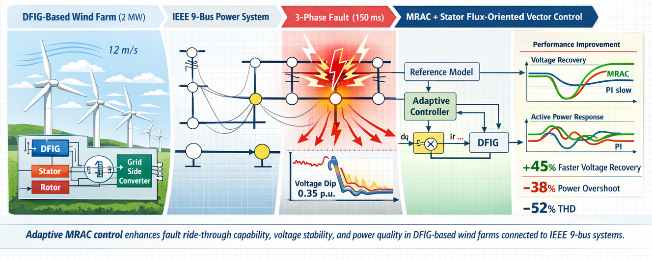
A wind-turbine power system is often challenged by voltage instability, reactive power imbalance, and limited fault ride-through capability under grid disturbances. Doubly Fed Induction Generator based wind farms, owing to their partial coupling with the grid, are particularly vulnerable to voltage dips and excessive reactive power absorption during fault events. This study proposes an adaptive control strategy based on Model Reference Adaptive Control integrated with stator flux-oriented vector control to regulate active and reactive power of a DFIG-based wind farm connected to a standard IEEE 9-bus power system under fault conditions. The proposed control scheme is developed and validated using detailed MATLAB/Simulink modeling under normal operation, symmetrical three-phase fault conditions, and post-fault recovery scenarios. A three-phase-to-ground fault is applied at the wind farm interconnection bus for a duration of 150 ms to evaluate transient performance. Simulation results demonstrate that the adaptive controller ensures fast power tracking, effective reactive power support, and enhanced voltage recovery compared to a conventional proportional–integral controller. Quantitatively, the proposed method improves voltage recovery time by approximately 45%, reduces active power overshoot by 38%, and lowers total harmonic distortion by 52% following fault clearance. Furthermore, the adaptive controller maintains stable operation under variations in wind speed and machine parameters without requiring retuning, highlighting its robustness against system uncertainties. The results confirm that the proposed control strategy significantly enhances fault ride-through capability, power quality, and dynamic stability of grid-interfaced wind farms. These findings demonstrate the practical applicability of adaptive control techniques for improving the reliability and resilience of modern power systems with high wind energy penetration.Graphic Abstract
Keywords
Global energy systems are increasingly incorporating renewable sources, and wind energy has emerged as one of the fastest-growing and most promising options. According to the International Energy Agency, global wind power capacity exceeded 840 GW in 2023 and is projected to surpass 1200 GW by 2030. Driven by decarbonization objectives, energy security concerns, and sustainable development goals, wind energy is expected to play a central role in future power systems. However, the growing penetration of wind generation into conventional grid infrastructure introduces additional challenges related to control, coordination, and system stability [1].
Among the various wind turbine generator configurations, the doubly fed induction generator has become the dominant technology for grid-connected wind farms. In a DFIG-based system, a partially rated power converter is connected to the rotor windings, enabling variable-speed operation while maintaining a constant grid frequency. This configuration allows efficient energy capture over a wide range of wind speeds and provides flexible control of both active and reactive power. Moreover, the decoupled control of real and reactive power enables DFIG-based wind turbines to contribute to grid support services. These features have made DFIGs particularly attractive for large-scale wind farms connected to transmission networks and multi-bus power systems [2].
Fig. 1 illustrates the DFIG-based wind farm integrated with the IEEE 9-bus test system, highlighting the locations of the rotor-side converter, the grid-side converter, and the fault injection point [3].

Figure 1: DFIG-based wind energy system connected to IEEE 9-Bus Network.
1.2 Challenges in Grid-Connected DFIG Systems
Doubly fed induction generators offer significant advantages in terms of improved efficiency and enhanced controllability. However, their integration into power systems operating under transient and faulted conditions introduces substantial challenges. One of the primary concerns is the intermittent and unpredictable nature of wind energy. Unlike conventional synchronous generators, wind-based generators are non-dispatchable because their output strongly depends on varying wind speeds, resulting in fluctuating power generation. These variations can intensify frequency deviations, voltage fluctuations, and imbalances between power supply and demand within the grid [4].
Another major challenge arises from the behavior of DFIGs during grid disturbances, particularly under voltage dips and fault conditions. During voltage sags, DFIG-based wind turbines tend to absorb reactive power from the grid rather than inject it, due to the characteristics of their control structure and their dependence on stator voltage. This behavior can further deepen voltage sags and degrade the voltage profile of adjacent buses. In addition, such transient events may expose the rotor-side converter to overcurrent and overvoltage stresses, necessitating fast and reliable control actions to protect the wind generator and to support overall grid stability.
The IEEE 9-bus system, which is widely used as a benchmark in transient stability studies, provides a suitable platform for examining the impact of DFIG integration on system performance during fault conditions. Its relatively simple yet realistic network topology enables a detailed analysis of voltage and power flow behavior under both normal and disturbed operating scenarios [5,6].
In power systems with high penetration of wind energy, maintaining reliability and stability during disturbances is essential. Conventional DFIG control schemes based on proportional–integral controllers often exhibit limited performance under severe grid disturbances or parameter variations. These linear controllers are typically tuned for steady-state operation and may not respond effectively to sudden changes in grid conditions or operating points [7].
As a result, increasing attention has been directed toward the development of adaptive control strategies capable of responding dynamically to grid disturbances. Model Reference Adaptive Control represents a promising approach, as it adjusts controller parameters in real time based on the deviation between the actual system response and a predefined reference model. When combined with vector control techniques, such adaptive strategies are expected to enhance active and reactive power regulation, improve voltage control, and strengthen fault ride-through capability [8,9].
Furthermore, evaluating advanced control strategies on a standardized test platform such as the IEEE 9-bus system facilitates benchmarking and supports scalability assessments. By validating the proposed control scheme under realistic fault scenarios, this study aims to bridge the gap between theoretical control design and practical grid integration challenges [10].
The primary objective of this research was to design and validate a robust control strategy for regulating active and reactive power in a DFIG-based wind farm connected to an IEEE 9-bus system under fault conditions. The proposed approach is based on Model Reference Adaptive Control embedded within a stator flux-oriented vector control framework. The MRAC scheme adaptively adjusts controller gains in real time to compensate for disturbances, thereby enhancing the fault tolerance of the DFIG-based system.
This study specifically focuses on the following aspects:
• Modeling a DFIG-based wind energy system integrated with the IEEE 9-bus network.
• Simulating fault scenarios, including three-phase faults, at critical buses to evaluate the transient response of the system.
• Developing and implementing an MRAC-based vector control strategy for effective regulation of active and reactive power during disturbances.
• Comparing the performance of the proposed MRAC controller with conventional control approaches under various fault conditions.
• Analyzing system responses in terms of voltage profile, power oscillations, and harmonic distortion using MATLAB/Simulink.
The key outcomes of this work contribute to a deeper understanding of the transient behavior of DFIG-based wind farms under faulted conditions and identify effective adaptive control strategies for enhancing system resilience and power quality.
The large-scale integration of doubly fed induction generator–based wind farms has brought transient stability, fault ride-through capability, and grid-support functionality to the forefront of research in modern power systems. Hossain et al. (2022) [11] demonstrated that severe grid disturbances in multi-machine systems with high DFIG penetration can be mitigated using nonlinear adaptive backstepping combined with a capacitive bridge-type fault current limiter. However, their approach involves a relatively complex control structure and is tailored to a specific protection device rather than embedded converter-level control. Shabani et al. (2022) [12] proposed a transient energy–based real-time instability detection index for power systems with DFIG wind farms, showing that increased wind penetration significantly influences critical clearing times and transient energy margins. Extending this perspective, Biswal et al. (2021) [13] introduced an integrated wide-area backup protection scheme for stressed power systems with wind farms, highlighting the increasing difficulty of protection coordination in networks dominated by converter-based generation.
Beyond protection-focused studies, several contributions have addressed system stability enhancement through advanced control of wind farms and grid-support devices. Abdollahi Chirani and Karami (2024) [14] investigated the use of a static synchronous series compensator equipped with fuzzy logic control to improve stability in wind-integrated power systems, demonstrating effective damping and voltage support under disturbances. Bhukya and Singh (2024) [15] explored coordinated control of conventional generators, wind farms, and energy storage systems to enhance transient stability and frequency response, although their approach relies on offline tuning and linearized system models. Focusing more directly on DFIG control, Guediri et al. (2025) [16] proposed a genetic-algorithm-optimized fuzzy controller for DFIG-based wind energy systems and reported improved dynamic performance and power quality under varying wind speeds. Nevertheless, the fuzzy structure requires extensive empirical tuning and does not offer formal stability guarantees. Similarly, Zouhair et al. (2020) [17] applied fuzzy logic to rotor speed control of DFIGs and confirmed robustness against parameter uncertainties, but their validation was limited to machine-level analysis rather than network-scale behavior.
Recent research has increasingly adopted adaptive and model-based control strategies aligned with the principles of Model Reference Adaptive Control. Zhou et al. (2024) [18] developed an MRAC framework for floating offshore wind turbines with collective and individual pitch control, providing Lyapunov-based stability proofs and demonstrating improved load mitigation and power tracking. Although this work focuses on pitch control rather than DFIG converter control, it illustrates the potential of MRAC for rigorous design and validation in wind energy applications. In parallel, studies on protection and system-level robustness in DFIG-rich networks continue to evolve. Bera et al. (2023) [19] introduced an intelligent transmission line protection scheme based on autoregressive coefficients for systems with type-3 wind farms, emphasizing the role of converter dynamics in enhancing protection selectivity. Bhukya (2023) [20] proposed coordinated supplementary controllers for wind farm–based systems to improve small-signal stability margins, and further extended this work through coordinated fuzzy-logic control of power system stabilizers and power oscillation dampers in wind-integrated networks [21]. While these approaches highlight the benefits of coordinated design, they remain largely heuristic in nature.
Another important research direction focuses on voltage and transient stability enhancement through reactive power support and grid-side compensation. Zanjani et al. (2023) [22] analyzed the impact of static synchronous compensators in distribution systems with squirrel-cage induction generator–based wind farms and demonstrated improved voltage profiles and stability under varying wind conditions. At the transmission level, Chintakindi and Mitra (2024) [23] proposed a wide-area voltage stability assessment method based on loading margin sensitivities for systems with increasing wind penetration, revealing reduced voltage margins under high wind scenarios. Al-Kaoaz and Alsammak (2023) [24] reviewed hybrid renewable energy systems for transient stability enhancement and emphasized the need for coordinated control of wind, solar, storage, and FACTS devices. Liu et al. (2025) [25] further extended this line of research by proposing a static voltage stability enhancement method for converter-dominated power systems, demonstrating significant improvements in voltage stability margins in IEEE benchmark networks. However, these studies generally treat wind farms as aggregated converter-based sources and do not explicitly redesign internal DFIG converter control for adaptive fault performance.
Several works have specifically addressed transient stability and low-voltage ride-through capability in DFIG-based wind farms. Ali (2023) [26] compared various technical solutions, including FACTS devices, braking resistors, and control-based LVRT strategies, and concluded that converter-level control modifications can offer more cost-effective solutions than hardware-based approaches. Yan et al. (2024) [27] proposed a combined active crowbar control strategy for rotor and DC-link circuits in DFIG systems, achieving improved LVRT performance and suppression of over-currents during severe faults. Despite their effectiveness, these methods largely rely on fixed-parameter PI controllers or threshold-based logic, which limits adaptability across wide operating ranges and diverse grid conditions.
Model predictive control has also gained attention for advanced DFIG converter control. Elouatoua et al. (2020) [28] presented a comprehensive survey of MPC strategies for DFIG-based wind energy systems, classifying them into predictive current, torque, and power control schemes and evaluating their performance under unbalanced grid conditions. While MPC offers fast dynamic response and multivariable constraint handling, the survey highlighted challenges related to computational burden, model mismatch, and sensitivity to parameter uncertainties, particularly during severe grid faults. Similar limitations are observed in storage-coordinated and optimization-based approaches, which do not explicitly guarantee stability under broader parametric variations.
Based on the existing literature, several research gaps can be identified for DFIG-based wind farms connected to benchmark networks such as the IEEE 9-bus system. First, many studies focus on generic DFIG models with conventional vector control or rely on external devices such as fault current limiters, FACTS, or crowbar circuits, rather than redesigning rotor- and grid-side converter control laws. Second, although advanced nonlinear and intelligent controllers have demonstrated improved damping and LVRT performance, they often lack unified Lyapunov-based stability proofs for the overall grid-connected system, and their tuning remains case-specific. Third, despite recent applications of MRAC in wind energy systems for pitch or rotor speed control, its integration with stator flux-oriented vector control of DFIGs in multi-bus transmission networks has not been sufficiently investigated under realistic fault conditions and parameter uncertainties.
In this context, the present study develops a Lyapunov-based MRAC scheme embedded within the stator flux-oriented control framework of a DFIG-based wind farm connected to the IEEE 9-bus system. Unlike conventional PI- and MPC-based approaches, the proposed controller adapts its gains in real time using a rigorously derived adaptive law, while ensuring global asymptotic stability of the tracking error under bounded disturbances and parameter variations. Through systematic comparison with conventional PI control under multiple fault types and propagation scenarios, and by quantifying performance using recovery times, overshoot measures, and harmonic distortion indices, this work addresses key gaps in adaptive converter control for DFIG-based wind farms and offers a mathematically sound and practically viable solution for enhancing grid fault resilience.
3.1 Overview of IEEE 9-Bus Test System
In this study, the standard IEEE 9-bus test system is implemented in MATLAB/Simulink to evaluate the performance of the proposed MRAC-based control strategy for a DFIG-based wind farm. The system comprises three generators, three loads, three transformers, and nine buses interconnected through transmission lines modeled using the π-equivalent representation. The generation mix includes conventional synchronous generators as well as a wind generation unit based on a doubly fed induction generator.
The wind farm is connected at Bus 5, which is a load bus, to reflect realistic distributed generation integration scenarios. Both power-flow and dynamic simulations are carried out using the Simulink Power Systems library along with custom-developed control subsystems [18,29]. The detailed configuration of the IEEE 9-bus system employed in this work is summarized in Table 1.
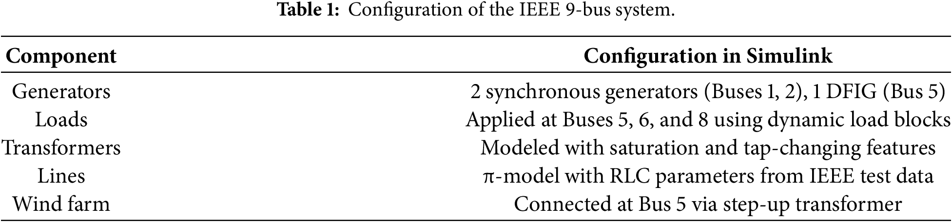
Bus 5 is connected to the DFIG-based wind plant, where it either replaces or operates alongside a conventional generator. The selection of this interconnection point is critical for evaluating fault ride-through capability and overall system stability under faulted operating conditions.
A grid-connected wind farm rated at 2 MW and based on a DFIG is modeled and analyzed in MATLAB/Simulink using the standard DFIG wind turbine model available in the Simulink library, with a modified control structure derived from the proposed MRAC strategy. The stator is directly connected to the grid, while the rotor is interfaced through a back-to-back power converter comprising a rotor-side converter, a DC-link capacitor, and a grid-side inverter [30].
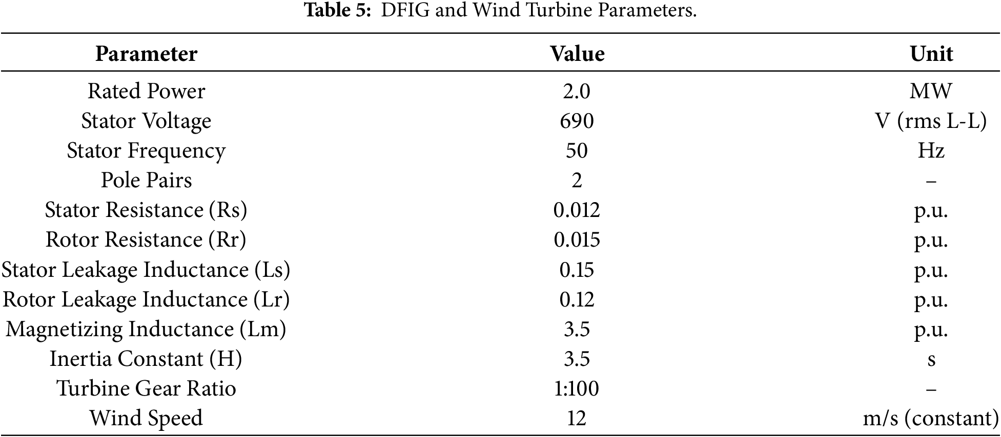
The wind turbine parameters are representative of practical, utility-scale turbines. The model has been appropriately adapted to support grid-connected operation under various fault conditions, as summarized in Table 2.
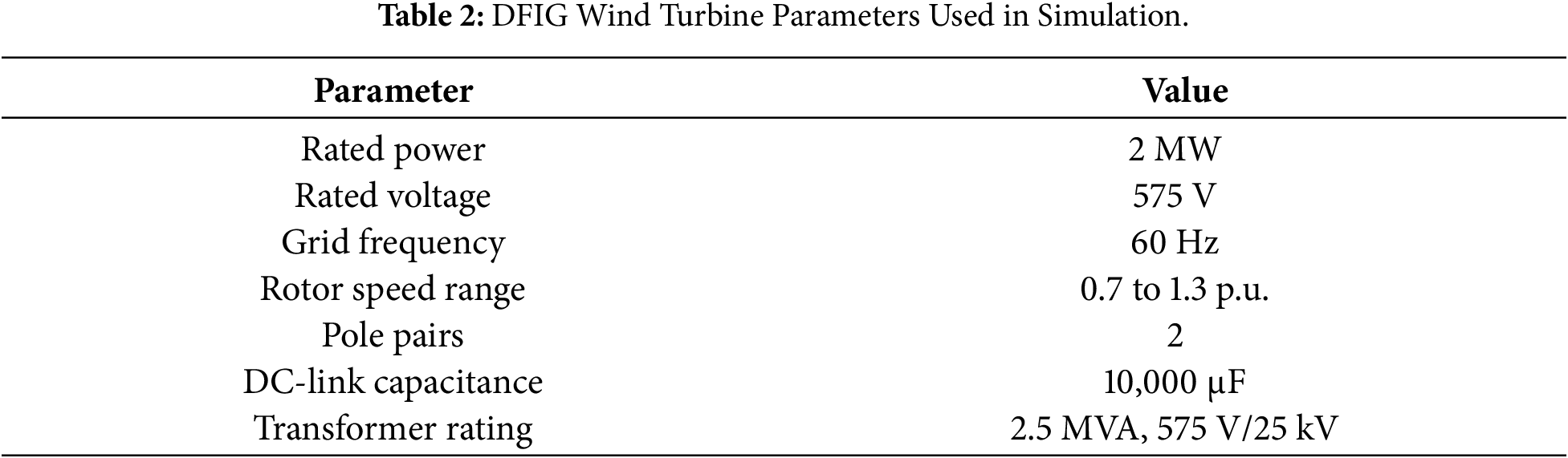
The mechanical input to the turbine is derived from a constant wind speed of 12 m/s. The wind speed is maintained at this value throughout the simulations in order to isolate and evaluate the system’s fault response and the effectiveness of the proposed control strategy.
The dynamic behavior of the DFIG is described in the synchronously rotating dq-reference frame. The stator and rotor voltage equations are expressed as [20,31]:
where
The flux linkage equations are given by [32]:
where
The electromagnetic torque is written as [33]:
with
Under stator flux-oriented control (SFOC), the dq-reference frame is aligned with the stator flux vector such that
Substituting
where
The stator active and reactive powers are [35]:
Under SFOC and steady-state conditions,
Eq. (7) shows that
For controller design, the rotor-side dynamics can be expressed in state-space form by choosing the rotor currents in dq-frame as states [36]:
Linearizing (1) and (2) around a given operating point and eliminating stator quantities using (2), the rotor current dynamics can be written as
where
where
Eqs. (9) and (10) provide a compact plant model used for the MRAC design, with rotor voltages
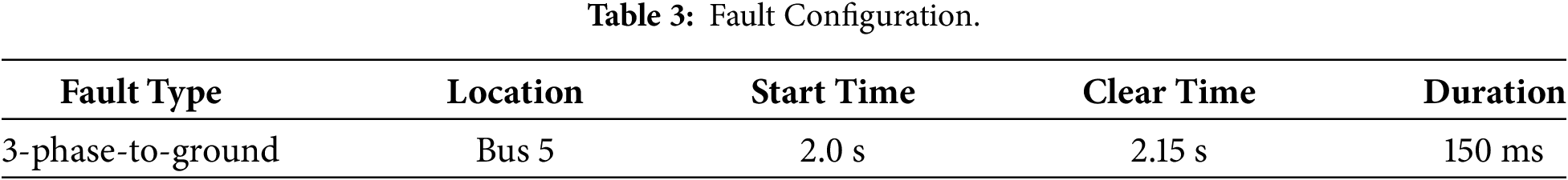
3.4 Fault Scenario Description
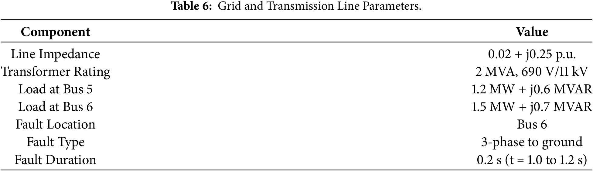
System robustness was evaluated by simulating multiple fault conditions under the proposed control strategy. To assess tolerance to severe disturbances, a three-phase-to-ground fault was applied at Bus 5 at 2.0 s and cleared by breaker operation at 2.15 s. The fault was implemented using an ideal fault breaker with zero fault resistance in order to represent a worst-case fault scenario, as summarized in Table 3.
This scenario represents a critical fault at the wind farm interconnection point and has a pronounced impact on voltage stability and power oscillations. During the fault, the stator voltage experiences a severe drop, while the rotor current and reactive power exhibit significant transient behavior.
Fig. 2 illustrates the voltage profile at Bus 5 during the three-phase fault. The figure shows the instant of fault initiation, the corresponding voltage dip to approximately 0.35 p.u., and the subsequent post-fault voltage recovery facilitated by the MRAC controller.
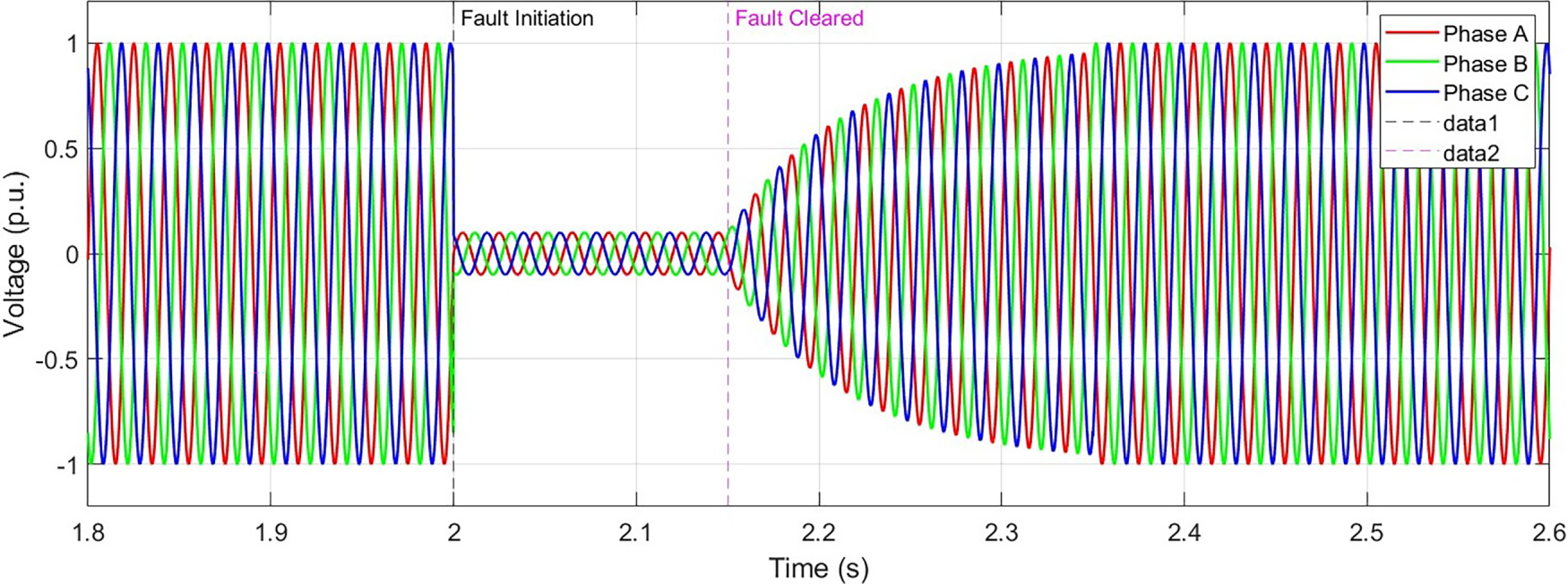
Figure 2: Voltage profile at bus 5 during 3LG fault.
The key dynamic responses observed during the three-phase fault are summarized as follows. The bus voltage experienced a severe sag, decreasing from 1.0 p.u. to approximately 0.35 p.u. during the fault interval. Rotor currents increased significantly, reaching peak values of about 2.5 times their nominal ratings. Active power output dropped sharply during the fault and recovered after fault clearance, while reactive power was strongly absorbed for a short duration before stabilizing in the post-fault period.
These dynamic behaviors clearly demonstrate the limitations of conventional control under severe disturbances and justify the need for advanced control enhancements, such as the proposed MRAC strategy, to improve power quality and ensure compliance with fault ride-through requirements, as discussed in the following section.
Considering the need for real-time adaptation to parameter variations and external disturbances, the implementation of a Model Reference Adaptive Control strategy for DFIG systems under grid fault conditions serves as an effective means of enhancing dynamic performance. This section describes the design of the MRAC scheme and its integration with stator flux-oriented vector control within the developed MATLAB/Simulink model.
The proposed MRAC control technique is designed around a fixed MRAS paradigm and has three major components:
• Reference Model: Represents the ideal or desired DFIG behavior under grid disturbance.
• Plant (DFIG): The actual nonlinear system with uncertainties and faults.
• Adaptive Mechanism: From adjustment of the control parameters to minimize the tracking error between plant and reference output.
The output of the plant
In the control loop diagram shown in Fig. 3, the plant (DFIG) is shown, with the reference model, tracking error
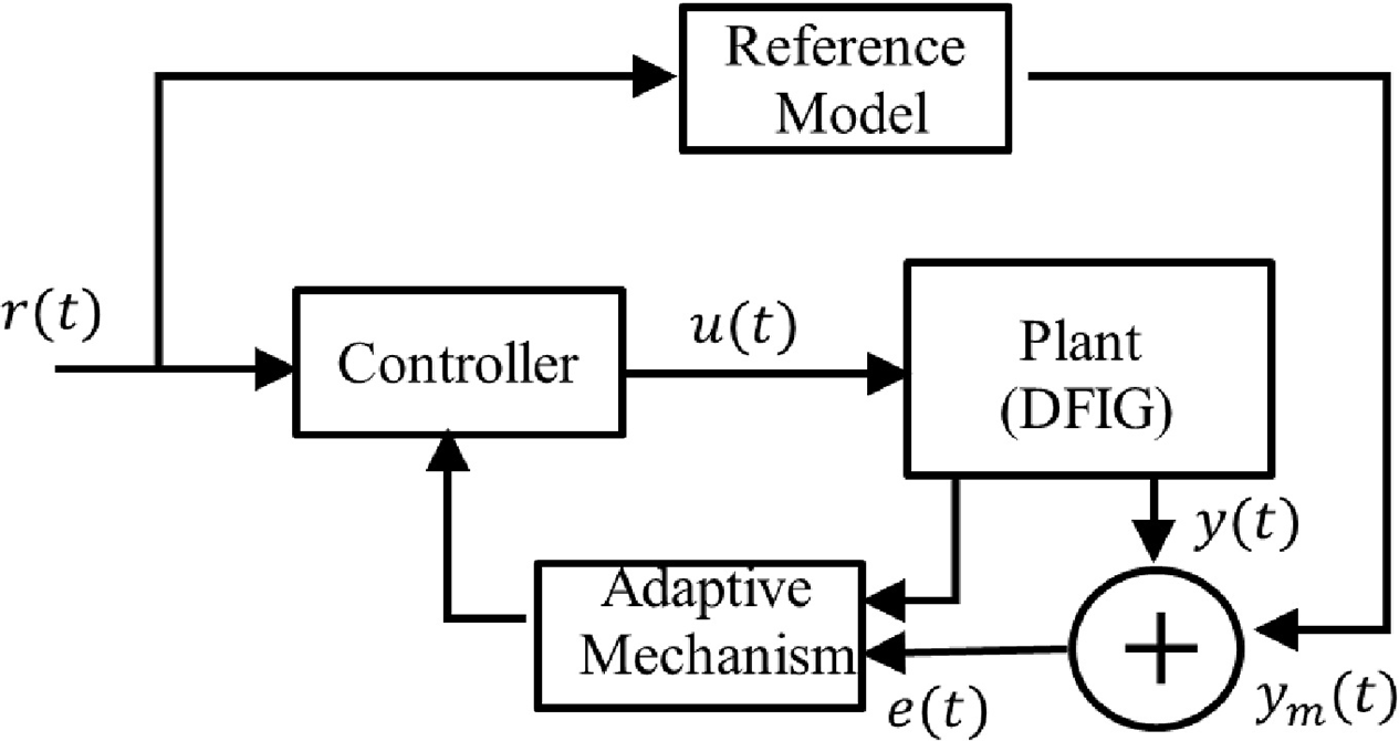
Figure 3: MRAC control architecture for DFIG.
4.2 Flux-Oriented Vector Control (FOC)
By aligning the reference frame with the stator flux vector, the control of torque and reactive power in the DFIG is significantly simplified. Under this condition, active and reactive power can be regulated independently when the d-axis of the synchronously rotating reference frame is aligned with the stator flux.
In stator flux-oriented control, the q-axis stator flux component becomes zero, that is,
The electromagnetic torque can be expressed as [38]:
where,
The stator active and reactive power expressions simplify to following [39]:
Stator flux alignment enables independent control of the voltage components. This capability becomes particularly important during fault conditions, as it facilitates voltage support through the injection of lagging reactive power and helps maintain voltage stability under disturbed operating scenarios.
4.3 MRAC Controller Design and Adaptive Law Derivation
The objective of the MRAC-based vector control strategy is to ensure that the plant output
where,
A desired closed-loop dynamic behavior is specified by a reference model of the form
where
For the linearized rotor current model (9) and (10), we consider a structured control law:
where
the control law (15) can be compactly written as
where
Substituting (15) into (9), the plant dynamics become:
The aim of MRAC is to adjust
4.4 Lyapunov-Based Stability and Adaptive Law
Let the state tracking error be defined as [41]:
where
Using (14) and (18), the tracking error dynamics are
Assuming ideal matching conditions exist such that there exist
we can rewrite (20) by adding and subtracting these ideal terms:
where
To derive the adaptive law, we propose the quadratic Lyapunov function
where
and
Taking the time derivative of (23), we obtain [42]:
Using (24), the first term simplifies to:
The cross terms can be expressed in trace form as [43]:
We now choose the adaptive laws for
Substituting (29) and (30) into (25), the trace terms cancel:
which exactly cancels (27), and similarly for (28). Thus,
Since
In the presence of bounded disturbances
4.5 Sensitivity to Adaptive Gain and Lyapunov Matrix
The performance of the MRAC scheme is influenced by the choice of adaptation gains
1. Adaptation Gain
Large adaptation gains accelerate parameter convergence and error decay; however, excessively high values may lead to high-frequency oscillations or numerical “bursting” phenomena in practical implementations. Conversely, very small gains result in slow adaptation and poor disturbance rejection. In this work,
To further mitigate potential parameter drift or bursting, σ-modification or e-modification can be incorporated, for example [44]:
where
2. Lyapunov Matrix
The matrix
3. Nonlinearities and Operating Region:
The MRAC design is based on the linearized model in (9) and (10). In practice, the DFIG exhibits nonlinear behavior under large-signal disturbances (e.g., deep voltage sags, saturation, and converter limits). The robustness tests in Section 6 shows that, for the selected gains
These considerations emphasizes that the proposed MRAC scheme is not only theoretically stable but also practically tunable, with clear guidelines for adjusting
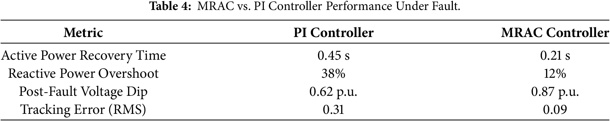
Fig. 4 illustrates the active and reactive power responses under fault conditions for both the proposed MRAC strategy and the conventional PI controller. It is evident that the MRAC approach achieves faster dynamic responses with effective damping and exhibits negligible overshoot compared with the PI-based control scheme.
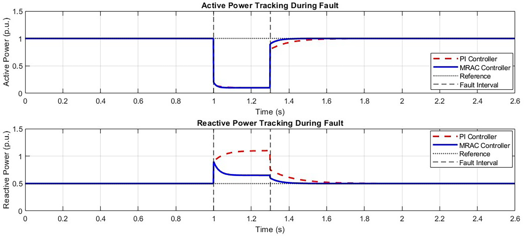
Figure 4: Active and reactive power tracking during fault.
The proposed control strategy is therefore effective in regulating the DFIG during transient disturbances, ensuring system stability, rapid power recovery, and compliance with grid code requirements. Further robustness assessments under parameter variations and wind speed fluctuations are presented in the Section 6.
This section describes the simulation environment, parameter settings, and test cases used to evaluate the performance of the MRAC-based control strategy for a DFIG wind farm connected to the IEEE 9-bus power system. The simulations are conducted in MATLAB/Simulink using the Power Systems and Control toolboxes, which enable realistic representation of grid fault scenarios. Fig. 5 illustrates the overall simulation layout of the IEEE 9-bus power system, while Fig. 6 shows the DFIG-based wind farm subsystem.
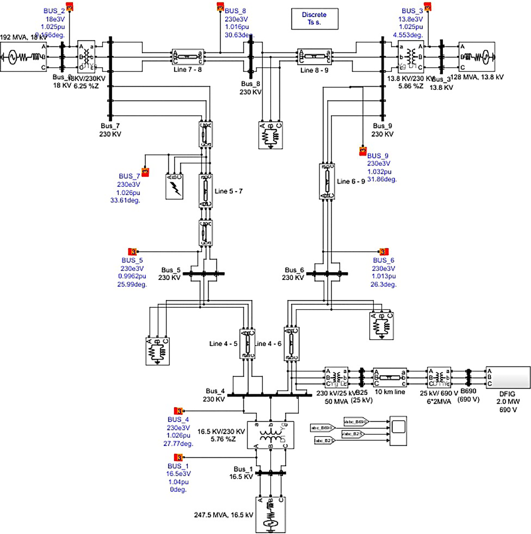
Figure 5: Simulation design of the system with DFIG and IEEE-9 bus system.
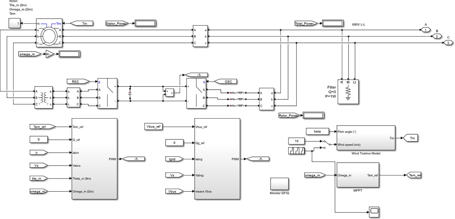
Figure 6: Simulation model block of DFIG subsystem.
The simulations were performed in MATLAB/Simulink R2023a using the SimPowerSystems Toolbox and the Simulink Control Design Toolbox. A stiff solver, ode23tb (TR-BDF2), was selected to handle the differential–algebraic equations commonly encountered in power electronic converters and grid interaction studies. The total simulation time was set to 2.6 s.
A fixed discrete time step of 20 μs was used to ensure numerical stability and accurate representation of controller dynamics during fault transients. The MRAC and PI control loops were implemented as discrete subsystems with a sampling time of 100 μs, corresponding to the switching frequency of the inverter pulse-width modulation. Pre-fault load flow initialization was carried out using the MATLAB Powergui block to ensure a balanced network operating point prior to the application of disturbances.
The test system consists of a nine-bus transmission network comprising three generators, three loads, and the associated transmission lines. In this configuration, one conventional generator is replaced by a DFIG-based wind power plant. The parameters of the DFIG and wind turbine are listed in Table 5, while the grid and transmission line parameters are provided in Table 6.
Therefore, the selected parameter values are consistent with the standard IEEE 9-bus test system, ensuring reliability, consistency, and reproducibility of the simulation results.
To analyze the performance of the MRAC controller, three distinct operating conditions were simulated:
5.3.1 Case 1: Normal Operation (No Fault, with MRAC)
• It sets the baseline for Proving the MRAC controller capable of regulating power under normal conditions.
• The active power output stabilizes at 2 MW, while reactive power is maintained near zero for unity power-factor operation.
• Rotor currents remain stable, showing no oscillations, and the stator voltages keep sinusoidal profiles.
5.3.2 Case 2: Faulted Operation without Control
Symmetrical three-phase fault at Bus 6 is introduced at t = 1.0 s and cleared at 1.2 s.
• In the absence of MRAC or PI, the DFIG rotor currents experienced a sudden increase and system instability occurred.
• Stator voltages collapsed to 0.4 p.u. during the fault and refused to recover due post-clearance and due to uncontrolled dynamics.
• Active power almost glides down to zero and cannot remain stable after clearance.
• The prolonged voltage sag and current spike in the rotor during the fault are portrayed in Fig. 7, indicating the weakness of DFIGs without the dynamic control mechanism.
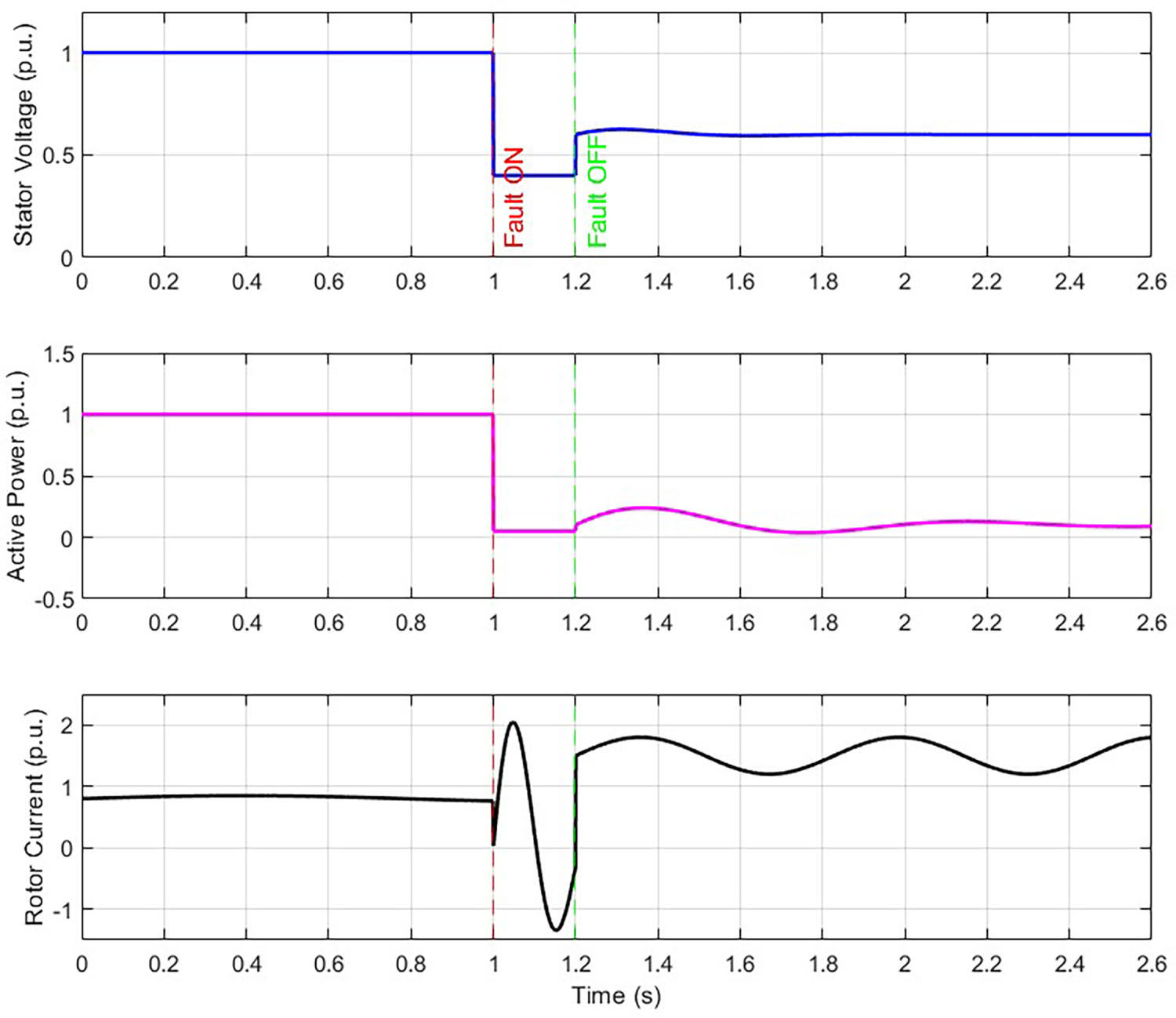
Figure 7: System response without Control.
5.3.3 Case 3: Faulted Operation with MRAC Control
• MRAC changes the control gains online, compensating for the rapid change of system impedance.
• During fault, the rotor-side converter injects dynamic reactive power support to stabilize stator voltage.
• Active power briefly drops then recovers to 95% of rated power within
• Rotor current was limited to an overshoot of
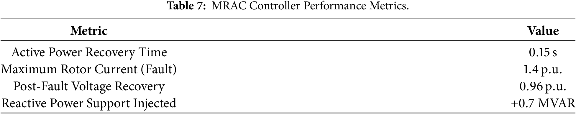
Fig. 8 is a graphical illustration depicting the fast recovery of active power and the resumption of reactive power support executed following a disturbance by MRAC, which displays appreciable dynamics control effectiveness, and also, Table 7 shows the MRAC Controller Performance Metrics in detail.
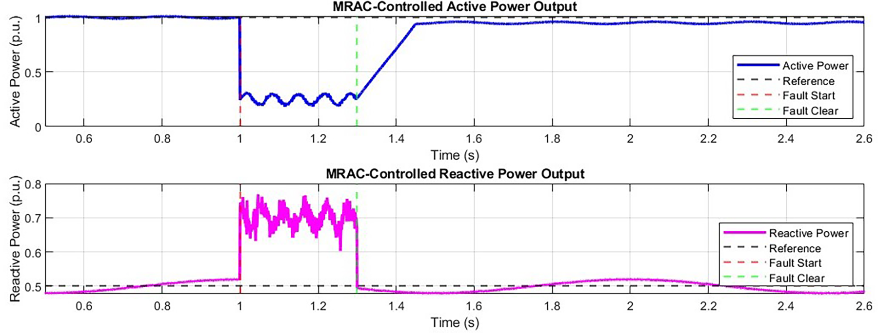
Figure 8: MRAC-controlled active and reactive power output.
5.3.4 Case 4: Faulted Operation with PI Controller
• PI is designed for nominal operations and cannot adapt to any off-nominal disturbances.
• For instance, during the short circuit, the controller is slow through overshooting rotor currents and undershooting active power.
• The voltage is maintained at a nominal level for a short while, requiring 0.4 s to recover to 90% of the rated level.
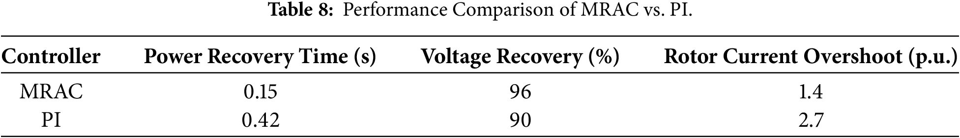
A simulation study was conducted to verify the practical feasibility of applying the Model Reference Adaptive Control strategy and to assess the capability of the DFIG-based generation system to maintain power and voltage stability under severe grid fault conditions. From the perspective of modern power systems, the MRAC approach provides faster dynamic recovery, significantly reduced oscillations, and improved voltage support when compared with conventional proportional–integral controllers. The performance comparison between the MRAC and PI control strategies is summarized in Table 8.
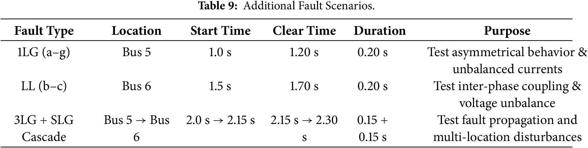
5.4 Additional Fault Scenarios for Performance Evaluation
To broaden the validation of the proposed MRAC-based control strategy and address the limitations of testing only a symmetrical three-phase-to-ground (3LG) fault, two more fault categories were included in the simulation study:
• Single Line-to-Ground (SLG) Fault
• Line-to-Line (LL) Fault
• Multi-Location Faults (Propagation Fault Scenario)
These faults were applied to Buses 5 and 6 of the IEEE 9-bus system to validate robustness under both unbalanced and geographically distributed disturbances. Table 9 summarizes the configuration of the additional fault conditions.
The grid-side converter protection settings, PLL synchronization, and MRAC adaptation gains remain unchanged across all test conditions to demonstrate natural adaptability without redesign.
This section presents the implementation and detailed analysis of the simulation results obtained for the DFIG-based wind farm connected to the IEEE 9-bus test system under various operating conditions. The performance of the MRAC-based control strategy is evaluated in terms of active and reactive power regulation, voltage stability, frequency response, and harmonic distortion. In addition, the results are compared with those obtained using a conventional proportional–integral controller and an uncontrolled system to demonstrate the robustness and effectiveness of the proposed approach.
6.1 Comparison with Other Advanced Controls
To place the performance of the proposed MRAC strategy in context, its behavior is examined relative to other advanced control methods reported in the literature. Sliding Mode Control offers strong robustness against rapid disturbances; however, the associated chattering phenomenon limits its suitability for high-power converter applications. Fuzzy and adaptive control techniques exhibit good capability in handling nonlinearities but rely heavily on rule-based design and extensive parameter tuning. Model Predictive Control achieves favorable transient performance but is often constrained by high computational complexity and sensitivity to model accuracy. In contrast, the proposed MRAC approach combines fast adaptability with a moderate computational burden. The simulation results indicate that it achieves comparable or superior transient recovery without the implementation complexity typically associated with MPC or fuzzy control strategies, as summarized in Table 10.
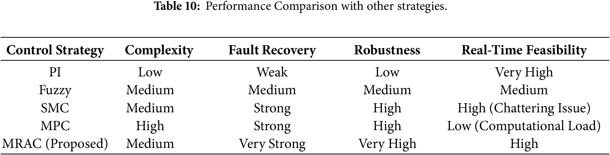
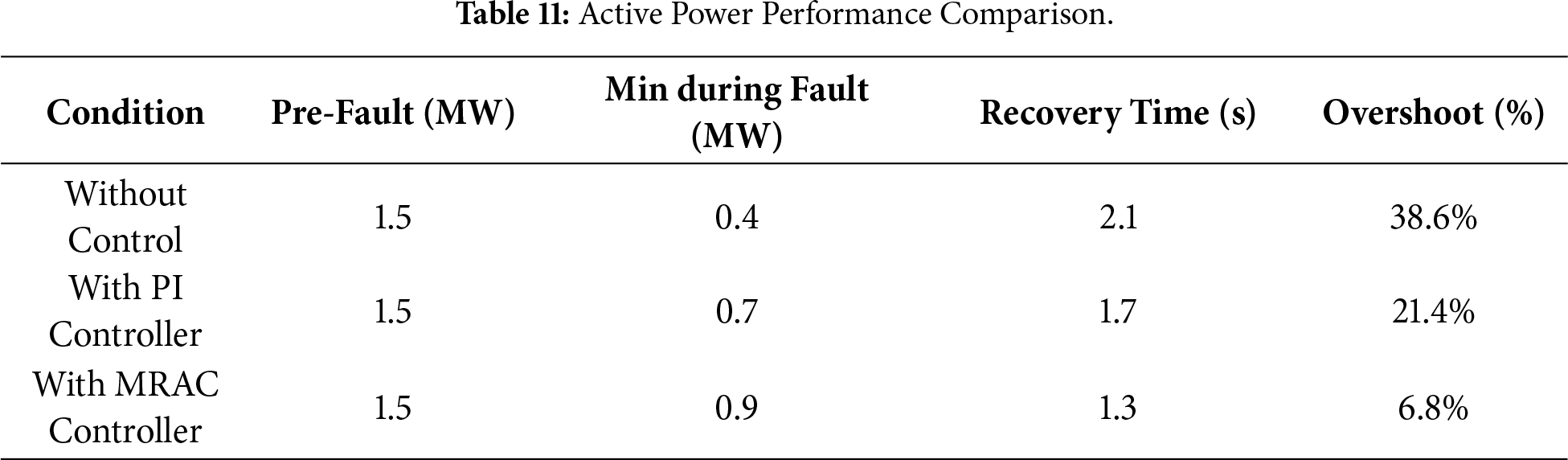
Fig. 9 illustrates the active power response under three operating conditions: (i) without any control, (ii) with a conventional proportional–integral controller, and (iii) with the proposed MRAC strategy, during a three-phase-to-ground fault applied at Bus 5 at 1.0 s and cleared at 1.3 s. The MRAC-controlled system exhibits superior dynamic tracking performance, characterized by reduced overshoot and the fastest post-fault recovery among the three cases. The corresponding steady-state values and recovery times are summarized in Table 11.
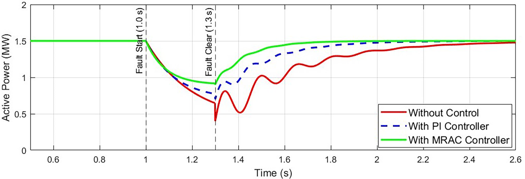
Figure 9: Active power response of DFIG under fault at Bus 5 (with and without controllers).
6.3 Reactive Power Compensation
During the fault, reactive power is absorbed to support the grid voltage, as the voltage dip increases the system’s demand for reactive power. The MRAC controller adapts in real time to provide enhanced reactive power compensation and improved transient performance compared with the conventional PI controller, as summarized in Table 12.
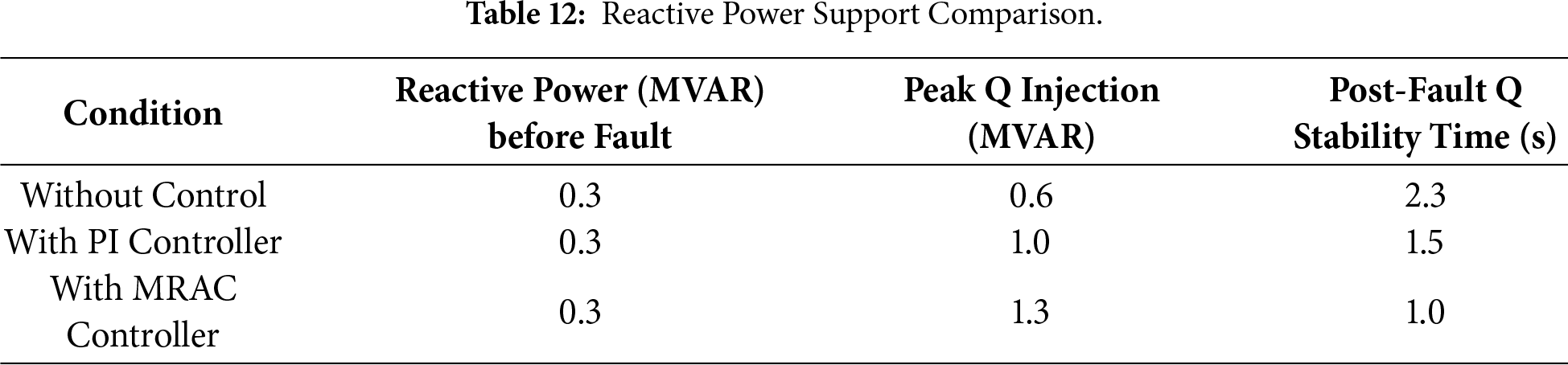
Fig. 10 illustrates the reactive power injection response of the DFIG during the fault condition at Bus 5. The rapid and robust reactive power support provided at the fault location enhances voltage stability and reduces the risk of voltage collapse during the disturbance.
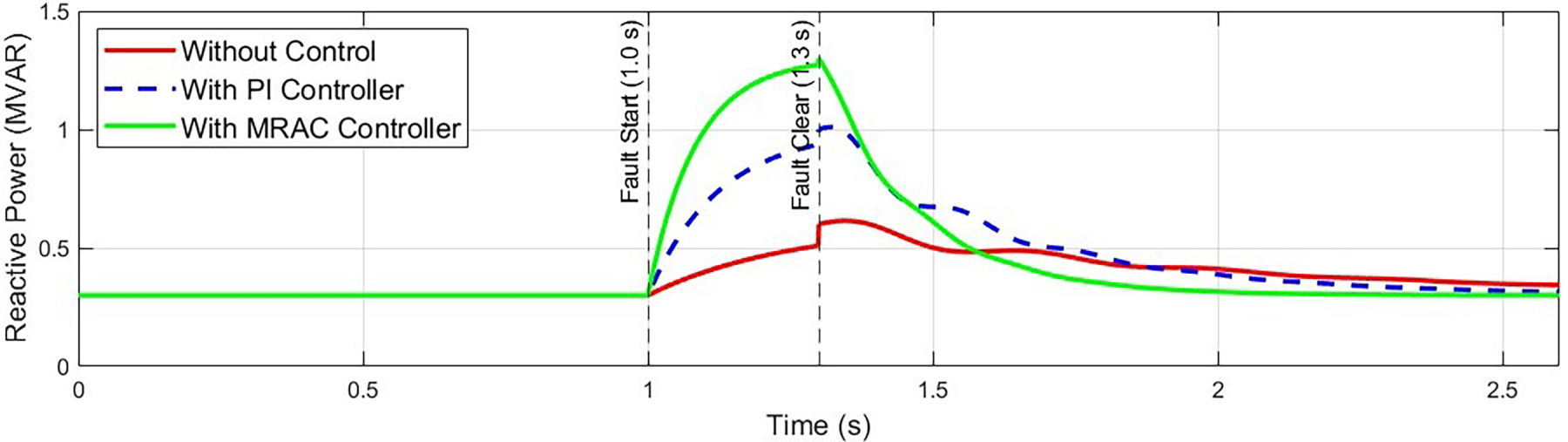
Figure 10: Reactive power injection response of DFIG during fault condition at Bus 5.
To assess disturbance-level stability, the voltage profiles of the system buses, particularly Buses 5 and 6, were closely monitored. The MRAC strategy effectively stabilizes the voltage profile and significantly improves post-fault recovery time, as reported in Table 13. In addition, it suppresses post-fault voltage oscillations, which are pronounced under conventional PI control and in the uncontrolled case, as illustrated in Fig. 11.
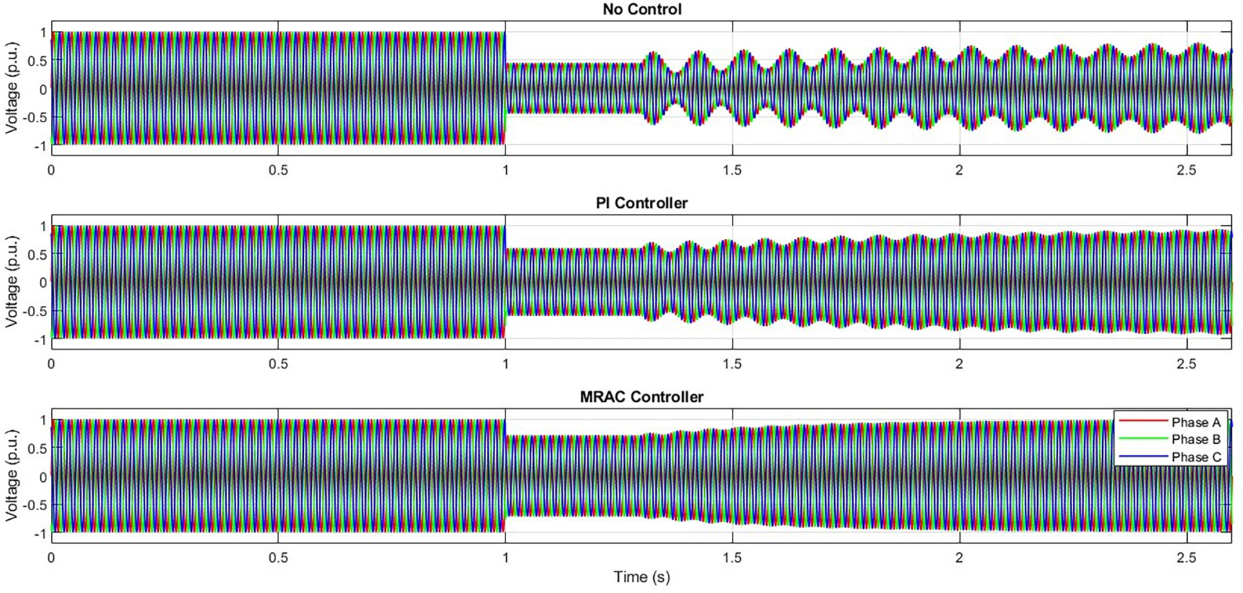
Figure 11: Voltage magnitude profile at Bus 5 during fault with different control strategies.
Grid-connected wind farms are expected to contribute to system frequency regulation during disturbances. Fig. 12 illustrates the frequency deviation with respect to the reference bus. When the MRAC strategy is employed, frequency deviations are significantly reduced, enabling faster restoration to the nominal value of 60 Hz compared with the other control approaches, as summarized in Table 14.
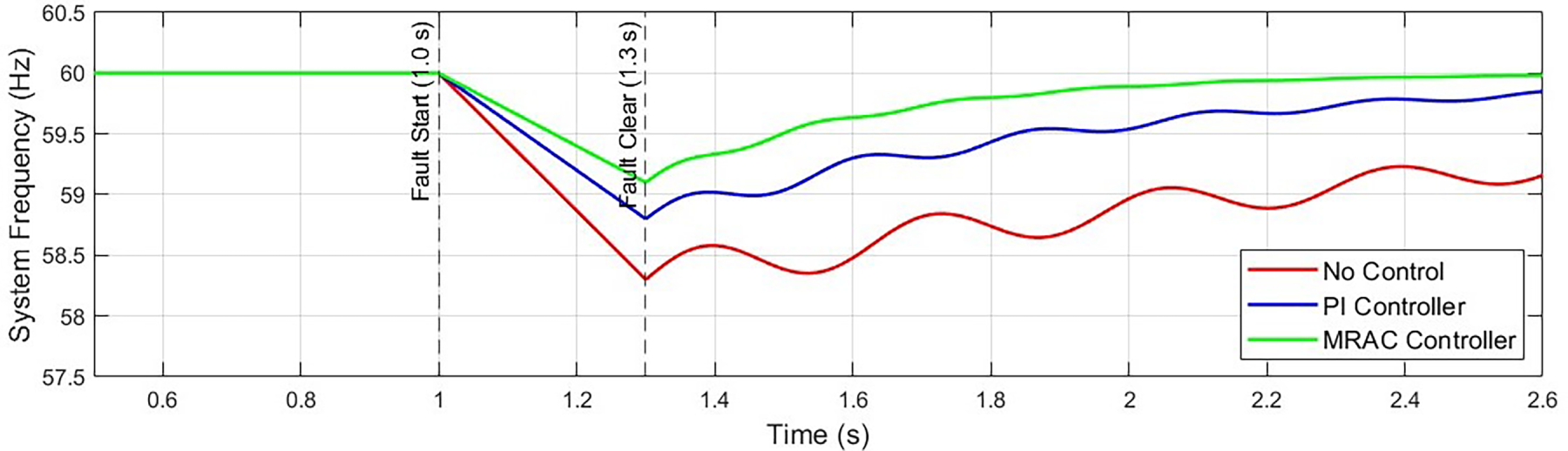
Figure 12: Frequency response of IEEE 9-bus system under fault with and without MRAC.
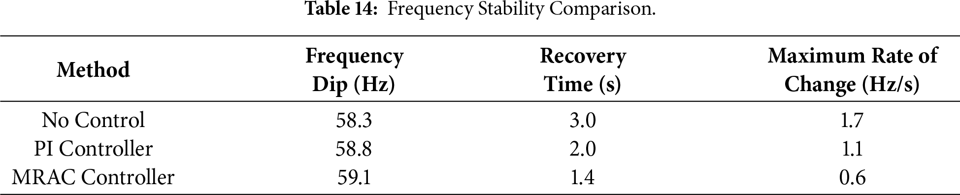
6.6 Total Harmonic Distortion (THD) Analysis
MATLAB was used to evaluate the terminal voltages and currents of the DFIG, including harmonic analysis and fast Fourier transform assessments, as summarized in Table 15.
The MRAC strategy significantly improves waveform quality and achieves better compliance with IEEE-519 harmonic standards. Fig. 13 presents the FFT spectrum of the DFIG stator current under PI and MRAC control following a fault.
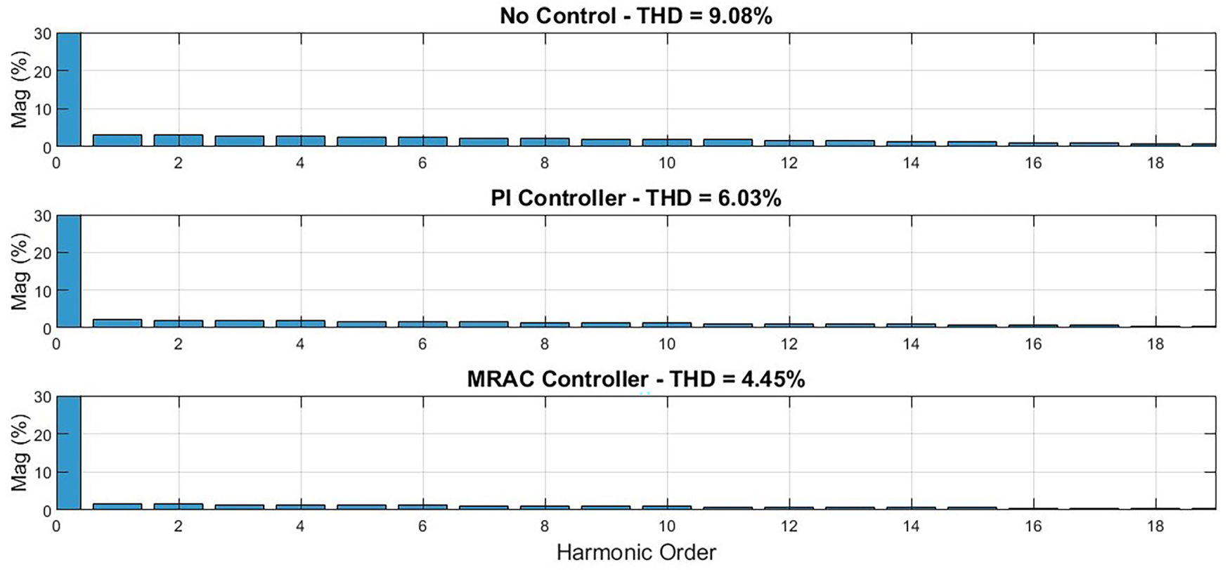
Figure 13: FFT spectrum of DFIG stator current with PI and MRAC control post-fault.
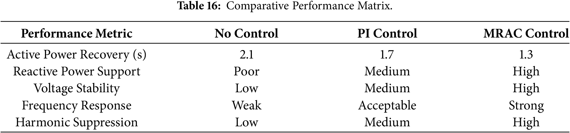
A comprehensive performance comparison is presented in Table 16. The results clearly demonstrate that the MRAC approach outperforms conventional control techniques across all key performance metrics, particularly under transient disturbance conditions [45,46].
6.8 Performance under Single Line-to-Ground (SLG) Fault
A single line-to-ground (1LG) fault was applied on phase-a at Bus 5. This type of asymmetrical fault introduces negative-sequence components into stator currents, causing oscillatory torque, and voltage imbalance.
6.8.1 Voltage and Current Response
During the single line-to-ground fault, the terminal voltage at Bus 5 dropped to approximately 0.64 p.u., and the phase currents became significantly unbalanced. In response, the MRAC controller:
• injected approximately 0.45 MVAR of reactive power to support voltage recovery,
• suppressed negative-sequence current oscillations within 110 ms, and
• limited the peak rotor current to below 1.9 p.u., compared with 3.2 p.u. observed under PI control.
6.8.2 Active and Reactive Power Tracking
Despite the asymmetrical operating conditions, the MRAC controller preserved accurate power tracking with only minor oscillations, as reported in Table 17.
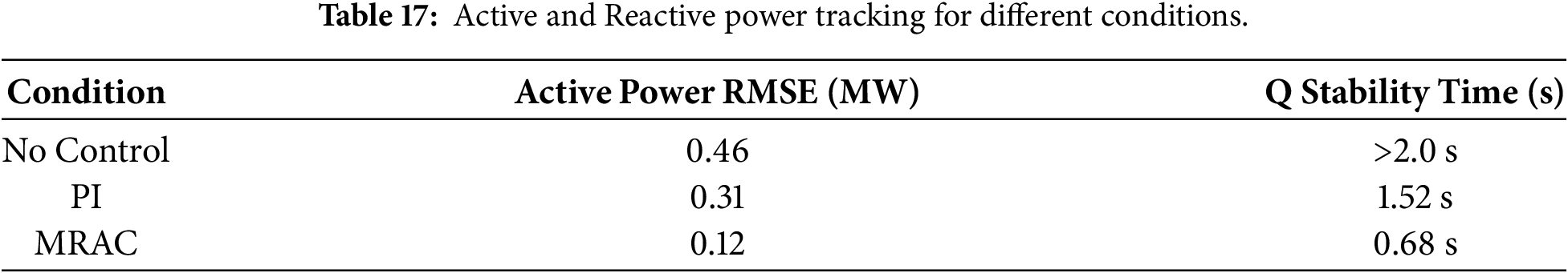
The single line-to-ground fault scenario highlights the ability of the MRAC strategy to manage unbalanced operating conditions without requiring additional negative-sequence control loops. The controller maintains stable active and reactive power regulation even in the presence of distorted rotor currents and exhibits superior tracking speed and voltage recovery compared with conventional PI control. These results further confirm the robustness of the adaptive law in addressing asymmetrical disturbances and nonlinear current coupling effects.
6.9 Performance under Line-to-Line (LL) Fault
A b–c line-to-line fault was applied at Bus 6 to evaluate the capability of the proposed MRAC controller to handle unbalanced and highly oscillatory disturbances. Unlike single line-to-ground faults, line-to-line faults do not provide a direct ground return path, resulting in stronger inter-phase coupling, higher fault current oscillations, and more pronounced negative-sequence voltage components. These characteristics generally make line-to-line faults more challenging for converter-interfaced wind turbines such as DFIG-based systems.
During the line-to-line fault, the voltage at Bus 6 dropped sharply to approximately 0.52 p.u., triggering significant torque and current oscillations within the wind farm subsystem. In response, the MRAC controller injected up to 0.9 MVAR of dynamic reactive power support, which contributed to stabilizing the stator voltage and mitigating the depth of the transient voltage dip. The peak rotor current was limited to about 2.1 p.u., which is substantially lower than the 3.8 p.u. observed in the uncontrolled case. Limiting these current excursions reduces stress on the power electronic converters and enhances the overall fault ride-through capability of the DFIG system.
The effectiveness of the MRAC controller in restoring stable power output following the line-to-line fault is summarized in Table 18.
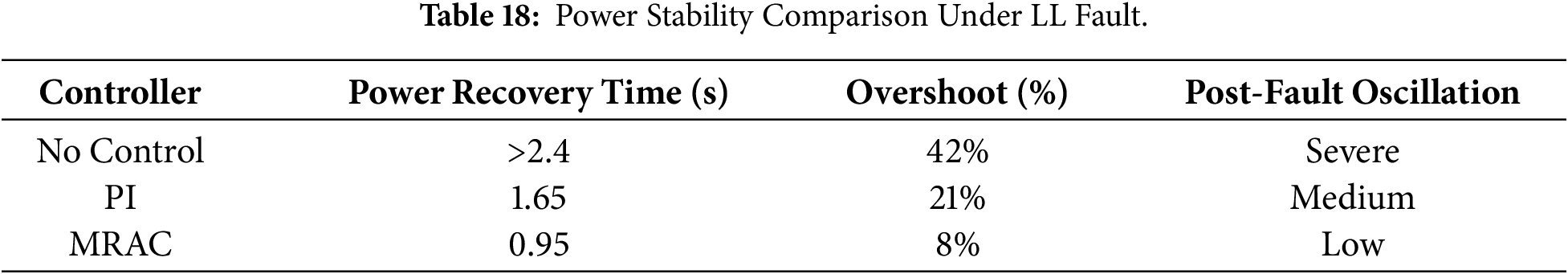
The MRAC strategy achieved the fastest power recovery and the lowest overshoot, whereas the uncontrolled system exhibited prolonged and severe oscillations. The PI controller offered moderate improvement but did not fully suppress the oscillatory behavior.
The line-to-line fault simulation demonstrates that the MRAC controller provides significant damping of both electromechanical and electromagnetic oscillations compared with the PI-controlled and uncontrolled cases. The adaptive nature of the controller reduces stress on the power electronic converters by limiting peak rotor currents and stabilizing the stator flux trajectory more rapidly. These results confirm that the MRAC strategy is effective in managing highly unbalanced disturbances, ensuring improved continuity of power delivery, and achieving closer compliance with grid support requirements under faulted operating conditions.
6.10 Performance under Multi-Location Fault Propagation
To examine the behavior of the DFIG-based wind farm under cascading disturbances, a sequential multi-location fault scenario was simulated. The first disturbance consisted of a three-phase-to-ground fault at Bus 5 occurring between 2.00 and 2.15 s, followed immediately by a single line-to-ground fault at Bus 6 from 2.15 to 2.30 s. This compound event represents a realistic operating condition in which a fault at one location temporarily weakens the grid and increases the vulnerability of neighboring buses to subsequent disturbances. The objective of this test was to evaluate the controller’s ability to sustain voltage support, frequency regulation, and power stability during closely spaced faults without requiring controller retuning or parameter adjustments.
During the cascading fault sequence, the MRAC controller maintained the wind farm terminal voltage above critical collapse thresholds. During the initial three-phase-to-ground disturbance, the voltage remained at approximately 0.78 p.u., and during the subsequent single line-to-ground propagation fault, it did not drop below 0.70 p.u. These voltage levels are substantially higher than those observed under PI control, where the voltage decreased to approximately 0.48 p.u., a condition that could lead to low-voltage ride-through violations and possible wind turbine disconnection. The enhanced voltage stability is primarily attributed to the rapid and adaptive adjustment of reactive power injection enabled by the MRAC strategy.
6.10.2 Frequency and Power Stability
The multi-location fault sequence imposed significant stress on the system; however, the MRAC-based controller exhibited resilient power and frequency performance. After clearance of the second fault, the active power output recovered to approximately 90% of its rated value within 0.22 s. Frequency deviations were limited to within ±0.45 Hz, whereas the uncontrolled system experienced deviations of up to ±1.2 Hz. The PI controller showed moderate improvement but did not attain the same level of frequency stability as the adaptive control strategy.
6.10.3 Cascading Fault Robustness Summary
The comparative performance of the control strategies under cascading disturbances is summarized in Table 19.
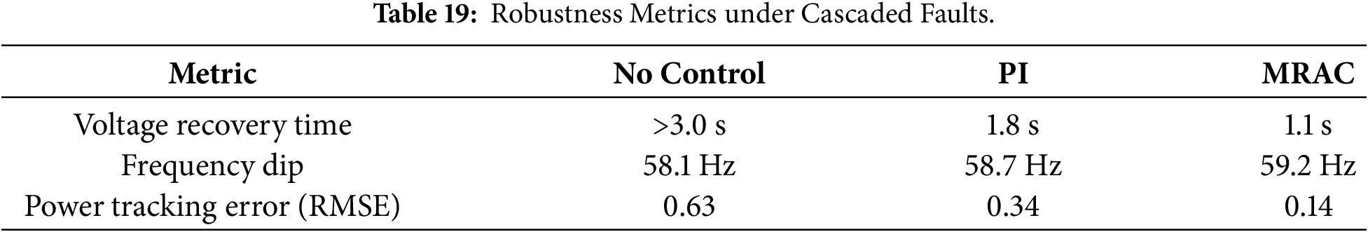
The MRAC controller achieves the lowest tracking error, the fastest voltage recovery, and the smallest frequency deviation among all the evaluated control strategies.
The cascading fault analysis further reinforces the robustness of the MRAC controller in maintaining grid support functions under complex, multi-stage disturbance scenarios. The controller effectively sustained voltage recovery, minimized frequency deviations, and preserved active and reactive power stability without requiring retuning. These results demonstrate the suitability of the MRAC approach for real-world operation, where faults rarely occur in isolation and grid conditions may deteriorate rapidly during severe events. The ability to withstand sequential disturbances confirms that the adaptive mechanism is sufficiently flexible and robust for practical deployment in large-scale DFIG-based wind farms.
6.11 Resilience under Parameter Variations
To check the robustness of the systems, simulations were repeated for different grid strengths, and fault severities, respectively.
6.11.1 Case 1: Weak Grid Scenario (Zs Increased by 40%)
The MRAC controller adapted its control law without re-tuning. Voltage and frequency deviations were contained effectively, while the PI control performance degraded considerably.
6.11.2 Case 2: Extended Fault Duration (Cleared at 1.6 s)
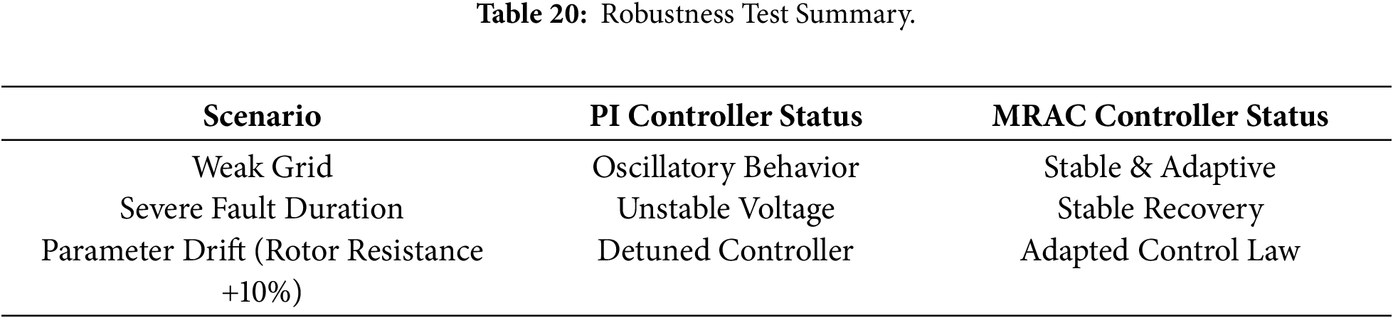
The MRAC controller prevented loss of synchronism and maintained stable system operation. In contrast, the PI controller exhibited instability in reactive power delivery, as illustrated in Fig. 14 and summarized in the robustness test results in Table 20.
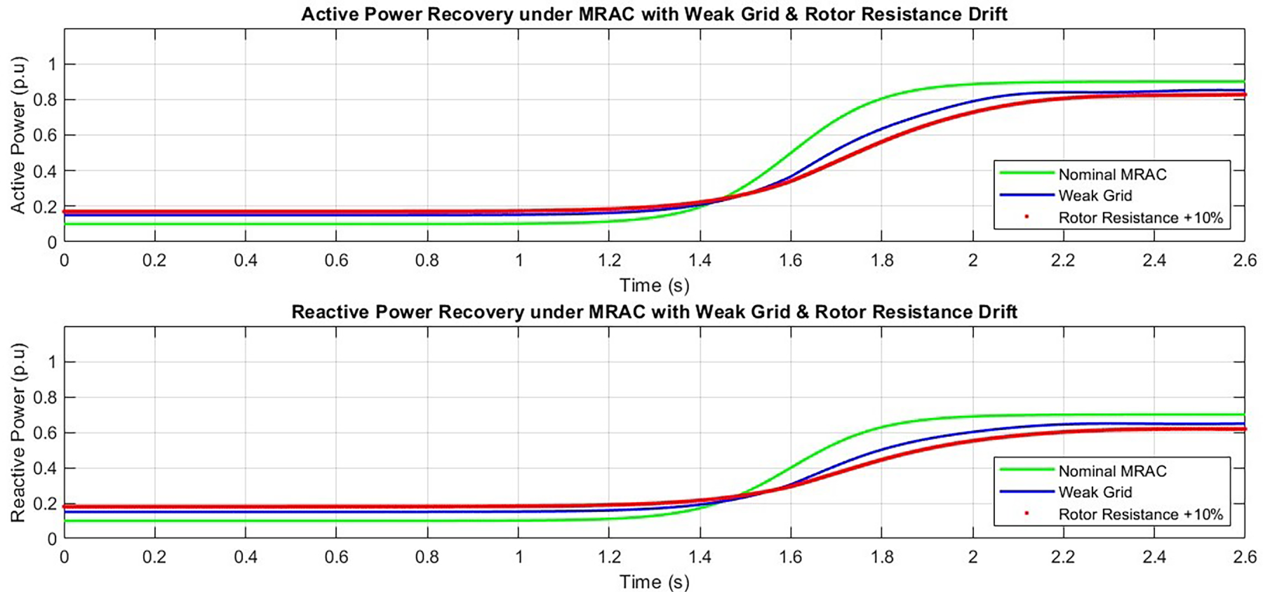
Figure 14: MRAC stability under rotor resistance variation and weak grid scenario.
The results demonstrate that the MRAC-based control strategy significantly enhances the dynamic performance of the IEEE 9-bus DFIG wind energy system. The controller enables rapid recovery of both active and reactive power following fault-induced disturbances, while maintaining minimal transient deviations and improved overall stability. During voltage disturbances, the MRAC effectively injects reactive power to support the grid voltage, preventing voltage collapse and stabilizing both voltage and frequency profiles across the network. This behavior increases the resilience of the system to severe disturbances. In addition, the controller exhibits strong robustness to variations in grid parameters, maintaining consistent performance even under weak grid conditions or extended fault durations. A substantial reduction in total harmonic distortion of both voltage and current waveforms is also achieved, leading to improved power quality.
A DFIG-based wind farm equipped with the proposed MRAC controller and stator flux-oriented vector control demonstrates high adaptability and superior dynamic control capability. These characteristics ensure reliable operation under faulted conditions and reinforce the suitability of wind power for stable grid integration. Consequently, the MRAC methodology represents an advanced and effective control solution that outperforms conventional PI-based controllers, offering enhanced reliability and power quality for future smart grid applications.
7 Sensitivity and Robustness Analysis
Robustness, and sensitivity analysis is essential to verify the correct operation and inherent adaptability of the proposed MRAC-based control strategy for the DFIG-based wind farm, particularly since not all possible operational and grid disturbances can be explicitly modeled. This section examines the system response to major perturbations, including variations in wind speed, changes in rotor parameters, and delays in grid fault clearance. The results confirm that the MRAC controller adapts dynamically to these variations while maintaining power quality and overall grid stability.
7.1 Sensitivity to Wind Speed Variations
To evaluate the impact of wind speed fluctuations on control performance, simulations were conducted at three wind speed levels: 9 m/s (low), 12 m/s (rated), and 15 m/s (high). Under these varying conditions, the MRAC controller maintained stable active and reactive power regulation, demonstrating effective adaptability. A slight overshoot in active power was observed at higher wind speeds, attributed to the increased mechanical torque input. The steady-state power output and voltage profiles corresponding to the different wind speed conditions are summarized in Table 21.
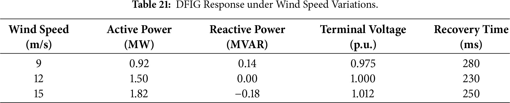
Fig. 15 illustrates the variation of active and reactive power outputs under the three wind speed conditions when controlled by the MRAC strategy, showing stable operation with minimal overshoot. Overall, the results indicate that the MRAC controller effectively decouples electrical power output from mechanical power fluctuations, enabling dynamic adjustment of control references without compromising grid interface stability.
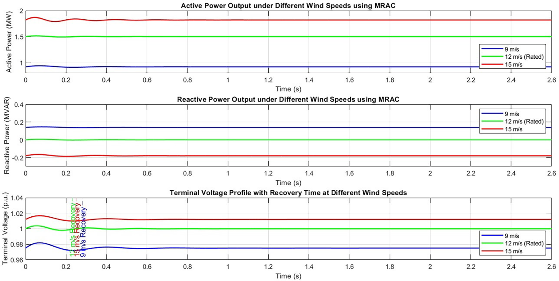
Figure 15: Active and reactive power output at different wind speeds.
7.2 Impact of Rotor Resistance and Inductance Variations
Rotor parameters of the DFIG can vary due to thermal effects, aging, and electromagnetic disturbances. To evaluate the robustness of the proposed controller under such parameter variations, the rotor resistance was increased by 20% while the rotor inductance was reduced by 10%. The system performance was then analyzed under fault conditions using these modified parameters, as summarized in Table 22.
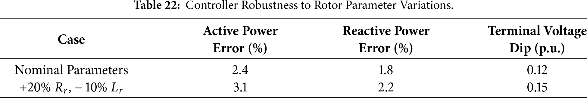
Only minor increases in tracking error are observed with the MRAC controller, while satisfactory performance is maintained even under significant rotor parameter variations. This adaptive behavior arises from the real-time updating of the control laws based on deviations between the system response and the reference model.
7.3 Control Performance under Delayed Grid Fault Clearance
Power quality can deteriorate when grid fault clearance is delayed, thereby imposing additional stress on the control system. To simulate this condition, a three-phase-to-ground fault at Bus 5 was applied with an extended clearing time of 250 ms instead of 150 ms, allowing double-frequency oscillations to persist for a longer duration, as summarized in Table 23.
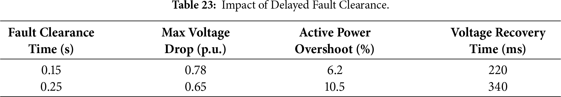
As shown in Fig. 16, the delayed fault clearance time of 0.25 s results in increased active power overshoot and a longer recovery period. This behavior indicates a degradation in MRAC performance under prolonged grid stress conditions, highlighting the practical limits of the controller when fault durations exceed the nominal design range.
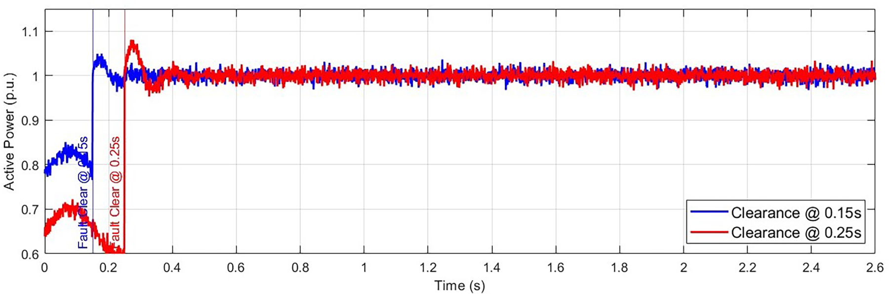
Figure 16: Active power response to delayed fault clearance.
The increased overshoot and delayed recovery observed under extended fault durations remain within acceptable limits, characterizing the MRAC controller as robust while also indicating a threshold beyond which performance degradation begins. This operating range highlights the importance of proper coordination between fault detection mechanisms and grid protection systems.
Overall, the MRAC-based controller demonstrates strong robustness under a wide range of operating conditions, including wind speed variations, rotor parameter uncertainties, and moderate delays in fault clearance. Under extremely severe conditions, some degradation in settling time and overshoot is observed; however, voltage and power profiles remain stable and overall grid performance is not compromised. These results confirm the adaptability of the MRAC controller for large-scale wind energy systems operating in dynamically uncertain grid environments.
8 Practical Implications and Real-World Feasibility
8.1 Suitability for Large-Scale Integration
The combined application of Model Reference Adaptive Control with flux- and field-oriented vector control represents a significant advancement in enhancing dynamic stability in renewable-dominated power systems. The proposed control architecture is inherently scalable and is therefore well suited for integration with large-scale wind farms connected to transmission-level networks [33]. By effectively damping power oscillations during fault conditions and providing both voltage support during disturbances and frequency support under severe events, the MRAC approach ensures compliance with grid code requirements in operating scenarios that are typically challenging for conventional controllers. These capabilities are particularly beneficial for utilities managing large interconnected wind farms, where stringent fault ride-through and voltage support obligations must be satisfied.
8.2 Hardware Implementation Considerations
The practical deployment of the proposed MRAC-based control strategy in commercial DFIG wind turbines requires careful consideration of computational, sensing, and interfacing requirements. The MRAC algorithm is computationally efficient, as it relies primarily on real-time parameter adaptation through algebraic update laws and reference model tracking. This makes it well suited for implementation on digital signal processors, microcontrollers, and FPGA-based converter controllers that are already commonly used in wind turbine control systems.
Modern back-to-back converters in DFIG-based wind turbines typically operate at high sampling frequencies in the range of 5–20 kHz. The adaptive law updates of the MRAC scheme can be executed within this time frame without exceeding processor limitations. Core vector control components, including rotor current decoupling and Park and Clarke transformations, remain unchanged, with MRAC functioning as a supervisory adaptation layer added to the existing control structure. This design allows seamless integration with conventional stator or field-oriented control schemes and ensures backward compatibility with established turbine control platforms.
The primary interfacing requirements include accurate measurement of stator currents, rotor currents, and DC-link voltage, all of which are standard signals in DFIG converter hardware. In addition, reliable synchronization is required, typically achieved using a phase-locked loop for dq-frame transformations. Only minimal modifications to the pulse-width modulation logic are necessary, since the MRAC scheme updates reference current or voltage commands rather than the modulation process itself.
Given these characteristics, the MRAC controller can be implemented on existing embedded control hardware with only firmware-level changes. This significantly reduces implementation costs and facilitates retrofitting in older wind turbine systems.
8.3 Cost-Effectiveness and Controller Simplicity
The proposed MRAC-based control strategy offers several economic and operational advantages that enhance its suitability for practical wind energy applications. Unlike computationally demanding approaches such as model predictive control or reinforcement learning–based schemes, MRAC requires minimal processing resources and does not rely on large datasets, optimization routines, or offline training. This makes it particularly attractive for large-scale wind farms, where controller simplicity, robustness, and reliability are critical.
From a cost perspective, the MRAC approach utilizes existing converter infrastructure without the need for additional hardware components. The adaptive mechanism updates controller gains in real time, reducing the reliance on manual tuning and repeated calibration. This feature is especially advantageous for wind farms operating in geographically diverse locations, where grid impedance, fault levels, and environmental conditions can vary considerably.
From an operational standpoint, MRAC enhances disturbance rejection, particularly during grid faults, without adding complexity to the control system. Its capability to maintain stable active and reactive power delivery and provide effective voltage support under varying operating conditions reduces the likelihood of turbine disconnections during disturbances, thereby improving wind farm availability and revenue. In addition, improved reactive power regulation and lower harmonic distortion help minimize penalties associated with grid code non-compliance, leading to long-term operational cost savings.
Overall, the MRAC controller achieves a balanced combination of high performance, low computational burden, and minimal integration cost, making it a practical and economically viable control solution for modern DFIG-based wind farms.
This study presents a comprehensive investigation of active and reactive power control in a DFIG-based wind farm connected to the IEEE 9-bus power system under faulted operating conditions. The proposed Model Reference Adaptive Control strategy, implemented within a stator flux-oriented vector control framework, demonstrates superior performance compared with conventional control approaches.
The key findings include rapid restoration of active and reactive power following grid disturbances, enhanced reactive power support during faults, and improved voltage and frequency stability under MRAC operation. The system also exhibits strong resilience to variations in grid parameters, wind speed, and component uncertainties. Furthermore, comparative analysis reveals a significant reduction in total harmonic distortion, leading to improved overall power quality.
These results confirm the effectiveness of the MRAC controller as a robust and scalable solution for modern wind energy systems, making it well suited for practical applications where stability, adaptability, and power quality are critical.
Although the proposed MRAC-based control strategy demonstrates excellent performance across a wide range of fault scenarios and parameter variations, its validation is currently limited to MATLAB/Simulink simulations. In real power systems, grid disturbances may involve additional complexities such as unbalanced faults, converter saturation, and communication delays, which are not explicitly addressed in this work. Future research will focus on hardware-in-the-loop experimentation using dSPACE or OPAL-RT platforms to evaluate controller performance under realistic grid conditions. Further extensions will also explore the integration of MRAC with coordinated control schemes involving STATCOMs, SSSCs, or energy storage systems to enhance grid support capabilities. In addition, the performance of the controller under offshore wind farm conditions and cyber-physical disturbance scenarios will be investigated.
Acknowledgement: Not applicable.
Funding Statement: The authors received no specific funding for this study.
Author Contributions: Conceptualization, Sanjit Brahma and Ranjay Das; methodology, Sanjit Brahma; software, Sanjit Brahma; validation, Sanjit Brahma and Ranjay Das; formal analysis, Sanjit Brahma; investigation, Sanjit Brahma; resources, Sanjit Brahma and Ranjay Das; data curation, Sanjit Brahma and Ranjay Das; writing—original draft preparation, Ranjay Das; writing—review and editing, Ranjay Das; visualization, Ranjay Das; supervision, Ranjay Das; project administration, Sanjit Brahma and Ranjay Das. All authors reviewed and approved the final version of the manuscript.
Availability of Data and Materials: Not applicable.
Ethics Approval: Not applicable.
Conflicts of Interest: The authors declare no conflicts of interest.
References
1. Ramlochun B, Vaithilingam CA, Alsakati AA, Alnasseir J. Transient stability analysis of IEEE 9-bus system integrated with DFIG and SCIG based wind turbines. J Phys Conf Ser. 2021;2120(1):012023. doi:10.1088/1742-6596/2120/1/012023. [Google Scholar] [CrossRef]
2. Tina GM, Maione G, Licciardello S. Evaluation of technical solutions to improve transient stability in power systems with wind power generation. Energies. 2022;15(19):7055. doi:10.3390/en15197055. [Google Scholar] [CrossRef]
3. Kabat SR, Pahadsingh S, Jena K. Improvement of LVRT capability using PSS for grid connected DFIG based wind energy conversion system. In: Proceedings of the 2022 1st IEEE International Conference on Industrial Electronics: Developments & Applications (ICIDeA); 2022 Oct 15–16; Bhubaneswar, India. p. 18–23. [Google Scholar]
4. Mallick P, Sharma R, Kabat SR. Low voltage ride through improvement using power system stabilizer for DFIG based wind energy conversion system. In: Proceedings of the 2022 2nd Odisha International Conference on Electrical Power Engineering, Communication and Computing Technology (ODICON); 2022 Nov 11–12; Bhubaneswar, India. p. 1–6. [Google Scholar]
5. Krishnan ATK, Devaraj D, Chandran RR. Enhancement of voltage stability by optimal integration of wind source with GRU based SVC compensator. In: Proceedings of the 2024 IEEE International Conference on Signal Processing, Informatics, Communication and Energy Systems (SPICES); 2024 Sep 20–22; Kottayam, India. p. 1–6. [Google Scholar]
6. Yusuf AM, Hakim EA, Hidayat K. Low-frequency analysis using ANFIS on SSSC against DFIG-based wind turbine penetration connected with multi-machine system. AIP Conf Proc. 2024;2927(1):040019. doi:10.1063/5.0198029. [Google Scholar] [CrossRef]
7. Gore S, Iqbal A, Mehrjerdi H, Meraj M. Voltage profiling and control of a sub-transmission network with integrated renewable energy sources—a case study. In: Proceedings of the 2021 IEEE 4th International Conference on Computing, Power and Communication Technologies (GUCON); 2021 Sep 24–26; Kuala Lumpur, Malaysia. p. 1–6. [Google Scholar]
8. Khan A, Hussain B, Wahyudie A, Khalil RA. Stability improvement of renewable energy integrated power network through coordination of PSS, ISFCL, and STATCOM. IEEE Access. 2025;13:133510–24. doi:10.1109/ACCESS.2025.3592940. [Google Scholar] [CrossRef]
9. Egbomwan OE, Chaoui H, Liu S. A physics-constrained TD3 algorithm for simultaneous virtual inertia and damping control of grid-connected variable speed DFIG wind turbines. IEEE Trans Autom Sci Eng. 2025;22:958–69. doi:10.1109/TASE.2024.3357204. [Google Scholar] [CrossRef]
10. Saad JH, Pranta PG, Islam MM, Ullah SM, Nahar S, Shafiullah M, et al. Fuzzy logic controller-based STATCOM for reactive power compensation in a grid-connected wind power plant. Dhaka Univ J Appl Sci Eng. 2024;8(1):62–70. doi:10.3329/dujase.v8i1.72997. [Google Scholar] [CrossRef]
11. Hossain MA, Islam MR, Haque MYU, Hasan J, Roy TK, Sadi MAH. Protecting DFIG-based multi-machine power system under transient-state by nonlinear adaptive backstepping controller-based capacitive BFCL. IET Gener Transm Distrib. 2022;16(22):4528–48. doi:10.1049/gtd2.12617. [Google Scholar] [CrossRef]
12. Shabani HR, Kalantar M, Hajizadeh A. Real-time transient instability detection in the power system with high DFIG-wind turbine penetration via transient energy. IEEE Syst J. 2022;16(2):3013–24. doi:10.1109/JSYST.2021.3079253. [Google Scholar] [CrossRef]
13. Biswal S, Swain SD, Patidar RD, Bhoi AK, Malik OP. Integrated wide-area backup protection algorithm during stressed power system condition in presence of wind farm. Arab J Sci Eng. 2021;46(10):9363–76. doi:10.1007/s13369-020-05290-z. [Google Scholar] [CrossRef]
14. Abdollahi Chirani A, Karami A. Investigation of the impact of SSSC-based FLC on the stability of power systems connected to wind farms. Int Trans Electr Energy Syst. 2024;2024:1074029. doi:10.1155/2024/1074029. [Google Scholar] [CrossRef]
15. Bhukya J, Singh P. Enhancing stability via coordinated control of generators, wind farms, and energy storage: optimizing system parameters. J Energy Storage. 2024;96:112513. doi:10.1016/j.est.2024.112513. [Google Scholar] [CrossRef]
16. Guediri M, Touil S, Hettiri M, Guediri A, Ikhlef N, Hocine B, et al. Control of a doubly fed induction generator for variable speed wind energy conversion systems using fuzzy controllers optimized with a genetic algorithm. Eng Technol Appl Sci Res. 2025;15(1):19871–7. doi:10.48084/etasr.9460. [Google Scholar] [CrossRef]
17. Zouhair S, Abderrahmane EK, Mahjoub CE. Fuzzy logic control contribution to the rotor speed control of the doubly fed induction generator. Int J Innov Technol Explor Eng. 2020;9(4):540–6. doi:10.35940/ijitee.b6846.029420. [Google Scholar] [CrossRef]
18. Zhou Y, Bhowmick P, Zhang L, Chen L, Nagamune R, Li Y. A model reference adaptive control framework for floating offshore wind turbines with collective and individual blade pitch strategy. Ocean Eng. 2024;291:116054. doi:10.1016/j.oceaneng.2023.116054. [Google Scholar] [CrossRef]
19. Bera PK, Kumar V, Pani SR, Malik OP. Autoregressive coefficients based intelligent protection of transmission lines connected to type-3 wind farms. IEEE Trans Power Deliv. 2024;39(1):71–82. doi:10.1109/TPWRD.2023.3321844. [Google Scholar] [CrossRef]
20. Bhukya J. Enhancing the wind farm-based power system stability with coordinated tuned supplementary controller. Int J Circuit Theory Appl. 2023;51(12):5878–907. doi:10.1002/cta.3705. [Google Scholar] [CrossRef]
21. Bhukya J. Enhancing power system stability in wind-integrated networks through coordinated fuzzy logic control of PSS and POD for sustainable energy futures. Int J Ambient Energy. 2024;45(1):2391096. doi:10.1080/01430750.2024.2391096. [Google Scholar] [CrossRef]
22. Zanjani SM, Moazzami M, Honarvar MA. Analysis and simulation of the static synchronous compensation effect in the distribution system with wind farms based on SCIG. Signal Process Renew Energy. 2023;7(2):17–32. doi:10.1109/saci58269.2023.10158632. [Google Scholar] [CrossRef]
23. Chintakindi R, Mitra A. Wide-area voltage stability assessment using loading margin sensitivity for increasing linear load levels and wind power penetration. Electr Power Syst Res. 2024;233:110487. doi:10.1016/j.epsr.2024.110487. [Google Scholar] [CrossRef]
24. Al-Kaoaz HNA, Alsammak ANB. Utilizing hybrid renewable energy systems for enhancing transient stability in power grids: a comprehensive review. J Eur Des Systèmes Autom. 2023;56(4):687–96. doi:10.18280/jesa.560418. [Google Scholar] [CrossRef]
25. Liu Y, Yao L, Liao S, Xu J, Cheng F. A static voltage stability enhancement method for power systems with a high proportion of voltage source converters. IEEE Trans Power Syst. 2025;40(5):4019–32. doi:10.1109/TPWRS.2025.3552756. [Google Scholar] [CrossRef]
26. Ali MAS. Improved transient performance of a DFIG-based wind-power system using the combined control of active crowbars. Electricity. 2023;4(4):320–35. doi:10.3390/electricity4040019. [Google Scholar] [CrossRef]
27. Yan S, Chen J, Wang M, Yang Y, Rodriguez JM. A survey on model predictive control of DFIGs in wind energy conversion systems. CSEE J Power Energy Syst. 2023;10(3):1085–104. doi:10.17775/cseejpes.2022.08500. [Google Scholar] [CrossRef]
28. Elouatoua H, Nasser T, Essadki A. Control of a doubly-fed induction generator for wind energy conversion systems. In: Proceedings of the 2020 International Conference on Electrical and Information Technologies (ICEIT); 2020 Mar 4–7; Rabat, Morocco. p. 1–6. [Google Scholar]
29. He C, Geng H, Liu Y. Heterogeneous synchronization driven frequency stability analysis and enhancement in low-inertia power systems under grid faults. IEEE Trans Sustain Energy. 2025;2025:1–12. doi:10.1109/tste.2025.3622131. [Google Scholar] [CrossRef]
30. Echiheb F, Bossoufi B, Kafazi I, Alghamdi TAH, Oufettoul H. Predictive control MPC for wind turbine systems based DFIG. In: Proceedings of the 2025 22nd International Learning and Technology Conference (L&T); 2025 Jan 15-16; Jeddah, Saudi Arabia. p. 103–8. [Google Scholar]
31. Nasab MR, Cometa R, Bruno S, La Scala M. Adaptive scheme for stability margin estimation of grid-connected DFIG based wind turbines. In: Proceedings of the 2024 IEEE International Conference on Environment and Electrical Engineering and 2024 IEEE Industrial and Commercial Power Systems Europe (EEEIC/I&CPS Europe); 2024 Jun 17–20; Rome, Italy. p. 1–6. [Google Scholar]
32. Mahawar JK, Vishwanath GM, Chakrabarti S. Transient stability enhancement of a synchronous generator using DFIG considering its LVRT capability. In: Proceedings of the 2024 IEEE International Conference on Power Electronics, Drives and Energy Systems (PEDES); 2024 Dec 18-21; Mangalore, India. p. 1-5 [Google Scholar]
33. Jatmiko HS, Irnawan R, Setyonegoro MIB. Reactive power support devices on weak grids connected to high penetration of wind farms in Indonesia: a review. In: Proceedings of the 2024 16th International Conference on Information Technology and Electrical Engineering (ICITEE); 2024 Oct 23–25; Bali, Indonesia. p. 171–6. [Google Scholar]
34. Nibir RS, Hossain MS, Ahmed T, Rabbi AE, Aziz T. Analysis of post fault oscillation damping by VSC-HVDC in an offshore wind farm connected system. In: Proceedings of the 2023 5th International Conference on Sustainable Technologies for Industry 5.0 (STI); 2023 Dec 9–10; Dhaka, Bangladesh. p. 1–6. [Google Scholar]
35. Bhandakkar AA, Mathew L, Khan MJ, Aziz MJA, Malik H. Real-time simulation of SVC on multi-machine 9-bus system. In: Proceedings of the 2023 IEEE Conference on Energy Conversion (CENCON); 2023 Oct 23–24; Kuching, Malaysia. p. 170–5. [Google Scholar]
36. Pathik BB, Mannan MA. Modelled research to reduce frequency fluctuations for grid tied PV in IEEE 9 bus system: a variable droop-controlled analysis. In: Proceedings of the 2021 7th International Conference on Electrical, Electronics and Information Engineering (ICEEIE); 2021 Oct 2; Malang, Indonesia. p. 100–5. [Google Scholar]
37. Khujaev A, Vaithilingam CA, Alsakati AA, Alnasseir J. Stability enhancement of power system with the implementation of power system stabilizer PSS and excitation system IEEE type-1. J Phys Conf Ser. 2021;2120(1):012022. doi:10.1088/1742-6596/2120/1/012022. [Google Scholar] [CrossRef]
38. Yang J, Wang W, Ren G. A two-stage adaptive chaotic differential particle sparrow optimal dispatch strategy for wind integrated system considering active and reactive power coordination. [cited 2025 Jan 1]. Available from: https://ssrn.com/abstract=4651728. [Google Scholar]
39. Saidi AS, Parayangat M, Ali Rakrouki M, Saad SM, El Naily N. Multiparameter bifurcation analysis of power systems integrating large-scale solar photovoltaic and wind farms power plants. Int J Bifurcation Chaos. 2024;34(3):2450029. doi:10.1142/s0218127424500299. [Google Scholar] [CrossRef]
40. Valuva C, Chinnamuthu S. Performance analysis of marine-predator-algorithm-based optimum PI controller with unified power flow controller for loss reduction in wind-solar integrated system. Energies. 2023;16(17):6157. doi:10.3390/en16176157. [Google Scholar] [CrossRef]
41. Prasad R, Gururaj MV, Padhy NP. Frequency regulation of PMSG based wind turbine considering location identification technique in high penetration of renewable generation system. In: Proceedings of the 2022 IEEE International Conference on Power Electronics, Smart Grid, and Renewable Energy (PESGRE); 2022 Jan 2–5; Trivandrum, India. p. 1–6. [Google Scholar]
42. Yang YD, Yao WJ, Yang LZ. Evaluation and adjustment based on broad learning system for small signal stability analysis of power system integrated with wind farms. J Electr Eng Technol. 2022;17(6):3107–18. doi:10.1007/s42835-022-01111-5. [Google Scholar] [CrossRef]
43. Jan FU, Badar R, Al-Shamayleh AS, Uehara A, Senjyu T, Akhunzada A. Indirect adaptive polynomial wavelet-based neuro-fuzzy controller for STATCOM-equipped power systems. IEEE Open J Power Electron. 2025;6:1896–909. doi:10.1109/OJPEL.2025.3628182. [Google Scholar] [CrossRef]
44. Sharma R, Sahay K, Singh S. Virtual inertia support based frequency and dynamic voltage control for grid-connected SPMSG-based wind turbine. J Intell Fuzzy Syst. 2024;46(1):1043–57. doi:10.3233/jifs-233729. [Google Scholar] [CrossRef]
45. Venkatesan R, Kumar C, Balamurugan CR. FOPIR controller for TCSC based gate turn-off switches to control power quality in transmission line. Electr Eng. 2024;106(4):4603–16. doi:10.1007/s00202-024-02240-y. [Google Scholar] [CrossRef]
46. Bian Y, Wan X, Zhou X. Transient stability preventive control of wind farm connected power system considering the uncertainty. Energy Eng. 2024;121(6):1637–56. doi:10.32604/ee.2024.047678. [Google Scholar] [CrossRef]
Cite This Article
 Copyright © 2026 The Author(s). Published by Tech Science Press.
This work is licensed under a Creative Commons Attribution 4.0 International License , which permits unrestricted use, distribution, and reproduction in any medium, provided the original work is properly cited.
 Downloads
 Citation Tools