
 Submit a Paper
 Propose a Special lssue
 Open Access
ARTICLE

Investigation of a Closed-Loop Electrohydraulic System Driven by a Variable Frequency Drive Based on a Programmable Logic Controller
Electromechanical Engineering College, University of Technology Iraq, Baghdad, Iraq
* Corresponding Author: Aws F. Hassan. Email:
(This article belongs to the Special Issue: Advancements in Energy Resources and Their Processes, Systems, Materials and Policies for Affordable Energy Sustainability)
Energy Engineering 2026, 123(4), 18 https://doi.org/10.32604/ee.2026.075837
Received 10 November 2025; Accepted 19 February 2026; Issue published 27 March 2026
 View Full Text
 Download PDF
Abstract
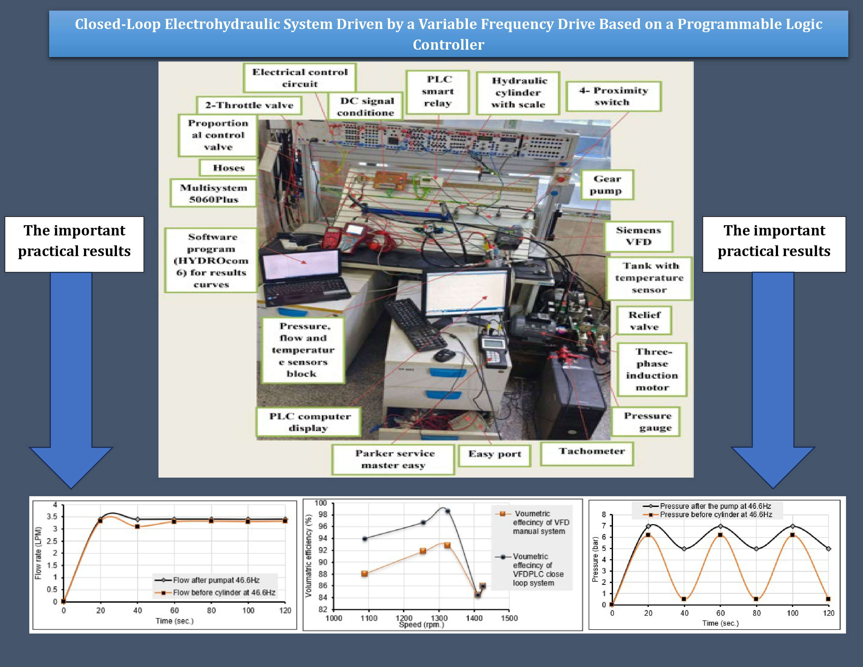
The current study aims to improve the performance of the electrohydraulic servo system (EHSS) by increasing the volumetric efficiency of the pump and reducing electrical power consumption to a minimum value. An experimental setup has been designed and built to control the cylinder position using a programmable logic controller to provide the appropriate motor speed from the AC drive to control the velocity of the hydraulic actuator; the induction motor is driven by an AC drive using a tune proportional-integral-variable frequency drive (TPI-VFD) space vector modulation (SVM) hybrid technology. Theoretically, it was analyzed and simulated by MATLAB, which showed that the starting current was reduced by 81% compared to the traditional system. Also, the settling time of the system decreased to 0.35 s to reach a steady state with a minimum error of 0.03 and an overshoot of 0.3%. On the other hand, the experimental results of the EHSS show that the three-phase induction motor with a closed-loop speed control AC drive with a programmable logic controller PLC based system is the best case for determining the appropriate operating speed. The optimum speed, frequency, and voltage were 1325.3 rpm, 46.6 Hz, and 354.16 V. In addition, enhancement is achieved in closed-loop VFD-PLC, where at 6.5 bar pressure and 3.4 LPM flow, the volumetric efficiency after the pump improves to 98.6% while it reaches 96.3% before the cylinder at a flow rate of 3.32 LPM. Finally, in the closed-loop VFD-PLC in the expansion stroke, the rated electrical power consumption of the three-phase IM decreased to 532 W at the speed of 1325.3 rpm, resulting in energy savings of 20.6%.Graphic Abstract
Keywords
Nomenclature
| Symbols | |
| A1,2 | Piston area (m2) |
| Ar | Rod area (m2) |
| d | Diameter (m) |
| F | Force (N) |
| f | Supply frequency (Hz) |
| fv | Viscosity coefficient of rotor friction |
| H | Inertia constant of the rotor/load set |
| hAT | Hole from port A to the tank in the directional valve |
| hBT | Hole from port B to the tank in the directional valve |
| hPA | Hole from the pressure port to port A in the directional valve |
| hPB | Hole from the pressure port to port B in the directional valve |
| I | Current (A) |
| AC current (A) | |
| DC current (A) | |
| Currents aligned with q-axis & d-axis | |
| kHP | Hagen-Poiseuille coefficient |
| kp, ki, kd | Proportional, integral, & derivative coefficients |
| ma | Modulation index |
| N | Motor speed RPM |
| p0 | Motor pole pair |
| P | Discharge pressure, Pa |
| qleak | Leakage flow |
| DC power at the SPWM technique | |
| DC power at the SVM technique | |
| Save power | |
| Pin, Pout | Input & output motor power (W) |
| PL, Ph | Load power & hydraulic power (W) |
| Q | Flowrate, LPM |
| Qa | Actual flow rate for hydraulic pump (m3/s) |
| Qt | Theoretical flow rate for hydraulic pump (m3/s) |
| Te | Electromagnetic torque (N m) |
| Tm | Mechanical torque on the shaft (N m) |
| Vac | AC peak voltage (V) |
| Vdc | DC voltage (V) |
| V | Voltage (V) |
| Vs | piston linear velocity (m/s) |
| Kinetic viscosity of the fluid (cSt) | |
| Vg | Geometrical volume of hydraulic pump (m3) |
| Greek letters | |
| Constant | |
| Fluid dynamic viscosity (Pa s) | |
| Φ | Air gap flux (Wb) |
| φqs, φds | Stator fluxes referred to d-axis & q-axis (Wb) |
| Pump mechanical & volumetric efficiencies | |
| ηt, η | Total efficiency & motor efficiency |
| θm | Angular position of the rotor (m) |
| η | Fluid dynamic viscosity (Pa s) |
| ρ | Fluid density (kg/m3) |
| Cos ϕ | Power factor |
| ωm | Angular velocity of the rotor (rad/s) |
| ω | Pump angular velocity (rad/s) |
| Abbreviations | |
| ANN | Artificial neural network |
| EHA | Electro-hydraulic actuator |
| EHSSs | Electro-hydraulic servo systems |
| IM | Induction motor |
| PDCV | Proportional directional control valve |
| PID | Proportional-integral-derivative |
| PLC | Programmable logic controller |
| TPI | Tune-proportional-integral |
| VFD | Variable frequency drive |
| VVVF | Variable voltage variable frequency |
Underwater operations, industrial applications, and construction vehicles all heavily rely on electrohydraulic servo systems (EHSSs). For hydraulic elevators, for example, precise velocity control is essential. Additionally, precise force control is necessary, such as load simulators. Tunnel boring machines, underwater manipulators, and robot manipulators must be able to manage both force and velocity [1]. Industrial machinery is becoming increasingly sophisticated these days. They employ a variety of hydraulic, pneumatic, and electrical technologies. Hydraulic systems are employed in operations that require tremendous power and precision. The hydraulic pump, which guarantees the appropriate flow of the working liquid, is the most crucial component of such systems [2]. With advances in frequency converters, the variable-speed electro-hydraulic drive, which consists of a speed-regulated electric motor coupled with a constant hydraulic pump, has greatly improved [3]. A three-phase induction motor (IM) has a wide range of uses in industries for electrical AC drives due to its affordability, simplicity of manufacture, longevity, and excellent dependability [4,5]. With the advent of the vector control technique, the control of an IM has evolved to resemble that of an independently stimulated DC motor for high-performance applications. This method allows independent regulation of the field and torque of a three-phase induction motor (IM) by modifying the required field-oriented parameters [6]. The common Vector Control approach for controlling the IM uses a tune Proportional-Integral (PI)controller in the outer speed loop because it is straightforward and stable. Controlling the velocity of an EHSS hydraulic cylinder is a common objective in the fluid power industry. This objective is achieved by controlling the quantity of hydraulic fluid that enters the cylinder. Many studies dealt with the control of electro-hydraulic and hydraulic systems, as well as some studies on the speed control of three-phase IMs.
The goal of the energy-saving technique used by Xu et al. [7] for a hydraulic system is to improve the efficiency of the energy usage of hydraulic elevators by using a variable voltage variable frequency (VVVF) controller. However, the cost is higher, and using the Proportional-Integral-Derivative (PID) control algorithm does not usually give accurate results. In contrast, the effects of two different control strategies for adjusting the actuator’s position in a hydraulic system while regulating the swash plate angle and electric motor speed of the main pump were investigated by Wrat et al. [8]. In terms of responsiveness and dynamic qualities, the swash plate control method outperformed alternative approaches in simulation and experiments. However, using a swash plate pump is extremely expensive research-wise and requires a supporting party. In addition, using a traditional PID does not achieve accurate results. Furthermore, the impact of altering the bulk modulus of elasticity on the functionality of traditional electro-hydraulic systems was investigated realistically by Hashim et al. [9]. However, this modification in the aforementioned study did not prevent the elimination of many problems that accompany the operation of traditional hydraulic systems.
A traditional PI controller was used in the experimental work of Mohammed et al. [10] based on the proportional valve and fixed displacement pump of hydraulic elevator speed. This control relied on adjusting the proportional solenoid valve to control the flow rate, which in turn controlled the speed of the hydraulic cylinder or the elevator’s up-and-down motion. Though such a high overshoot and ripple in speed. Zagar et al. [11] introduced and studied a digital valve control idea. The results demonstrated that the control force fluctuated less than the pump control and that the mean control error during the load-holding phase was within the intended band. Apart from this, an expensive variable displacement pump was used, and this idea was only used at low speeds. On the other hand, a precise motion tracking method for a hydraulic actuator with unknown negative loads was introduced by Helian et al. [12]. A servomotor pump powers the actuator’s motion, achieving both motion tracking precision and excellent energy economy.
Since IMs are often operated at a set speed, adjusting the motor’s speed is crucial to achieve a new speed and frequency that is appropriate for the task that the motor is given. In certain cases, V/f control was used [13]. Other research employed sophisticated methods. Andrade-Cedeno et al. [14] presented two cases, one with one pump running at a constant speed and the other at variable speed powered by an IM in a pumping station with variable flow demand, and the other with both pumps running at variable speed is modeled, simulated, and numerically studied. Indeed, both scenarios smoothed down the current at the start and maintained a steady pressure despite fluctuating flow demand. Nevertheless, the second case produced higher harmonic distortion but saved more energy, 28%–49%.
Furthermore, the limitations were high cost due to the use of variable displacement and fixed displacement pumps with induction motors, as well as distortion harmonics generated. Also, Rashad and Hassan [5] designed and simulated a VVVF drive based on a sinusoidal PWM voltage source inverter. They proposed a nonlinear autoregressive moving average neural network (NARMA-L2) and trained it as a closed-loop slip regulation controller. Also, complex methods and reducing drawbacks associated with conventional controllers, such as overshoot and settling time, are exceedingly difficult. Dahmardeh et al. [4] introduced a unique Direct Torque Control (DTC) technique and Stator-Flux Orientated Control (SFOC) system to improve the general performance of three-phase IM drives. This technique is used only for a low-power 2.5 kW three-phase system. Okeke and Okonkwo [15] and Ojha et al. [6] suggested that the system combine an intelligence algorithm based on fuzzy logic control (FLC) with a classical (PID) controller for IM speed control. Indeed, it reduces but is not able to eliminate drawbacks associated with conventional controllers, such as overshoot, long settling time, and steady state error common with FLC. Compared to PID controllers, FLC performed better and settled more quickly. To regulate the speed of a three-phase induction machine, Prasetia and Ramadani [16] suggested a PID controller, which is most often used in the field of control systems. The motor speed response had a time constant of 1.5 s, a rising time of 2.2 s, and a setting time of 2.7 s. However, this method was used to reduce drawbacks associated with controllers, such as overshoot and settling time, but did not reach the optimum values.
In comparison, Hassan et al. [17] simulated the used PI-FL-IVC to manage the speed of an indirectly controlled vector-controlled three-phase IM that drives an Electro-hydraulic actuator (EHA) using the MATLAB-Simulink program. The results prove that the indirect field-oriented control technique with PI fuzzy logic control provides better speed control of the IM, by reducing the steady state error to 0.024, overshooting to 0.2% and settling time to 0.3 s. Finally, an electro-hydraulic vibration control system based on the single-neuron PID algorithm was suggested by Jia et al. [18], which increased the load force’s control precision and the electro-hydraulic fatigue testing machine’s working frequency.
Most of the previous studies dealt with hydraulic system control, IM rotational speed control, and electro-hydraulic systems in different ways. Some of these methods are environmentally harmful, complex, or cost-effective, some are traditional, and others are effective. Previous studies varied in the control methods. Some used purely hydraulic control by controlling the valve, pump, or actuator, and some used motor speed control through different methods (classical PID, Fuzzy PID, FLC, and Artificial Neural Network (ANN)). The present paper aims to improve the electro-hydraulic system under study by designing and implementing advanced control to increase the volumetric efficiency of the pump and reduce electrical power consumption to a minimum value. To obtain the shortest response time of traditional hydraulic systems, the pump remains in operation even though the useful load is not applied. Pressure relief valves are often used in hydraulic systems to prevent excessive pressure. These valves open to reroute oil flow and release excess pressure when the pressure reaches a certain limit, protecting the system from harm.
To maintain effective operation and reduce excessive energy use, it is essential to balance the load requirements. So, the modification is to use a closed-loop system to control the three-phase IM at the desired speed according to the load requirements and drive the EHSS through PLC programming. Three speeds of AC drive were used, with the addition of a common fourth speed when reversing in the cylinder contraction stroke. Speed control relies on feedback signals coming from position sensors outside the hydraulic system. The system will be more accurate, have a higher volumetric efficiency, the flow will be higher, and it will save more electric power of IM, thus saving energy for EHSS.
2.1 Modeling and Proposal of Electro-Hydraulic Control System
The intelligent speed controller for a three-phase IM, which drives an electro-hydraulic servo system loaded by spring, damper, and mass system, is shown in the block diagram of Fig. 1 and is based on VFD-SVM.
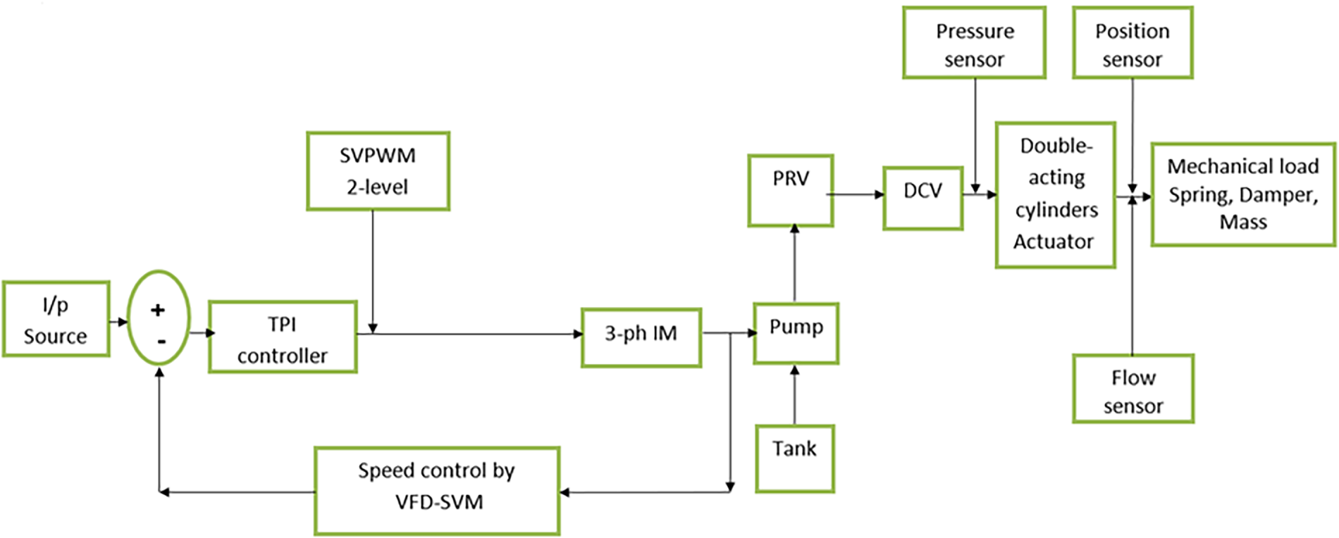
Figure 1: VFD-SVM control of electro-hydraulic servo system.
The particular features and elements of a hydraulic system determine its governing equations. However, hydraulic analysis frequently uses a few basic equations. Merritt’s work [19] provides the theoretical model for the majority of the hydraulic system’s components, which is used to specify the system’s transfer function.
i. Hydraulic Pump
Leakage flow can be calculated using the Hagen-Poiseuille formula [20,21], which assumes that it is linearly proportional to the pressure differential across the pump:
Undoubtedly, the mechanical efficiency of pumps is rarely included in the data sheets; hence, it is determined using the volumetric and total efficiencies under the assumption that the hydraulic efficiency is extremely low.
where the hydraulic pump volumetric efficiency is:
By substituting Eq. (4) into Eq. (3), the final volumetric efficiency equation is:
The actual force that a pump exerts on a fluid is known as hydraulic power. The formula for hydraulic power is the following:
ii. Proportional Directional Control Valve
The SIMULINK modeling of the operation sequence of the Proportional directional control valve (PDCV) servo valve is shown in Fig. 2. The “Pulse Generator” signal is supplied to the valve because it works with a servo system. This signal was deliberately designed to regulate the duration of each period, i.e., as needed. More specifically, the operation of the PDCV is regulated by the pulse generator signal. The double-acting single rod cylinder (DAC) and the two-position sensors “PS” are connected, allowing the generator signal to power the complete system.
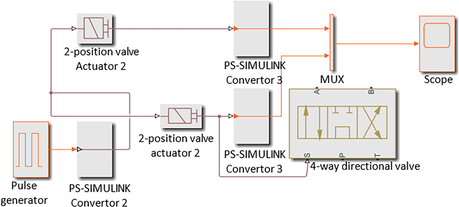
Figure 2: SIMULINK modeling of proportional directional control valve.
The holes in the directional control valve are opened (holes P-A and B-T), and the holes are closed (holes A-T and P-B), as shown in Fig. 3. The openings of the orifices are computed as follows:
iii. Actuator
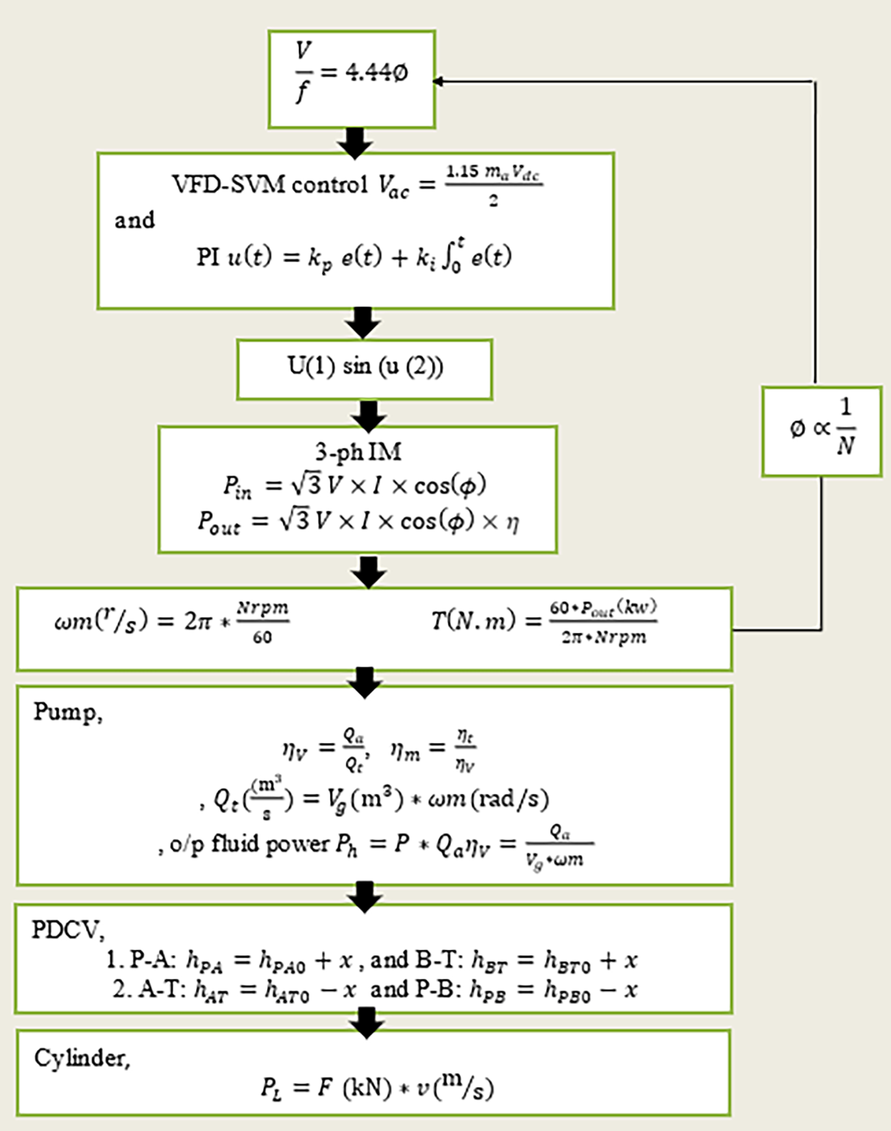
Figure 3: Sequence of the governing equations used in the EHSS-MATLAB.
Extension stroke:
Retraction stroke:
where
In metric units, the
where the flow rate
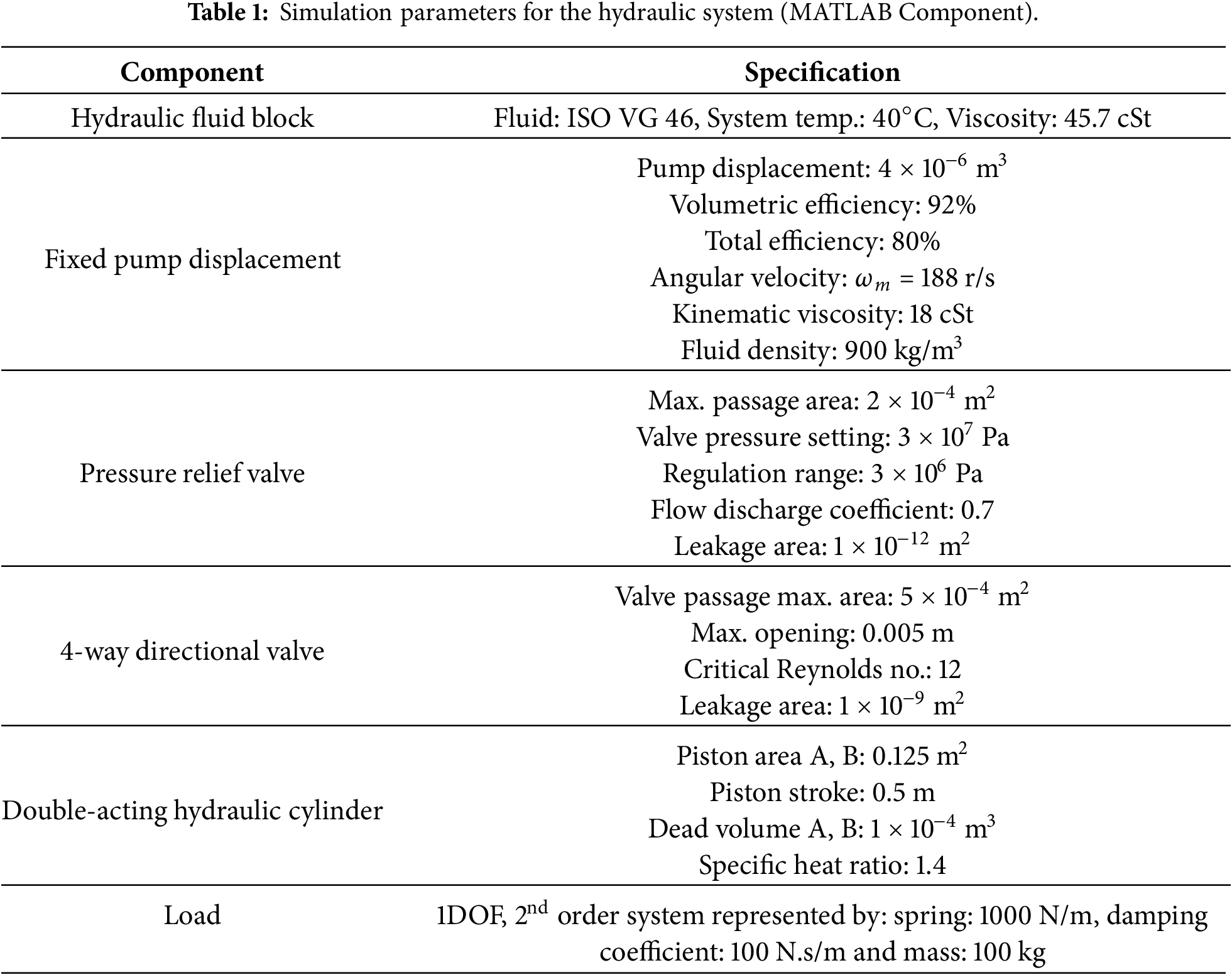
Table 1 provides hydraulic system simulation parameters. The component specifications have been adopted from [17].
2.1.2 Governing Equations for Intelligent Motor Drive Control
Three-phase IMs control the speed and voltage, using the voltage to frequency (V/f) control method, have been modeled to reach the required steady state of the EHSS system quickly and efficiently.
i. Modeling of Three-Phase IM
The torque, Te, of an electromagnetic motor is provided as follows [20,21]:
The mechanical system of the three-phase IM is given as,
The input power and output power dynamic equations of the squirrel cage IM, respectively, are (23) and (24):
where the torque,
And angular velocity,
ii. PID Controller
The purpose of the PID controller is to supply the required control signals to the 2-Level PWM generator. When compared to the required speed, the motor speed serves as feedback. So, the error signal is supplied as input by the PID controller. In order to control, attempts are made to reduce the error by altering the process control inputs [22]. The PID controller approach uses three independent constant parameters:
• proportional, P, which is based on the present error, e,
• integral, I, and
• derivative, D, which is a prediction of upcoming errors, and is based on the accumulation of previous errors [10]:
The PI controller is effective for many fast processes, such as flow, pressure, and some temperature loops. The PI controller is typically used for applications requiring speed control, as stated:
The fundamental frequency of the input voltage can be computed from the output signal of the PI controller as,
iii. VFD Vector Control
In dynamic scenarios, vector control provides closed-loop speed control with strong stability for the IM drive. Higher torque demand and flux variations can be reduced with the aid of direct torque control (DTC) controlled by SVM. A quicker response time to changes in speed and torque, and fewer ripples are provided by tuning the PI controller. MATLAB-SIMULINK simulation software was used to create the driving pattern of the electrical drive to evaluate the system speed control [8]. This method gives a higher run-time efficiency. Therefore, the majority of AC speed drives employ the constant V/f method (or VVVF method) for speed control. Along with a wide range of speed control, this method also offers soft start capability. The voltage induced in the stator is proportional to the product of the supply frequency and air gap flux [7]:
2.2 Proposed Save Energy Mathematical Model
By using MATLAB, the SVM approach reduces the voltage, which lowers the power and conserves energy. The IGBT inverter was driven by a voltage of 540 V. The following formulas may be used to reduce the needed voltage from 620 to 540 V, saving 80 V. This shows that using SVM increases the DC utilization factor by 15% compared to SPWM. The SPWM technique requires a DC voltage of 620 V to produce an AC peak voltage of 310 V. By adding a DC value of 80 V, the SVM technique reduces the necessary supply and permits source voltage savings, meaning that a 540 DC voltage is enough to produce 310 V of peak voltage. In the mathematical model suggested (Aws Al-Dulaimi model), the aforementioned text is illustrated by the following equations. The following conclusions can be drawn from the suggested energy-saving simulation model of MATLAB. For SPWM, Vdc = 620 V, Idc = 20 A, and the modulation index, ma: 0.999 ≅ 1.0:
For SVM
The energy saving, Esave for control test during 10 s, using Eq. (39), is:
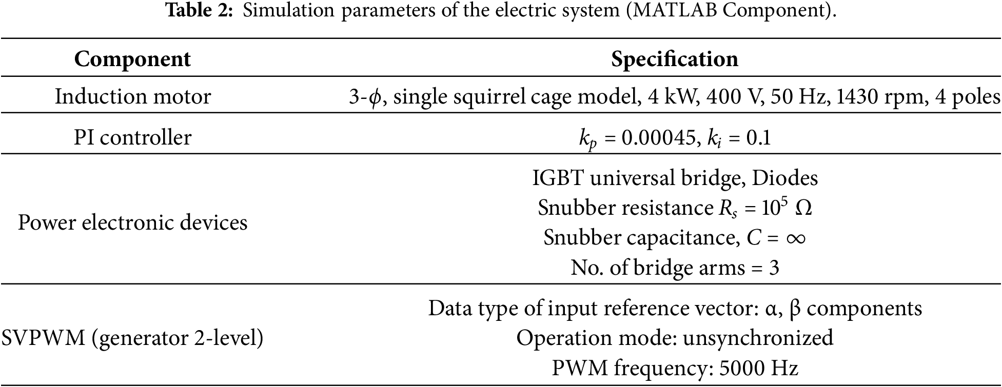
The energy saved for 3 kW is 30 kJ for a duration of 10 s, which represents around 25%. Table 2 demonstrates the simulated parameters of the electric system [20].
After the development of the mathematical models of each part, the sequence of the governing equations in the EHSS subroutines in the MATLAB mathematical model is presented in Fig. 3.
The entire electro-hydraulic servo system has been constructed. It should be noted that the electrical system and the hydraulic system are their two primary systems. In fact, a three-phase squirrel cage induction motor with a TPI-VFD-SVM control system, a two-level SVPWM generator, and an IGBT universal bridge make up the electric system seen in Fig. 4. In this case, the system’s primary goal is to regulate the induction motor’s speed in order to provide the fixed displacement pump with the necessary mechanical movement, which is required to modify the hydraulic flow rate in the hydraulic system’s parts.
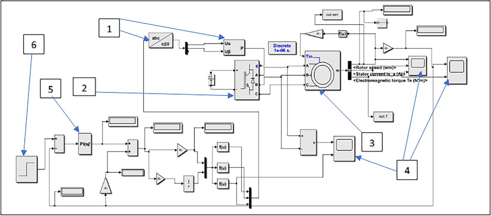
Figure 4: SIMULINK model for the electrical system: (1) two-level SVPWM generator, (2) IGBT universal bridge, (3) a three-phase induction motor, (4) scope, (5) TPI controller, (6) step input signal.
Hydraulic fluid, a tank, lines, a fixed displacement pump (gear pump), a relief valve, a double-acting cylinder, a PDCV, a position sensor, a flow rate sensor, a pressure sensor, and a load (mass-spring-damper) make up the hydraulic system model depicted in Fig. 5.
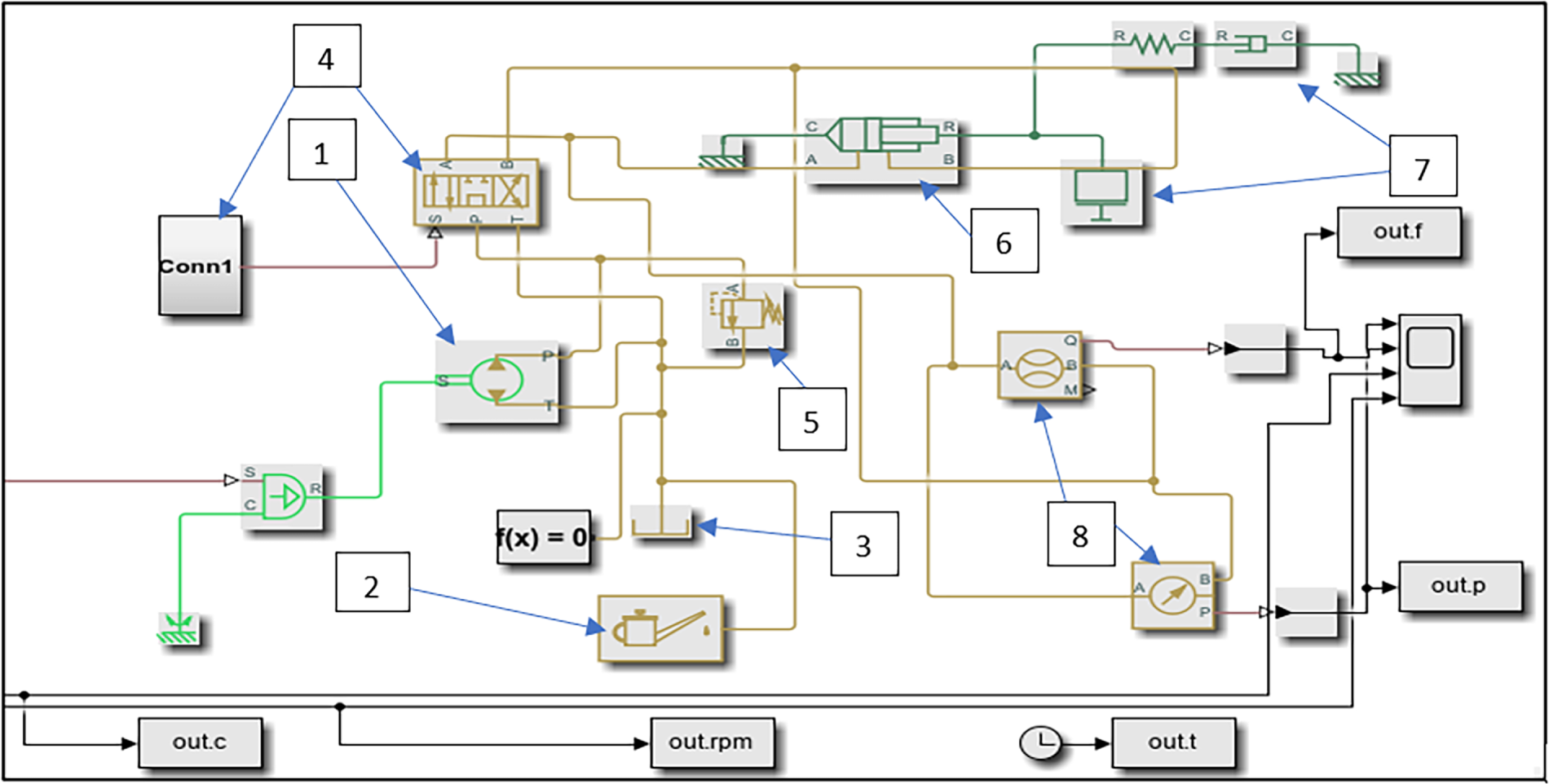
Figure 5: SIMULINK model for hydraulic system: (1) a fixed displacement pump (gear pump), (2) hydraulic fluid, (3) tank, (4) proportional directional control valve, (5) relief valve, (6) double-acting cylinder, (7) load (mass-spring-damper), (8) flow rate and pressure sensors.
The experimental work of EHSS is divided into three parts. First, explaining the components of the system, second, explaining the PLC system and work procedures, and finally, explaining the DC signal conditioner.
The schematic diagram of the EHSS is shown in Figs. 6 and 7, which illustrates the setup of the closed-loop EHSS prototype. It should be noted that the proposed EHSS was built and operated by the Hydraulic Industries State Company (HISCO), Hydraulic Technology Department of the Ministry of Industry and Minerals in Baghdad. Indeed, this company has a conventional hydraulic system based on a single-phase motor, whose performance has been optimized according to the requirements of the proposed experimental work.
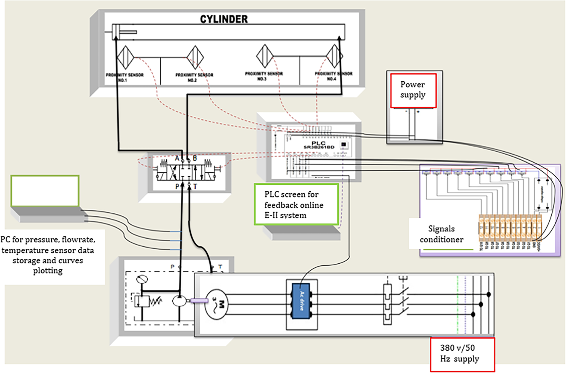
Figure 6: Schematic diagram of the closed-loop EHSS.
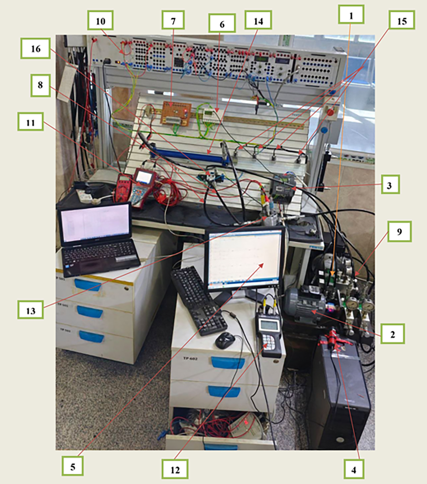
Figure 7: Closed-loop EHSS prototype setup: (1) gear pump, (2) three-phase IM, (3) AC drive (VFD), (4) tachometer, (5) PLC software, (6) PLC smart relay, (7) DC signal conditioner, (8) hoses, (9) reservoir, (10) hardware control circuit, (11) multisystem 5060 plus, (12) parker service master easy, (13) flow/pressure/temperature sensors, (14) cylinder, (15) proximity switch, (16) proportional control valve.
In the experimental closed-loop EHSS prototype setup, the tested element is the Group1, XV-1P, Series XV fixed-displacement gear pump with a displacement of 2.6 cm3/rev, as well as the maximum and peak pressures 250 and 300 bar (1) driven by the IM type BS5000 three-phase from England Bristol Company. It is an IM type squirrel cage with 380 V, 670 W (0.9 HP), 50 HZ, star connection, class B and is designed to withstand maximum operating temperatures of 55°C (2) fed by variable frequency drive (VFD), new siemens generation VFD-type (sinamics V20) used is frame size B (FSB) with a single fan (3). The use of this type of AC drive makes it possible to assess a hydraulic pump for a wide range of speeds. The rotational (rotor)speed of the pump is measured by a resolver installed on the motor shaft by using a tachometer sensor to control the rotational speed of K-SCRPM-220 (4).
The VFD is connected to the PLC programming interface (5) and the PLC compact smart relay (6) with the DC signal conditioner (7) via the appropriate exit and inputs. The gear pump ports are connected to the system using flexible hoses (8) to isolate vibrations, and the hydraulic oil reservoir (ISO 68) with a temperature sensor probe was used to measure the temperature of the hydraulic oil in the hydraulic tank (9). The rest of the system, connected with rigid steel pipes, is equipped with hardware control circuit (10) Which consists of a DC power supply with an input voltage of 220 AC and output voltage of 24 V DC with a current of 4.5 A and (Hydrotechnik (11) and Parker (12) as DAQ system) measuring components with Intelligent Sensor Detection System (ISDS) is a popular option for Hydrotechnik test sensors. These include the QG-100 flow meter with a flow range of 0.2–30 (l/m), the PR400 pressure sensor with a specification of high accuracy and high speed (10 kHz transmission rate) with a 4–20 mA output, and the TE100 screw-in temperature sensor (13), which was used to measure the temperature of the hydraulic oil in the pipes. Indeed, installed in any direction, it measures directly in the medium and produces extremely precise readings. It was placed near the suction line of the pump and close to the single-rod double-acting hydraulic cylinder, Rexroth, R961003495 (14). Furthermore, all sensors are connected to a multisystem 5060 Plus, where the pressure is displayed on its screen as well as via a software program (HYDROcom6) on the computer screen as a curve with four proximity switch model R961003106 (15), used to control the position of the cylinder.
Model 167083 proportional valve (servo valve) with high-performance range, 4-Way, 3-Position, Festo Didactic Company (16) is used as a flow rate adjuster in the system. It is connected to the digital output of the PLC smart relay for operation.
2.4.2 PLC Operational Principle
The PLC is an industrial computer that has been ruggedized and adapted for the control of manufacturing processes, such as assembly lines, machines, robotic devices, or any activity that requires high reliability, ease of programming, and process fault diagnosis. In the current work, 10 discrete inputs were programmed in PLC, divided into two on/off inputs (I1, I2), four proximity switch inputs (I3, I4, I5, I6), three speed inputs (I7, I8, I9) that must be prepared from the AC drive (VFD), and a reset input (IA). In fact, the output has six states, divided into four (Q1, Q2, Q3, Q4) that give a signal to the VSD to prepare the required speed for the IM and two (Q5, Q6) to give a signal to the proportional directional control (PDC) valve to control the direction of the cylinder movement according to the work requirements. There are 8 relay coils from input to output and counter relays, which are M1, M2, M3, M4, M5, M6, M7, and M8. So, Table 3 shows the operation of each symbol mentioned. Fig. 8 block diagram description of PLC and Software.
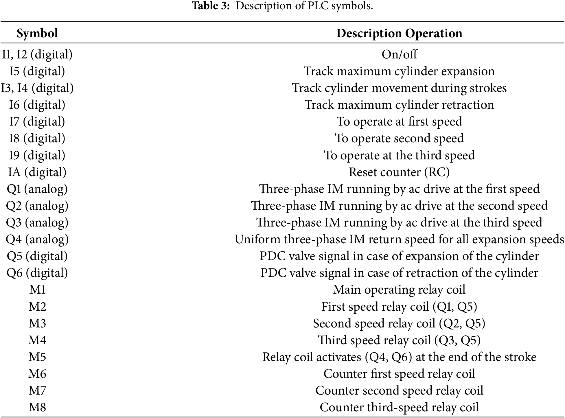
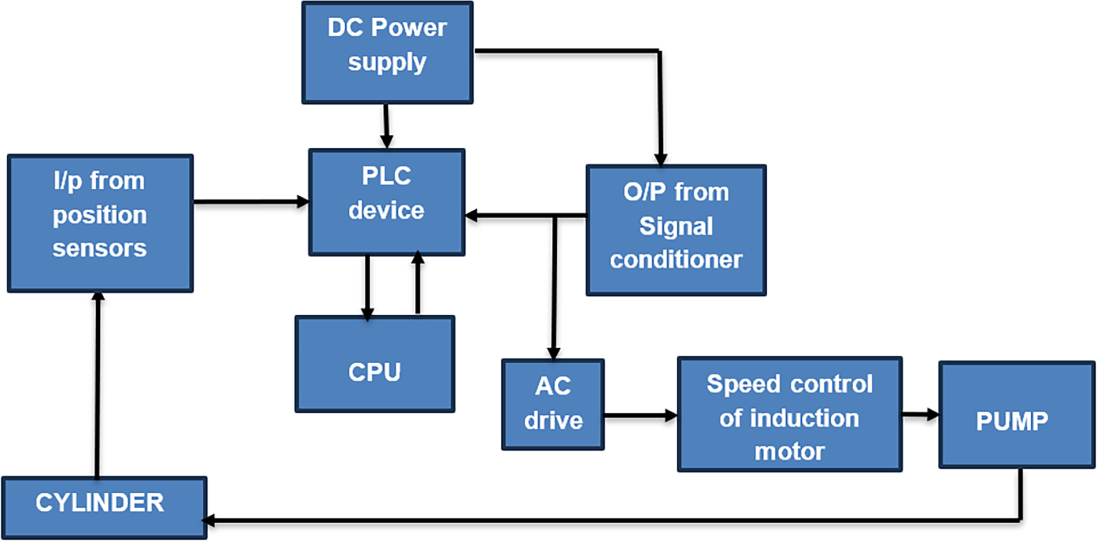
Figure 8: block diagram of PLC and software.
In the closed-loop EHSS simulation case study, a three-phase IM was controlled using the SVM control method in conjunction with the PI tune and variable frequency drive (TPI-VFD) methodology. Moreover, applying for the TPI-VFD-SVM has several advantages over other controllers, including simple control and the ability to create a simple mathematical model of the plant. In addition to this, the findings showed that the TPI-VFD-SVM methodology improves the control in terms of the starting current of the IM. Fig. 9A shows how the current and velocity curves change under different management strategies throughout the transition until stability is achieved. When the TPI-VFD-SVM approach is used in the transition stage, the starting current stabilizes around 18 A, before the current stabilizes at 13 A. So, this in turn improves the motor from the harmful effects of drawn currents and improves its performance, which will improve the performance of the motor and the hydraulic system in general. Note that the low starting current of the TPI-VFD-SVM technique is essential. The motor is shielded from the risk of high starting current by lowering the starting current. Motor behavior deteriorates as a result of these harmonics, damaging the control system and affecting the complete functionality of the EHSS.
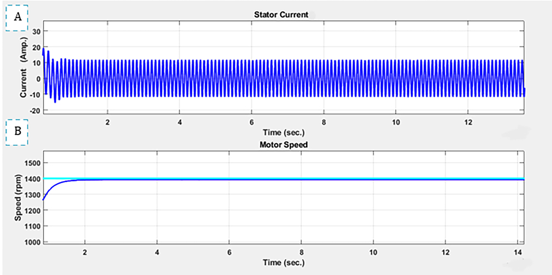
Figure 9: Dynamic response of motor current and speed for TPI-VFD-SVM control technique.
Fig. 9B illustrates that the IM’s speed in the TPI-VFD-SVM is stable, regular, oscillates without overshooting, and is equal to 1400 rpm (146.5 rad/s) in the transitional period, in accordance with the source speed that was provided, which was 1400 rpm. The result of the direct correlation between flow rate and speed.
This results in a regular flow of 6 × 10⁻⁴ m3/s, as indicated by the flow rate curve in Fig. 10C, and a decrease in pressure disturbance, which lowers the pressure drop and enhances the overall performance of the electro-hydraulic servo system, resulting in greater energy savings, as indicated by the pressure curve in Fig. 10B. The speed curve in Fig. 10D was previously explained in the discussion of Fig. 9B.
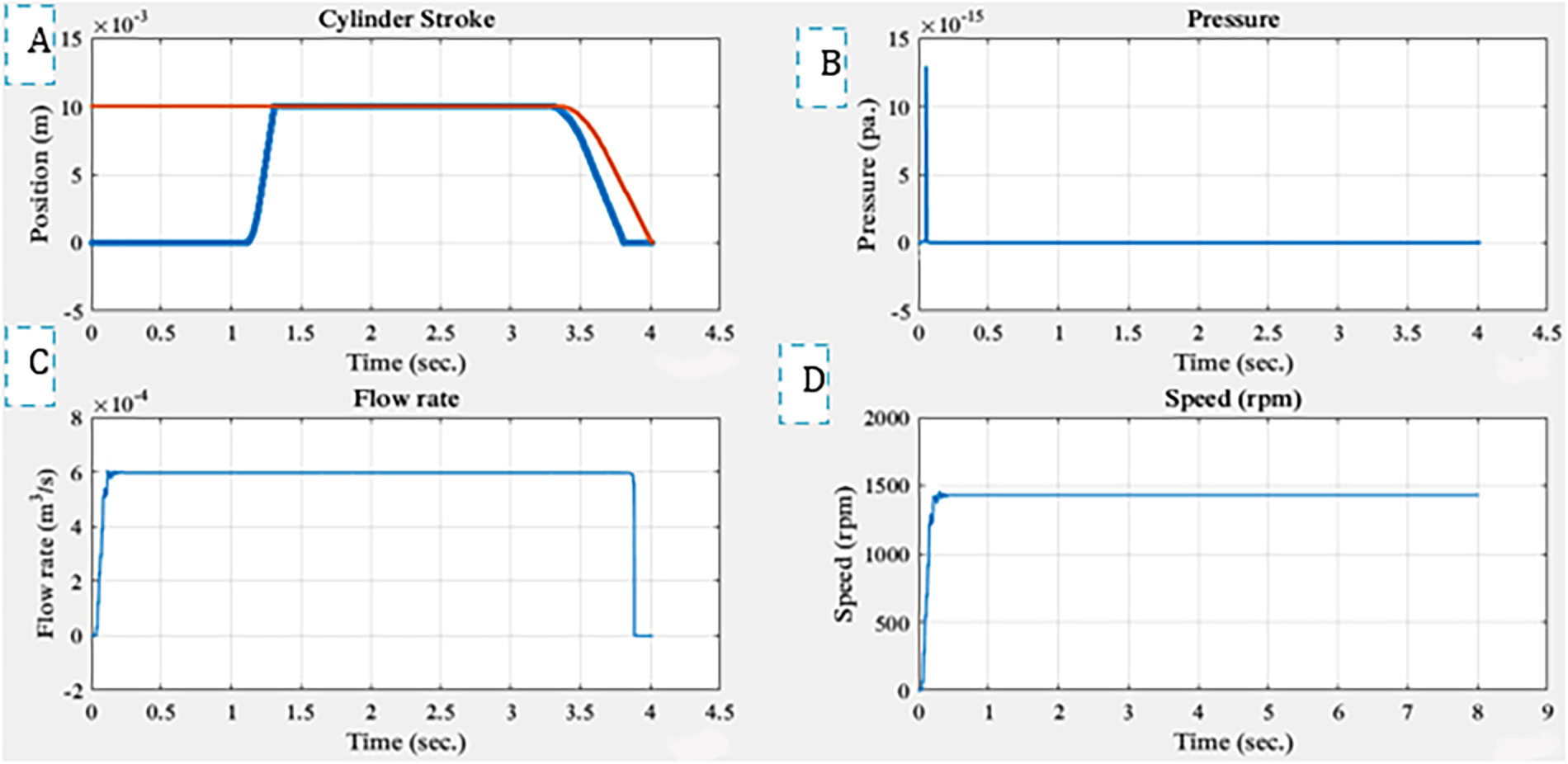
Figure 10: EHSS performance using TPI-VFD-SVM control.
At a pressure of 50 bar, the information from the position sensors indicated that the cylinder stroke’s expansion and retraction durations were 3.75 and 3.55 s, respectively. Because the piston area changes between strokes, the time required for the expansion and contraction strokes varies. The cylinder stroke is shown in Fig. 10A. The control techniques and their response appear in Table 4.
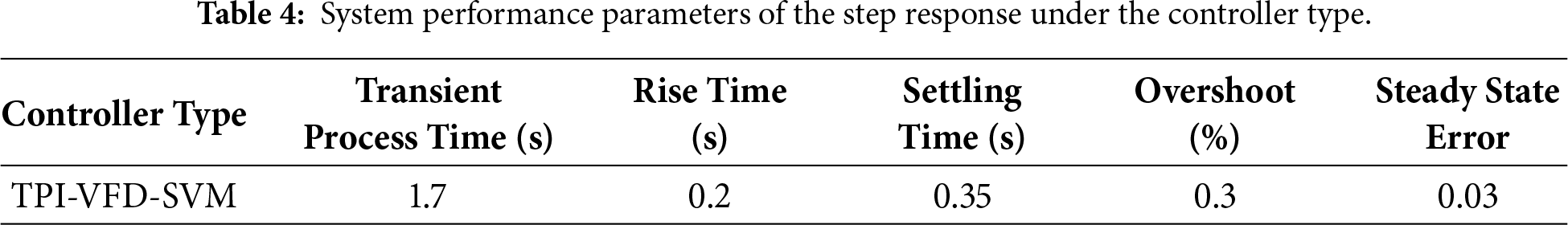
The steady-state error is extremely minimal at 0.03 for TPI-VFD-SVM, according to the data shown in Table 4. The control approach (TPI-VFD-SVM) takes less time to reach a steady state. Thus, the TPI-VFD-SVM control method has a settling time of 0.35 s. While the current study using TPI-VFD-SVM provides the lowest settling time by a value of 0.35 s to reach the lowest possible steady-state error of 0.03 with the lowest overshoot of 0.3%. Okeke and Okonkwo [15] using the FLPID reached an overshoot of 0.69%, a settling time of 2.96 s, and a steady-state error of 0.1. The comparison clearly shows the superiority of the control method used in the present study. In another work, Prasetia and Ramadani [16] suggested a PID controller, which is most often used in the field of control systems. The motor speed response had a rising time of 2.2 s and a settling time of 2.7 s. However, this method was used to reduce drawbacks associated with controllers, such as overshoot and settling time, but did not reach the optimum value in comparison with the present study, which has proven its superiority through the results.
The required steady-state stabilization time of an IM is one-quarter of the steady-state time of an uncontrolled motor. So, the settling time is reduced to a quarter of the previous value with the presence of control over the IM connected to a hydraulic system. Because the hydraulic oil is incompressible and helps in the smooth running of the IM, a smooth start and smooth stop help to reach a steady state in fractions of a second. Furthermore, the flow rate curve in Fig. 10C shows the variation of the oil flow steps at speed with very minimal overshoot. From the above explanation, it can be concluded that the higher the speed applied to the EHSS, the better the performance occurs, and more energy is saved with a more stable system. In addition, as the pressure decreases, the flow rate increases, which means an improvement of volumetric efficiency, and the current consumption of the stator becomes less, which indicates that the optimal speed of the system at 1400 rpm works better than any other speed. Therefore, it can be said that the pump speed control is better at high speeds. The results indicate the efficiency of the proposed control system and the accuracy of its performance, which achieved smooth operation of the hydraulic system and precise control of the cylinder position.
In the experimental case study, to obtain the shortest response time of hydraulic systems, the pump remains in operation even if the useful load is not applied. Pressure relief valves are often used in hydraulic systems to prevent excessive pressure. These valves are open to reroute oil flow and release excess pressure when the pressure reaches a certain limit, protecting the system from damage. To maintain effective operation and reduce excessive energy use, it is essential to balance the pressure needs. So, in experimental work, the manual AC drive was used to control the speed of the three-phase IM to suit the requirements of the load on the cylinder. The load applied to the cylinder was a mass of 20 kg, and the speeds capable of driving the load for a full stroke during the expansion and contraction of the cylinder within 40 cm of the cylinder stroke length. The three speeds were 1089.26, 1255.7, and 1325.3 rpm at frequencies of 38.5, 44.3, and 46.6 Hz and AC voltage 290.64, 335.7, and 354.16 V. The use of an AC drive has led to saving the IM power and thus saving energy according to the load requirements. The original power was 670 W, which became 532 W at 1325.3 rpm, 481 W at 1255.7 rpm, and 356 W at 1089.26 rpm. These values achieved the required purpose, but with varying volumetric efficiencies; nevertheless, the performance of the system improved and became more stable. The values of the volumetric efficiencies became sequential from the lowest speed to the highest speed, which are 88%, 91.8%, and 92.8% after the pump and 84.7%, 88.8%, and 90% before the cylinder.
EHSS uses a closed-loop system to control the three-phase IM at the desired speed according to the load requirements and drives the EHSS through PLC programming. In this case, the three speeds of the AC drive were used, with the addition of a common fourth speed when reversing in the cylinder contraction stroke. Speed control relies on feedback signals coming from position sensors rather than the user’s hand. The system will be more accurate, have a high volumetric efficiency, and the flow will be high while the pressure will be low. The drive to reduce the vibration of the IM in particular and the system as a whole in general is noticeable, which also leads to a reduction in noise and a quieter working environment. As a result of the above, the pressure has become more stable because the required load condition has been met, leakage has decreased, and the quality of hydraulic oil flow through the system has improved.
At an input frequency of 38.5 Hz, the first speed of the V/f drive programmable logic controller (VFD-PLC) is 1089.26 rpm in the expansion stroke, and the common speed retraction stroke is 1070.4 rpm. Fig. 11 shows the flow values of 2.67 LPM after the pump at 5.2 bar and 2.62 LPM before the cylinder at 4.6 bar. Fig. 12 demonstrates the pressures after the pump and before the cylinder.
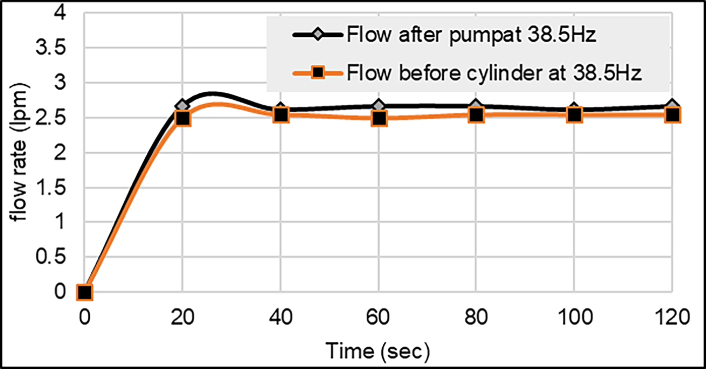
Figure 11: Flow after pump and before cylinder at 38.5 Hz.
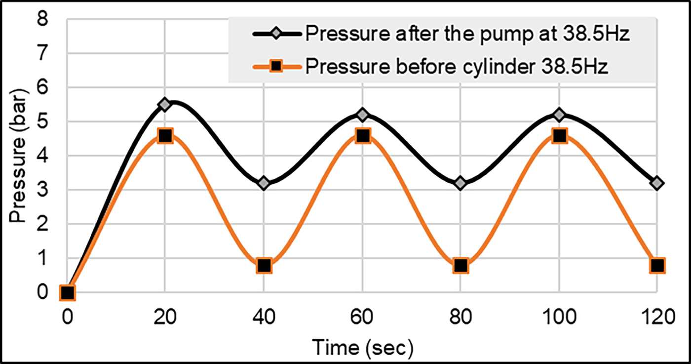
Figure 12: Pressure after the pump and before the cylinder at 38.5 Hz.
It is noted that the pressure and flow rate drop to the lowest value because motor speed is at its lowest level; the flow rate is considered high compared to the manual driving case, resulting in a high volumetric efficiency of up to 94% in the pump and 92.5% in the cylinder.
For a driven frequency of 44.3 Hz and motor speed of 1255.7 rpmin the expansion stroke and the common speed retraction stroke of 1070.4 rpm, from Fig. 13, it is seen that the flow value is equal to 3.16 LPM after the pump at 6.5
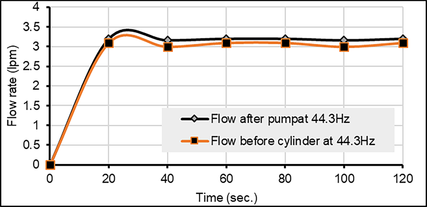
Figure 13: Flow after pump and before cylinder at 44.3 Hz.
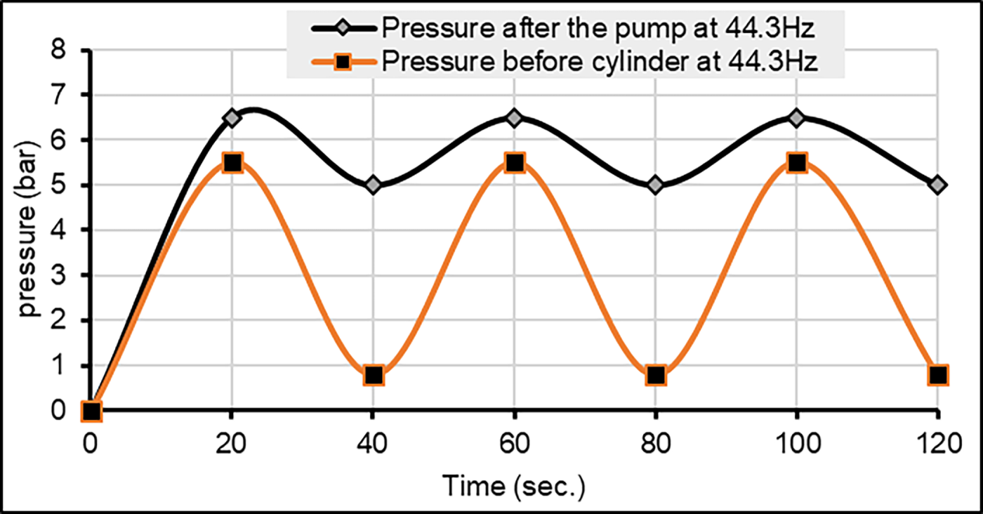
Figure 14: Pressure after the pump and before the cylinder at 44.3 Hz.
As a result of the above, increasing the speed in the second case leads to an increase in pressure and thus an increase in the flow rate. Thus, the volumetric efficiency increased, as its value became 96.7% at the pump and its value was 95% at the cylinder, leading to increased system stability, lower vibration and noise, and thus lower hydraulic oil transmission energy losses. This is clearly evident in the convergence of the volumetric efficiency values.
The last case of control is VFDPLC with feedback at driving frequency of 46.6 Hz and speed of 1325.3 rpm in expansion stroke, and the common speed retraction stroke of 1070.4 rpm. Fig. 15 shows the flow values, 3.4 LPM after the pump at 7 bar and 3.32 LPMbefore the cylinder at 6.2 bar. On the other side, Fig. 16 demonstrates the pressure after the pump and before the cylinder.
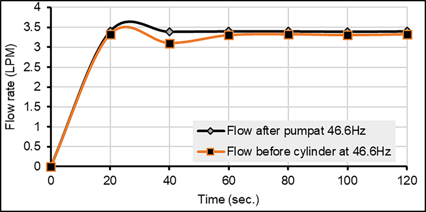
Figure 15: Flow after pump and before cylinder at 46.6 Hz.
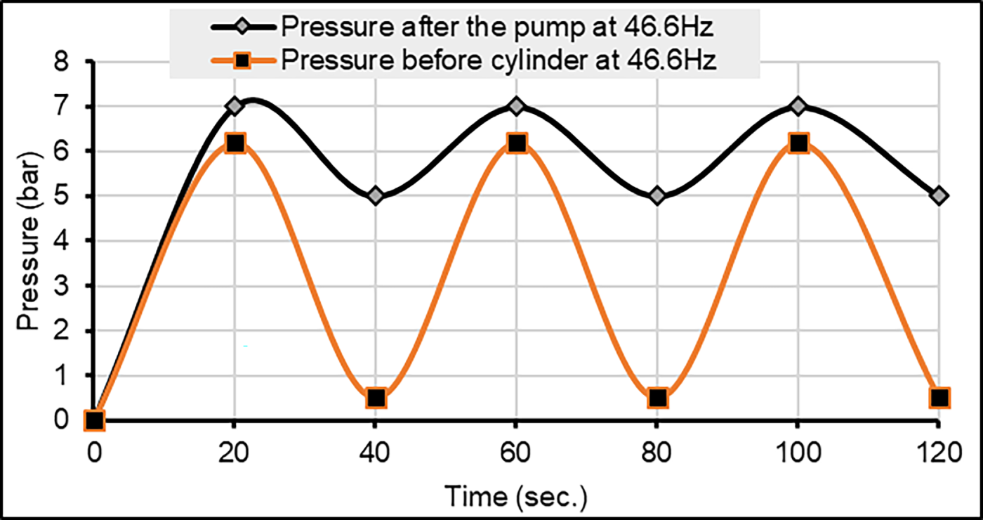
Figure 16: Pressure after the pump and before the cylinder at 46.6 Hz.
Increasing the speed of the motor in the latter case led to an increase in pressure and thus an increase in the flow rate. As a result, the volumetric efficiency increased so quickly when applying the improved closed-loop control system (VFDPLC) that its value became 98.6% at the pump and 96.3% at the cylinder. It was observed that the EHSS is stable, and vibration and noise are reduced to a minimum, thus reducing energy loss in hydraulic oil transmission. This is clearly evident in the convergence of volumetric efficiency values. In the improved EHSS, two speeds were used simultaneously: a speed on the expansion stroke and a combined speed on the contraction stroke of the hydraulic cylinder was 1070.4 rpm. This technique increased the efficiency of the system and improved its performance, as it led to saving electrical power to the motor by 48% at the return speed (contraction stroke), where power supplied to the return speed of the IM was 342.26 W.
While the current study saves more energy (20.6%, 28.25%, and 46.9%) at the speeds employed, with commonly saved motor power by 48% without any detrimental harmonics, Andrade-Cedeno et al. [14] caused greater harmonic distortion compared to the energy saved (between 28% and 49%). However, Andrade-Cedeno et al. employ a variable displacement pump in addition to the fixed displacement pump, which is more costly in terms of system elements, whereas the current work simply uses a fixed displacement pump with an induction motor. The stability of the pressure curves at the pump and the cylinder is clearly demonstrated. This indicates the accuracy of the proposed VFDPLC control technology and the quality of the EHSS, as well as excellent feedback. As a result, the system enjoys a high degree of protection and safety, which makes its lifespan long and its performance conforms to international industrial specifications. It is clearly demonstrated that the energy losses of transferring the liquid from the pump to the cylinder were reduced. As a result, the volumetric efficiency values in the pump have converged with their counterparts in the cylinder. Figs. 17 and 18 show the percentages of volumetric efficiencies at the pump and the cylinder, respectively, with rpm speed provided by the IM for all EHSSs whose curves were discussed.
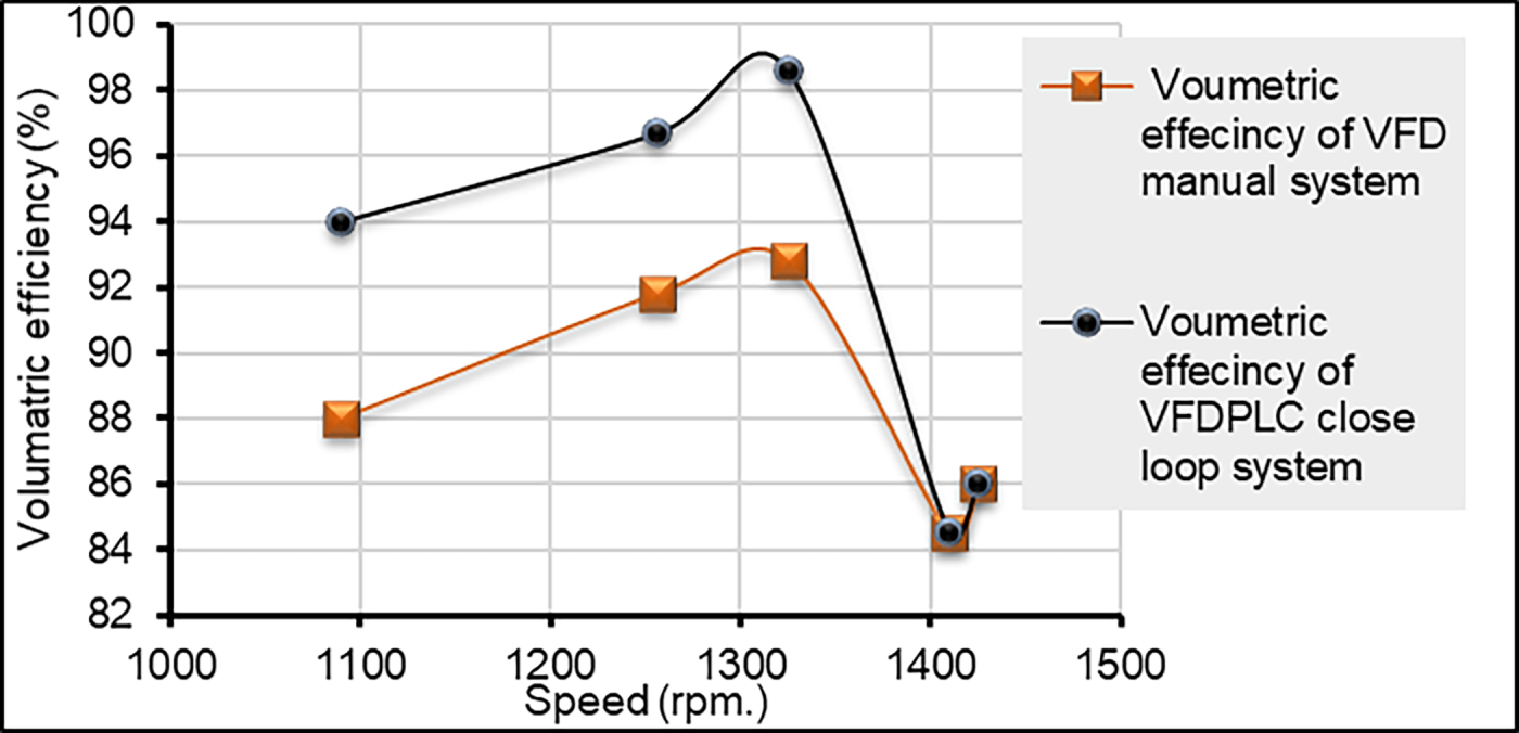
Figure 17: Volumetric efficiency at the pump.
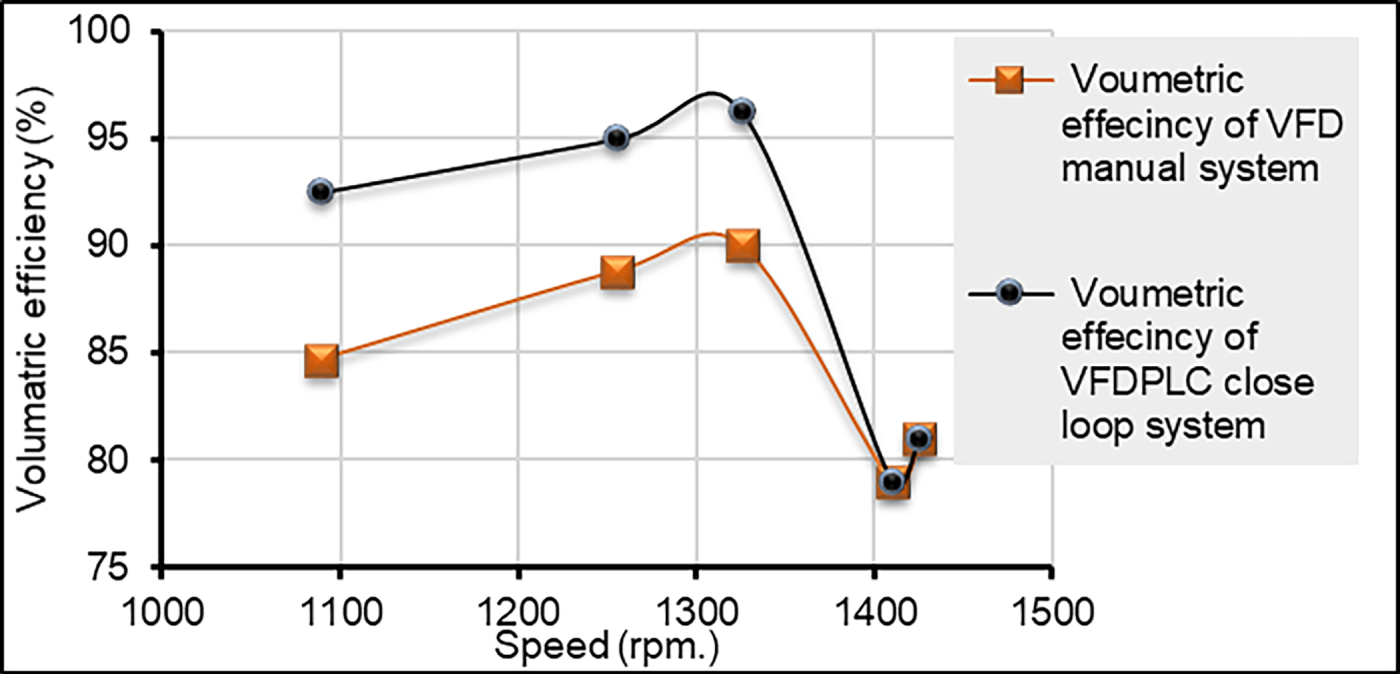
Figure 18: Volumetric efficiency at the cylinder.
The black curve in Figs. 17 and 18 show the volumetric efficiencies of the closed-loop EHS system after the pump and before the cylinder, while the red curve represents the volumetric efficiencies in the case of using the manual VFD drive after the pump and before the cylinder. Moreover, the two contact points between the curves are the efficiencies of the single-phase and three-phase IMs. It is also noted how low the efficiency of the system is if it lacks control technology.
From the three speed-pressure curves, it is also clear that the strokes over the same time in the case of closed-loop VFDPLC control are less than they were in the previous cases. This demonstrates the importance of this developed technology in implementing work requirements in a focused and proper manner and avoiding random movement or unwanted strikes that may be present in cases where there is no precise control system.
It is clear from this case that the load requirements are the most accurate, and the system matches what is desired of it in terms of performance. The load does not require repeating many strikes over the same time compared to other cases. Rather, it requires moderate repetition accuracy. Rapid strikes may cause shocks to the cylinder, which causes corrosion of the system and reduces the life of the parts, especially the moving ones. Fig. 19 illustrates the strokes of the cylinder with time for a closed-loop system controlled by the VFDPLC technique, where the time of each stroke is 38 s. This means the cylinder completed three soft and stable strokes within a given time of 120 s. While the time per stroke cylinder if a manual VFD is used is 15 s, which is less than that of the feedback control system. This means the cylinder completed eight strokes within the specified time of 120 s, but it is somewhat unstable and lacks feedback and error correction despite the presence of control technology. But with a slight improvement over the case of no drive. On the other hand, the cylinder stroke time in the case of three-phase induction motors without any control is only 12 s, meaning ten strokes in 120 s, and the movement is without controlled technology, and there is a kind of randomness in performance and an undesirable speed in the repetitions.
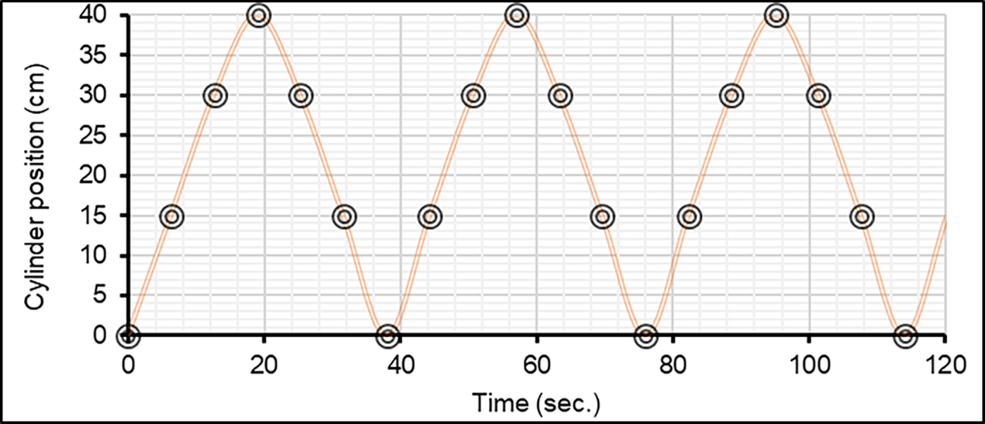
Figure 19: Closed-loop electrohydraulic servo system cylinder strokes.
Overheating may hasten component wear and cause early failure. On the other hand, excessively low temperatures may make oil thicken and raise the chance of cavitation. The lifetime and dependability of hydraulic system components are increased when the oil is kept within the prescribed temperature range.
High and low temperatures problems and the solutions mentioned are just traditional solutions implemented within the hydraulic system, but in this case of the current work, the temperatures were dealt with implicitly through the electrical control system by the AC drive controlled by PLC program (VFDPLC) to provide the required speed of the IM according to the requirements of the load applied to the cylinder. Thus, a decrease in temperatures was observed inside the system, which ranged between 27°C–27.4°C in the case of the closed-loop system and the lowest drop in the case of the manual VFD drive, in the range of 28°C–28.2°C. Also, there is a decrease in the oil temperature in the tank to 29°C due to the decrease in heat dissipation, which reduces the temperature rise in the tank, as a result of the stability of the hydraulic system parts and the decrease in temperature. Note that the room temperature for the EHSS was 20°C. Fig. 20 shows the temperature in the tank and the temperature at the closed-loop drive system.
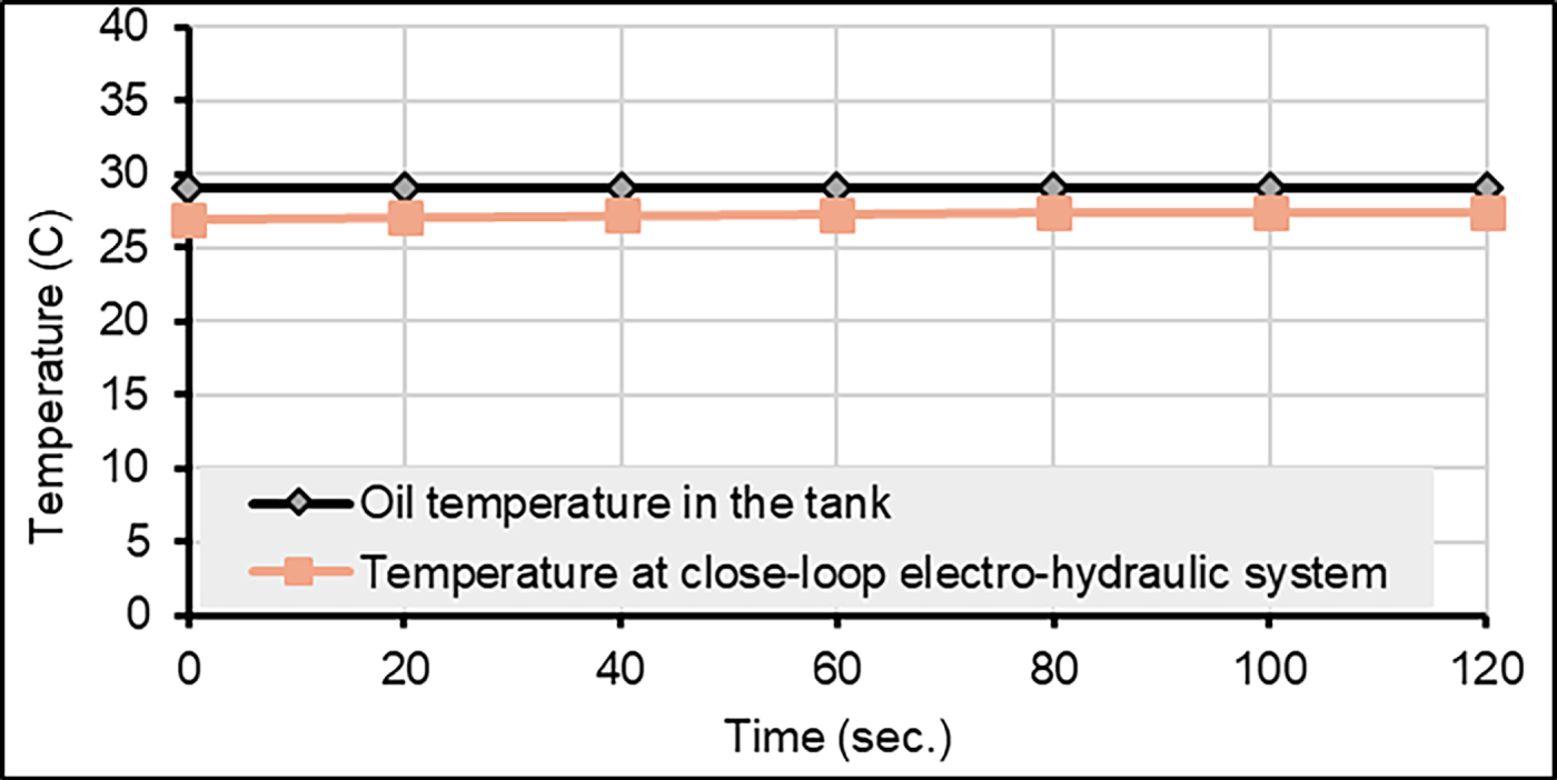
Figure 20: Oil temperature in the tank and temperature at the closed-loop electro-hydraulic system.
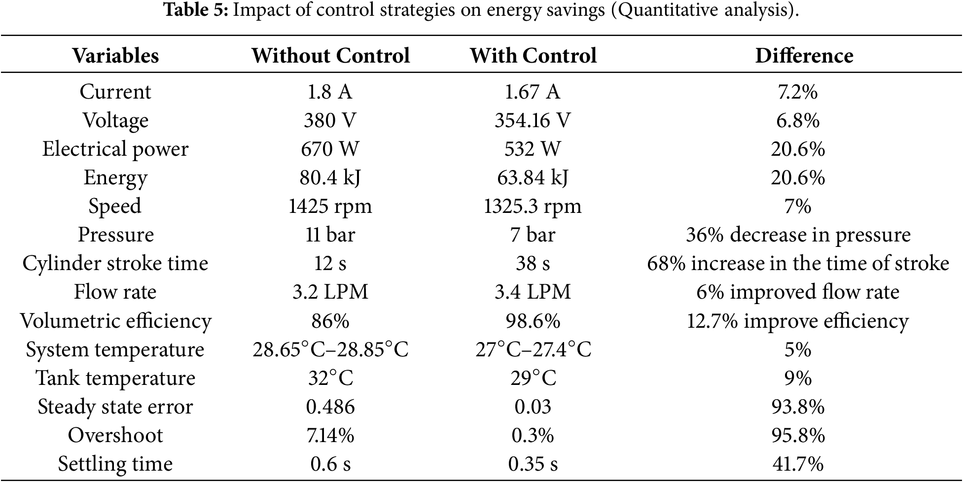
Finally, the impact of control strategies on energy savings, system stability, and volumetric efficiency is summarized in Table 5 for easier interpretation.
This paper presents a comprehensive study on developing a traditional electrohydraulic system, focusing on improving the pump’s volumetric efficiency and minimizing electrical power consumption by controlling the speed of a hydraulic pump driven by a three-phase induction motor. This approach aims to achieve optimal control of the hydraulic cylinder position (piston velocity control) using a new industrial method: VFD-PLC vector control. Indeed, design and build a practical system to achieve the best performance that matches the work requirements and loads. Moreover, the optimization of a three-phase electro-hydraulic servo system with a drive for MATLAB simulation using SVM control has been investigated. After applying the developed system, the following conclusions were drawn:
• Simulation results showed that using a tuned PI variable frequency drive space vector modulation control reduced the steady-state error to 0.03, the overshoot to 0.3%, and the settling time to 0.35 s, providing superior induction motor speed control, especially when starting with a low starting current of 18 A. In other words, it was reduced by 81% compared to the traditional system.
• The use of VFD-PLC saves motor power and thus saves energy according to the load requirement. The motor power decreased by 20.6%, 28.2%, and 46.9% compared to its rating value, at speeds of 1325.3, 1255.7, and 1089.26 rpm, respectively.
• In EHSS under VFD-PLC, two speeds were used simultaneously: a speed in the expansion stroke and a combined speed in the contraction stroke of the hydraulic cylinder. This technique has saved motor power by 48%. Thus, the power supplied to the return speed of the motor was 342.26 W.
• The best performance occurred at a speed of 1325.3 rpm under the VFDPLC closed loop system, where volumetric efficiency and flow are 3.4 and 3.32 LPM, and 98.6% and 96.3%, respectively.
• Practical experiments were used to do quantitative analysis, which was then compared with MATLAB findings. It was found that a 6% increase in volumetric flow rate led to a 12.7% increase in volumetric efficiency. A 20.6% decrease in energy and electrical power waste. All details are shown in Table 5.
Acknowledgement: My sincere appreciation goes out to the research supervisors, Drs. Jamal A.-K. Mohammed and Walaa M. Hashim, for their direction, enthusiastic support, and helpful critique of this study.
Funding Statement: The authors received no specific funding for this study.
Author Contributions: Conceptualization, Aws F. Hassan, Jamal A.-K. Mohammed and Walaa M. Hashim; methodology, Aws F. Hassan, Jamal A.-K. Mohammed and Walaa M. Hashim; software, Aws F. Hassan; experimental work validation, Aws F. Hassan, Jamal A.-K. Mohammed and Walaa M. Hashim; mathematical model analysis, Aws F. Hassan; investigation, Aws F. Hassan, Jamal A.-K. Mohammed and Walaa M. Hashim; resources, Aws F. Hassan, Jamal A.-K. Mohammed and Walaa M. Hashim; experimental data curation, Aws F. Hassan, Jamal A.-K. Mohammed and Walaa M. Hashim. All authors reviewed and approved the final version of the manuscript.
Availability of Data and Materials: The corresponding author may provide the data supporting the study’s conclusions upon request.
Ethics Approval: The research meets all applicable standards with regard to the ethics of experimentation and research integrity, and the following is being certified/declared true. As an expert scientist and along with co-authors of the field concerned, the paper has been submitted with full responsibility, following due ethical procedure, and there is no duplicate publication, fraud, or plagiarism.
Conflicts of Interest: The authors declare no conflicts of interest.
References
1. Hati SK, Mandal NP, Sanyal D. Energy-saving design of variable-displacement bi-directional pump controlled electrohydraulic system. J Syst Control Eng. 2021;235(7):1218–36. doi:10.1177/0959651820973898. [Google Scholar] [CrossRef]
2. Tsankov P, Binev I, Marazov N. Complex stand for testing of a gear pumps and investigation of the influence of the hydraulic oil temperature on the pump characteristics. Int Conf Tech Technol Educ. 2019;2019(ICTTE 2019):287–94. doi:10.15547/ictte.05.037. [Google Scholar] [CrossRef]
3. Xu M, Jin B, Chen G, Ni J. Speed-control of energy regulation based variable-speed electrohydraulic drive. Stroj Vestn J Mech Eng. 2013;59(7–8):433–42. doi:10.5545/sv-jme.2012.911. [Google Scholar] [CrossRef]
4. Dahmardeh H, Ghanbari M, Rakhtala SM. A novel combined DTC method and SFOC system for three-phase induction machine drives with a PWM switching method. J Oper Autom Power Eng. 2023;11(2):76–82. [Google Scholar]
5. Rashad L, Hassan F. Artificial neural control of 3-phase induction motor slip regulation using SPWM voltage source inverter. Eng Technol J. 2010;28(12):2392–404. doi:10.30684/etj.28.12.9. [Google Scholar] [CrossRef]
6. Ojha K, Sharma S, Tirole R. Performance analysis and speed control using indirect vector controlled for induction motor drive. Int J Tech Res Sci. 2023;8(6):18–23. doi:10.30780/ijtrs.v08.i06.004. [Google Scholar] [CrossRef]
7. Xu B, Yang J, Yang H. Comparison of energy-saving on the speed control of the VVVF hydraulic elevator with and without the pressure accumulator. Mechatronics. 2005;15(10):1159–74. doi:10.1016/j.mechatronics.2005.06.009. [Google Scholar] [CrossRef]
8. Wrat G, Ranjan P, Bhola M, Mishra SK, Das J. Position control and performance analysis of hydraulic system using two pump-controlling strategies. Proc Inst Mech Eng Part I J Syst Control Eng. 2018;233(9):1093–105. doi:10.1177/0959651818813233. [Google Scholar] [CrossRef]
9. Hashim WM, Al-Salihi HA, Hassan AF. Investigation the variation of the bulk modulus of elasticity on the performance of a conventional electrohydraulic system. J Univ Babylon Eng Sci. 2019;27(3):170–81. [Google Scholar]
10. Mohammed J, Hashim W, Beram B. Performance improvement of a conventional hydraulic elevator by using electro-hydraulic servo mechanism. Eng Technol J. 2020;38(5):748–60. doi:10.30684/etj.v38i5a.367. [Google Scholar] [CrossRef]
11. Zagar P, Kogler H, Scheidl R, Winkler B. Hydraulic switching control supplementing speed variable hydraulic drives. Actuators. 2020;9(4):129. doi:10.3390/act9040129. [Google Scholar] [CrossRef]
12. Helian B, Chen Z, Yao B. Energy-saving and accurate motion control of a hydraulic actuator with uncertain negative loads. Chin J Aeronaut. 2021;34(5):253–64. doi:10.1016/j.cja.2020.12.025. [Google Scholar] [CrossRef]
13. Duranay ZB, Guldemir H, Tuncer S. Implementation of a V/f controlled variable speed induction motor drive. EMITTER Int J Eng Technol. 2020;8(1):35–48. doi:10.24003/emitter.v8i1.490. [Google Scholar] [CrossRef]
14. Andrade-Cedeno RJ, Pérez-Rodríguez JA, Amaya-Jaramillo CD, Rodríguez-Borges CG, Llosas-Albuerne YE, Barros-Enríquez JD. Numerical study of constant pressure systems with variable speed electric pumps. Energies. 2022;15(5):1918. doi:10.3390/en15051918. [Google Scholar] [CrossRef]
15. Okeke CA, Okonkwo II. Fuzzy logic aided PID controller for induction motor speed control. Int J Adv Netw Appl. 2023;14(4):5541–8. doi:10.35444/ijana.2023.14406. [Google Scholar] [CrossRef]
16. Prasetia AM, Ramadani MN. Implementation of induction motor speed control using a PID controller. Fidel J Tek Elektro. 2024;6(1):12–20. doi:10.52005/fidelity.v6i1.195. [Google Scholar] [CrossRef]
17. Hassan A, Mohammed J, Hashim W. Modeling and control of a high-quality electro-hydraulic actuator driven via an induction motor under intelligent indirect vector control. Eng Technol J. 2024;42(8):1104–21. doi:10.30684/etj.2024.144140.1622. [Google Scholar] [CrossRef]
18. Jia W, Chen Z, Chen T, Li S. Analysis of the control characteristics of the electro-hydraulic vibration system based on the single-neuron control algorithm. Machines. 2024;12(1):58. doi:10.3390/machines12010058. [Google Scholar] [CrossRef]
19. Merritt HE. Hydraulic control systems. Hoboken, NJ, USA: John Wiley & Sons, Inc.; 1991. [Google Scholar]
20. Hassan AF, Mohammed JAK, Hashim WM. Position control of hydraulic system driven by a variable speed pump with a VFD-controlled induction motor. AIP Conf Proc. 2025;3350(1):030013. doi:10.1063/5.0297520. [Google Scholar] [CrossRef]
21. Hassan AF, Hashim WM, Mohammed JA. Effect of accumulator type on electro-hydraulic actuator performance. AIP Conf Proc. 2025;3350(1):060026. doi:10.1063/5.0297592. [Google Scholar] [CrossRef]
22. Eltoum MAM, Hussein A, Abido MA. Hybrid fuzzy fractional-order PID-based speed control for brushless DC motor. Arab J Sci Eng. 2021;46(10):9423–35. doi:10.1007/s13369-020-05262-3. [Google Scholar] [CrossRef]
Cite This Article
 Copyright © 2026 The Author(s). Published by Tech Science Press.
This work is licensed under a Creative Commons Attribution 4.0 International License , which permits unrestricted use, distribution, and reproduction in any medium, provided the original work is properly cited.
 Downloads
 Citation Tools