
 Submit a Paper
 Propose a Special lssue
 Open Access
ARTICLE

Effect of Temperature on the Performance of Proton Exchange Membrane Fuel Cell at Atomic Scales
1 Central Department of Physics, Tribhuvan University, Kirtipur, Nepal
2 Department of Physics, Patan Multiple Campus, Tribhuvan University, Lalitpur, Nepal
3 Department of Mechanical and Advance Engineering, Institute of Engineering, Pulchowk Campus, Tribhuvan University, Lalitpur, Nepal
* Corresponding Authors: Saddam Husain Dhobi. Email: ; Suresh Prasad Gupta. Email:
(This article belongs to the Special Issue: Green Energy Engineering: Optimizing Systems for Net Zero Emissions)
Energy Engineering 2026, 123(5), 6 https://doi.org/10.32604/ee.2026.076691
Received 25 November 2025; Accepted 19 January 2026; Issue published 27 April 2026
 View Full Text
 Download PDF
Abstract
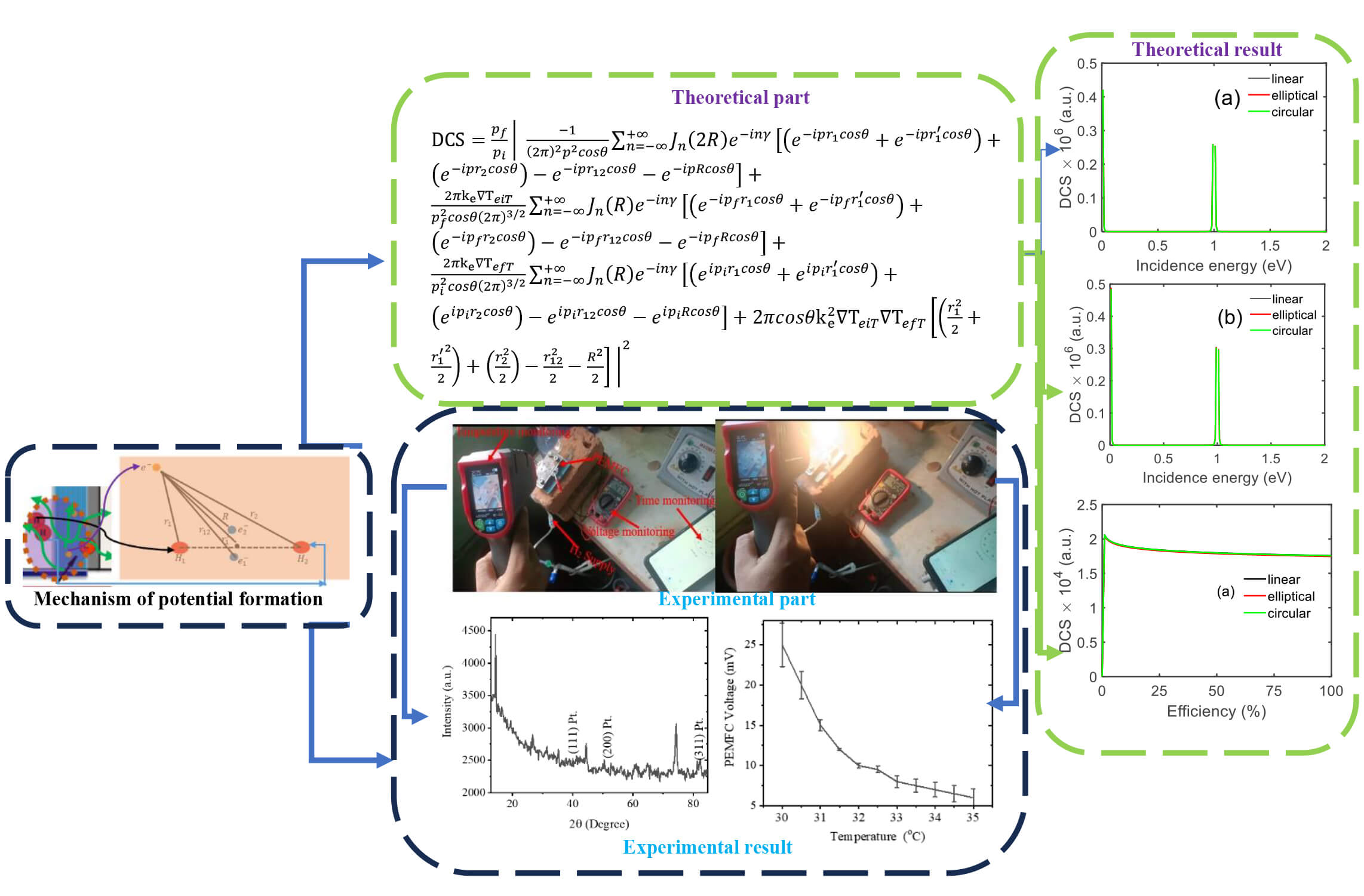
Increasing requirements on clean, efficient, and sustainable energy technologies have raised interest in hydrogen fuel cells, particularly proton exchange membrane fuel cells (PEMFCs), which are operationally characterized by high efficiency with zero emissions. The objective of this work is to study the scattering behaviors of particles participating in scattering under various conditions (energy, efficiency, temperature, cell voltage) at/around the electrode of PEMFC theoretically. For this, we developed a model using a scattering matrix, the Kroll-Watson approximation, the thermal wave function of an electron in a laser field, interaction potential, and Bessel functions to study the interaction dynamics of electrons using the differential cross-section (DCS) technique. As we are interested in studying the effect of temperature and voltage on DCS and its verification experiment. For the experiment, Pt-coated stainless-steel electrodes were prepared by electrodeposition in 1 mg Aqua Regia Pt solution at 45°C. From the solution, platinum was deposited on a 1 cm2 area of stainless steel (as an electrode) using 0.02 A current for 20 s, which is approximately 0.20 mg/cm2 with an estimated film thickness of 93 nm. X-ray diffraction was used to verify that platinum was actually deposited. A PEMFC prototype was fabricated, and hydrogen gas was fed to the prototype at 1.5 mL/min. The external heating was supplied using a 40 W filament lamp applied under a controlled environment (Audino UNO and Digital Thermostat Temperature Control). At ambient temperature, the cell voltage increased from 6 to 25 mV, but as the temperature was raised, the voltage decreased monotonically. Also, under various conditions, the DCS is effective. Results suggest that ambient temperature affects the performance of PEMFC due to an increase in disturbance of particles participating in scattering around the anode of PEMFC. This demonstrates the necessity for accurate thermal management approach to save fuel cell efficiency. This work is helpful for developing the performance and further improving the efficiency of PEMFCs based on exploration in the nature of interaction between particles at atomic scales. By connecting theoretical scattering models with the experimentally validated results, the work offers in-depth understanding of how temperature and activation potential affect fuel cell response. This knowledge is important for the design of better electrodes and thermal management strategies, which in turn will lead to more reliable and efficient clean energy systems.Graphic Abstract
Keywords
The hydrogen fuel cell technology has achieved significant attention worldwide, considering it as an alternative renewable and clean energy. Global warming, the national energy crisis, and the shortage of fossil fuels have expedited interest in renewable resources for power production. Most recent studies are dedicated to the increase of energy performance, resistance, and cost-effectiveness as well as compensating for the operational limitations of fuel cells. There are several fuel cell operation conditions; temperature is especially important for PEMFCs. It plays an essential role in the efficiency, voltage, power output, and durability of PEMFCs. Salam et al. [1] also observed that although the temperature increase favors improved device performance (and power production), it can be detrimental for membrane durability and leakage currents, underlining thus the importance of defining a suitable operational point (temperatures). Similarly, Yan et al. [2] and Cornet et al. [3] found with PEMFCs that temperature indirectly affects fuel cell performance by changing membrane humidity and water transportation in the gas diffusion and catalyst layers [4]. Fig. 1 (left) shows that when hydrogen enters (red), it reacts with the catalytic layer, producing electrons (yellow), protons (red H+), and heat, as the reaction is exothermic. Some of the inlet hydrogen remains unreacted and passes through the bottom of the anode on the left-hand side. As electrons from the bottom of the anode move upward, they generate an electromagnetic spectrum (shown in green) due to retardation. The circular inset at the bottom of the anode illustrates the system, including the spectrum (green arrow), electrons, hydrogen, and heat (purple). Our focus and assumption in this study are to investigate the scattering dynamics of electrons by hydrogen in thermal and laser fields, which are generated by the retardation of electrons on the electrode surface.

Figure 1: Microscopic mechanism of electrons formation and unreacted hydrogen in PEMFC.
The system inside the dotted circle at the bottom left is considered for this study, and similar microscopic systems are formed throughout the PEMFC. This system is a microscopic subsystem analyzed at the atomic level. Electrons and protons generated by the catalytic layer contribute to the current and voltage of the PEMFC across the external load. The current and voltage produced at this microscopic level are connected to the macroscopic behavior of the PEMFC, linking atomic-scale interactions to observable device performance.
The connection with scattering theory is as follows: electrons generated at the catalytic layer produce heat, and their retardation generates an electromagnetic spectrum. This combined system is modeled using the thermal Volkov wave function. Fig. 1 (right-hand side) illustrates the scattering theory of the assumed system.
At the electrode level, one important point of electrochemical processes occurs between electrons and hydrogen in PEMFC. Knowledge of these scattering characteristics is critical for optimizing fuel cell design and improving performance stability. The DCS, the probability of an electron scattering into a given solid angle, is essential to understanding these interactions. Several previous theoretical and experimental works have investigated the behavior of DCS at different levels. Dhobi et al. [5] to a DCS model correlating electron scattering with temperature, scattering angle, and polarization. Dhobi et al. [6] generalized this description to nonmonochromatic laser fields based on thermal Volkov solutions and showed the existence of enhanced DCS in the process of photon absorption. Dhobi et al. [7] revealed that thermal electrons show higher DCS compared to non-thermal electrons, and then destructive interference happens when a photon is absorbed.
The evolved Volkov wave functions introduced in the 1920s and used starting from the 1960s by Kroll, Watson, Baryon, and Joachain were essential to compute DCSS in scattering media. However, very recently, thermal effects have been included, and a thermal Volkov wave function has been proposed by 2024, which provides a theoretical framework to connect DCS with the current, voltage, and temperature in PEMFCs experimentally verified without including electron spin. Moreover, more general studies of electron scattering from atomic and molecular species give a reference for the PEMFC relevant interactions. Maljković et al. [8] and El idrissi et al. [9] studied complex DCS dependencies on scattering angle and incident energy, while Das et al. [10] studied silicon electron elastic scattering and reported a similar trend with angular dependence for DCS. In recent years, advanced theoretical techniques such as the Dirac partial wave approach with complex optical model potentials and semi-perturbative methods for electron–hydrogen scattering in laser fields have been used to produce accurate predictions of scattering properties [11].
Literature shows that an investigation has been carried out to date regarding the scattering behaviors of diatomic H2 molecules in laser fields and their efficiencies with operational parameters for PEMFCs. Previous research, including papers by Dhobi et al., focused on hydrogen atom interaction. This represents a major lack of knowledge regarding how electron–H2 interactions in real PEMFC conditions—which include self-induced thermal fields and laser effects (electromagnetic spectrum generated by retardation of electron)—affect the scattering behavior as well as the performance of fuel cells. Although thermal control has been demonstrated to affect PEMFC performance up to 20%–30%, it remains unexplored with respect to the electron scattering dynamics. The novelty is a relation between DCS behavior and some crucial PEMFC parameters such as efficiency, voltage, and current density at temperature. Understanding these interactions lead to optimization of charge transfer and electron transfer, which in turn improves the system’s efficiency and stability. This work is significant, as the efficiency of energy conversion in a PEMFC can reach ~90%, higher than other conventional power systems, showing that understanding and controlling electron–hydrogen scattering may have practical applications.
This work provides a comprehensive understanding of electron–hydrogen scattering near PEMFC electrodes by linking unreacted hydrogen, scattering stability, and electrochemical performance. By incorporating thermal effects, external laser fields, and quantum-relativistic spin interactions, the study offers new insights into charge transfer efficiency, energy loss minimization, and directional scattering, contributing to improved modeling and performance optimization of PEMFC systems.
A circular section of the PEMFC from Fig. 1 is considered to connect the macroscopic and microscopic perspectives for studying the scattering dynamics of electrons moving from the anode surface, as shown in Fig. 2. Fig. 2 illustrates a sketch of H2 near the anode, highlighting the scattering positions of electrons on the anode surface within a laser and heat environment. This setup focuses on studying the impact of unreacted H2 molecules near the anode on the PEMFC’s output voltage and current. Electrons generated by the reaction move from the anode surface to the external circuit, producing electric current. However, unreacted H2 molecules near the electrodes can interfere with electron movement and consequently affect the efficiency and overall performance of the PEMFC. The potential of H2 molecules in this system is estimated using Eq. (1).

Figure 2: Laser assist scattering of hydrogen molecules.
From Fig. 2,
The H2 molecule potential is employed to investigate the electron elastic scattering dynamics with H2 molecules at the surface of PEMFC electrodes. For study the scattering dynamics we used Kroll–Watson Approximation (KWA) model which provides a widely used theoretical scheme of free–free scattering processes [12]. This is because KWA is sued to study the scattering dynamics of the electron where the system is not perturbed. The consider system has represent of electron, hydrogen and proton in self-generated electromagnetic spectrum and heat. This KWA is sued to calculated the scattering matrix. This scattering matrix is sued to describe transition probabilities of electrons interacting with H2 and by differential cross-sections in thermal environment and external fields. In addition, the scattering dynamics also refer the disturbance of electrons in considered environment and its effect on PEMFC parameters. The scattering matrix is obtained as
In Eq. (2)
The generated radiation can be polarized (elliptical, circular and linear) and the vector polarization for elliptical polarization described by
where
where
here
Apply the spherical coordinate system and integrating with respective to ‘
Also putting
To study the scattering dynamics of electrons as well as the disturbance of electron by H2 is obaned using DCS as shown in Eq. (10) which is related to transition matrix relation as
By combining Eqs. (9) and (10), we obtain Eq. (11), which provides a comprehensive framework to analyze the behavior of electron by H2 molecules nearby the PEMFC anode as shown in Figs. 1 and 2.
Also, the output current of PEMFC is obtained using Eq. (2). The output current of PEMFC is due ionization of H2 at the electrode surface into electrons and protons and described by Butler–Volmer equation [13],
here, I is the current, A is the electrode surface area,
In order to validate the derived Eq. (11) experimentally and investigate the effect of the PEMFC parameters on the DCS, an experimental test was designed. For the purpose, a PEMFC electrode has been fabricated by coating platinum on stainless steel at electroplating technique.
We take 1 mg (0.001 g) of platinum and dissolved in 12 mL (0.012 L) of aqua regia to form chloroplatinic acid, the molar concentration of platinum in the solution is

Figure 3: Real experimental setup and measurement.
Computational detail: To compute Eq. (11), following parameters like electron–nucleus distances were taken as
The scattering dynamics of incidences electron (DCS) when passes nearby hydrogen located around anode is shown in Fig. 4. In Fig. 4 DCS is differential cross section whose unit atomic unit as a.u. Similar unit was considered for another figure of DCS in y-axis. Resonant contributions are observed for these electrons when passing nearby of unreacted hydrogen atoms around the electrode under various polarization states, especially at 57° scattering angle. This resonance phenomenon corresponds to an increase probability of scattering at definite energies, of electron with the vibrational or field response of hydrogen close to the electrode. The observations also reveal that the DCS increases with increasing field strength, which implies that stronger fields produce a larger quantity of charged particle generation at the PEMFC electrode. The resonance peaks in the DCS grow larger with field strength, indicating the enhancement of scattering events. For lower field strengths (see Fig. 4a) the peaks are less separated. In Fig. 4b, some deviation of the peaks is observed, indicating a field-induced modulation in scattering dynamics.

Figure 4: DCS with (a) field strength 0.001 a.u. and (b) field strength 0.1 a.u. at 57° with incidence electrons.
Fig. 5, shows the variation of the DCS with photon energy created within PEMFC as charged particle retardation at the surface of electrode under ionization of hydrogen for different scattering angles. The behaviors of the DCS decrease as increasing photon energy and later become a constant. Such behavior indicates that, in the presence of photon interacting field, incident electrons are incapable of penetrating deep inside the uncoupled target source region due to dominance source field. In addition, the photon field has a strong effect in the low energy range where both electron and photon energies are of a similar magnitude. Here, electrons and photons have a longer interaction time; field coupling is stronger, and the fields are more intense, which also contributes to higher DCS values. In opposition, with increasing photon energies the interaction time of incident electrons and photons strongly decreases.

Figure 5: DCS with photon energy scattering angle 57° with photon energy generated inside PEMFC.
Fig. 6 demonstrates that the DCS does not vary significantly with system temperature after scattering (final temperature) in all polarization cases. The maximum DCS is achieved for elliptical polarization while circular polarization follows and linear polarization displaying lowest DCS. This provides the evidence that polarization influences electron scattering with temperature [14]. More precisely, linear polarization is beneficial in terms of system temperature because the smaller DCS leads to lower scattering probability. This lower scattering leads to less electron’s forms of motion and, therefore, more an efficient free-electron flow toward small currents or towards higher tensions (voltages). As a result, choosing linear polarization at those temperatures can lead to an improvement on the PEMFC.

Figure 6: DCS with scatterer electron temperature.
Fig. 7 shows the DCS as a function of the output cell voltage, at the range of output voltage of PEMFC obtained in experiment. At low field strengths, the DCS values for each polarization condition become the same, showing that polarization does not strongly influence scattering in a weak field. However, as the field strength is increased, the DCS curves splits and become separate for various polarizations [15,16]. The DCS behaviors as a function of cell voltage presents a typical behavior: at very low voltages, reflecting the lack of scattering events due to small amount of charged particles created. Since the atom in the cell is bombarded by a certain number of hydrogens, its ionization processes create some charged particles over at the surface of electrode and scatter likelihood which gives rise to this maximum point in DCS. After this maximum, and as the cell voltage further increases, the DCS drops and finally attains an approximately constant value. This reduction indicates an enhanced efficiency of electron flow, leading to a suppression of scattering, whereas the constant value for DCS at higher voltages implies a saturated electron–hydrogen interaction.

Figure 7: DCS (a) field strength 0.01 a.u. and (b) field strength 0.1 a.u. at 5.7 degree with cell voltage of PEMFC.
Fig. 8 shows DCS increases with the active surface area of PEMFC. The linear polarization has the largest DCS, followed by circular and with elliptical polarization having the smallest. For a given activated surface area, the DCS at 1 a.u. is approximately constant. This means that there is sufficient hydrogen flow from the buffer layer, while the ionization process takes place on the electrode surface until it can no longer produce charged particles and induce an electron current. As a result, the time-dependence of electron–hydrogen coupling disappears in the non-dynamic form. For the system under consideration, elliptical polarization around the electrode exhibits superior performance compared to other types of polarizations. This is because smaller DCS indicates that it becomes less likely to scatter, and so electrons suffer fewer interferences from unreacted hydrogen between the electrode. It makes the electron transmission more effective, which results in the facilitation of larger current density and better power performance for the PEMFC.

Figure 8: DCS with reactive surface of consider PEMFC electrode.
Fig. 9 shows DCS as a function of PEMFC efficiency. The results show that at low efficiency (insurance against anything less than about 10% efficiency), the DCS increases with efficiency. Furthermore, the DCS decreases to an approximately constant. This behavior shows field strength dependent contribution to scattering dynamics; with increasing in field strength. The DCS changes with PEMFC efficiency, which means that charged particles formation and migration have impact on scattering. The steady DCS indicates that the dynamics of scattering particles become stationary. Due to same type of particles contributes in scattering and electron–hydrogen potential becomes homogeneous. Also, the electron formation intensifies, the local field around the electrode disrupt DCS. So, PEMFC can lose its efficiency. As a result, lower field strength is beneficial in obtaining the best PEMFC operation that minimizes electron–hydrogen scattering. Further increment of the field beyond this critical value can destabilize system, which causes decrease in efficiency because increases the scattering and perturbation effects of electron flow near the electrode.

Figure 9: DCS (a) field strength 0.01 a.u., (b) field strength 0.1 a.u., at 5.7 degree with efficiency of PEMFC.
X-ray diffraction of platinum coated on stainless steel (working as electrode of PEMFC) is shown in Fig. 10. Sharper and intense peak are an indication of better crystalline nature while smaller or less intense ones may be due to the smaller crystallite size and/or defects/amorphous phase within of the material at 20°, especially for 2θ. At 40° it is in line with the Pt(111), Pt(200) and Pt(311) facet of crystalline platinum [17] and at 83° it complies another crystalline phase with that conform platinum of (311). This configuration represents deposition of Pt on electrode and so this electrode can be utilized for PEMFC as the catalytic cathode for ionization of hydrogen.

Figure 10: XRD of platinum coated on stainless steel.
Following the fabrication of the prototype, a number of experiments were performed at 1.5 mL/min hydrogen. Experimental results showed that the output voltage decreases when temperature is increased [18], as illustrated in Fig. 11. To gain a better insight to this behavior, the voltage response was thoroughly examined. At the start (no external hot source), the voltage was about 0.025 V at room temperature (35°C); then, after turning-on a bulb to introduce heat into the system, the voltage decreased to 0.006 V. This whole process was repeated several times. Based on these experimental results, it was realized that the PEMFC output voltage decreases with temperature increase. This hints that the electrons produced by the hydrogen adsorption depend on temperature. The smaller the voltage, the less significant is the associated electric field. A less intense field leads to a larger distance between electrons on the anode surface so that the interaction region increases [19]. In addition, as DCS is directly related to temperature and when temperature increase voltage is lower and voltage is lower interacting distance is higher and interacting strength is lower. This means DCS is also increase with decrease voltage with increasing in temperature.

Figure 11: Output voltage with temperature.
Limitation: This study has some limitations like the theoretical model relies on approximations, such as laser-assisted scattering and thermal Volkov wave functions, which may not fully represent actual PEMFC conditions. Experimental validation is simplified due to resource constraints, lacking measurements of microscopic parameters like DCS, local temperature fields, and reaction kinetics. Voltage variations may also be influenced by proton conductivity, water management, and electrode drying, which are not captured in this work. Computational modeling uses atomic units without error bars, limiting direct comparison with experiments. The micro-to-macro connection is conceptual and partially supported numerically, and further advance experimental and theoretical studies are needed to fully validate the proposed relationships.
In this work, the DCS of electron–hydrogen collisions taking place around the electrode of a PEMFC has been systematically investigated as a function of different parameters such as incident energy, photon energy, temperature, surface area, cell voltage, and efficiency. Results demonstrate the considerable influence of DCS with respect to these parameters. The conclusions also indicate that the well-controlled conditions can improve PEMFC performance, especially for thermal balance and working stability. Theoretical calculations and the experimental validation of the model indicate that DCS is strongly dependent on the temperature as well as increases with applied bias, whereas an inverse is found between voltage and temperature. These common-sense considerations can be provided to the design and practical operation of PEMFCs for real applications. In summary, a comprehensive guideline is explored to optimize PEMFC performance by manipulating the electron–hydrogen interaction behavior.
Acknowledgement: The authors would like to thank the University Grants Commission, Nepal, for providing financial support for this work. We also extend our gratitude to the Department of Physics, Patan Multiple Campus, Tribhuvan University, for providing laboratory facilities and a conducive research environment. Special thanks are due to the Central Department of Physics, Tribhuvan University, for their kind support throughout this research.
Funding Statement: University Grants Commission, Nepal.
Author Contributions: Saddam Husain Dhobi: Identified the research problem, designed the methodology, generated computational codes, experiment and prepared the original draft of the paper. Kishori Yadav, Suresh Prasad Gupta, Jeevan Jyoti Nakarmi and Ajay Kumar Jha: Supervised the work, validated results, conducted formal analysis and reviewed the manuscript. All authors reviewed and approved the final version of the manuscript.
Availability of Data and Materials: Available on request by corresponding author.
Ethics Approval: No ethical approval needed as this work doesn’t involve any human or living organism.
Conflicts of Interest: The authors declare no conflicts of interest.
References
1. Salam MA, Habib MS, Arefin P, Ahmed K, Uddin MS, Hossain T, et al. Effect of temperature on the performance factors and durability of proton exchange membrane of hydrogen fuel cell: a narrative review. Mat Sci Res India. 2020;17(2):179–91. doi:10.13005/msri/170210. [Google Scholar] [CrossRef]
2. Yan Q, Toghiani H, Causey H. Steady state and dynamic performance of proton exchange membrane fuel cells (PEMFCs) under various operating conditions and load changes. J Power Sources. 2006;161(1):492–502. doi:10.1016/j.jpowsour.2006.03.077. [Google Scholar] [CrossRef]
3. Cornet M, Tardy E, Poirot-Crouvezier JP, Bultel Y. Impact of coolant operation on performance and heterogeneities in large proton exchange membrane fuel cells: a review. Energies. 2025;18(1):111. doi:10.3390/en18010111. [Google Scholar] [CrossRef]
4. Singla MK, Muhammed Ali SA, Kumar R, Jangir P, Khishe M, Gulothungan G, et al. Revolutionizing proton exchange membrane fuel cell modeling through hybrid aquila optimizer and arithmetic algorithm optimization. Sci Rep. 2025;15(1):5122. doi:10.1038/s41598-025-89631-8. [Google Scholar] [PubMed] [CrossRef]
5. Dhobi SH, Gupta SP, Yadav K, Jha AK. Scattering dynamics in thermal environments around PEMFC electrode. Int Energy J. 2025;25(1A):123–32. doi:10.64289/iej.25.01a05.1770929. [Google Scholar] [CrossRef]
6. Dhobi SH, Yadav K, Gupta SP, Nakarmi JJ, Jha AK. Non-monochromatic laser assist scattering in thermal environment. J Nig Soc Phys Sci. 2025;7(1):2345. doi:10.46481/jnsps.2025.2345. [Google Scholar] [CrossRef]
7. Dhobi SH, Gupta SP, Yadav K, Nakarmi JJ, Jha AK. Differential cross section with volkov-thermal wave function in coulomb potential. Atom Indo. 2024;1(1):19–25. doi:10.55981/aij.2024.1309. [Google Scholar] [CrossRef]
8. Maljković JB, Vukalović J, Pešić ZD, Blanco F, García G, Marinković BP. Experimental and theoretical study on elastic electron interaction with halothane molecule in the intermediate energy range. Eur Phys J Plus. 2023;138(4):349. doi:10.1140/epjp/s13360-023-03967-6. [Google Scholar] [CrossRef]
9. idrissi El M, Hrour E, Taj S, Manaut B. Electron impact relativistic excitation 1s − 2p of hydrogen atom. Indian J Phys. 2021;95(12):2541–51. doi:10.1007/s12648-020-01886-1. [Google Scholar] [CrossRef]
10. Das PK, Ragimkhanov GB, Khalikova ZR, Shorifuddoza M, Ashir MM, Barman J, et al. Scattering of e± by silicon atoms and transport coefficients in mixtures of inert gas with silicon vapor. Eur Phys J D. 2023;77(9):173. doi:10.1140/epjd/s10053-023-00746-x. [Google Scholar] [CrossRef]
11. Buică G. Polarization dependence in inelastic scattering of electrons by hydrogen atoms in a circularly polarized laser field. J Quant Spectrosc Radiat Transf. 2017;187:190–203. doi:10.1016/j.jqsrt.2016.09.017. [Google Scholar] [CrossRef]
12. Kroll NM, Watson KM. Charged-particle scattering in the presence of a strong electromagnetic wave. Phys Rev A. 1973;8(2):804–9. doi:10.1103/physreva.8.804. [Google Scholar] [CrossRef]
13. Noren DA, Hoffman MA. Clarifying the Butler-Volmer equation and related approximations for calculating activation losses in solid oxide fuel cell models. J Power Sources. 2005;152:175–81. doi:10.1016/j.jpowsour.2005.03.174. [Google Scholar] [CrossRef]
14. Arulsamy AD. Effect of temperature-induced electronic polarization on the scattered X-ray intensity; 2024. doi:10.2139/ssrn.4985551. [Google Scholar] [CrossRef]
15. Xu K, Lin F, Huang A, Huang M. Λ/Λ ̄ polarization and splitting induced by rotation and magnetic field. Phys Rev D. 2022;106(7):1–6. doi:10.1103/physrevd.106.l071502. [Google Scholar] [CrossRef]
16. Nagler P, Ballottin MV, Mitioglu AA, Mooshammer F, Paradiso N, Strunk C, et al. Giant magnetic splitting inducing near-unity valley polarization in van der Waals heterostructures. Nat Commun. 2017;8(1):1551. doi:10.1038/s41467-017-01748-1. [Google Scholar] [PubMed] [CrossRef]
17. Ji W, Qi W, Tang S, Peng H, Li S. Hydrothermal synthesis of ultrasmall Pt nanoparticles as highly active electrocatalysts for methanol oxidation. Nanomaterials. 2015;5(4):2203–11. doi:10.3390/nano5042203. [Google Scholar] [PubMed] [CrossRef]
18. Tang X, Zhang Y, Xu S. Temperature sensitivity characteristics of PEM fuel cell and output performance improvement based on optimal active temperature control. Int J Heat Mass Transf. 2023;206(3):123966. doi:10.1016/j.ijheatmasstransfer.2023.123966. [Google Scholar] [CrossRef]
19. Murdock D. Worked examples from introductory physics Vol. IV: electric fields. Cookeville, TN, USA: Tennessee Tech University; 2008. p. 71–85. [Google Scholar]
Cite This Article
 Copyright © 2026 The Author(s). Published by Tech Science Press.
This work is licensed under a Creative Commons Attribution 4.0 International License , which permits unrestricted use, distribution, and reproduction in any medium, provided the original work is properly cited.
 Downloads
 Citation Tools