
 Submit a Paper
 Propose a Special lssue
 Open Access
ARTICLE

Mechanical Modelling of Positive Electrode in All-Solid-State Battery Cells
1 AVL-AST d.o.o., Zagreb, Croatia
2 AVL List GmbH, Graz, Austria
3 Faculty of Mechanical Engineering and Naval Architecture, University of Zagreb, Zagreb, Croatia
* Corresponding Author: Danijel Pavković. Email:
(This article belongs to the Special Issue: Selected Papers from the SDEWES 2025 Conference on Sustainable Development of Energy, Water and Environment Systems)
Energy Engineering 2026, 123(5), 25 https://doi.org/10.32604/ee.2026.077842
Received 18 December 2025; Accepted 17 March 2026; Issue published 27 April 2026
 View Full Text
 Download PDF
Abstract
All-solid-state lithium-based batteries represent a critical evolution in energy storage, offering enhanced safety, higher energy density, and superior fast-charging capabilities. However, the integration of solid-state electrolytes introduces complex mechanical interactions at the electrode-electrolyte interface that significantly impact performance and longevity. This study introduces a cyclic plastic hardening model for ceramic electrolytes, moving beyond traditional brittle or linear-elastic assumptions. It presents a Finite Element Method (FEM) analysis of a positive electrode representative volume element (RVE), consisting of spherical Nickel-Manganese-Cobalt (NMC811) active material particles embedded in an Li7La3Zr2O12 (LLZO) solid-state electrolyte matrix, with Gaussian-distribution of particle sizes aimed to capture the stochastic heterogeneity of electrode microstructures. The simulation results illustrate the volumetric expansion and contraction of active material during lithiation and de-lithiation (electrochemical loading) cycles using a thermal expansion analogy. Due to the scarcity of cyclic plasticity data for ceramic electrolytes, the plastic hardening behavior of LLZO is approximated using a proxy material model (SiMo5 steel at 700°C) to qualitatively capture strain hardening effects. The study analyzes stress distribution, volumetric deformation, and contact evolution over five charge-discharge cycles under a uniform assembly external pressure of 10 MPa. Results indicate progressive strain hardening in the solid electrolyte, characterized by increasing tensile stresses and stabilizing volumetric deformation. Furthermore, the analysis reveals cyclic contact loss during de-lithiation, which poses risks for increased interfacial resistance. These findings provide theoretical insights into the mechanical degradation mechanisms of ASSBs, emphasizing the key role of stack pressure and material hardening in their long-term stability.Graphic Abstract
Keywords
The development of advanced battery energy storage technologies is crucial to address the growing demand for a more widespread adoption of electric vehicles [1], prolonging the autonomous operation of portable electronic devices [2], and expanding the capacity of utility grid-scale energy storage [3]. Lithium-ion batteries have emerged as the dominant energy storage technology due to their high energy density, long cycle life, and low self-discharge rate [4]. However, conventional lithium-ion batteries with liquid electrolytes also face safety concerns [4], which are related to flammability [5] and electrode dendrite growth that may eventually lead to self-discharge and possible short circuits within battery cells [6]. These issues limit their applications and may also hinder further improvements in lithium-ion technology energy density [7]. For example, some of the more robust lithium-ion battery technologies, such as lithium-iron-phosphate (LiFePO4) [8] and lithium-titanate (LTO) [9], although characterized by improved operational safety and durability due to novel anode materials and electrolyte chemistries, have much lower energy densities due to inherently lower operational voltages compared to other conventional lithium-battery technologies [10]. A broad overview of battery technologies for a wide range of applications and their characteristics can be found in [11].
Naturally, when implementing any battery technology, precise real-time monitoring of battery state-of-health [12] and operational temperature [13] is crucial for practical applications. Advanced estimation techniques combining extended and unscented Kalman filtering and state-of-the art neural networks have shown remarkable potential for accurate tracking of key battery variables. Specifically, utilization of hybrid long short-term memory extended Kalman filter (LSTM-EKF) algorithm proposed in [14] has facilitated notable reduction of noise in battery state-of-charge (SoC) estimate and dynamic tracking error, whereas the utilization of Bayesian optimization combined with long short-term memory optimization has been verified experimentally in [15] for different operating conditions and has shown significant potential for SoC estimation mean squared error reduction compared to LSTM utilization alone.
All-solid-state batteries (ASSBs), employing solid-state electrolytes (SSEs) instead of liquid electrolytes, offer a promising solution to these challenges, enabling the development of safer, more energy-dense, and faster-charging batteries [16]. Research in ASSBs has attracted significant attention in recent years due to their potential to provide significant advantages over the conventional liquid electrolyte-based lithium-ion batteries [16]. Namely, utilization of SSE eliminates the risk of liquid electrolyte leakage and its flammability, thus enhancing battery safety, while also enabling higher energy densities of ASSBs [17]. Furthermore, SSEs can potentially suppress lithium dendrite formation, a major cause of battery failure and safety hazards in conventional lithium-ion batteries [6]. Due to previously stated advantages of SSEs, extensive research efforts have been undertaken focusing on the development of novel SSE materials, optimizing electrode architectures, as well as better understanding of the complex electrochemical and mechanical processes within ASSBs [17–19].
Recent reviews categorize solid electrolytes into polymer-based, oxide-based, sulfide-based, and composite systems, noting that the selection and combination of these materials is crucial for balancing high ionic conductivity with mechanical flexibility [20–23]. To facilitate production of high-energy cathodes such as LiNi1−x−yMnxCoyO2 (NMC) along with garnet solid-state electrolytes such as Li7La3Zr2O12 (LLZO), recent study performed in [20] points out to the coating layers that stabilize interfaces and mitigate degradation mechanisms during cycling as key factors governing the materials stability. Research into single-crystal NMC (SC-NMC) cathodes presented in [24] studies structural transformations, surface layer formation, and lithium loss to provide design guidelines for robust composite cathode morphologies that minimize mechanical defects. Silicon-based and lithium-metal anodes are studied in [21,25] using multi-physics modeling to manage lithium-ion distribution, material stress regulation, and interfacial durability. Innovative dual-electrolyte architectures that combine argyrodite-type Li6PS5Cl (LPSCl) with garnet-type LLZO to ensure chemical compatibility with lithium metal anodes have been studied in [26]. The results have shown that stable cycling and high initial capacities can be achieved using such materials for ASSBs. Mathematical modeling of thin-film batteries in [27] outlines the charge transfer kinetics, diffusion effects, and migration to accurately predict thin-film battery performance. The study presented in [28] indicates that surface engineering with carbon-based primer layers significantly reduces interfacial resistance and mitigates stress accumulation, thus allowing lithium–sulfur batteries to operate efficiently even under practical low-pressure conditions. The use of soft solid-state electrolytes has also been recognized as one of key new ASSB technologies [29]. The development of solid-state battery electrolyte materials and increased safety of these safer, higher-performing alternatives to liquid-electrolyte lithium-ion technologies show significant potential for global of ASSB markets in the next decade [22], despite the current limitations of ASSB technologies indicated in [23].
However, despite the significant progress in ASSB research in recent years [30], several challenges remain to be addressed before the more widespread adoption of ASSBs can be expected, which mandates additional research in advanced materials [31] and investigating ways to scale up the existing ASSBs [32]. One of the key challenges to more widespread use of ASSBs is the relatively low ionic conductivity of many SSEs compared to liquid electrolytes [33], which can significantly limit the battery performance [34]. Additionally, the interfacial stability between the SSE and the electrode materials is crucial for ensuring efficient ion transport [35] and preventing performance degradation [36]. Finally, the mechanical behaviour of ASSBs, particularly the stresses generated during charging and discharging [37], can significantly impact battery performance and lifespan [35].
This study focuses on the mechanical modeling of the positive electrode in ASSB cells. The research presented herein introduces a cyclic plastic hardening effect for ceramic electrolytes, thus accounting for anticipated micro-scale plasticity under high external assembly stack pressure. This approach identifies a possible mechanical break-in period that would explain the initial stabilization of battery characteristics after the assembly [19]. A representative volume element (RVE) of a porous electrode filled with spherical particles of differing sizes that are characterized by normal (Gaussian) probability distribution of particle diameters is developed in this work to capture the stochastic heterogeneity of electrode material and, thus, to allow for the simulation of stress concentrations and electrode vs. electrolyte contact opening. The RVE is then appropriately meshed for the finite element simulation study. The proposed model facilitates straightforward investigation of the contact interaction between the SSE and the electrode active material, which is a critical factor influencing the mechanical behavior and performance of ASSBs. By employing finite element method (FEM) simulations using computer-aided engineering (CAE) software tools, such as Abaqus [38], Digimat [39] and Beta Ansa/Meta [40], the stresses are analyzed within the active material, solid-state electrolyte, and at the contact surfaces, along with changes in porosity, RVE volume, and total contact surface area. It should be noted that this study is solely focused on complex mechanical interactions at the active material vs. solid-state electrolyte interface, rather than developing the comprehensive multi-physical model (encompassing mechanical, thermal, and electro-chemical phenomena). By using a high-resolution FEM analysis of a representative volume element (RVE), this work is aimed at providing a baseline result for stress evolution and plastic hardening analysis within the LLZO material, which would be the basis for future research efforts.
The paper is organized as follows. Section 2 briefly outlines the structure of the all-solid-state battery cell, while Section 3 provides a detailed description of the RVE model and the FEM simulation setup. Section 4 presents the simulation results, including the analysis of stresses, strains, and contact interactions within the positive electrode, while also pointing out the limitations of the presented study. Section 5 discusses the main findings, while Section 6 summarizes the key conclusions and gives directions for future research.
2 Overview of All Solid-State Batteries
All-solid-state batteries (ASSBs) emerged as a promising alternative to conventional lithium-ion batteries by replacing the flammable liquid or gel-like electrolyte with a stable, non-volatile solid substance that has favorable properties as an ion transport medium. As shown in Fig. 1, the cathode on the left and the anode on the right are separated by a solid electrolyte layer through which lithium ions move during charging and discharging [41]. This solid medium reduces the risk of leakage while limiting the potential for thermal runaway and can potentially improve energy density and cycle life and notably reduces flammability and leakage issues while offering comparable ion transport capabilities in terms of ionic conductance [41].

Figure 1: Internal structure and operation of lithium-based all solid-state battery cell.
Electrodes within an ASSB must be compatible with the solid electrolyte and should also maintain high electrochemical performance. Traditional high-energy materials like NMC (Nickel Manganese Cobalt Oxide), LFP (lithium iron phosphate) and LCO (Lithium Cobalt Oxide) are being adapted for use in ASSBs. These materials need to maintain their structural integrity during cycling and ensure good contact with the solid electrolyte, which is critical for efficient charge transfer [42]. The solid-state electrolyte within the ASSB must combine high ionic conductivity with excellent chemical and electrochemical stability. The materials commonly used as solid electrolytes can be categorized as: (i) solid polymer electrolytes, (ii) ceramic electrolytes, and (iii) solid composite electrolytes.
Solid polymer electrolytes, such as Polyethylene Oxide (PEO), Polyacrylonitrile (PAN), Polymethyl methacrylate (PMMA), Polypropylene Oxide (PPO), are flexible and can accommodate volume changes during charging and discharging. However, their high crystallinity (such as in the case of PEO) may result in low ionic conductivity at room temperature, typically between 10−7 and 10−5 S/cm [43], which is quite low when compared to 10−1 S/cm of liquid electrolytes at the same temperature [44]. Ceramic materials, such as Li7La3Zr2O12 (LLZO) garnets, offer rather high ionic conductivity (10−3 to 10−2 S/cm [45]). Despite this, their inherent brittleness makes them prone to cracking under mechanical stress. Also, their rigidity can lead to delamination, void formation, and loss of electrode contact during cycling. Moreover, mismatched grain interfaces create high boundary resistance, thus further impeding ion transport. Composite electrolyte materials combine the benefits of ceramics and polymers, such as high conductivity (10−3 S/cm), thermal stability, and durability of ceramics with the flexibility and capability to be shaped in thin-film forms characteristic for polymers [46]. While composite electrolytes provide both structural integrity and efficient ion transport, achieving uniform particle distribution is critical, because inhomogeneity can create inconsistent ionic pathways that limit performance.
3 Finite Element Modelling of Porous Positive Electrode within All-Solid-State Battery Cell
The proposed methodology presents a Representative Volume Element (RVE) to simulate the complex micro-mechanical behavior of a positive electrode within an all-solid-state battery cell, based on a cubic domain populated with 135 spherical NMC811 particles embedded in an LLZO ceramic electrolyte matrix, using a Gaussian distribution of spherical particle sizes to capture the microstructural heterogeneity. To simulate electrochemical “breathing”, the active material is modeled as ideally elastic and subjected to virtual temperature fluctuations that drive volumetric expansion and contraction. A cyclic plastic hardening model is implemented for the LLZO electrolyte, utilizing parameters from a substitute proxy material to account for strain hardening under 10 MPa external assembly pressure.
3.1 Representative Volume Element Definition and Active Material Particle Size Modeling
Representative volume element (RVE) represents a small, statistically significant portion of the electrode that mirrors the larger material’s behavior [47]. The RVE is constructed as a cubic domain (cube) with the cube’s size that ensures that the RVE represents a realistic segment of the electrode, capturing the essential geometric and mechanical properties of the material without oversimplifying the model, while also being small enough to make the finite element analysis (FEA) computationally feasible [48].
Fig. 2 shows the RVE for the case of porous positive electrode made from NMC 811 active electrode material (80% Nickel, 10% Manganese and 10% Cobalt) and LZZO ceramic-based solid-state electrolyte, with each side of the RVE with the length of a = 26.1

Figure 2: Model of active material as spherical particles of varying sizes (a), model of solid-state electrolyte (b), and final RVE geometry with defined material domains (c).
In the process of geometry generation for the RVE, the aim is to create a stochastic particle morphology within the considered volume, mimicking the random yet structured nature of the actual material. The first step in this process is generating spherical particles of various sizes using a particle size distribution, rather than a single particle size. This is critical for accurately representing the heterogeneity of the electrode material. The stochastic particle morphology is characterized by a normal (Gaussian) statistical distribution of spherical particle diameters, which ensures that particles of different sizes are represented within the sample considered herein:
where n(x) is the Gaussian probability density function, x is the particle diameter, exp() is the natural logarithm exponential function, x0 is the mean value of active material particle diameter, and σx is the particle diameter size standard deviation.
The arrangement of these spherical particles within the cubic RVE domain is illustrated in Fig. 2, whereas the particle size normal distribution parameters (particle average diameter, variance and random generator seed) are listed in Table 1, representing the theoretical normal distribution characterized by the particle mean diameter of 5.22


Figure 3: Parameterization of NMC811 electrode active material particle diameter normal probability distribution.
However, the actual distribution of obtained sizes within the simulation may deviate from the theoretical normal distribution due to realistic variations introduced by random sampling (random generator) and the geometric constraints of the RVE. The comparative distributions of the “reference” particle size according to the normal distribution and the “actual” realistic distribution of active material particle sizes are shown in Fig. 4. The result is that active material particles having realistic size distribution have been assigned 62% of volume fraction, wherein 135 spherical particles of varying sizes have been incorporated inside the selected RVE volume.

Figure 4: Comparative representation of ideal normal distribution and actual distribution of active material particle sizes within RVE.
It should be noted, however, that while this simulation assumes a dense, perfect interface as well as idealized spherical particles and perfect phase separation to study the fundamental LZZO material stress evolution, real-life cathode composites differ significantly due to the mixing and compression of NMC and LLZO particles, which inherently introduces porosity. Unlike the idealized, fully dense contact model used here, physical electrodes contain microscopic voids and may be characterized by irregular particle packing that can act as stress concentrators or pathways for local mechanical relaxation. It should also be noted that more complex and more realistic particle morphologies may be considered to represent actual electrode microstructures instead of the “idealized” spherical shapes used in this work to further improve the accuracy of the RVE model in terms of NMC811 vs. LZZO material interaction. Even though this is beyond the scope of this work, it may be considered as one of future research directions.
3.2 Mechanical Properties of Electrode Active Material and Solid-State Electrolyte
Precise mechanical properties, including Young’s modulus (E), Poisson’s ratio (ν), and plastic hardening characteristics of both the active material and solid-state electrolyte, are vital for accurate FEM simulations of ASSB cell RVE behavior.
NMC811 active material is modeled as ideally elastic because its primary mechanical role within the RVE is to emulate the volumetric expansion and contraction (the so-called “breathing” effect), rather than to emulate the primary site of plastic deformation failure. This is justified by NMC811 material high value of Young’s modulus (E = 170 GPa), thus being significantly stiffer than other typical battery components, and allowing it to maintain structural integrity under the 10 MPa uniform stack assembly pressure and repeated cyclic loads without reaching its yield threshold in the specific simulation scenario considered herein. Furthermore, in ASSBs it is the rigidity (stiffness) of the LZZO ceramic electrolyte that represents the limiting factor for mechanical durability. Therefore, by assuming that the NMC811 is ideally elastic, the model ensures that the observed plastic hardening and stress accumulation are limited to the LLZO material, which reflects the documented failure modes, such as electrolyte cracking and contact delamination, as indicated in [49].
Elastic properties for the NMC811 active material and LLZO electrolyte were taken from literature [49–51] and are summarized in Tables 2 and 3. NMC811 (E = 170 GPa, ν = 0.30) comprises 62% of the RVE volume (Table 1). To simulate the RVE “breathing” effect during lithiation, a normalized coefficient of thermal expansion (CTE) of 1 is attributed to the NCM811 active material, modeling in this way the RVE volume changes through virtual temperature fluctuations (Table 2). On the other hand, the LLZO electrolyte (E = 150 GPa, ν = 0.26) comprises the remaining 38% of RVE volume (Table 3). The solid-state electrolyte is assigned to a zero CTE value (CTE = 0), thus reflecting its dimensional stability during cycling compared to the active material.


Mathematical modeling of plastic deformation in solid materials is conventionally formulated by means of a yield criterion, such as the von Mises formulation, and a hardening law that defines the evolution of the yield surface [52]. Hardening behavior is broadly categorized into isotropic models, where the yield surface expands uniformly in stress space, and kinematic models, where the surface translates to account for the so-called Bauschinger effect, wherein yield strength reduces in one direction after loading in the opposite direction. While linear kinematic rules provide a simplified description, nonlinear formulations such as the Armstrong-Frederick model introduce a dynamic recovery term to capture the fading memory of the material’s prior deformation dynamics [53]. The Chaboche model further refines this by superimposing multiple back-stress components, enabling a precise numerical representation of the complex, nonlinear hysteresis loops and cyclic transients [54], such as those observed in metals and advanced ceramics.
In this work, the LZZO plastic deformation and hardening behavior during cycling is described by the following model which accounts for the increased resistance to deformation after yielding (i.e., exceeding the material’s yield stress) [55]:
where dαi is the ith back stress term, dεp is the plastic strain rate, ci and γi are the material parameters related to hardening effects (see Table 4), and dp is the accumulated plastic strain rate, wherein the individual back stress terms (of N stress components) are combined into the overall stress as follows:

This model is essential for predicting the so-called “ratcheting” effect, i.e., the progressive accumulation of plastic strain under cyclic loading. By calibrating the hardening modulus ci and the recovery parameter γi across all stress components, the model can provide good prediction of plastic deformation and stress phenomena [53,54].
It should be noted that modeling of the mechanical behavior of LLZO ceramics under high external stack assembly pressure and cyclic loading can be quite complex. While generally brittle, ceramic electrolytes can exhibit micro-scale plasticity and strain hardening under specific stress states within a composite electrode [56]. Due to the absence of experimental data quantifying the cyclic plastic hardening parameters of LLZO, this study utilizes the plastic properties of SiMo5 steel (at 700°C) as a numerical proxy. Note however, that this is a hypothetical assumption, made necessary by the current lack of experimentally-supported plastic deformation and strain hardening data for LZZO ceramic, even though some recent studies point out to the necessity of identifying and quantifying these properties of LZZO material for future ASSB research [56–58]. Hence, the selection of the those parameters is not intended to provide exact quantitative stress values for LLZO, but rather to phenomenologically model the mechanism of progressive hardening and stress accumulation that occurs in materials undergoing cyclic plastic deformation. This allows for a qualitative assessment of how hardening affects interfacial contact stability over time.
The hardening behavior is implemented in Abaqus using a combined isotropic and kinematic hardening model using the following keywords: Plastic, hardening = COMBINED, data type = PARAMETERS, number back-stresses = 2. The model includes two back-stresses, thus capturing the progressive resistance of the material to deformation under cyclic loading. Table 4 lists the numerical values of parameters used in Abaqus simulation of plastic deformation and hardening of LZZO.
3.3 Representative Volume Element Meshing
RVE finite element modeling (FEM) employs precise meshing to integrate the mechanical properties of both phases. Defined contact interactions between the active material and electrolyte establish realistic boundary conditions for ASSB charge-discharge simulations. By evaluating thickness changes, electrolyte deformation, and contact surface stress, the model predicts electrode behavior during electrochemical cycling. Using Digimat [39], a conforming tetrahedral mesh was generated to ensure gap-free connectivity, i.e., to avoid electrode vs. electrolyte interfacial separation (see Fig. 5). To balance the model efficiency and accuracy, the mesh utilized a global size of 0.001, a minimum size of 0.0001, and eight refinement steps. Internal coarsening was enabled for less critical regions, while shared nodes were disabled to allow independent refinement of material zones. Curvature control with a 0.03 chordal deviation was applied to accurately represent spherical NMC811 particles, while periodic meshing was omitted due to the geometry’s non-periodicity (i.e., stochastic particle morphology represented through spherical particle size variations). The resulting mesh, generated in 39 s, comprises 780,772 elements and 194,909 nodes. The mesh fractions for LLZO (38.96%) and NMC811 (61.03%) closely align with the previously defined ratios (see Tables 2 and 3) of 38% and 62% of the total volume, wherein the slight discrepancies are due to meshing approximations designed to maintain numerical stability and computational feasibility.

Figure 5: Digimat software meshing settings (a) and final RVE meshing result (b).
The simulation file defines the contact mechanics between the NMC811 active material and LLZO solid-state electrolyte within the RVE using Abaqus [38]. The following keywords within Abaqus define the interactions between the active material and solid-state electrolyte:
• CONTACT PAIR specifies interacting surfaces, with LLZO designated as the MASTER surface (stiffer, less deformable) and NMC811 as the SLAVE surface (deforms more, undergoes volume changes).
• SURFACE INTERACTION and FRICTION define the coefficient of friction representing resistance to sliding, which is set within the model to 0.1.
• ADJUST = YES and POSITION TOLERANCE = 0.0001 ensure precise surface alignment.
• CONTACT CONTROLS with STABILIZE = 0.2 introduces viscous damping to manage rigid body motion and improve convergence, which is particularly important when considering volume changes NMC811 active material undergoes during cycling.
By applying these settings, realistic stress distribution and stable contact formulations can be ensured, thus preventing unrealistic penetrations of solid-state electrolyte or separation at the interface between the solid-state electrolyte and the active material.
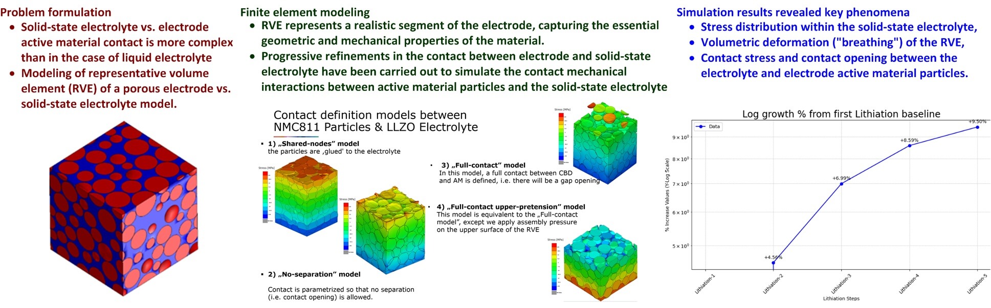
The modeling approach evolved through four progressive stages, as illustrated in Fig. 6:
1. Shared-nodes model, wherein NCM811 particles were rigidly bonded to the LZZO electrolyte. This model provided a baseline but resulted in overestimated interfacial strength.
2. No-separation model, which improved upon the result obtained by “shared-nodes” model by allowing for stress concentrations, while still preventing the separation between the NCM811 active material and LZZO electrolyte.
3. Full-contact model, which allows electrode vs. electrolyte interfacial separation between particles to form and close, thus capturing dynamic stress redistribution and potential contact loss during volume changes.
4. Full-contact upper pretension model, which incorporates a 10 MPa compressive preloading, thus simulating the external stack assembly pressure of a real battery cell, see e.g., [51].

Figure 6: Progression of development of contact models with different degrees of complexity.
3.5 Implementation of Boundary Conditions
As indicated previously, the “Full-Contact Upper-Pretension Model” is used to simulate the RVE with specific boundary conditions. Fig. 7 shows all boundary conditions applied to the RVE. All RVE surfaces, except its top surface, are fixed with zero displacement (u = 0) in all directions (X, Y, Z), thus representing the constraints of the battery housing. A 10 MPa external assembly stack pressure (pz = 10.0 MPa) is applied to the top surface along the negative Z-axis direction. This simulates the stack assembly external pressure applied during ASSB cell assembly, which is crucial for maintaining solid-to-solid contact and reducing interfacial resistance, as recommended in [51]. The bottom surface is fixed in the Z-direction (uz = 0), simulating a rigid foundation of the battery cell. Side surfaces parallel to the Y-axis and X-axis are constrained in the Y and X (uy = 0 and ux = 0) directions, respectively, thus preventing lateral movement. These constraints ensure that only the top surface is free to deform, reflecting the mechanical behavior of a tightly packed cell within its casing.

Figure 7: Implementation of all RVE boundary conditions.
This section presents the results of ASSB RVE simulations for the case of charge-discharge cycling, characterized by repeated expansion and contraction of the electrode material (so-called “breathing”). Simulations are carried out within Abaqus FEM simulation software.
4.1 Simulation Scenario and Data Processing
In order to simulate the “breathing” effect in ASSBs, this study models the cyclic expansion (lithiation) and contraction (de-lithiation) of NMC811 against stiff LLZO. These cyclic stresses can cause degradation, delamination, and contact loss which may in turn result in increased internal resistance and reduced battery capacity and overall performance. Using Abaqus, a quasi-static RVE simulation was implemented using a normalized CTE of 1 for NMC811, where temperature fluctuations drive volumetric changes. The simulation sequence (illustrated in Fig. 8) includes the following stages:
1. Assembly step that applies a 10 MPa external assembly pressure and fixes X, Y, and Z boundary nodes to simulate battery pack conditions. The 10 MPa assembly pressure (external preloading) is maintained throughout subsequent simulations steps.
2. Preparation step (pre-step), which establishes a baseline state to ensure accurate initial conditions.
3. Cycling phase, which consists of five repeated lithiation/de-lithiation cycles to analyze long-term operational effects of multiple cyclic electrochemical loading (i.e., multiple charging/discharging cycles). This final stage lasted about 80 h on a computer cluster dedicated to FEM simulations.

Figure 8: Simulation scenario phases (simulation steps).
As mentioned in Section 3.2, the simulation of repeated cyclic electrochemical loading uses appropriate virtual temperature variations, scaled by a normalized coefficient of thermal expansion (CTE), to represent lithium ions leaving or entering the NMC811 active material, thus emulating the NCM811 active material volume changes. De-lithiation, simulated by a negative temperature change, causes the contraction of active material, thus leading to interfacial separation formation and potential increased interfacial resistance. Lithiation, on the other hand, is simulated by returning the temperature to the initial value, which in turn induces expansion of active material particles, thus re-establishing contact between the NMC811 active material and LLZO solid electrolyte. These temperature changes are applied gradually using predefined amplitude profiles.
4.2 Results of RVE Phenomena Simulation Analysis
The mechanical response of the Representative Volume Element (RVE) is characterized by a vertical orientation, where the Z-axis represents the direction of both applied load and primary displacement, i.e., the displacement is specifically vertical since the top surface is the only free boundary, allowing it to move upward during lithiation-induced expansion and downward during delithiation-induced contraction. All lateral and bottom surfaces are constrained with zero-displacement boundary conditions (u = 0) to simulate the confinement of the battery housing (see Fig. 7). The reported stress values correspond to the normal interfacial stress components resulting from a 10 MPa external assembly pressure applied in the negative Z-direction (see Fig. 7) and “breathing” effect. Specifically, the CSTRESS results quantify the normal interfacial contact pressure localized at the boundaries between the NMC811 active material and the LLZO solid electrolyte, thus capturing how these interactions evolve through strain hardening across five electrochemical loading (charge-discharge) cycles.
The spatial distribution of displacements in the direction of Z-axis within the RVE during de-lithiation and lithiation processes are illustrated in Fig. 9. The detailed profiles of stresses induced by contraction and expansion of NMC811 active material within the LLZO solid-state electrolyte are shown in Figs. 10–13. Stress distribution within the solid-state electrolyte was analyzed during cyclic electrochemical loading. During de-lithiation (Fig. 10a), active material contraction induces both tensile (positive stress) and compressive (negative stress) behavior of the active material (red zones in Fig. 10a), with intermediate stresses (yellow/green) in less deformed areas. Lithiation causes active material expansion, resulting in more uniform stress distribution. However, localized tensile stress hotspots (red areas in Fig. 10b) still occur, alongside regions of high compressive stress (blue regions in Fig. 10b) and regions of moderate stress (yellow/green areas in Fig. 10b). These variations highlight the differing mechanical responses of the electrolyte under cyclic electrochemical conditions.

Figure 9: Illustration of RVE active material contraction and expansion in Z-axis during cyclic electrochemical loading (de-lithiation and lithiation) process.

Figure 10: Normal interfacial stress values during de-lithiation (a) and lithiation (b).

Figure 11: Average normal interfacial solid-state electrolyte stresses.

Figure 12: Logarithmic increase of RVE’s Z-axis deformation over five electrochemical loading cycles.

Figure 13: RVE thickness changes in Z-axis direction over five electrochemical loading cycles.
The stress evolution graphs in Fig. 11 track the average tensile (positive) and compressive (negative) stress values in the direction of Z-axis across all simulation stages. Initial assembly and preparation steps exhibit moderate stresses (+9.7 MPa tensile, −10.7 MPa compressive) resulting from the external preloading of 10 MPa (Fig. 6). Throughout the subsequent cycling scenario, maximum compressive stress remains very stable (between −35.8 and −35.989 MPa), while tensile stress increases from 24.077 MPa in the first lithiation cycle to 26.365 MPa by the end of the fifth lithiation cycle. This progressive rise indicates the emergence of strain hardening and the material’s increasing resistance to deformation over time.
Fig. 12 illustrates the percentage increase in tensile stress in the direction of Z-axis relative to the first lithiation cycle, confirming plastic hardening in the LLZO electrolyte. This hardening indicates that the material becomes increasingly resistant to deformation and accumulates stress because particles do not fully recover their initial shape. Notably, the rate of stress accumulation diminishes with each cycle, suggesting that the hardening effect may eventually stabilize and stress levels may reach a finite fixed value after further electrochemical loading cycles have been completed. The aforementioned stabilization of plastic hardening suggests that after the initial settling, the battery may reach a mechanical equilibrium that limits further fatigue-induced damage. This plateauing of stress accumulation is critical for long-term battery cycle life, as it would reduce the risk of progressive electrolyte cracking and sustained interfacial delamination over prolonged cycling.
RVE volumetric “breathing” in the direction of Z-axis was assessed by tracking the top surface node displacement, with mean volumetric strain plotted across all simulation steps in Fig. 13. This analysis reveals a continuous accumulation of irreversible deformation, evidenced by progressive growth in subsequent electrochemical loading cycles relative to the first de-lithiation baseline (Fig. 14) due to LZZO electrolyte hardening. Although de-lithiation induces pronounced volume changes, each cycle results in incomplete recovery and increasing permanent deformation. Critically, the diminishing rate of this growth suggests the LZZO material would be stabilizing and adapting to cyclic loading, thus reflecting the hardening trends observed in Fig. 12.

Figure 14: Logarithmic increase of RVE’s deformation in Z-axis direction over five electrochemical loading cycles.
Contact stress (CSTRESS parameter), i.e., the localized pressure between LLZO electrolyte and NMC811 active material particles, was also analyzed within the RVE. Fig. 15a,b shows CSTRESS distribution during lithiation and de-lithiation, respectively, with values only present at contact interfaces. Fig. 16 shows the mean CSTRESS evolution across simulation steps (i.e., assembly, preparatory step, and five de-lithiation/lithiation cycles). During de-lithiation, CSTRESS decreases progressively with each cycle (from 36.85 MPa in de-lithiation step 1 to 35.77 MPa in de-lithiation step 5), as shown by the labeled peaks in Fig. 16. These results suggest that there exists some contact interface adaptation, structural rearrangement, and increased interfacial voids due to repeated contraction. During lithiation, CSTRESS increases progressively (i.e., from 10.11 MPa in lithiation step 1 to 10.84 MPa in lithiation step 5), indicated by the labeled valleys in the graph. These results point to LZZO electrolyte vs. NMC811 active material contact strengthening (progressive strain hardening) as the expanding active material re-establishes contact with the electrolyte. The above cyclic pattern reflects two key effects observed within the RVE:
1. Hardening effect, wherein lithiation causes plastic deformation and hardening at the interface, leading to residual contact stress even after unloading (increasing minimum CSTRESS).
2. Contact interface adaptation effect, wherein repeated deformation leads to a slight reduction in peak CSTRESS during de-lithiation, suggesting a diminished capacity to reach peak stress before yielding, thus potentially compromising the contact over many electrochemical loading cycles.

Figure 15: Contact stress (CSTRESS) between solid state electrolyte and active material surfaces during lithiation (a) and de-lithiation (b).

Figure 16: Average contact stress (CSTRESS) between solid electrolyte and active material.
This indicates that monitoring contact stress evolution is crucial for assessing long-term mechanical stability and preventing interfacial detachment in solid-state batteries.
Contact opening (COPEN parameter) measures the interfacial separation between the LLZO solid-state electrolyte and NMC811 active material particles, which inherently changes due to expansion and contraction during battery cycling. This has been identified in [56] as one of the key challenges in ASSB design and implementation. Fig. 17a shows COPEN during de-lithiation, where active material contraction increases the interfacial separation between LLZO and NMC811, with yellow-red regions indicating larger separations and potential forming of voids that increase interfacial resistance and reduce ionic conductivity. Fig. 17b shows that during the lithiation process, the separation at the interface between the active material and the solid-state electrolyte effectively disappears (i.e., all particles re-establish contact).

Figure 17: Contact opening (COPEN) values at the interface between solid state electrolyte and active material during de-lithiation (a) and lithiation (b).
Fig. 18 shows the graph of mean COPEN against simulation steps (i.e., assembly, preparatory step, and five de-lithiation/lithiation cycles) with percentage labels showing the change relative to the first de-lithiation cycle (de-lithiation step 1). Contact opening parameter peaks during the first de-lithiation (de-lithiation step 1). Subsequent de-lithiation steps show a decreasing trend in mean COPEN (e.g., COPEN changesby –0.18% between de-lithiation steps 1 and 5. This indicates that repeated cycling leads to closer interface contact and progressive compaction, which is linked to mechanical hardening of the solid-state electrolyte. While this improved contact could reduce interfacial resistance, excessive compaction could also induce additional stress accumulation, possibly leading to cracking or fatigue of the solid-state electrolyte. Therefore, long-term battery performance evaluation should consider both the benefits of improved contact and the risks of stress-induced damage.

Figure 18: Contact opening values between solid state electrolyte and active material.
4.3 Simulation Study Limitations
The main goal of this work was to develop a suitable methodology to develop a RVE-FEM framework for the analysis of stress/strain and solid-state electrolyte vs. active material contact phenomena, and identifying the trends related to plastic deformation of solid-state electrolyte (hardening and contract loss). The limitations of this simulation study stem from material and modeling assumptions necessary for computational feasibility.
Firstly, the plastic hardening of the LZZO solid-state electrolyte was approximated using data from a substitute material (SiMo5 steel at 700°C) due to the lack of complete LLZO cyclic loading data, as previously explained in Section 3.2. The RVE approach, while useful for micro-level analysis, uses a small volume with idealized spherical particles (albeit characterized by stochastic size distribution), potentially neglecting complexities such as more irregular particle shape, particle agglomeration, and grain boundaries.
Secondly, it is assumed that the RVE contains an idealized, fully dense microstructure, filled with randomly sized “idealized” spherical particles which notably differ from the real-world ASSB battery material characterized by far more complex particle shapes and where the mixing and compression of NMC811 and LLZO particles inherently result in residual porosity. Since these microscopic interfacial separations (voids) are omitted from the RVE model, the simulation does not account for the effect of these voids between particles as possible localized stress concentrators or sources of decreased ionic conductivity. Note that introduction of realistic porosity effects would require detailed microstructural data and substantial calibration of such a porous RVE model, which was beyond the scope of the presented work.
Thirdly, while this work created a rigorous mechanical baseline, it did not account for multi-physics couplings between thermal, chemical, and electrical phenomena, which would interact dynamically with the mechanical stresses in real battery operation. However, integrating these variables into a single FEM framework would entail extensive research and development work and would result in increased computational complexity, which is beyond scope of this work (but may serve as a basis for future research). Finally, the boundary conditions, particularly the uniform external assembly pressure, are idealized representations of the non-uniform stresses present in a real battery cell.
Furthermore, the current study considers a uniform assembly pressure of 10 MPa. While this provides insights on the fundamental RVE responses, real-world battery operation typically involves non-uniform internal pressure distributions that can significantly alter local mechanical behavior in terms of stresses and displacements. Establishing a direct correlation between the observed material hardening and actual battery performance metrics (e.g., battery capacity retention and its cycle life) requires long-term experimental testing. Such validation under real operating regimes would represent a crucial next step in ASSB research, but this is currently beyond the scope of this baseline study of ASSB mechanical effects due to the need for specialized micromechanical measurements.
Therefore, while the presented results of simulations provide helpful qualitative insights into LZZO stress evolution, contact opening, and plastic hardening, the quantitative results should be interpreted cautiously, requiring further model refinement and experimental validation.
This study employed an RVE-based FEM approach to investigate the mechanical behavior of a positive electrode in an ASSB during charge-discharge cycling. The simulations focused on key mechanical phenomena, including stress distribution within the LLZO solid-state electrolyte, volumetric deformation (“breathing”) of the RVE, and contact stress and contact opening between the LZZO electrolyte and NMC811 active material particles. The results show a complex interplay of mechanical effects. During de-lithiation, active material contraction induces tensile and compressive stress in the electrolyte, while lithiation leads to a more uniform stress distribution, albeit with localized stress concentrations. Critically, the simulations demonstrate progressive strain hardening of the LLZO electrolyte, indicated by increasing tensile stress and decreasing contact opening over successive electrochemical loading cycles. This points to a complex contact interaction and stress evolution. It should also be noted that the simulation model has reproduced the effect of LZZO electrolyte vs. NMC811 active material mechanical contact loss (interface contact opening, as indicated in Figs. 16 and 17), which has been investigated by recent experimentally studies presented in [59,60], thus indicating that this effect would play a major role in ASSB performance in terms of conductivity and effective battery capacity. This periodic loss of contact, quantified here by the COPEN parameter, implies a cyclic increase in ASSB internal resistance, and is known to also cause ASSB capacity fading [56]. Furthermore, the observed stress accumulation in the electrolyte may support failure mechanisms where mechanical fatigue leads to crack propagation, eventually severing ionic pathways [53].
While reference [58] introduces a high-fidelity image-based microstructure identification to study coupled electro-chemo-mechanical phenomena and references [59–61] demonstrate that interfacial contact loss is a primary driver of capacity fading under varying rates and temperatures, this research introduces a cyclic plastic hardening model that accounts for electrochemical loading cycles and the related initial mechanical “break-in” period of the ASSB cell. The simulation data provide preliminary quantification of the “stabilizing” effect, showing a 9.50% increase in average tensile stress over five lithiation/de-lithiation cycles, which implies that the LLZO matrix may become increasingly resistant to deformation. Furthermore, reference [61] focuses on the risks of contact loss, whereas the model presented herein anticipates an adaptation mechanism based on progressive strain hardening where the contact opening (COPEN) decreases by about 0.18% due to progressive LZZO material compaction, accompanied by a 7.2% increase in contact stress (CSTRESS) during lithiation, thus indicating a notable strengthening of the interface.
On the other hand, the trend of “stabilization” of volumetric deformation observed after five simulated electrochemical loading cycles suggests that the electrode undergoes a kind of a “mechanical break-in period”, a phenomenon also observed in electrochemical testing of solid-state battery cells [62,63]. The observed hardening, while potentially beneficial for maintaining interfacial contact, also suggests stress accumulation that could contribute to long-term degradation mechanisms such as cracking or delamination. The cyclic changes in contact stress indicate the dynamic nature of the LZZO vs. NMC811 interface, with decreasing peak stress during de-lithiation indicating adaptation and potential void formation and increasing stress during lithiation indicating contact improvements. Volumetric deformation analysis further supports the hardening hypothesis, showing a diminishing rate of increase in RVE deformation with each cycle, thus suggesting that the material could be stabilizing after a greater number of lithiation/de-lithiation cycles.
This study presented a computational investigation into the mechanical behavior of an all-solid-state battery (ASSB) positive electrode during charge-discharge cycling. A representative volume element (RVE) approach was employed, modeling the electrode as a composite structure of spherical NMC811 active material particles embedded within an LLZO solid-state electrolyte matrix. Departing from traditional brittle or linear-elastic assumptions, the primary innovation of this work is the implementation of a cyclic plastic hardening model for the ceramic electrolyte. This approach accounts for the micro-scale plasticity and strain hardening that materials such as LLZO exhibit under the high-pressure, multi-axial stress states prevalent in composite electrodes. To ensure the model captured the inherent heterogeneity of actual microstructures, a RVE framework was introduced utilizing a Gaussian probability density function to represent the stochastic nature of active material particle sizes.
The simulation results provided insights into the complex mechanical phenomena occurring within the ASSB electrode over five electrochemical loading (charge-discharge) cycles. The qualitative assessment of stress evolution identified a distinct mechanical break-in period, which has been observed in experimental ASSB cells. Key findings include significant strain hardening in the LLZO electrolyte, manifested by increasing tensile stress and decreasing contact opening (COPEN) over successive cycles. While this hardening may initially improve interfacial contact, the resulting stress accumulation suggests a pathway for long-term mechanical degradation. Analysis of contact stress (CSTRESS) revealed a cyclic pattern of adaptation and potential void formation, while volumetric deformation analysis showed a diminishing rate of RVE expansion, further supporting the material stabilization hypothesis. These findings highlight the importance of understanding the materials’ structural integrity, contact surface quality and stress evolution across different steps of simulation.
Future research should investigate compressive stress in LLZO more thoroughly, as it significantly impacts failure mechanisms alongside tensile stress. Subsequent efforts should also validate simulation results against experimental observations of interface degradation and incorporate realistic particle morphologies beyond idealized spherical representation. Advanced models should also account for multi-physics couplings (thermal, chemical, and electrical) and complex boundary conditions, such as non-uniform external assembly pressure profiles. Ultimately, experimental benchmarking needs to be carried out using custom fabricated ASSB cells subjected to electrochemical cycling and real-time mechanical monitoring.
Acknowledgement: Technical and organizational support of RVE simulations by AVL List GmbH, Graz; Austria is gratefully acknowledged.
Funding Statement: It is gratefully acknowledged that this research has been partly supported by the European Regional Development Fund under grant agreement PK.1.1.10.0007 (DATACROSS).
Author Contributions: The authors confirm contribution to the paper as follows: study conception and design: Filip Maletić and Vilim Cvenk; data collection: Vilim Cvenk and Simon Erker; analysis and interpretation of results: Vilim Cvenk, Filip Maletić and Simon Erker; draft manuscript preparation: Danijel Pavković and Mihael Cipek. All authors reviewed and approved the final version of the manuscript.
Availability of Data and Materials: Due to the nature of this research and confidentiality restrictions, participants of this study did not agree for their data to be shared publicly, so supporting data is not available.
Ethics Approval: Not applicable.
Conflicts of Interest: The authors declare no conflicts of interest.
Abbreviations
| ASSB | All solid-state battery |
| COPEN | Contact opening between active material and solid-state electrolyte particles |
| CSTRESS | Contact stress between active material and solid-state electrolyte particles |
| CTE | Coefficient of thermal expansion |
| EKF | Extended Kalman filter |
| FEM | Finite element method |
| LLZO | Li7La3Zr2O12 ceramic (solid state electrolyte) |
| LSTM | Long short-term memory (neural network type) |
| LPSCl | Argyrodite-type Li6PS5Cl compound |
| NMC811 | Nickel-Manganese-Cobalt oxide (electrode active material) |
| PAN | Polyacrylonitrile |
| PEO | Polyethylene Oxide |
| PMMA | Polymethyl methacrylate |
| PPO | Polypropylene Oxide |
| RVE | Representative volume element in FEM analysis |
| SoC | State-of-charge |
| SSE | Solid-state electrolyte |
| Variables and Parameters | |
| a | RVE cubic domain dimension (cube side length) |
| ci | Hardening modulus (material parameter related to hardening effects) |
| γi | Recovery parameter (material parameter related to hardening effects) |
| dp | Accumulated plastic strain rate |
| dα, dαi | Overall stress and ith back stress term (plastic hardening model) |
| dεp | Plastic strain rate |
| E | Young’s modulus |
| n(x) | Gaussian (normal) distribution probability density function |
| p | Stress |
| px, py, pz | Stress in X, Y and Z direction, respectively |
| u | Displacement |
| ux, uy, uz | Displacement in X, Y and Z direction, respectively |
| ν | Poisson’s coefficient |
| σx | Standard deviation of active material particle diameter |
| x, x0 | Active material particle diameter, and diameter mean value, respectively |
| X, Y, Z | Coordinate axes in Cartesian coordinate system |
References
1. Khan M. Innovations in battery technology: enabling the revolution in electric vehicles and energy storage. Br J Multidiscip Adv Stud. 2024;5(1):23–41. doi:10.37745/bjmas.2022.0414. [Google Scholar] [CrossRef]
2. Liang Y, Zhao CZ, Yuan H, Chen Y, Zhang W, Huang JQ, et al. A review of rechargeable batteries for portable electronic devices. InfoMat. 2019;1(1):6–32. doi:10.1002/inf2.12000. [Google Scholar] [CrossRef]
3. Fan X, Liu B, Liu J, Ding J, Han X, Deng Y, et al. Battery technologies for grid-level large-scale electrical energy storage. Trans Tianjin Univ. 2020;26(2):92–103. doi:10.1007/s12209-019-00231-w. [Google Scholar] [CrossRef]
4. Liu K, Liu Y, Lin D, Pei A, Cui Y. Materials for lithium-ion battery safety. Sci Adv. 2018;4(6):eaas9820. doi:10.1126/sciadv.aas9820. [Google Scholar] [PubMed] [CrossRef]
5. Arbizzani C, Gabrielli G, Mastragostino M. Thermal stability and flammability of electrolytes for lithium-ion batteries. J Power Sources. 2011;196(10):4801–5. doi:10.1016/j.jpowsour.2011.01.068. [Google Scholar] [CrossRef]
6. Rosso M, Brissot C, Teyssot A, Dollé M, Sannier L, Tarascon JM, et al. Dendrite short-circuit and fuse effect on Li/polymer/Li cells. Electrochim Acta. 2006;51(25):5334–40. doi:10.1016/j.electacta.2006.02.004. [Google Scholar] [CrossRef]
7. Etacheri V, Marom R, Elazari R, Salitra G, Aurbach D. Challenges in the development of advanced Li-ion batteries: a review. Energy Environ Sci. 2011;4(9):3243. doi:10.1039/c1ee01598b. [Google Scholar] [CrossRef]
8. Chen SP, Lv D, Chen J, Zhang YH, Shi FN. Review on defects and modification methods of LiFePO4 cathode material for lithium-ion batteries. Energy Fuels. 2022;36(3):1232–51. doi:10.1021/acs.energyfuels.1c03757. [Google Scholar] [CrossRef]
9. Sandhya CP, John B, Gouri C. Lithium titanate as anode material for lithium-ion cells: a review. Ionics. 2014;20(5):601–20. doi:10.1007/s11581-014-1113-4. [Google Scholar] [CrossRef]
10. International Renewable Energy Agency (IRENA). Road transport: the cost of renewable solutions, IRENA’s costing study. [cited 2025 Nov 16]. Available from: https://www.irena.org/publications/2013/Jul/Road-Transport-The-Cost-of-Renewable-Solutions. [Google Scholar]
11. Zhu Z, Jiang T, Ali M, Meng Y, Jin Y, Cui Y, et al. Rechargeable batteries for grid scale energy storage. Chem Rev. 2022;122(22):16610–751. doi:10.1021/acs.chemrev.2c00289. [Google Scholar] [PubMed] [CrossRef]
12. Zhang Y, Wu T, Zhang D. Method for estimating the state of health of lithium-ion batteries based on differential thermal voltammetry and sparrow search algorithm-Elman neural network. Energy Eng. 2025;122(1):203–20. doi:10.32604/ee.2024.056244. [Google Scholar] [CrossRef]
13. Costa M, Palombo A, Ricci A, Sorge U. Thermal behavior of a LFP battery for residential applications: development of a multi-physical numerical model. Energy Eng. 2025;122(5):1629–43. doi:10.32604/ee.2025.062613. [Google Scholar] [CrossRef]
14. Khemiri K, Najari M, Ferhi M, Djebali R, Bjaoui M. Enhancing state of charge estimation for lithium-ion batteries in noisy environments using a hybrid LSTM-EKF mode. In: Proceedings of the 2025 15th International Renewable Energy Congress (IREC); 2025 Feb 2–4; Hammamet, Tunisia. p. 1–4. doi:10.1109/IREC64614.2025.10926811. [Google Scholar] [CrossRef]
15. Wang S, Ma C, Gao H, Deng D, Fernandez C, Blaabjerg F. Improved hyperparameter Bayesian optimization-bidirectional long short-term memory optimization for high-precision battery state of charge estimation. Energy. 2025;328(1):136598. doi:10.1016/j.energy.2025.136598. [Google Scholar] [CrossRef]
16. Yin Z, Zhu J, Yan A, Lyu L, Jiang B, Wang X, et al. Battery management system towards solid-state batteries. Chain. 2024;1(4):319–53. doi:10.23919/chain.2024.000011. [Google Scholar] [CrossRef]
17. Zhao W, Yi J, He P, Zhou H. Solid-state electrolytes for lithium-ion batteries: fundamentals, challenges and perspectives. Electrochem Energy Rev. 2019;2(4):574–605. doi:10.1007/s41918-019-00048-0. [Google Scholar] [CrossRef]
18. He X, Bai Q, Liu Y, Nolan AM, Ling C, Mo Y. Crystal structural framework of lithium super-ionic conductors. Adv Energy Mater. 2019;9(43):1902078. doi:10.1002/aenm.201902078. [Google Scholar] [CrossRef]
19. Su H, Li P, Li R, Wang Z, Zhao X, Zhang Z, et al. Exploring the frontier: hybrid solid-state batteries manufacturing and lifespan investigation. In: Proceedings of the 2024 IEEE Transportation Electrification Conference and Expo (ITEC); 2024 Jun 19–21; Chicago, IL, USA. p. 1–4. doi:10.1109/ITEC60657.2024.10598893. [Google Scholar] [CrossRef]
20. Nolan AM, Wachsman ED, Mo Y. Computation-guided discovery of coating materials to stabilize the interface between lithium garnet solid electrolyte and high-energy cathodes for all-solid-state lithium batteries. Energy Storage Mater. 2021;41:571–80. doi:10.1016/j.ensm.2021.06.027. [Google Scholar] [CrossRef]
21. Machín A, Morant C, Márquez F. Advancements and challenges in solid-state battery technology: an in-depth review of solid electrolytes and anode innovations. Batteries. 2024;10(1):29. doi:10.3390/batteries10010029. [Google Scholar] [CrossRef]
22. Thomas F, Mahdi L, Lemaire J, Santos DMF. Technological advances and market developments of solid-state batteries: a review. Materials. 2024;17(1):239. doi:10.3390/ma17010239. [Google Scholar] [PubMed] [CrossRef]
23. Bistri D, Afshar A, Di Leo CV. Modeling the chemo-mechanical behavior of all-solid-state batteries: a review. Meccanica. 2021;56(6):1523–54. doi:10.1007/s11012-020-01209-y. [Google Scholar] [CrossRef]
24. Abraham BN, Ngasoh OF, Offia-Kalu NE, Anye VC, Amune D, Obi UC, et al. Understanding degradation mechanisms in single crystal NMC cathodes for enhanced lithium-ion battery performance—a review. In: Proceedings of the 2023 2nd International Conference on Multidisciplinary Engineering and Applied Science (ICMEAS); 2023 Nov 1–3; Abuja, Nigeria. p. 1–6. doi:10.1109/ICMEAS58693.2023.10429902. [Google Scholar] [CrossRef]
25. Gao X, Jia L, Zhang X. Interface engineering for silicon/carbon composite anode in all-solid-state batteries. Energy Mater Devices. 2025;3(3):9370067. doi:10.26599/emd.2025.9370067. [Google Scholar] [CrossRef]
26. Klimpel M, Černe C, Šivavec J, Baumgärtner JF, Zhang H, Widmer R, et al. Dual-layer Li metal all-solid-state battery based on an argyrodite-type Li6PS5Cl catholyte and a garnet-type Li7La3Zr2O12Separator. ACS Appl Energy Mater. 2025;8(21):15900–10. doi:10.1021/acsaem.5c02435. [Google Scholar] [CrossRef]
27. Danilov D, Niessen RAH, Notten PHL. Modeling all-solid-state Li-ion batteries. J Electrochem Soc. 2011;158(3):A215. doi:10.1149/1.3521414. [Google Scholar] [CrossRef]
28. Park J, Jung J, Yang S, Kim DH, Lee JB, Oh JAS, et al. Realizing low-pressure operation of all-solid-state lithium-sulfur batteries enabled by carbon-coated current collectors. Adv Energy Mater. 2026;16(1):e04272. doi:10.1002/aenm.202504272. [Google Scholar] [CrossRef]
29. Farzanian S, Vazquez Mercado J, Shozib I, Sivadas N, Lacivita V, Wang Y, et al. Mechanical investigations of composite cathode degradation in all-solid-state batteries. ACS Appl Energy Mater. 2023;6(18):9615–23. doi:10.1021/acsaem.3c01681. [Google Scholar] [CrossRef]
30. Sang J, Tang B, Pan K, He YB, Zhou Z. Current status and enhancement strategies for all-solid-state lithium batteries. Acc Mater Res. 2023;4(6):472–83. doi:10.1021/accountsmr.2c00229. [Google Scholar] [CrossRef]
31. Karuthedath Parameswaran A, Azadmanjiri J, Palaniyandy N, Pal B, Palaniswami S, Dekanovsky L, et al. Recent progress of nanotechnology in the research framework of all-solid-state batteries. Nano Energy. 2023;105:107994. doi:10.1016/j.nanoen.2022.107994. [Google Scholar] [CrossRef]
32. Lee J, Lee T, Char K, Kim KJ, Choi JW. Issues and advances in scaling up sulfide-based all-solid-state batteries. Acc Chem Res. 2021;54(17):3390–402. doi:10.1021/acs.accounts.1c00333. [Google Scholar] [PubMed] [CrossRef]
33. Sau K, Takagi S, Ikeshoji T, Kisu K, Sato R, dos Santos EC, et al. Unlocking the secrets of ideal fast ion conductors for all-solid-state batteries. Commun Mater. 2024;5(1):122. doi:10.1038/s43246-024-00550-z. [Google Scholar] [CrossRef]
34. Kerman K, Luntz A, Viswanathan V, Chiang YM, Chen Z. Review—practical challenges hindering the development of solid state Li ion batteries. J Electrochem Soc. 2017;164(7):A1731–44. doi:10.1149/2.1571707jes. [Google Scholar] [CrossRef]
35. Richards WD, Miara LJ, Wang Y, Kim JC, Ceder G. Interface stability in solid-state batteries. Chem Mater. 2016;28(1):266–73. doi:10.1021/acs.chemmater.5b04082. [Google Scholar] [CrossRef]
36. Liu J, Yuan H, Liu H, Zhao CZ, Lu Y, Cheng XB, et al. Unlocking the failure mechanism of solid state lithium metal batteries. Adv Energy Mater. 2022;12(4):2100748. doi:10.1002/aenm.202100748. [Google Scholar] [CrossRef]
37. Tian J, Chen Z, Zhao Y. Review on modeling for chemo-mechanical behavior at interfaces of all-solid-state lithium-ion batteries and beyond. ACS Omega. 2022;7(8):6455–62. doi:10.1021/acsomega.1c06793. [Google Scholar] [PubMed] [CrossRef]
38. Simulia/abaqus: general-purpose finite element analysis software, dassault systèmes. [cited 2025 Nov 16]. Available from: https://www.3ds.com/products/simulia/abaqus/cae. [Google Scholar]
39. Hexagon. Digimat: the nonlinear multi-scale material and structure modeling platform. [cited 2025 Nov 16]. Available from: https://hexagon.com/products/digimat. [Google Scholar]
40. BETA simulation solutions. [cited 2025 Nov 16]. Available from: https://www.beta-cae.com/. [Google Scholar]
41. Nanda J, Wang C, Liu P. Frontiers of solid-state batteries. MRS Bull. 2018;43(10):740–5. doi:10.1557/mrs.2018.234. [Google Scholar] [CrossRef]
42. Fraunhofer ISI. Solid-state battery roadmap 2035+. Karlsruhe, Germany: Fraunhofer ISI; 2022 [cited 2025 Nov 16]. Available from: https://www.isi.fraunhofer.de/content/dam/isi/dokumente/cct/2022/SSB_Roadmap.pdf. [Google Scholar]
43. Xue Z, He D, Xie X. Poly(ethylene oxide)-based electrolytes for lithium-ion batteries. J Mater Chem A. 2015;3(38):19218–53. doi:10.1039/c5ta03471j. [Google Scholar] [CrossRef]
44. Tarascon JM, Armand M. Issues and challenges facing rechargeable lithium batteries. Nature. 2001;414(6861):359–67. doi:10.1038/35104644. [Google Scholar] [PubMed] [CrossRef]
45. García Daza FA, Bonilla MR, Llordés A, Carrasco J, Akhmatskaya E. Atomistic insight into ion transport and conductivity in Ga/Al-substituted Li7La3Zr2O12 solid electrolytes. ACS Appl Mater Interfaces. 2019;11(1):753–65. doi:10.1021/acsami.8b17217. [Google Scholar] [PubMed] [CrossRef]
46. Vinnichenko M, Waetzig K, Aurich A, Baumgaertner C, Herrmann M, Ho CW, et al. Li-ion conductive Li1.3Al0.3Ti1.7(PO4)3 (LATP) solid electrolyte prepared by cold sintering process with various sintering additives. Nanomaterials. 2022;12(18):3178. doi:10.3390/nano12183178. [Google Scholar] [PubMed] [CrossRef]
47. Kashkooli AG, Amirfazli A, Farhad S, Lee DU, Felicelli S, Park HW, et al. Representative volume element model of lithium-ion battery electrodes based on X-ray nano-tomography. J Appl Electrochem. 2017;47(3):281–93. doi:10.1007/s10800-016-1037-y. [Google Scholar] [CrossRef]
48. Kanit T, Forest S, Galliet I, Mounoury V, Jeulin D. Determination of the size of the representative volume element for random composites: statistical and numerical approach. Int J Solids Struct. 2003;40(13–14):3647–79. doi:10.1016/S0020-7683(03)00143-4. [Google Scholar] [CrossRef]
49. Yu S, Schmidt RD, Garcia-Mendez R, Herbert E, Dudney NJ, Wolfenstine JB, et al. Elastic properties of the solid electrolyte Li7La3Zr2O12 (LLZO). Chem Mater. 2016;28(1):197–206. doi:10.1021/acs.chemmater.5b03854. [Google Scholar] [CrossRef]
50. Ni JE, Case ED, Sakamoto JS, Rangasamy E, Wolfenstine JB. Room temperature elastic moduli and Vickers hardness of hot-pressed LLZO cubic garnet. J Mater Sci. 2012;47(23):7978–85. doi:10.1007/s10853-012-6687-5. [Google Scholar] [CrossRef]
51. Zhang F, Guo Y, Zhang L, Jia P, Liu X, Qiu P, et al. A review of the effect of external pressure on all-solid-state batteries. eTransportation. 2023;15:100220. doi:10.1016/j.etran.2022.100220. [Google Scholar] [CrossRef]
52. Lemaitre J, Chaboche JL. Mechanics of solid materials. 1st ed. Cambridge, UK: Cambridge University Press; 1994. [Google Scholar]
53. Frederick CO, Armstrong PJ. A mathematical representation of the multiaxial Bauschinger effect. Mater High Temp. 2007;24(1):1–26. doi:10.3184/096034007x207589. [Google Scholar] [CrossRef]
54. Chaboche JL. A review of some plasticity and viscoplasticity constitutive theories. Int J Plast. 2008;24(10):1642–93. doi:10.1016/j.ijplas.2008.03.009. [Google Scholar] [CrossRef]
55. Mahmoudi AH, Badnava H, Pezeshki-Najafabadi SM. An application of Chaboche model to predict uniaxial and multiaxial ratcheting. Procedia Eng. 2011;10:1924–9. doi:10.1016/j.proeng.2011.04.319. [Google Scholar] [CrossRef]
56. Kalnaus S, Dudney NJ, Westover AS, Herbert E, Hackney S. Solid-state batteries: the critical role of mechanics. Science. 2023;381(6664):eabg5998. doi:10.1126/science.abg5998. [Google Scholar] [PubMed] [CrossRef]
57. Moon JV, Sakir MT, Go W, Xie R, Tucker MC, Doeff M, et al. Microscale mechanical property variations of Al-substituted LLZO: insights from compression testing and molecular dynamics simulations. J Mater Chem A. 2024;12(37):24886–95. doi:10.1039/d4ta03596h. [Google Scholar] [CrossRef]
58. Taghikhani K, Huber W, Weddle PJ, Asle Zaeem M, Berger JR, Kee RJ. Modeling coupled electro-chemo-mechanical phenomena within all-solid-state battery composite cathodes. J Mech Phys Solids. 2025;198(8):106060. doi:10.1016/j.jmps.2025.106060. [Google Scholar] [CrossRef]
59. Yan J, Liu J, Liu Z, Zhang Q, Feng Y, Xia W, et al. Low-temperature rate charging performance of all-solid-state batteries under the influence of interfacial contact loss. J Power Sources. 2025;631(7–8):236186. doi:10.1016/j.jpowsour.2025.236186. [Google Scholar] [CrossRef]
60. Vishnugopi BS, Naik KG, Kawakami H, Ikeda N, Mizuno Y, Iwamura R, et al. Asymmetric contact loss dynamics during plating and stripping in solid-state batteries. Adv Energy Mater. 2023;13(8):2203671. doi:10.1002/aenm.202203671. [Google Scholar] [CrossRef]
61. Liu C, Roters F, Raabe D. Role of grain-level chemo-mechanics in composite cathode degradation of solid-state lithium batteries. Nat Commun. 2024;15(1):7970. doi:10.1038/s41467-024-52123-w. [Google Scholar] [PubMed] [CrossRef]
62. Sun K, Thorsteinsson G, Zhao D, Owen C, Ponnekanti A, Herman Z, et al. Chemo-mechanics and morphological dynamics of Si electrodes in all-solid-state Li-ion batteries. ACS Energy Lett. 2025;10(3):1229–34. doi:10.1021/acsenergylett.5c00132. [Google Scholar] [CrossRef]
63. Smith K, Gasper P, Colclasure AM, Shimonishi Y, Yoshida S. Lithium-ion battery life model with electrode cracking and early-life break-in processes. J Electrochem Soc. 2021;168(10):100530. doi:10.1149/1945-7111/ac2ebd. [Google Scholar] [CrossRef]
Cite This Article
 Copyright © 2026 The Author(s). Published by Tech Science Press.
This work is licensed under a Creative Commons Attribution 4.0 International License , which permits unrestricted use, distribution, and reproduction in any medium, provided the original work is properly cited.
 Downloads
 Citation Tools