
 Login
Login Register
 Submit a Paper
 Propose a Special lssue
 Open Access
REVIEW

Active Cell Equalization for Battery Management Systems: A Comprehensive Review of DC-DC Converter Topologies
Department of Electrical Engineering, UPL University of Sustainable Technology, Ankleshwar, India
* Corresponding Author: Jigneshkumar Joshi. Email:
(This article belongs to the Special Issue: Advanced Energy Management and Process Optimization in Industrial Manufacturing: Towards Smart, Sustainable, and Efficient Production Systems)
Energy Engineering 2026, 123(6), 3 https://doi.org/10.32604/ee.2026.078205
Received 26 December 2025; Accepted 24 February 2026; Issue published 27 May 2026
 View Full Text
 Download PDF
Abstract
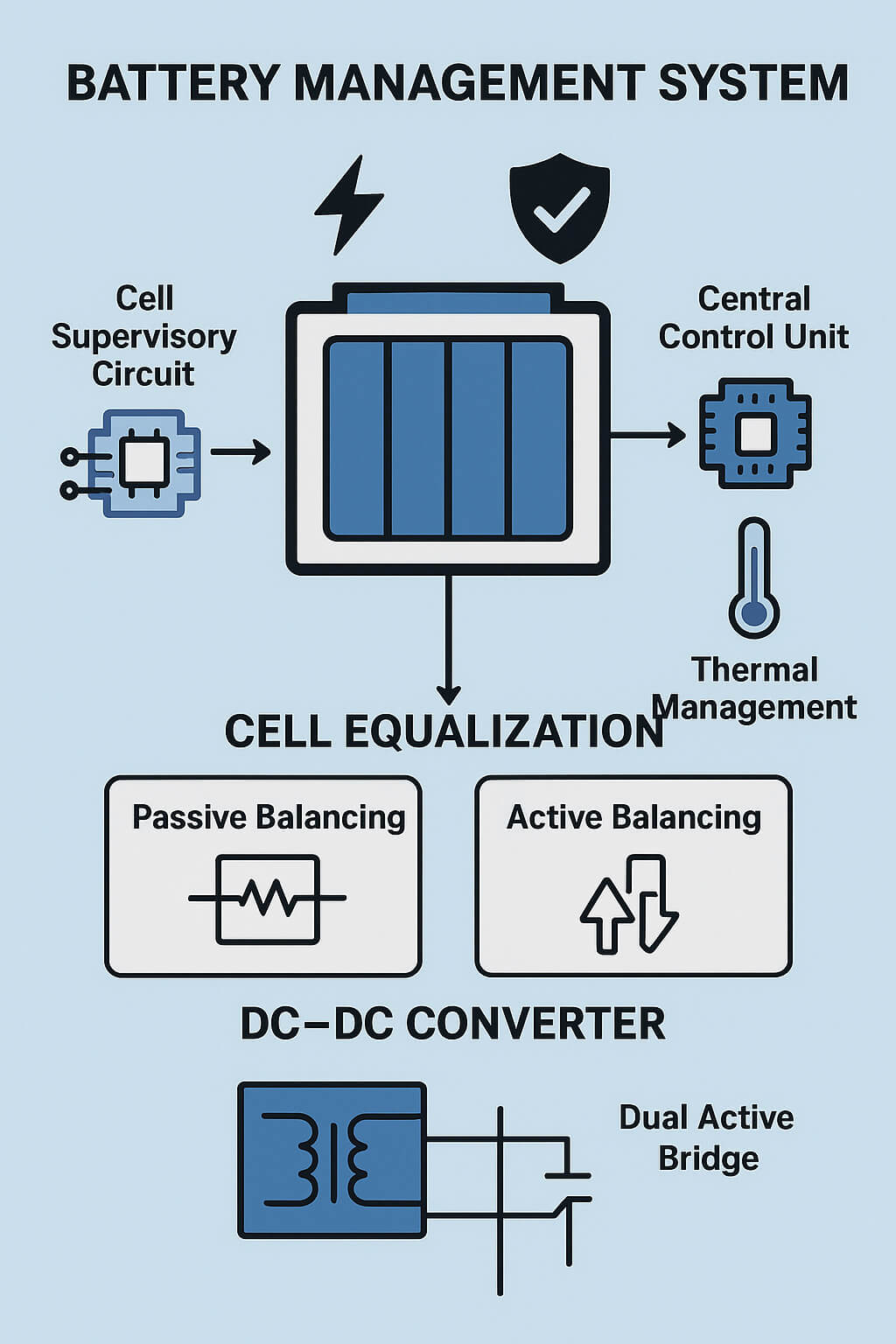
Battery Management Systems (BMS) are critical for ensuring the safety, reliability, and optimal performance of modern battery packs. Among the various BMS functions, cell balancing plays a pivotal role in mitigating capacity degradation and safety risks caused by cell imbalances originating from manufacturing variations and non-uniform operating conditions. This paper presents a comprehensive review of cell balancing strategies within BMS architectures. Passive and active cell balancing techniques are systematically classified and examined based on their operating principles, energy transfer mechanisms, and implementation requirements. In addition, DC-DC converter topologies employed in active cell balancing are reviewed, with particular emphasis on their structural features and control approaches. The analysis indicates that passive cell balancing methods offer simplicity and low cost but are limited by energy dissipation and reduced efficiency. Active cell balancing techniques demonstrate superior performance by enabling controlled energy redistribution among cells, thereby improving efficiency and voltage uniformity. Among the reviewed active approaches, converter based topologies especially the Dual Active Bridge (DAB) converter exhibit notable advantages in bidirectional power flow, high efficiency, and flexible control capability, albeit at the expense of increased system complexity. The reviewed findings highlight critical trade-offs among efficiency, complexity, and cost in the selection of cell balancing strategies for practical applications. Advanced active balancing techniques, supported by sophisticated converter topologies and control schemes, are identified as promising solutions for high capacity and dynamically operated battery systems. This review underscores the necessity for robust and adaptive BMS designs capable of meeting the evolving demands of real-world energy storage applications.Graphic Abstract
Keywords
The BMS is indispensable to maintaining the safety, reliability, and optimal performance of battery packs. The BMS functions are shown in Fig. 1. Failures in battery management can result in serious consequences, including premature battery degradation, thermal instability, and even catastrophic events such as fires or explosions. This paper initiates a comprehensive exploration of essential cell equalization methods for the BMS technology, highlighting their significance in advancing and refining battery systems. Despite promising outcomes in controlled testing environments, many existing techniques face limitations when applied in varied and dynamic real-world conditions, highlighting the urgent need for the development of more resilient and adaptive BMS solutions [1].

Figure 1: Functioning of battery management system. Adapted from Ref. [3]. Copyright@2016.
A typical BMS architecture comprises several vital components: battery modules with integrated Cell Supervisory Circuits (CSCs), a central control unit, high-side (HS) contactors, current sensors, and thermal management systems, all of which work collaboratively to ensure effective monitoring and control of battery operations. Calculating important metrics like the State of Charge (SoC) and State of Health (SoH) is essential to this functionality, which informs the vehicle’s operational readiness or State of Function (SoF).
However, lack of uniformity in cell manufacturing & varying load circumstances may result in imbalances among cells, negatively impacting battery life, SoC accuracy, internal resistance, thermal behavior, system efficiency, and overall safety. Precise cell monitoring and effective charge equalization are critical BMS functions that are necessary to prevent system failures and ensure long-term performance [2].
Cell imbalance within battery packs arises from a combination of internal and external factors that affect individual cell characteristics. Internally, variations introduced during manufacturing, such as discrepancies in capacity, internal resistance, and charge-discharge efficiency, can lead to unequal cell behavior. Externally, factors such as non-uniform current distribution in peripheral circuits and thermal inconsistencies across the battery pack further exacerbate the imbalance issues [4].
To address these challenges, cell equalization techniques are broadly categorized based on their energy management approaches: passive and active balancing [5]. Passive methods dissipate surplus energy from overcharged cells through resistive components. Although cost-effective and straightforward, these methods are inherently inefficient because of energy loss as heat. Active balancing, on the other hand, transfers energy from cells with larger charges to those with lower charges, employing sophisticated circuit topologies involving capacitors, inductors, transformers, or power electronic converters [6]. The classification of the cell equalization methods is illustrated in Fig. 2. This study provides a comprehensive review and comparative analysis of various active equalization techniques, highlighting their principles, advantages, and implementation challenges.

Figure 2: Cell equalization methods.
2 Cell Equalization Methods and Analysis
A. Passive Balancing
Shunt resistors are used in passive cell Equalizations redirect surplus charge from cells with higher voltage levels, dissipating this surplus energy as heat to equalize cell voltages. The dissipation rate is directly influenced by the voltage of the cells, with higher voltages resulting in greater energy loss during charging and discharging cycles [7]. This method is generally categorized into fixed and switch-controlled shunt resistor approaches and is most effective during the charging phase, as it lacks the bidirectional energy control required during discharge cycles [8]. Despite its simplicity and low implementation cost, passive balancing faces several critical limitations particularly in high-capacity battery systems used in Electric vehicles (EVs) and Hybrid Electric vehicles (HEVs) including restricted balancing current (typically 0.1–0.5 A), increased power loss, poor thermal efficiency, and inability to function effectively during discharging [8].
In contrast, active cell Equalization offers a more sophisticated and efficient approach by redistributing charges from higher-energy cells to lower-energy counterparts, rather than dissipating them. This dynamic energy transfer significantly improves system efficiency, prolongs battery life, and maintains better voltage consistency across cells, especially under frequent charge-discharge conditions [9]. These advantages do, however, come at the price of more complicated circuits and more expensive implementation. The comparison of passive and active balancers is given in Table 1. It provides distinct advantages, such as improved voltage uniformity, lower energy waste, enhanced overall system performance, and extended battery lifespan making it the go-to option for advanced BMS architectures in high-performance applications. A comparative analysis of various energy flow topologies is presented in Table 2.


2.1 Comparative Analysis of Active Cell Equalization Methods
Figs. 3 and 4 present the analysis of the cell equalization time and efficiency across various DC-DC converters. The radar charts reveal that the Bidirectional Flyback converter requires the shortest balancing time of approximately 1800 s whereas the dual active bridge converter provides nearly 98.5% efficiency.

Figure 3: Cell equalization time of all active cell balancers. Adapted from Ref. [13]. Copyright@2023.

Figure 4: Max. efficiency of DC-DC converter topologies for cell equalization. Adapted from Ref. [13]. Copyright@2023.
2.1.1 DC-DC Converter Topologies
The design and functionality of DC-DC converters are significantly influenced by the directionality of energy transfer. Unidirectional converters facilitate power flow solely from the source to the load, whereas Bidirectional converters are ideal for applications needing dynamic energy exchange, such as battery management systems, because they permit reversible energy transfer. Depending on whether a transformer is present in the circuit, DC-DC converters are further divided into isolated and non-isolated variants. High-frequency transformers are used in isolated converters to create galvanic separation between the input and output, increasing flexibility and safety [14].
Isolated topologies, particularly in active cell Equalization, offer notable advantages including compactness, cost-effectiveness, high balancing speeds, and improved energy efficiency, when compared to conventional capacitor- or transformer-based designs. This review underscores the necessity of optimizing both the conversion efficiency and cost-effectiveness for widespread commercial adoption [14].
To evaluate the energy-handling capabilities of the capacitive and inductive elements within these converter topologies, a quantitative comparison was performed by calculating the total accumulated energy stored in each component. This method provides a robust framework for assessing and optimizing component selection based on the energy demands of an application [15].
For capacitors:
For inductors (magnetic elements):
where,
In order to drastically lower switching losses, DC-DC converters also use soft-switching strategies like zero voltage switching (ZVS) and zero current switching (ZCS). These methods enhance power density and efficiency but introduce added complexity to control and circuit design. For instance, bidirectional Dual Active Bridge (DAB) converters implementing soft switching can achieve efficiencies approaching 95% under optimal conditions [17].
Compare the Factors of Various DC-DC Converters [18]:
Based on the reviewed articles, a qualitative comparison of various DC-DC converters is shown in Figs. 5 and 6.

Figure 5: Non-isolated DC-DC converter topologies. Adapted from Ref. [18]. Copyright@2023. Level: 1 = low, 2 = medium, 3 = high, and 4 = very high.

Figure 6: Isolated DC-DC converter topologies. Adapted from Ref. [18]. Copyright@2023. Level: 1 = low, 2 = medium, 3 = high, and 4 = very high.
Comparison of Various Topologies for DC-DC Converters and Control Techniques for BCE.
A. Buck-Boost Converter
The basic buck-boost converter topology is illustrated in Fig. 7. The converter regulates the output voltage to be either lower or higher than the input voltage. It operates in buck mode when the output is lower than the input, and in boost mode when the output exceeds the input voltage [19].

Figure 7: Buck-boost converter. Adapted from Ref. [19]. Copyright@2024.
The buck-boost converter can increase or decrease the supply voltage,
where,
L = Inductance
V = The average cell voltage
Ts = Switching period
∆IL = Inductance ripple current
D = Duty cycle.
It has fast balancing with high efficiency but it requires 2n − 2 switches and n − 1 inductors for n cells and also the voltage sensing and control technique is very complex [20].
B. Cuk Converter
The conventional Cuk equalizer topology, shown in Fig. 8, comprises n cells and n − 1 Cuk converter circuits, allowing neighboring cells to transfer energy exclusively. When cells requiring equalization are located far apart, energy must pass sequentially through the intermediate cells, leading to prolonged equalization times and reduced efficiency [21].

Figure 8: Cuk converter. Adapted from Ref. [21]. Copyright@2024.
Instead of using an inductor to transfer energy, the Cuk converter uses a capacitor.
Here, the duty ratio is denoted by D, the input voltage by Vin, the input inductance current ripple ∆Li, switching frequency by Fs, the output current by IDC, and the capacitor voltage ripple by ∆Vc. This configuration offers low ripple in both input and output currents, and capacitors that are more cost-effective than inductors for energy storage are preferred. However, the use of numerous components increases the overall volume of the system [22].
C. Resonant Converter
In order to facilitate energy transfer during the balancing process, two nearby battery cells are connected to a quasi-resonant converter. The switching devices are controlled by pulse width modulation (PWM) signals, which allow energy to be transferred between nearby cells [23].
Resonant converters, a class of DC-DC converters, employ a resonant tank circuit to enable soft switching either zero voltage switching (ZVS) or zero current switching (ZCS) which significantly reduces switching losses and improves efficiency. Compared with conventional converters, resonant converters offer several advantages, including reduced higher-order harmonic ripple content, smaller output filter requirements, and enhanced efficiency. However, they also present certain limitations, such as the introduction of non-linear behavior owing to the resonant tank circuit and the necessity of frequency modulation for control [24].
A bidirectional DC-DC converter with quasi-resonant zero-current switching (QRZCS) was suggested by a reviewer [25] as a component of a cell voltage balancing control strategy in Fig. 9. This reduces switching losses and enhances efficiency. Nevertheless, this approach faces several challenges, including complex circuit design, a high component count, reduced balancing time, and inefficiencies arising from MOSFETs that do not switch precisely at the zero-current point.

Figure 9: QRZCS battery equalizer from Ref. [26]. Copyright@2011.
Resonant converters use a tank circuit to reduce switching losses.
where
D. Push-Pull Converter
The push-pull converter configuration is shown in Fig. 10. This strategy has been found to be a promising one for lithium-ion battery packs’ active cell Equalization. However, its practical implementation presents several challenges, including issues related to scalability, increased design complexity, and the necessity for validation within real-time operating environments [28].

Figure 10: Cell equalization circuit using push-pull converter. From Ref. [28] Copyright@2021.
The push-pull topology acts as an isolated converter, separating the source and the load from galvanic contact. To guarantee optimum performance, the design procedure includes exact calculations of capacitance and inductance values,
where
E. Dual Active Bridge Converter (DAB)
In Fig. 11, the DAB converter is described. A bidirectional DC-DC topology is widely employed in battery balancing systems. It comprises two H-bridge circuits interconnected through a high-leakage inductance transformer, which enables galvanic isolation and efficient power transfer. Each H-bridge operates with a fixed 50% duty cycle and the energy transfer is controlled via phase shifting between the transformer’s primary and secondary sides. It can be controlled by two methods: the PWM method and the phase shift method [30]. Both the boost (cell-to-pack) and buck (pack-to-cell) operating modes are supported by the DAB converter, making it highly versatile for bidirectional energy flow in advanced battery management applications [31].

Figure 11: DAB converter-based battery balancing topology.
It offers galvanic isolation and excellent power transfer capabilities.
where D is the duty ratio,
Control Methods of Dual active bridge converter [33]
Single phase shift (SPS) modulation incorporates a single degree of freedom (D0), whereas both Dual phase shift (DPS) and Extended phase shift (EPS) extend this by utilizing two degrees of freedom (D0 and D1). By contrast, TPS uniquely introduces a third level of control, employing three degrees of freedom (D0, D1, and D2) [34].
a. Single phase shift control (SPS):
In the SPS modulation technique, the gate pulses of the waveforms are maintained as square waves, as shown in Fig. 12. A deliberate phase shift is introduced between these waveforms, which effectively governs the direction and magnitude of power transfer through H-bridge converters [35].

Figure 12: Gate pulses of SPS mode. From Ref. [26]. Copyright@2017.
As shown in Fig. 12, S1 and S3, Q5 and Q7 are 180° phase shifted. The Power flow equation under SPS control is,
where,
Vp = the output rms voltage of the primary bridge (H1)
Vs = the output rms voltage of secondary voltage (H2)
L= leakage inductance of primary plus secondary leakage inductance referred to primary side
fsw = switching frequency
δ = phase shift.
As illustrated in the above Fig. 13, the primary voltage Vpri leads the secondary voltage Vsec (exhibiting a positive phase shift ϕ), indicating that the DAB’s primary side is receiving power from the secondary side [35].

Figure 13: Voltage waveforms in SPS mode. From Ref. [26]. Copyright@2017.
b. Dual phase shift control (DPS):
The phase difference between S1 and S3 corresponds to D1. Similarly, the phase shift D0 is applied between S1 and Q5, as shown in Fig. 14, while S1 and S7 exhibit a lag of D0 + D1 rad. By adding an equal phase mismatch between the legs of each H-bridge (D1), Vpri and Vsec will be generated with three voltage levels (+Vdcx, 0, and −Vdcx), which contributes to increasing the efficiency of the HF transformer and lowering the THD.

Figure 14: Gate pulses of DPS mode. From Ref. [35]. Copyright@2017.
Power flow equation under DPS control [35],
Vp = the output rms voltage of the primary bridge (H1)
Vs = the output rms voltage of secondary voltage (H2)
L = Leakage inductance of primary plus secondary leakage inductance referred to primary side
fsw = switching frequency
Fig. 15 illustrates the Ipri and Isec waveforms resulting from the application of the DPS modulation to the DAB converter. In the DPS control although the peak values of Ipri and Isec are approximately twice as high, the reactive power and stress on the semiconductors are significantly reduced.

Figure 15: Primary and secondary waveforms in DPS mode. From Ref. [35]. Copyright@2017.
c. Extended Phase Shift (EPS) control:
Under EPS control, switching occurs between the diagonal switches of each bridge (e.g., S1 and S4 or Q1 and Q4), referred to as the inner phase shift (δin). Additionally, a separate phase shift, known as the outer phase shift (δout), is introduced between the two bridges, corresponding to Vp and Vs [36].
In Fig. 16 shows that the phase shift D1 is applied between S1 and S3 and S5 is D0 radian ahead of S1 but S7 is phase shifted by D0 + 180° from S1. Therefore, S5 and S7 were both out of phase.

Figure 16: Gate pulses of EPS mode. From Ref. [36]. Copyright@2017.
Power flow equation under EPS control [36],
Vp = output RMS voltage of the primary bridge (H1)
Vs = output RMS voltage of secondary voltage (H2)
L = Inductance
fsw = Switching frequency
δin = Inner phase shift
From Figs. 13 and 17, It can be concluded that the harmonic content in a Dual Active Bridge (DAB) operating under single phase shift (SPS) control (15.06% THD) is higher than that under extended phase shift (EPS) control (12.90% THD) [36].

Figure 17: Primary and secondary voltage & current waveforms in EPS mode. From Ref. [36]. Copyright@2024.
Despite its advantages, the DAB converter presents several practical control challenges [37] are,
• Dead-Time Effect: Excessive dead time can lead to voltage overshoots and associated switching losses.
• Phase Drift: Discrepancies between theoretical and actual phase shift may arise owing to parasitic voltage drops across power devices, component tolerances, and switching delays during Zero Voltage Switching (ZVS) transitions. High inductor current levels can reduce the duration of ZVS transitions, exacerbating this issue.
• DC Magnetic Flux Bias: In steady state, a DC bias may develop owing to mismatched circuit parameters such as gate-drive inconsistencies, varying turn-on/off delays, or unequal on-state resistances among switching devices. This bias can be mitigated by introducing DC-blocking capacitors in series with transformer windings. Transient DC bias may also occur because of temporary volt-second imbalances during phase shift updates, which can be controlled by limiting the peak inductor current.
F. Flyback Converter
As shown in Fig. 18 the bi-directional flyback converter supports bidirectional operation, functioning in both forward and reverse modes transferring energy from individual cells to the battery pack in the forward mode, and from the pack to individual cells in reverse mode [22]. The design outlined in the reviewed literature enables autonomous charge equalization without relying on dedicated cell voltage-sensing modules, thereby simplifying the system architecture and lowering the overall cost. The reported efficiencies for the charging and discharging processes are approximately 80.5% and 82.7%, respectively [38].

Figure 18: Bi-directional flyback schematic of the equalizer circuit among n cells. From Ref. [38]. Copyright@2015.
The flyback converter is an isolated version of the buck-boost converter.
where D is the duty ratio, V0 is the output voltage, FS is the resonance frequency, and ∆V0 is the output voltage ripple and R is load resistance. Compared with to the Dual Active Bridge (DAB) topology, this configuration utilizes fewer components and supports both cell-pack (CTP) and pack-cell (PTC) energy transfer modes. Although the overall design complexity is reduced, the inclusion of an isolation transformer leads to an increase in circuit size and contributes to higher implementation costs [38] which a shown in Fig. 19 and Tables 3 and 4.

Figure 19: Analysis of cell equalization adapted from Ref. [18]. Copyright@2023.


2.2 Critical Analysis and Research Implications
Current literature often treats converter topologies as modular performance units, focusing primarily on metrics such as efficiency, balancing time, and component count. However, this isolated approach neglects broader system-level impacts derived from the fundamental physics of energy transfer, control variances, and battery electrochemical behaviour.
A. Limitations of Efficiency-Focused Evaluation
While topologies like the Dual Active Bridge (DAB) report peak efficiencies exceeding 95% under steady-state conditions, these figures may be misleading in practical applications. Real-world equalization occurs during transient, partial-load, and asymmetric voltage states where parasitic effects become dominant. Under small voltage mismatches, the DAB converter experiences high reactive current, which reduces effective efficiency and increases semiconductor stress. Consequently, the energy overhead per unit of transferred charge serves as a more accurate metric than peak efficiency.
In scenarios with light loads or small voltage mismatches—common during the final stages of balancing the DAB converter experiences disproportionately high reactive current, which reduces effective efficiency and increases stress on semiconductors. Therefore, the energy overhead per unit of transferred charge, rather than peak efficiency, becomes a more relevant metric. This insight challenges the notion that higher-rated converters are always better for cell balancing tasks.
B. Control Complexity as an Underlying Performance Limitation
Advanced balancing systems typically assume ideal sensing and precise timing. In practice, aging and thermal fluctuations lead to errors in State-of-Charge (SoC) estimation, which can cause incorrect energy redistribution and exacerbate imbalances. Furthermore, sophisticated modulation techniques like Dual Phase Shift (DPS) and Extended Phase Shift (EPS) create complex control spaces. Factors such as parameter drift, digital delays, and dead-time effects can destabilize the control loop. Thus, control robustness—rather than switching strategy alone—is the primary determinant of system performance.
C. Scalability and Interconnection Trade-offs
Scalability is often highlighted as a significant benefit of active balancing, yet it presents considerable architectural challenges. Cell-to-cell (CTC) topologies scale linearly in terms of component count, leading to more failure points and increased wiring complexity in large battery packs. Cell-to-pack-to-cell (CTPTC) architectures reduce interconnections but concentrate power flow through shared magnetic components, creating thermal bottlenecks and single-point failure risks.
The input variable directly influences the accuracy and speed of the balancing process [49]. The various control strategies are shown in Fig. 20.

Figure 20: Classification of control strategies by control variables. Adapted from rom Ref. [18].
a. Voltage-Based Control: This is the most straightforward implementation, utilizing terminal voltage differences to trigger balancing. However, it is prone to inaccuracies due to internal resistance and the flat OCV curves characteristic of chemistries like LiFePO4. Errors in internal resistance measurement, often caused by battery aging, can lead to decreased capacity utilization [50]. This is known as Voltage Drop or Polarization, calculated as,
b. State-of-Charge (SoC)-Based Control: SoC-based control is considered the most effective indicator for balancing, as it manages energy based on the actual chemical state of the cell. This approach can reduce equalization time by up to 50% compared to voltage-based methods [51].
The methods for estimating SoC in batteries could be categorized into traditional, filter-based, observer-based, and data-driven approaches. Conventional methods include Look-up Table Methods [52] and Open Circuit Voltage (OCV). Filter-based methods [53] encompass the Extended Kalman Filter (EKF), Unscented Kalman Filter (UKF), and Cubature Kalman Filter (CKF). Observer-based methods [54] feature the Luenberger Observer (LO), Sliding Mode Observer (SMO), and H-infinity Observer (HIO). Data-driven methods include Artificial Neural Networks (ANN), SVM, Fuzzy Logic (FL), and Deep Learning (DL) [55].
While simple, look-up tables and ampere-hour integration struggle with accuracy and sensor drift in practical settings. In contrast, filtering and observation methods improve estimation reliability and noise rejection [56], though they require labour-intensive battery parameterization [57]. Machine learning offers a third path, identifying battery states without detailed physical models [58]. However, these data-driven strategies are prone to fitting errors based on training data quality and present significant computational challenges for on board deployment.
While machine learning and adaptive filters (EKF, UKF) offer improved reliability, their computational intensity often limits them to controlled environments. Consequently, direct measurement and bookkeeping remain the dominant methods in the commercial EV market.
As shown in Tables 5 and 6, the comparison of SOC estimation techniques reveals that most current methods suffer from drawbacks such as programming complexity, high memory demand, or susceptibility to sensor errors. While academic research continues to seek more robust solutions, these advanced algorithms are often difficult to implement outside of controlled environments. For this reason, conventional direct measurement and bookkeeping methods continue to dominate the commercial EV market [59,60].


This review confirms that the BMS is vital for the safety and efficiency of high-capacity battery packs in electric vehicles. While passive balancing is economically viable for low-power applications, active equalization, specifically via DAB converters, provides the efficiency and bidirectional capability required for modern energy storage. Future research must prioritize the integration of wide bandgap semiconductors (SiC and GaN) and AI-assisted control strategies to enhance dynamic performance and reliability under diverse operating conditions. Ultimately, the transition toward scalable and adaptive BMS architectures remains essential for meeting the demands of the evolving EV landscape.
Acknowledgement: The author would like to express sincere gratitude to Dr. Jalpa Thakkar, Supervisor, for her valuable guidance, insightful suggestions, and continuous support throughout the course of this research work. The author is also thankful to Prof. Shrikant J. Wagh, Provost, for his constant motivation and for providing the necessary resources and an encouraging research environment. We acknowledge all the researchers and authors whose published works have been referenced in this review, as their contributions have provided in-depth knowledge and a strong foundation for understanding the research area.
Funding Statement: The authors received no specific funding for this study.
Author Contributions: Conceptualization, literature survey, analysis, and manuscript preparation were performed by Jigneshkumar Joshi. Jalpa Thakkar contributed to supervision, critical review, and refinement of the manuscript. All authors reviewed and approved the final version of the manuscript.
Availability of Data and Materials: The findings of this study are available within the article and its supplementary materials. As this is a comprehensive review paper, all technical data, converter parameters, and performance metrics analyzed were derived from the published literature cited in the References section.
Ethics Approval: Not applicable.
Conflicts of Interest: The authors declare no conflicts of interest.
References
1. Liu K, Li K, Peng Q, Zhang C. A brief review on key technologies in the battery management system of electric vehicles. Front Mech Eng. 2019;14(1):47–64. doi:10.1007/s11465-018-0516-8. [Google Scholar] [CrossRef]
2. Dorn R, Schwartz R, Steurich B. Battery management system. In: Lithium-ion batteries: basics and applications. Berlin/Heidelberg, Germany: Springer; 2018. p. 165–75. doi:10.1007/978-3-662-53071-9_14. [Google Scholar] [CrossRef]
3. Hoque MM, Hannan MA, Mohamed A, Ayob A. Battery charge equalization controller in electric vehicle applications: a review. Renew Sustain Energy Rev. 2017;75(8):1363–85. doi:10.1016/j.rser.2016.11.126. [Google Scholar] [CrossRef]
4. Elvira DG, Valderrama Blavi H, Bosque Moncusi JM, Cid Pastor A, Garriga Castillo JA, Martinez Salamero L. Active battery balancing via a switched DC/DC converter: description and performance analysis. In: Proceedings of the 2019 16th Conference on Electrical Machines, Drives and Power Systems (ELMA); 2019 Jun 6–8; Varna, Bulgaria. p. 1–6. doi:10.1109/elma.2019.8771697. [Google Scholar] [CrossRef]
5. Khan N, Ooi CA, Alturki A, Amir M, Shreasth, Alharbi T. A critical review of battery cell balancing techniques, optimal design, converter topologies, and performance evaluation for optimizing storage system in electric vehicles. Energy Rep. 2024;11(1):4999–5032. doi:10.1016/j.egyr.2024.04.041. [Google Scholar] [CrossRef]
6. Daowd M, Omar N, Van Den Bossche P, Van Mierlo J. Passive and active battery balancing comparison based on MATLAB simulation. In: Proceedings of the 2011 IEEE Vehicle Power and Propulsion Conference; 2011 Sep 6–9; Chicago, IL, USA. p. 1–7. doi:10.1109/vppc.2011.6043010. [Google Scholar] [CrossRef]
7. Sugumar H. Overview of cell balancing methods for Li-ion battery technology. Energy Storage. 2020;3(2). doi:10.1002/est2.203. [Google Scholar] [CrossRef]
8. Lee WC, Drury D, Mellor P. Comparison of passive cell balancing and active cell balancing for automotive batteries. In: Proceedings of the 2011 IEEE Vehicle Power and Propulsion Conference; 2011 Sep 6–9; Chicago, IL, USA. doi:10.1109/vppc.2011.6043108. [Google Scholar] [CrossRef]
9. Babu PS, Ilango K. Comparative analysis of passive and active cell balancing of li-ion batteries. In: Proceedings of the 2022 Third International Conference on Intelligent Computing Instrumentation and Control Technologies (ICICICT); 2022 Aug 11–12; Kannur, India. doi:10.1109/icicict54557.2022.9917778. [Google Scholar] [CrossRef]
10. Lee Y, Jeon S, Bae S. Comparison on cell balancing methods for energy storage applications. Indian J Sci Technol. 2016;9(17):1–7. doi:10.17485/ijst/2016/v9i17/92316. [Google Scholar] [CrossRef]
11. Vitols K. Redesign of passive balancing battery management system to active balancing with integrated charger converter. In: Proceedings of the 2014 14th Biennial Baltic Electronic Conference (BEC); 2014 Oct 6–8; Tallinn, Estonia. [Google Scholar]
12. Pannickottu Nivya K, Deepa K. Active cell balancing for a 2s Lithium ion battery pack using flyback converter and push-pull converter. IOP Conf Ser Mater Sci Eng. 2021;1070(1):012097. doi:10.1088/1757-899x/1070/1/012097. [Google Scholar] [CrossRef]
13. Shylla D, Harikrishnan R, Swarnkar R. Comparative analysis and evaluation of the different active cell balancing topologies in lithium ions batteries. J Electrochem Soc. 2023;170(8):080501. doi:10.1149/1945-7111/ace958. [Google Scholar] [CrossRef]
14. Turksoy A, Teke A, Alkaya A. A comprehensive overview of the DC-DC converter-based battery charge balancing methods in electric vehicles. Renew Sustain Energy Rev. 2020;133(3):110274. doi:10.1016/j.rser.2020.110274. [Google Scholar] [CrossRef]
15. Gallardo-Lozano J, Romero-Cadaval E, Milanes-Montero MI, Guerrero-Martinez MA. Battery equalization active methods. J Power Sources. 2014;246:934–49. doi:10.1016/j.jpowsour.2013.08.026. [Google Scholar] [CrossRef]
16. Pourjafar S, Afshari H, Mohseni P, Husev O, Matiushkin O, Shabbir N. Comprehensive comparison of isolated high step-up DC-DC converters for low power application. IEEE Open J Power Electron. 2024;5(9):1149–61. doi:10.1109/ojpel.2024.3433554. [Google Scholar] [CrossRef]
17. Ravi D, Mallikarjuna Reddy B, Letha SS, Samuel P. Bidirectional DC to DC converters: an overview of various topologies, switching schemes and control techniques. Int J Eng Technol. 2018;7(4.5):360. doi:10.14419/ijet.v7i4.5.20107. [Google Scholar] [CrossRef]
18. Sugumaran G, Prabha NA. A comprehensive review of various topologies and control techniques for DC-DC converter-based lithium-ion battery charge equalization. Int Trans Electr Energy Syst. 2023;2023:3648488. doi:10.1155/2023/3648488. [Google Scholar] [CrossRef]
19. Sharma A, Adhikari A, Adhikari B, Pandey P, Tamrakar I. Active cell balancing approach for efficient battery management system. KEC J Sci Eng. 2024;8(1):23–6. doi:10.3126/kjse.v8i1.69260. [Google Scholar] [CrossRef]
20. Ding X, Zhang D, Cheng J, Wang B, Chai Y, Zhao Z, et al. A novel active equalization topology for series-connected lithium-ion battery packs. IEEE Trans Ind Appl. 2020;56(6):6892–903. doi:10.1109/tia.2020.3015820. [Google Scholar] [CrossRef]
21. Zhang Y, Tian S, Zhang Y. A new equalization method for lithium-ion battery packs based on Cuk converter. Energy Eng. 2024;121(6):1459–72. doi:10.32604/ee.2024.047247. [Google Scholar] [CrossRef]
22. Marimuthu G, Umamaheswari MG. Analysis and design of single stage bridgeless Cuk converter for current harmonics suppression using particle swarm optimization technique. Electr Power Compon Syst. 2019;47(11–12):1101–15. doi:10.1080/15325008.2019.1630692. [Google Scholar] [CrossRef]
23. Brahmbhatt A, Mankad P. Effective cell balancing methods for electric vehicle applications: a review. J Electr Syst. 2024;20:3081–91. [Google Scholar]
24. Mudiyanselage GA, Keshmiri N, Emadi A. A review of DC-DC resonant converter topologies and control techniques for electric vehicle applications. IEEE Open J Power Electron. 2023;4:945–64. doi:10.1109/ojpel.2023.3331180. [Google Scholar] [CrossRef]
25. Lee YS, Cheng GT. Quasi-resonant zero-current-switching bidirectional converter for battery equalization applications. IEEE Trans Power Electron. 2006;21(5):1213–24. doi:10.1109/tpel.2006.880349. [Google Scholar] [CrossRef]
26. Yu Y, Saasaa R, Khan AA, Eberle W. A series resonant energy storage cell voltage balancing circuit. IEEE J Emerg Sel Top Power Electron. 2020;8(3):3151–61. doi:10.1109/jestpe.2019.2914706. [Google Scholar] [CrossRef]
27. Farahani G. DC-DC series-resonant converter with multi stage current driven for balance charger of series connected lithium ion batteries. IET Power Electron. 2021;14(5):992–1007. doi:10.1049/pel2.12081. [Google Scholar] [CrossRef]
28. Jayasree KS, Vijaya Chandrakala KRM. Active cell balancing technique for improved charge equalization in lithium-ion battery stack. In: Proceedings of the 2021 4th International Conference on Recent Developments in Control, Automation & Power Engineering (RDCAPE); 2021 Oct 7–8; Noida, India. p. 160–4. doi:10.1109/rdcape52977.2021.9633385. [Google Scholar] [CrossRef]
29. Angulo-García D, Angulo F, Muñoz JG. DC-DC Zeta power converter: ramp compensation control design and stability analysis. Appl Sci. 2021;11(13):5946. doi:10.3390/app11135946. [Google Scholar] [CrossRef]
30. Tiwari VK, Asim M, Aftab Alam MD, Siddiqui MI, Alam MA. Implementation of single-phase shift (SPS) and extended phase shift (EPS) for dual active bridge (DAB). Indian J Sci Technol. 2024;17(41):4262–9. doi:10.17485/ijst/v17i41.2456. [Google Scholar] [CrossRef]
31. Bhattacharjee AK, Batarseh I. Optimum hybrid modulation for improvement of eDciency over wide operating range for triple-phase-shift dual-active-bridge converter. IEEE Trans Power Electron. 2020;35(5):4804–18. doi:10.1109/tpel.2019.2943392. [Google Scholar] [CrossRef]
32. Wang J, Qiao X, Li L, Li R. An optimal control for dual active bridge converter in battery charging applications. IET Power Electron. 2025;18(1):e12850. doi:10.1049/pel2.12850. [Google Scholar] [CrossRef]
33. Shao S, Chen L, Shan Z, Gao F, Chen H, Sha D, et al. Modeling and advanced control of dual-active-bridge DC-DC converters: a review. IEEE Trans Power Electron. 2022;37(2):1524–47. doi:10.1109/tpel.2021.3108157. [Google Scholar] [CrossRef]
34. Coelho S, Sousa TJC, Monteiro V, Machado L, Afonso JL, Couto C. Comparison and validation of five modulation strategies for a dual active bridge converter. EAI Endorsed Trans Energy Web. 2023;9(6):e2. doi:10.4108/ew.v9i6.3066. [Google Scholar] [CrossRef]
35. Kumar BM, Kumar A, Bhat AH, Agarwal P. Comparative study of dual active bridge isolated DC-to-DC converter with single-phase shift and dual phase shift control techniques. In: Proceedings of the 2017 Recent Developments in Control, Automation & Power Engineering (RDCAPE); 2017 Oct 26–27; Noida, India. p. 453–8. doi:10.1109/rdcape.2017.8358314. [Google Scholar] [CrossRef]
36. Hou N, Song W, Li Y, Zhu Y, Zhu Y. A comprehensive optimization control of dual-active-bridge DC-DC converters based on unified-phase-shift and power-balancing scheme. IEEE Trans Power Electron. 2019;34(1):826–39. doi:10.1109/tpel.2018.2813995. [Google Scholar] [CrossRef]
37. Zhang C, Li Y, Huang J, Xia Z, Liu J. Research on alternating equalization control systems for lithium-ion cells charging. World Electr Veh J. 2021;12(3):114. doi:10.3390/wevj12030114. [Google Scholar] [CrossRef]
38. Guo X, Geng J, Liu Z, Xu X, Cao W. A flyback converter-based hybrid balancing method for series-connected battery pack in electric vehicles. IEEE Trans Veh Technol. 2021;70(7):6626–35. doi:10.1109/tvt.2021.3087320. [Google Scholar] [CrossRef]
39. Kim M-Y, Jong WK, Kim CH, Cho SY, Moon GW, Jong WK. Automatic charge equalization circuit based on regulated voltage source for series connected lithium-ion batteries. In: Proceedings of the 8th International Conference on Power Electronics-ECCE Asia; 2011 May 30–Jun 3; Jeju, Republic of Korea. [Google Scholar]
40. Dam SK, John V. Low-frequency selection switch based cell-to-cell battery voltage equalizer with reduced switch count. IEEE Trans Ind Appl. 2021;57(4):3842–51. doi:10.1109/tia.2021.3075184. [Google Scholar] [CrossRef]
41. Zhong H, Li J, Wang Y-X. A bus-based battery equalization via modi9ed isolated CUK converter governed by adaptive control. In: Proceedings of the Chinese Automation Congress (CAC); 2019 Nov 22–24; Hangzhou, China. [Google Scholar]
42. Pham VL, Duong VT, Choi W. High-efficiency active cell-to-cell balancing circuit for Lithium-Ion battery modules using LLC resonant converter. J Power Electron. 2020;20(4):1037–46. doi:10.1007/s43236-020-00088-6. [Google Scholar] [CrossRef]
43. Lee IO. Hybrid PWM-resonant converter for electric vehicle on-board battery chargers. IEEE Trans Power Electron. 2016;31(5):3639–49. doi:10.1109/tpel.2015.2456635. [Google Scholar] [CrossRef]
44. Vulligaddala VB, Vernekar S, Singamla S, Adusumalli RK, Ele V, Brandl M, et al. A 7-cell, stackable, Li-ion monitoring and active/passive balancing IC with in-built cell balancing switches for electric and hybrid vehicles. IEEE Trans Ind Inf. 2020;16(5):3335–44. doi:10.1109/tii.2019.2953939. [Google Scholar] [CrossRef]
45. Pham VL, Duong VT, Choi W. A low cost and fast cell-to-cell balancing circuit for lithium-ion battery strings. Electronics. 2020;9(2):248. doi:10.3390/electronics9020248. [Google Scholar] [CrossRef]
46. Shang Y, Xia B, Zhang C, Cui N, Yang J, Mi C. A modularization method for battery equalizers using multiwinding transformers. IEEE Trans Veh Technol. 2017;66(10):8710–22. doi:10.1109/tvt.2017.2702065. [Google Scholar] [CrossRef]
47. Sun J, Zhu C, Lu R, Song K, Wei G. Development of an optimized algorithm for bidirectional equalization in lithium-ion batteries. J Power Electron. 2015;15(3):775–85. doi:10.6113/jpe.2015.15.3.775. [Google Scholar] [CrossRef]
48. Lim JW, Hassan J, Kim M. Bidirectional soft switching push–pull resonant converter over wide range of battery voltages. IEEE Trans Power Electron. 2021;36(11):12251–67. doi:10.1109/tpel.2021.3078413. [Google Scholar] [CrossRef]
49. Gabbar HA, Othman AM, Abdussami MR. Review of battery management systems (BMS) development and industrial standards. Technologies. 2021;9(2):28. doi:10.3390/technologies9020028. [Google Scholar] [CrossRef]
50. Feng F, Hu X, Liu J, Lin X, Liu B. A review of equalization strategies for series battery packs: variables, objectives, and algorithms. Renew Sustain Energy Rev. 2019;116(4):109464. doi:10.1016/j.rser.2019.109464. [Google Scholar] [CrossRef]
51. Wadi A, Abdel-Hafez M, Hussein A, Alkhawaja F. Alleviating dynamic model uncertainty effects for improved battery SOC estimation of EVs in highly dynamic environments. IEEE Trans Veh Technol. 2021;70(7):6554–66. doi:10.1109/tvt.2021.3085006. [Google Scholar] [CrossRef]
52. Klintberg A, Zou C, Fridholm B, Wik T. Kalman filter for adaptive learning of two-dimensional look-up tables applied to OCV-curves for aged battery cells. Control Eng Pract. 2019;84(1):230–7. doi:10.1016/j.conengprac.2018.11.023. [Google Scholar] [CrossRef]
53. Li W, Yang Y, Wang D, Yin S. The multi-innovation extended Kalman filter algorithm for battery SOC estimation. Ionics. 2020;26(12):6145–56. doi:10.1007/s11581-020-03716-0. [Google Scholar] [CrossRef]
54. Tang X, Liu B, Lv Z, Gao F. Observer based battery SOC estimation: using multi-gain-switching approach. Appl Energy. 2017;204:1275–83. doi:10.1016/j.apenergy.2017.03.079. [Google Scholar] [CrossRef]
55. Ren Z, Du C. A review of machine learning state-of-charge and state-of-health estimation algorithms for lithium-ion batteries. Energy Rep. 2023;9(12):2993–3021. doi:10.1016/j.egyr.2023.01.108. [Google Scholar] [CrossRef]
56. Shrivastava P, Soon TK, Bin Idris MYI, Mekhilef S. Overview of model-based online state-of-charge estimation using Kalman filter family for lithium-ion batteries. Renew Sustain Energy Rev. 2019;113(4):109233. doi:10.1016/j.rser.2019.06.040. [Google Scholar] [CrossRef]
57. Wu L, Pang H, Geng Y, Liu X, Liu J, Liu K. Low-complexity state of charge and anode potential prediction for lithium-ion batteries using a simplified electrochemical model-based observer under variable load condition. Int J Energy Res. 2022;46(9):11834–48. doi:10.1002/er.7949. [Google Scholar] [CrossRef]
58. Tian H, Qin P. State of health prediction for lithium-ion batteries with a novel online sequential extreme learning machine method. Int J Energy Res. 2021;45(2):2383–97. doi:10.1002/er.5934. [Google Scholar] [CrossRef]
59. Meng J, Ricco M, Luo G, Swierczynski M, Stroe DI, Stroe AI, et al. An overview and comparison of online implementable SOC estimation methods for lithium-ion battery. IEEE Trans Ind Appl. 2018;54(2):1583–91. doi:10.1109/tia.2017.2775179. [Google Scholar] [CrossRef]
60. Zhang M, Fan X. Review on the state of charge estimation methods for electric vehicle battery. World Electr Veh J. 2020;11(1):23. doi:10.3390/wevj11010023. [Google Scholar] [CrossRef]
61. Ouyang Q, Han W, Zou C, Xu G, Wang Z. Cell balancing control for lithium-ion battery packs: a hierarchical optimal approach. IEEE Trans Ind Inf. 2020;16(8):5065–75. doi:10.1109/tii.2019.2950818. [Google Scholar] [CrossRef]
62. Uzair M, Abbas G, Hosain S. Characteristics of battery management systems of electric vehicles with consideration of the active and passive cell balancing process. World Electr Veh J. 2021;12(3):120. doi:10.3390/wevj12030120. [Google Scholar] [CrossRef]
Cite This Article
 Copyright © 2026 The Author(s). Published by Tech Science Press.
This work is licensed under a Creative Commons Attribution 4.0 International License , which permits unrestricted use, distribution, and reproduction in any medium, provided the original work is properly cited.
 Downloads
 Citation Tools
