
 Submit a Paper
 Propose a Special lssue
 Open Access
ARTICLE

Prediction of Cuttings-Induced Annular-Pressure Loss in Extended-Reach Wells
1
Key Laboratory of Enhanced Oil Recovery in Fracture-Vug Reservoir, SINOPEC, Urumuqi, 830011, China
2
State Key Laboratory of Oil & Gas Reservoir Geology and Exploitation, Southwest Petroleum University, Chengdu, 610500, China
*
Corresponding Author: Gui Wang. Email: wanggui@swpu.edu.cn
Fluid Dynamics & Materials Processing 2023, 19(11), 2877-2890. https://doi.org/10.32604/fdmp.2023.029206
Received 07 February 2023; Accepted 05 May 2023; Issue published 18 September 2023
 View Full Text
 Download PDF
Abstract
Drill cuttings are broken bits of solid material removed from a borehole drilled by rotary, percussion, or auger methods and brought to the surface in the drilling mud. When these cuttings enter the annulus, they have an effect on the drilling fluid rheology and density, which is, in general, quite difficult to evaluate. By introducing an empirical correlation for the rheological properties of cuttings-laden drilling fluids, this study proposes a pressure-loss prediction method for an extended-reach well (ERW). After verifying the accuracy of this method, a case study is considered and a sensitivity analysis is conducted assuming a yield-power law fluid. The results show that an increased concentration of cuttings in the annulus contributes to an increased annular pressure loss. Compared to their effect on the drilling fluid density, cuttings have a greater impact on the drilling fluid rheology. A larger rate of penetration contributes to an increased annular pressure loss. For higher drilling fluid flow rates, the annular pressure loss first decreases and then it increases. In addition, the annular pressure loss becomes higher as the cuttings’ particle size decreases and the cuttings’ concentration grows.Keywords
Nomenclature
| a, b, c | Empirical coefficients for the flow behavior index, dimensionless |
| Cs | Cuttings concentration, % |
| D50 | Average particle size, mm |
| Di | Inner diameter of annulus, mm |
| Do | Outer diameter of annulus, mm |
| fi | Friction factor for each part, dimensionless |
| FT | Cuttings transport ratio, dimensionless |
| K0 | Consistency coefficient of basic drilling fluid, Pa·sn |
| K | Consistency coefficient, Pa·sn |
| m, p, q | Empirical coefficients for the consistency coefficient, dimensionless |
| n0 | Flow behavior index of basic drilling fluid, dimensionless |
| n | Flow behavior index, dimensionless |
| qm | Drilling fluid flow rate, m3/s |
| va | Drilling fluid velocity, m/s |
| Re | Reynolds number, dimensionless |
| Greek | |
| γ | Shear rate, s−1 |
| ρm | Drilling fluid density, g/cm3 |
| ρs | Cuttings density, g/cm3 |
| τ0 | Yield stress, Pa |
| τ | Shear stress, Pa |
| Δpa | Total annular pressure loss, MPa |
| | Pressure loss in deviated sections, MPa |
| Δph | Pressure loss in horizontal section, MPa |
| Δpv | Pressure loss in vertical section, MPa |
Extended-reach wells (ERWs) have been widely used in thin productive reservoirs, fractured reservoirs, and low permeability reservoirs. During ERW drilling, the prediction of annular pressure loss is one of the biggest concerns [1]. An inaccurate annular pressure loss may lead to some dangerous drilling consequences such as loss of circulation, wellbore instability, stuck pipe, etc. [2–5].
The reliable prediction of annular pressure loss is dependent on the density and rheology of drilling fluids. On the one hand, after drilling cuttings enter the annulus, the effective density of the annulus drilling fluid will inevitably be affected, thus affecting the bottomhole pressure. On the other hand, drilling fluid rheology is directly related to the calculation of the friction coefficient in the prediction of annular pressure loss. To obtain a reliable pressure loss prediction, therefore, it is important to accurately determine the rheological parameters of cuttings-laden drilling fluids.
Numerous studies on the rheological behavior of drilling fluids have been conducted considering the factors involved such as temperature, pressure, polymer, etc. [4–8]. However, the effect of cuttings on drilling fluid rheology has received little concern, let alone considerations of the cuttings’ effect on annular pressure loss. It is commonly assumed that there are no cuttings’ effects on the rheological properties of the drilling fluid when calculating the annular pressure loss. In fact, in drilling operations, as shown in Fig. 1 a large amount of drill cuttings enters the wellbore annulus. It is known that cuttings increase the drilling fluid density and result in a higher annular pressure loss, which can reduce the horizontal extended-reach limit [9].
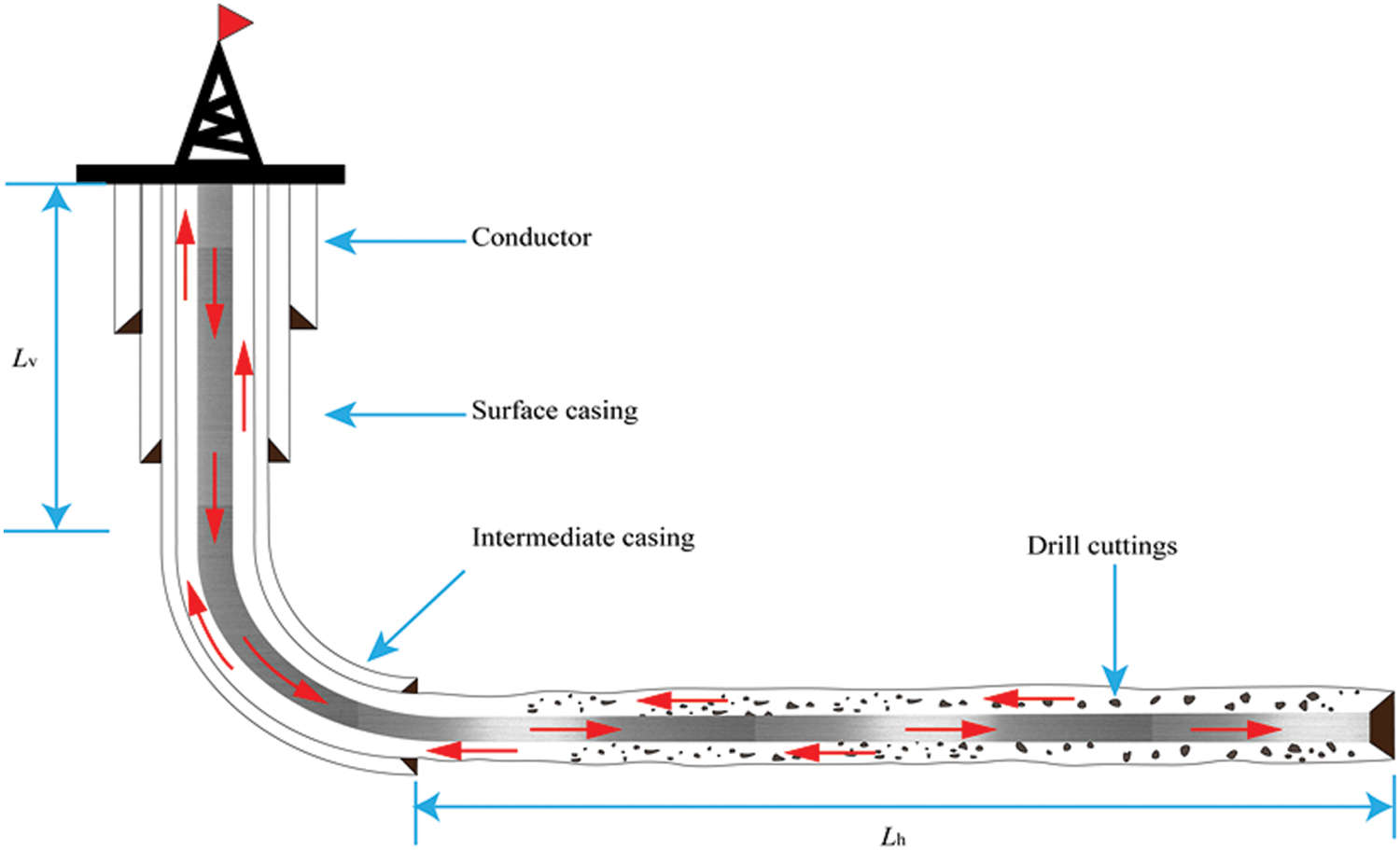
Figure 1: Schematic of an extended-reach well with cuttings in an annulus
The aim of this study is to couple the cuttings’ effects on the rheology and density of drilling fluids into the pressure loss calculation. To evaluate the extent and regularity of the cuttings’ effect on the pressure loss, a case study was conducted. The sensitivity analyses of rate of penetration (ROP), drilling fluid flow rate, and cuttings particle size effects on the annular pressure loss were carried out.
2.1 Rheological Model of Cuttings-Laden Drilling Fluid
For a long time, the rheology of cuttings-laden drilling fluid could hardly be measured. As shown in Fig. 2, due to a too small measuring gap of the rotational viscometer, the solid cuttings cannot enter or would be stuck in the gap. Previous research shows that with the increased amount of cuttings and decreased particle size, the consistency coefficient increases, while the flow behavior index decreases [10].
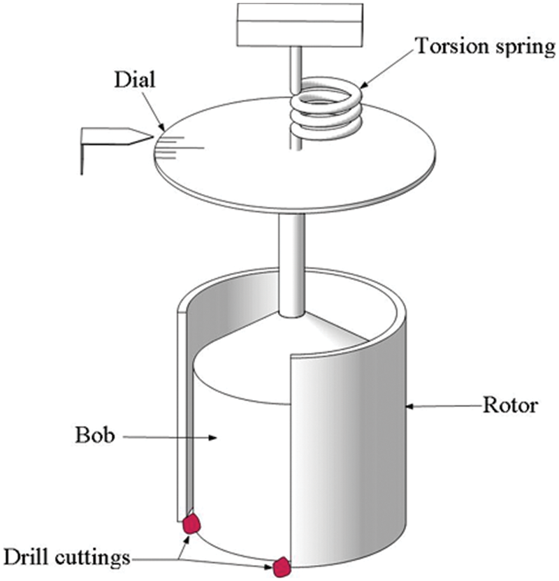
Figure 2: Schematic of a rotational viscometer with cuttings
To describe the rheological performance of drilling fluids, the Herschel-Bulkley model was used in this study. By introducing cuttings effects on rheology into the expression for the Herschel-Bulkley model, a modified version can be expressed as [11]
where n0 is the flow behavior index of the base drilling fluid (without cuttings), dimensionless; K0 is the consistency coefficients of the base drilling fluid (without cuttings), Pa·sn; Cs is the cuttings concentration, %; D50 is the median size of cuttings, mm; a, b, c, m, p and q are empirical coefficients.
2.2 Calculation of Cuttings Concentration
Cuttings concentration directly affects the density and rheology of the drilling fluid. Nevertheless, the calculation procedure for the cuttings concentration is complicated due to the iterative calculation involved. Fig. 3 summarizes the process for determining the cuttings concentration.
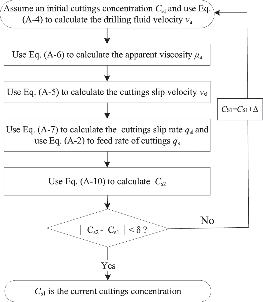
Figure 3: Computational flowchart of cuttings concentration
The volume fraction of drill cuttings in the annulus is defined as [12]
where qs is the feed rate of cuttings, m3/s; qm is the drilling fluid flow rate, m3/s; and FT is the cuttings transport ratio, dimensionless. Please refer to Appendix A for the details of the cuttings concentration calculation.
In the process of drilling, as the cuttings enter the annulus, the material in the wellbore becomes a mixture of drilling fluids and cuttings [12]. The effective density of the mixture can be determined by
where ρe represents the effective density of the mixture, g/cm3; ρm represents the fluid density, g/cm3; ρs represents the solid cuttings density, g/cm3.
2.3 Prediction of Annular Pressure Loss
A horizontal ERW can be mainly divided into vertical section, deviated sections, and horizontal section. Accordingly, frictional pressure loss Δpa in an annulus can be calculated by
where Δpv is the pressure loss in the vertical section, MPa; Δpdi is the annular pressure loss in the deviated section, MPa; Δph is the annular pressure loss in the horizontal section, MPa. Please refer to Appendix B for the details of the pressure loss of each section. The calculation process of annular pressure is shown in Fig. 4.
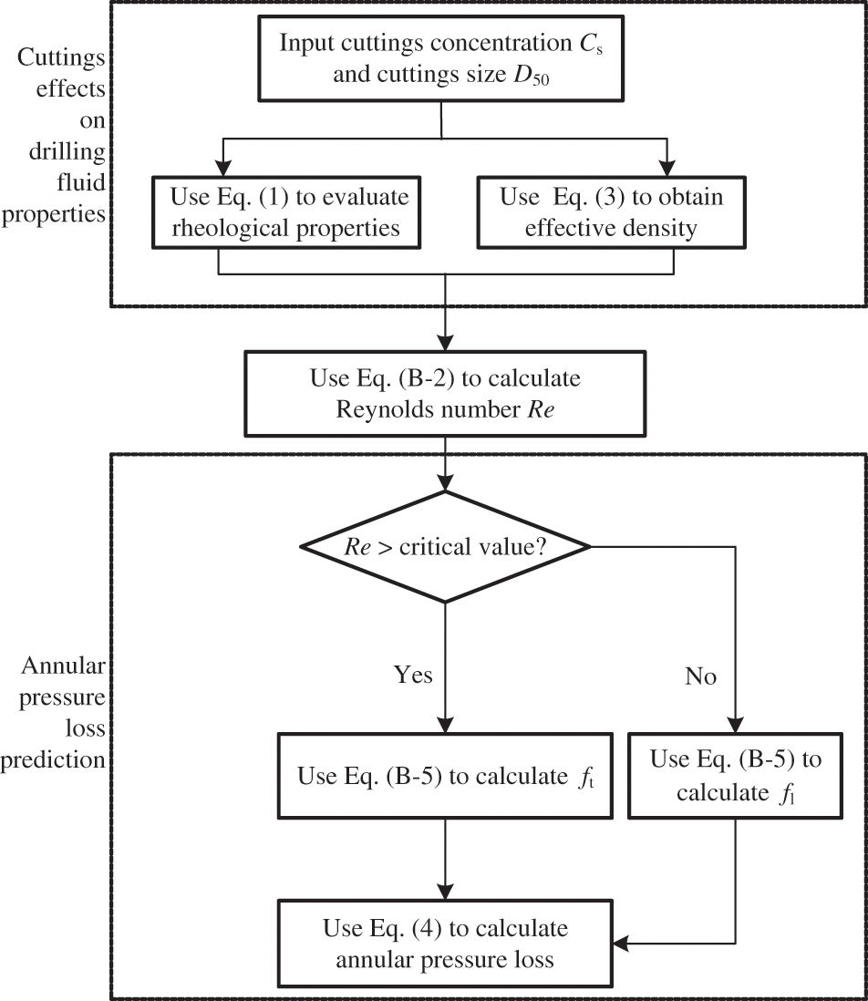
Figure 4: Flowchart of annular pressure loss computation
Considering the cuttings effects, a horizontal ERW was selected to analyze the effects of different parameters on the annular pressure loss [11]. The input data for the parameter sensitivity analysis is presented in Appendix C.
The effectiveness of the proposed method is verified by the experimental results in the literature [13]. The experiment was carried out in a flow loop with non-Newtonian fluids. With cuttings injection, the test facility can test the friction annular pressure loss for cuttings-laden drilling fluids. For comparison, the same parameters including consistency coefficient, flow behavior, pipe diameters, and drilling fluid density were used in the proposed method. Fig. 5 shows the pressure loss vs. average fluid velocity for a given drilling fluid.
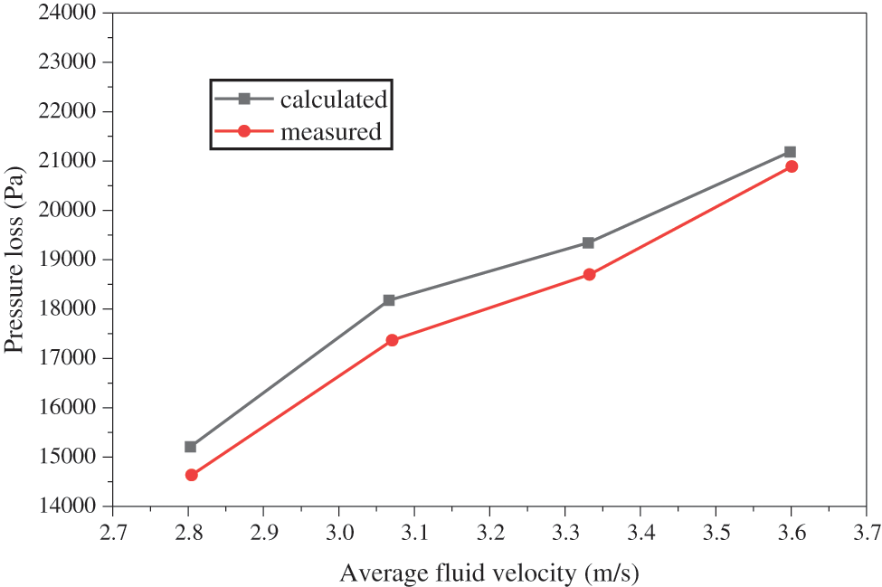
Figure 5: Comparison between the experimental results and the proposed method
The presented method with cuttings effects follows well the experimental results of Sorgun et al. [14,15]. It is evident that the presented model has a high degree of accuracy to predict the pressure loss.
3.2 Effect of Rate of Penetration
The rate of penetration (ROP) is defined as the speed at which the drill bit breaks the rock. The ROP has an inevitable effect on the concentration of cuttings. Under the same conditions, the cuttings concentration increases with the increase of the ROP, which has a great impact on the drilling fluid density and rheology. Therefore, the ROP has a great impact on the annular pressure loss.
For comparison, the annular pressure loss was also calculated for the case that only considered the effect of drill cuttings on the drilling fluid density. The results for annular pressure loss vs. ROP are presented in Fig. 6.

Figure 6: Effects of ROP on annular pressure loss with the effect of cuttings
When only considering the cuttings effects on annulus fluid density, the variation of annular pressure loss is not noticeable. This trend clearly indicates that there is little change in annular pressure loss if only the cuttings effect on drilling fluid density is considered. On the contrary, a significant growth trend can be seen with the cuttings effects on both the density and rheology of the drilling fluid. This can be explained by the fact that a higher ROP results in a higher production of cuttings in an annulus [16]. As a result, the effect on rheology leads to an increase in the annular pressure loss as ROP increases. Considering the effect of cuttings on both the density and rheology of the drilling fluid, Fig. 7 shows the variation in annular pressure loss as the ROP grows for varying flow rates.
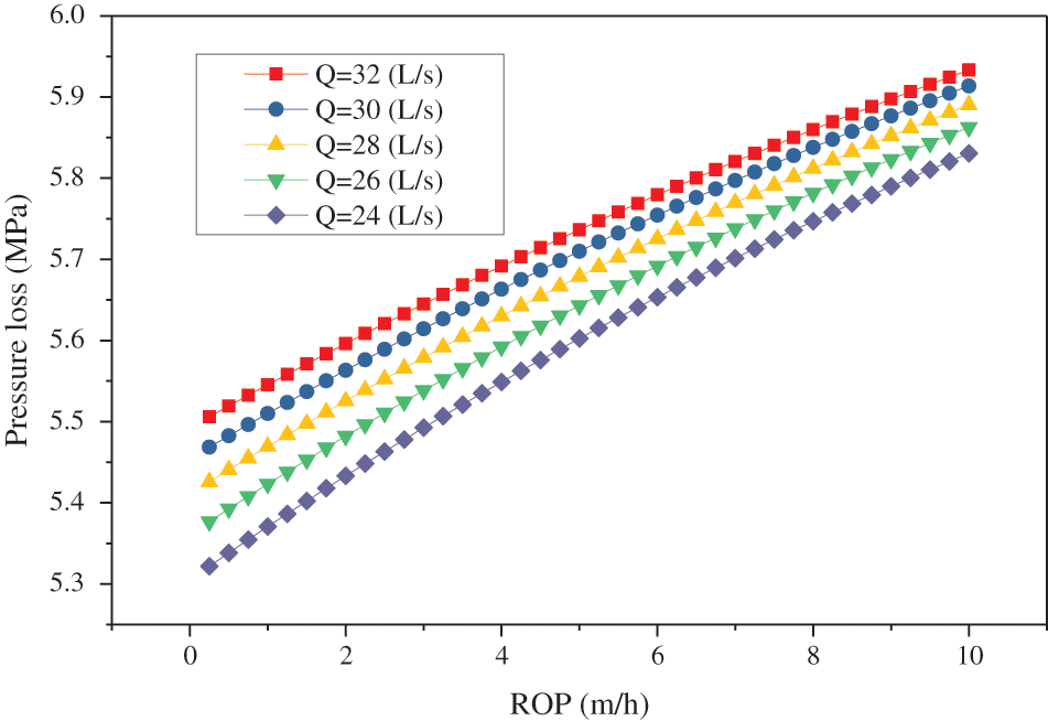
Figure 7: Effects of ROP on annular pressure loss for varying flow rates
The higher the ROP at a given flow rate, the greater the annular pressure loss. The reason for this trend is that the cuttings concentration in the annulus increases with the increase of ROP, which leads to an increase in the density of the drilling fluid and an increase in viscosity, resulting in an increase in the annular pressure loss.
In principle, on the one hand, the increase in flow rate leads to an increase in flow resistance, resulting in a larger pressure loss [17]; on the other hand, the larger the flow rate, the smaller the cuttings concentration, resulting in a reduction in the annular pressure loss.
To illustrate the importance of considering the cuttings effect on the drilling fluid properties, Fig. 8 depicts the comparison of the pressure loss calculated with and without the cuttings effect.
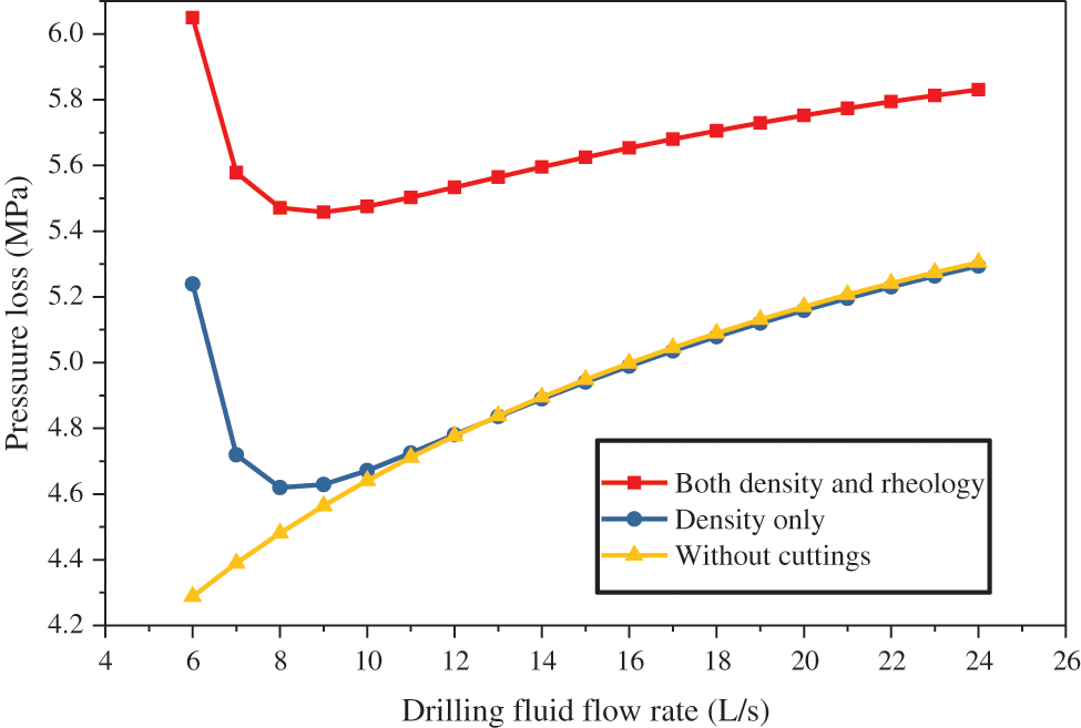
Figure 8: Comparison of pressure loss with and without cuttings effects
If there are no cuttings in the annulus, the pressure loss increases with the increased flow rate. For comparison, when considering the effect of cuttings on drilling fluids, there are two cases for annular pressure loss. The two cases about the pressure loss curves both show a similar trend of decreasing first and then increasing, and the value of the annular pressure loss for each curve is minimized at a certain flow rate (8 L/s in this study). This can be explained by the fact that in the low range of flow rate, the drilling fluid has a weak carrying capacity for cuttings, resulting in a high cuttings concentration and therefore a high annular pressure loss. While, in the high range of flow rate, the increase in pressure loss mainly results from the increase in flow resistance. Furthermore, the annular pressure loss is greater in the case of considering the cuttings effects on the drilling fluid rheology. The variation of annular pressure loss with the drilling fluid flow rate at varying ROPs is shown in Fig. 9.

Figure 9: Effects of flow rate on annular pressure loss for varying ROPs
The effect of flow rate on pressure loss is related to the ROP. When the ROP is equal to 0, the pressure loss increases with the flow rate. Before the ROP reaches a certain value (6 m/h in this study), the pressure loss increases with the increased drilling fluid flow rate. When the ROP exceeds the certain value, the annular pressure loss first decreases and then increases with the flow rate. This phenomenon can be explained by the reasoning that less cuttings generated at low ROP can be easily carried out of the wellbore, but when cuttings are increasingly generated at high ROP, transportation of the cuttings becomes more difficult and the annular cuttings concentration increases significantly.
Cuttings size influences the rheological properties of the drilling fluid, which affects the annular pressure loss. Small-sized cuttings have a greater impact on drilling fluid rheology than large-sized cuttings [18]. For the sake of simplicity, the D50 is used to describe the size of the drill cuttings. The relationship between cuttings size and annular pressure loss is shown in Fig. 10.
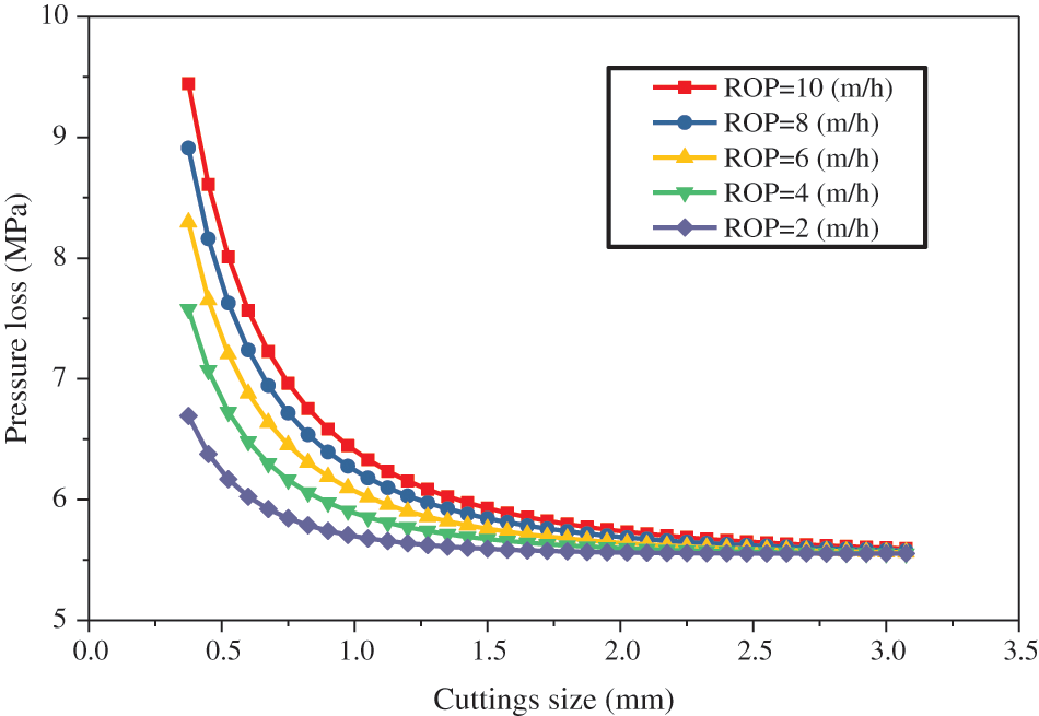
Figure 10: Effects of cuttings size on annular pressure loss for varying ROPs
From the overall trend, the annular pressure loss decreases with increasing drill cuttings size. Moreover, in the range of a large particle size, the reduction in the annular pressure becomes less pronounced. With an identical ROP, the smaller the cuttings size, the greater the annular pressure loss. This is because the small size of the particles results in a large amount of cuttings particles in the annulus, which in turn increases the consistency of the drilling fluid, ultimately leading to an increase in the annular pressure loss. In addition, small-sized cuttings particles are more likely to swell and hydrate when exposed to water-based drilling fluids.
There are still some limitations in this study which need to be further explored. Firstly, the cuttings effects on the rheological parameters of drilling fluid adopted in this study is based on the empirical correlation in the literature, so it is necessary to investigate the effects of different cuttings on the rheological parameters of different types of drilling fluids in the future. Secondly, this study ignored the influence of temperature and pressure on the properties of the drilling fluid in the calculation of pressure loss. Although there are still some shortcomings in this study, a calculation approach is proposed that considers the cuttings effects on the annulus pressure loss, which has important reference value for the accurate calculation of bottomhole pressure.
The effect of cuttings on the pressure loss was evaluated by coupling the cuttings effect on drilling fluid rheology. The main conclusions that can be obtained from this study are as follows:
(1) By introducing the empirical correlations of the rheological parameters and analyzing the pressure effect from cuttings, a pressure loss prediction method was presented for ERW.
(2) Cuttings play a significant role in the annular pressure loss considering cuttings effect both on the density and the rheology of the drilling fluid.
(3) With the drilling fluid flow rate increases, the annular pressure loss increases in the low range of the ROP, while the annular pressure loss first decreases and then increases in the high range of the ROP.
(4) Small-sized cuttings have a greater impact on the annular pressure loss than large-sized cuttings.
Acknowledgement: None.
Funding Statement: This work was supported by the Sinopec Scientific Research Project “Demonstration of Engineering Technology for Ultra-Deep Drilling and Completion in Tarim Basin” (No. P21081-6) and the National Natural Science Foundation of China Project “Mesoscopic Simulation of Dynamic Behavior of Bridging Particles Forfractured Thief Zone” (No. 51604237). The URLs to the Sinopec: http://www.sinopecgroup.com/group; The URLs to the National Natural Science Foundation of China: https://www.nsfc.gov.cn.
Author Contributions: The manuscript was written through the contributions of all authors. All authors have approved the final version of the manuscript.
Conflicts of Interest: The authors declare that they have no conflicts of interest to report regarding the present study.
References
1. Landet, I. S., Pavlov, A., Aamo, O. M. (2013). Modeling and control of heave-induced pressure fluctuations in managed pressure drilling. IEEE Transactions on Control Systems Technology, 21(4), 1340–1351. [Google Scholar]
2. Kiran, R., Salehi, S. (2017). Thermoporoelastic modeling of time-dependent wellbore strengthening and casing smear. Journal of Energy Resources Technology, 139(2), 22903. [Google Scholar]
3. Subramanian, R., Azar, J. J. (2000). Experimental study on friction pressure drop for nonnewtonian drilling fluids in pipe and annular flow. Journal of Physical Chemistry C, 116(6), 2352–2359. [Google Scholar]
4. Taylor, J., Fishburn, T., Djordjevic, O., Sullivan, R. (2011). Velocity modeling workflows for sub-salt geopressure prediction: A case study from the lower tertiary trend, Gulf of Mexico. Geofluids, 11(4), 376–387. [Google Scholar]
5. Vryzas, Z., Kelessidis, V. C., Nalbantian, L., Zaspalis, V., Gerogiorgis, D. I. et al. (2017). Effect of temperature on the rheological properties of neat aqueous wyoming sodium bentonite dispersions. Applied Clay Science, 136(1687), 26–36. [Google Scholar]
6. Vryzas, Z., Kelessidis, V. C. (2017). Nano-based drilling fluids: A review. Energies, 10(4), 540. [Google Scholar]
7. Amani, M., Aljubouri, M. (2012). The effect of high pressures and high temperatures on the properties of water based drilling fluids. Energy Science & Technology, 4(1), 27–33. [Google Scholar]
8. Kok, M. V., Alikaya, T. (2005). Effect of polymers on the rheological properties of KCL/polymer type drilling fluids. Energy Sources, 27(5), 405–415. [Google Scholar]
9. Njobuenwu, D. O., Wobo, C. A. (2007). Effect of drilled solids on drilling rate and performance. Journal of Petroleum Science and Engineering, 55(3), 271–276. [Google Scholar]
10. Liu, Z., Zhou, F., Qu, H., Yang, Z., Zou, Y. S. (2017). Impact of the microstructure of polymer drag reducer on slick-water fracturing. Geofluids, 2017(1), 1–8. [Google Scholar]
11. Du, H., Wang, G., Deng, G., Cao, C. (2018). Modelling the effect of mudstone cuttings on rheological properties of KCl/polymer water-based drilling fluid. Journal of Petroleum Science and Engineering, 170(2), 422–429. [Google Scholar]
12. Li, X., Gao, D., Zhou, Y., Zhang, H., Yang, Y. (2017). Study on the prediction model of the open-hole extended-reach limit in horizontal drilling considering the effects of cuttings. Journal of Natural Gas Science and Engineering, 40(1), 159–167. [Google Scholar]
13. Martins, A. L., Arago, A. F. L., Calderon, A., Leal, R. A. F., Magalhães, J. V. M. (2004). Hydraulic limits for drilling and completing long horizontal deepwater wells. SPE International Thermal Operations & Heavy Oil Symposium & Western Regional Meeting, Bakersfield. [Google Scholar]
14. Ma, Q. T., Ge, P. F., Wang, X. Y., Jia, J. H. (2013). Key technology of shale gas horizontal drilling in well HF-1 of fuye. China Petroleum Machinery, 41(8), 107–110. [Google Scholar]
15. Sorgun, M., Ozbayoglu, M. (2011). Predicting frictional pressure loss during horizontal drilling for non-Newtonian fluids. Energy Sources, Part A: Recovery, Utilization, and Environmental Effects, 33(7), 631–640. [Google Scholar]
16. Baujard, C., Hehn, R., Genter, A., Teza, D., Baumgärtner, J. et al. (2017). Rate of penetration of geothermal wells: A key challenge in hard rocks. 42nd Workshop on Geothermal Reservoir Engineering, Stanford. [Google Scholar]
17. Monazami, M., Hashemi, A., Shahbazian, M. (2012). Drilling rate of penetration prediction using artificial neural network: A case study of one of Iranian Southern oil fields. Journal of Oil & Gas Business, 6(6), 21–31. [Google Scholar]
18. Capo, J., Yu, M., Miska, S. Z., Takach, N., Ahmed, R. (2004). Cuttings transport with aqueous foam at intermediate inclined wells. SPE/ICoTA Coiled Tubing Conference and Exhibition, Richardson, Society of Petroleum Engineers. [Google Scholar]
19. Chien, S. F. (1969). Annular velocity for rotary drilling operations. International Journal of Rock Mechanics & Mining Sciences & Geomechanics Abstracts, 9(3), 403–416. [Google Scholar]
20. Millheim, K. K., Tulga, S. S. (1982). Simulation of the wellbore hydraulics while drilling, including the effects of fluid influxes and losses and pipe washouts. SPE Annual Technical Conference and Exhibition, Richardson, Society of Petroleum Engineers. [Google Scholar]
21. Wang, H., Liu, X. (1995). Analysis of annular pressure losses in horizontal section. West-China Exploration Engineering, 7(6), 25–28. [Google Scholar]
22. Haige, W., Xisheng, L., Gang, D. (1993). The model of cuttings bed thickness in horizontal well section. Journal of the University of Petroleum, China, 17(3), 25–32. [Google Scholar]
23. Bailey, W., Peden, J. (2000). A generalized and consistent pressure drop and flow regime transition model for drilling hydraulics. SPE Drilling & Completion, 15(1), 44–56. [Google Scholar]
24. Kelessidis, V. C., Dalamarinis, P., Maglione, R. (2011). Experimental study and predictions of pressure losses of fluids modeled as Herschel-Bulkley in concentric and eccentric annuli in laminar, transitional and turbulent flows. Journal of Petroleum Science and Engineering, 77(3–4), 305–312. [Google Scholar]
Appendix A. Equations for cuttings concentration
The feed rate of cuttings qs is calculated as follows:
where Ab is the area cut by bit, m2; ROP is the rate of penetration, m/s; ϕ is the porosity of cuttings, dimensionless.
FT is the cuttings transport ratio, dimensionless, and is defined by
where the drilling fluid velocity va is given by
where Aa is the cross-section area of annulus, m2.
Due to the extremely complicated flow behavior of the drilling fluid in the wellbore, the cuttings slip velocity vsl is obtained only under idealized conditions. The empirical correlation of the cuttings slip velocity can be expressed by Eq. (A-4) [12].
where μa, the apparent viscosity, is given by
The cuttings slip rate, qsl, is defined as
then from Eqs. (A-3), (A-4) and (A-7), the cuttings transport ratio is given as
Combining the Eqs. (A-1) and (A-7), the following formula is obtained:
Solving Eq. (A-8), the cuttings concentration is obtained as follows:
Since qsl and Cs are cross linked, a numerical method (trial and error method) is used to obtain the value of Cs.
Appendix B. Equations for pressure loss
Frictional pressure loss for the vertical section and the small inclination section is defined as
where vv is the average annular fluid velocity, m/s; Lv is the length of vertical section and small inclination section, m. Annular friction coefficient fv can be referred to the literature [11].
Reynolds number Re is often used to distinguish between laminar flow and turbulent flow in engineering. For the Herschel-Bulkley model fluid, the generalized Reynolds number is estimated in Eq. (B-2).
where Re
In the deviated section, the cuttings can easily accumulate in the annulus to form a cuttings bed under gravity. It is therefore necessary to add a correction to the annular pressure loss calculation when the cuttings are involved. In addition, the eccentricity of the drill string also has an effect on the annular pressure loss. Therefore, the correction factor considering eccentricity should also be added.
Considering the effects of cuttings bed and drill string eccentricity, a correction factor Rdi can be defined as
where Rc is the correction factor for cuttings bed and Re is the correction factor for drill string eccentricity. Rc can be obtained from Eq. (B-4) [19].
where ρs and ρm are the cuttings density and drilling fluid density, g/cm³.
The friction coefficient fd considering the effects of cuttings can be calculated by Eq. (B-5).
The cuttings bed thickness hc is expressed by Eq. (B-6) [20].
where N is the rotation speed of drill pipe, rpm; vacj is the cuttings injection velocity, kg/min; and ε is dimensionless eccentricity, which is calculated by Eq. (B-7) [21].
Annular pressure loss in deviated sections with correction factor is given by [22]
where Ldi is the length of the ith inclination section, m. fd is frictional factor in the deviated sections, dimensionless.
Similar to the deviated sections, in the horizontal section, the pressure loss Δph is obtained from Eq. (B-8). Rh is referred to in the literature [23,24].
where Rh is the eccentric coefficient for horizontal section, which according to the flow regime, can be estimated as Eqs. (B-10) and (B-11) [24].
Appendix C. Input data for annular pressure loss model with cuttings effects
Based on the presented method for annular pressure loss prediction, a three-stage horizontal well is used as a case to analyze the sensitivity of the parameters [12]. Detailed data are presented in Tables 1 and 2.


Cite This Article
 Copyright © 2023 The Author(s). Published by Tech Science Press.
This work is licensed under a Creative Commons Attribution 4.0 International License , which permits unrestricted use, distribution, and reproduction in any medium, provided the original work is properly cited.
 Downloads
 Citation Tools