
 Submit a Paper
 Propose a Special lssue
 Open Access
ARTICLE
Analysis of Friction and Heat Transfer Characteristics of Tubes with Trapezoidal Cut Twisted Tape Inserts
Department of Mechanical Engineering, Oriental University, Indore, 453555, India
* Corresponding Author: Shrikant Arunrao Thote. Email:
(This article belongs to the Special Issue: Advances in Fluid Dynamics and Functional Materials)
Fluid Dynamics & Materials Processing 2023, 19(3), 711-722. https://doi.org/10.32604/fdmp.2022.021651
Received 26 January 2022; Accepted 16 March 2022; Issue published 29 September 2022
 View Full Text
 Download PDF
Abstract
The thermo-hydraulic properties of circular tubes with a twisted tape inside (used accordingly to induce turbulence and enhance heat transfer through the tube wall) are described for Reynolds Numbers ranging from 830 to 1990. Tapes twisted with the three distinct twist ratios are considered, namely, 6, 4.4 and 3. Air is used as the working fluid in several tests. For the sake of comparison, the standard tube with no insert is also examined. It is shown that in the presence of the twisted tape, the ‘frictional factor’, ‘Nusselt Number’ and the ‘thermal performance factor’ are much higher than those obtained for the plain tube. Moreover, the tapes having the lowest twist ratio, i.e., 3, are more effective than the others in terms of heat transfer augmentation. The ‘thermal performance factor’ is greater than one for all the twisted tapes used in the experiments, which confirms the enhanced performances of the heat exchanger and the related savings in terms of total energy.Keywords
Nomenclature
| Nu | Nusselt number |
| Re | Reynolds number |
| Pr | Prandtl number |
| f | Friction factor |
| Nup | Nusselt number of plane tube |
| fp | Friction factor of plane tube |
| d | Diameter of the tube in mm (Internal) |
| L | Length of the tube in mm |
| η | Performance ratio |
The process of exchange of heat is widely used in engineering and in the industry. A heat exchanger is difficult to design as it requires a precise study of pressure drop, along with the rate of heat transfer estimates and cost and performance considerations [1]. A successful heat exchanger will have a small body while achieving a high rate of heat transfer with low pumping power [2]. With the increasing price of materials and power it is imperative that an efficient heat exchange should be developed [3]. Additionally, heat exchanger reduction is sometimes required in specialized applications, such as space applications, where heat transmission must be enhanced. Advances in technology and specialized applications need more accurate and efficient equipment to produce accurate and useful results. For example the OTEC facility (Ocean Thermal Energy Conversion) requires a heat exchanger with the surface area of heat transfer of 10,000 sq.m/MW [4]. The wear and tear of the heat exchanger results in fouling or scaling, which further increases the barrier to heat transmission [5]. Similar problems are encountered when heat exchangers are used in other sectors for different applications. Some application require heat exchangers to work with oil and gases, which are known to be poor fluids of thermal conductivity, some are even employed at desalination facilities [6]. One of the approaches for increasing the rate of heat transfer is to generate disturbance on the flow of the fluid (boundary layers of thermal and breaking of the viscosity). The desired effect is accompanied with an increase in pumping power and hence it increases cost [7]. As a result, in recent years, while utilizing the power of pumping, in the existing heat exchanger; several new methods for achieving the desired rate of transferring of heat are devised.
Out of many like these, the passive enhancement of heat transfer techniques is becoming popular. It is utilized widely to increase the performance of a wide range of heat carrying equipment. The method to bring this about is by fully utilizing some inserts, which are in the passage in which the fluid flows, thereby inducing turbulence flow which improves the convective rate of transferring heat [8]. These passive enhancement methods are more advantageous than active transfer enhancement methods. The added advantage is that they may be used directly in heat exchanger with or without extra pumping power. Several types of research on the passive transfer of heat improvement methods are published in the current decade. For the improvement of the performance of the circular thermal tube, researchers [7,8] have employed circularly perforated rings and solid hollow circular discs. Using numerous tapes that are twisted and inserts with solid rings, some [9] studied the heat transfer enhancement experimentally. The ‘Thermal Enhancement Factor’ (TEF) was seen between 1.46 and 1.61.
The transfer of heat occurs in the flow of the laminar domain in a variety of applications of engineering and because of the transfer of heat coefficients which are often lower, the augmentations methods of the passive transfer of the heat are usually used [10]. Several devices employ a way of increasing the fluid’s residence time staying in the system by creating the motion that is swirling and thus the improvement of the coefficient while there is a transfer of heat, the consequences related to the rise of the pressure drop [11]. Erfanian Nakhchi et al. [12] investigated the effects of the intensity of the holes on the velocity and temperature contours and found that the thermal performance is highly considered with the perforated turbulators than with the VRW inserts and it also augments the mixing of the fluid and transfers the heat from the pipe walls to the core of the tube due to the flow generated by the PVRW. By reducing the DR from 0.4 to 0.13 the enhancement of heat transfer occurs by 25.2% and also for the heat exchangers with vortex generators with N = 14 and DR = 0.26, the highest η = 2.25 (thermal efficiency) obtained at Re = 5000. The output of rotated inclined elliptical (RIE) inserts on heat exchanger pipes for heat transfer and the thermal performance factor of double-pipe were investigated [13]. RIE turbulators improve heat transfer by up to 30.7 percent when compared to non-rotated elliptic (NRIE) turbulators, and for the RIE turbulators with β = 90, dp/b = 0.250, and α = 25° the highest thermal performance factor of 2.23 was achieved. When NRIE vortex generators with dp = 1.5 mm are used, the heat transfer coefficient is improved by 59.95 percent when compared to typical non-rotated louvered strips. It was discovered that using DPIE turbulators increased the Nusselt number by 217.4 percent when compared to the tube without vortex generators. The maximum thermal efficiency parameter of 1.849 was obtained for the DPIE vortex generators with d/b = 0.25 and α = 25. A 14.0 percent increase in friction factor was also observed for the DPIE insert with d/b (0.25), and the heat transfer increased by 39.4 percent for the DPIE insert with d/b (0.25) [14]. The separation of the thermal boundary layer is the primary cause of heat transfer enhancement [15].
Apart from the insert designs, the thermo-hydraulic behavior of an insert is mostly determined by the conditions of the flow (turbulent or laminar). The following are the main findings of all researchers in connection to various inserts and flow [16].
2.1 Tape Twisted in the Laminar Flow
The laminar flow of the thermal resistance is not restricted to any tiny region, the tape that is twisted mixes and efficiently inserts in the bulk flow and performs better in the laminar flow than the other inserts. Twisted tape performance, on the other hand, is influenced by fluid characteristics such as the ‘Prandtl number’. If the ‘Prandtl number’ is large, such as Pr = 30, the twisted tape will not perform whereas the other inserts such as the coil of a wire increases in terms of thermo-hydraulic performance. Short-length tape that is twisted outperforms twisted tape which is full length in terms of continuous pumping power. Twisted tape can be utilized successfully to increase heat transfer by the construction of the laminar flow of the heat exchanger [17].
2.2 Tape Twisted in the Turbulent Flow
Inside the turbulent flow, the twisted tape effectively upgrades to the particular range of the Reynolds number, but not beyond that. The tape that is twisted is ineffective in turbulent flow as compared to the wire coil as it causes a high-pressure drop and it stops the flow. As a result, in turbulent flow, the twisted tape has a ‘thermo-hydraulic performance’ that is inferior to that of a wire coil. As a result, it can be stated that the coil of the wire is a favorable option in the turbulent flow for compact heat exchanger construction. The turbulent flow, which has a short length of tape that is twisted, produces good behavior of thermo-hydraulic performance when it is compared to a twisted tape that has the full length [18].
2.3 Laminar Flow in the Wire Coil
The transmission heat rate of the coil in the wire, in the laminar flow is considerably increased. The performance, however, is determined by the ‘Prandtl number’. If the ‘Prandtl number’ is large, the performance coil in the wire is favorable because the thick layer of the thermal boundary is modest as compared to the boundary layer of hydrodynamic for a high Prandtl number, and the coil readily breaks this thick boundary layer. As a result, both the pressure and the heat transmission decrease are significant [19].
2.4 Turbulent Flow in the Wire Coil
The wire coil in the turbulent flow has effectively improved the transmission of heat. The turbulent flow performs better than the laminar flow. The wire coil outperforms twisted tape in the turbulent flow, in terms of thermo-hydraulic performance [20].
Other than the tape that is twisted and the coil of the wire, passive techniques such as the fins, dimples, and ribs can be used to improve heat transmission in a flow. In turbulent flow, these approaches are typically more effective than in laminar flow.
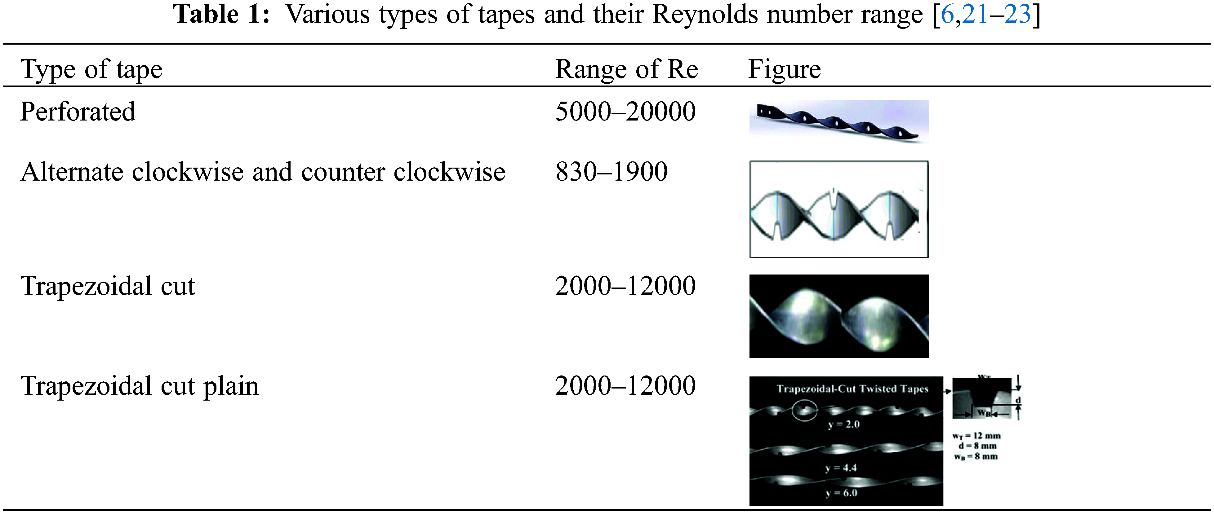
In heat exchangers, inserts play an essential function as turbulence promoters. In a heat exchanger, there are a variety of ways for producing turbulence in the flow. A large number of studies have been conducted by several researchers that are creating the turbulence inside the flow field of a heat exchanger. Heat exchangers are also more compact with inserts. The following are some examples of twisted tapes: 1. Tapes with twist ratio 2. Perforated Tapes 3. Cut Tapes 4. Double twist tapes 5. Dimple tapes 6. Coupling 7. V-cut tapes 8. V-finned 9. Tapered 10. Clockwise twisted 11. Non-Uniform tapes 12. Continuous spaced 13. Trapezoidal 14. Quadruple cut 15. U cut 16. Multiple quadruple 17. Double v-ribbed 18. Perforated and helical, etc. The description of a few tapes along with the Reynolds range is given in Table 1 below [6,21–23].
Two concentric tubes are placed one within the other in this setup as shown in Fig. 2. The tube made of copper with an internal diameter of 28.5 mm and a length of 2000 mm allows hot air to travel through the tube while cold air flows in the opposite direction through the annulus. The experimental setup includes two rota-meters for measuring cold and hot air flow rates, as well as temperature readings at the input and exit. As shown in Fig. 1, 04 temperature sensors (02 on each side) detect the temperature of hot air at the inlet and outlet, whereas 02 (01 on each side) measures the temperature of cold air at the inlet and outflow. As the conditions of steady-state are attained in the case of the plain tube, a U tube manometer detects the reduction in pressure, while RTDs (Resistance Temperature Detector) measure the temperatures of hot and cold air at the intake and exit.
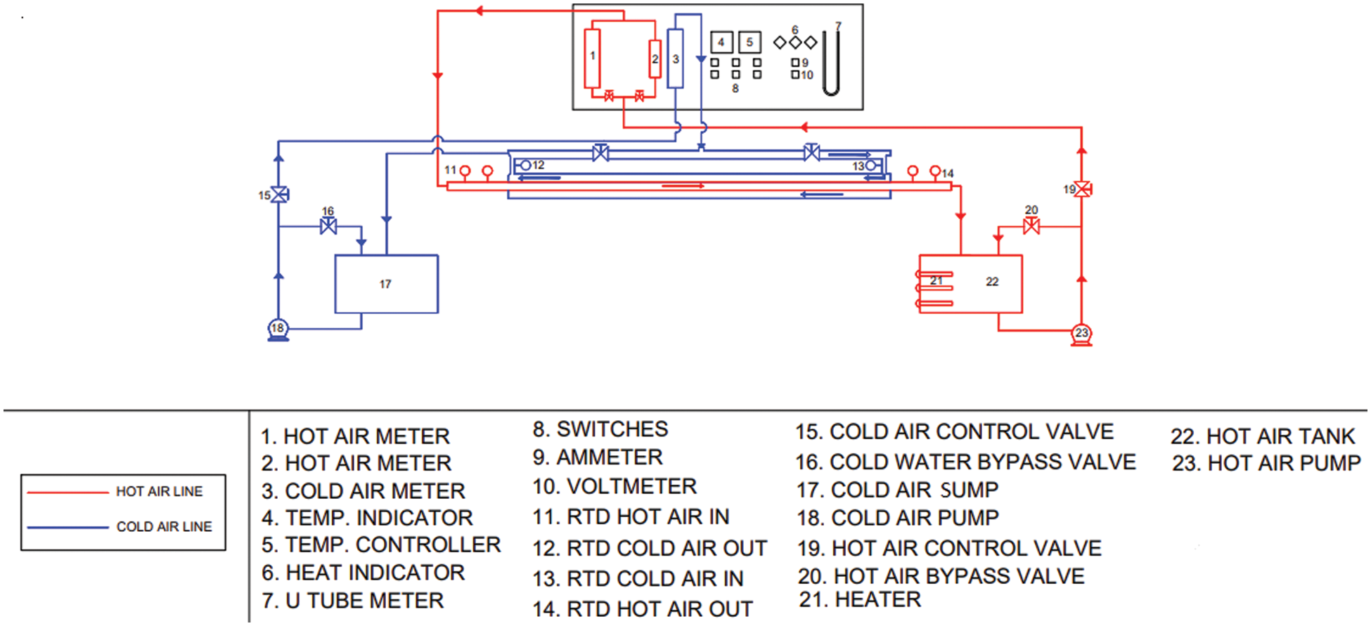
Figure 1: Setup of the experiment
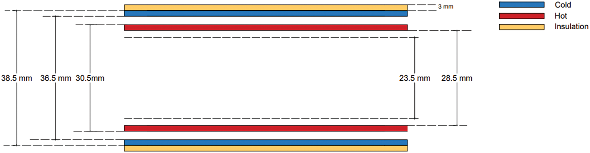
Figure 2: Dimensions of pipe
The tests were carried out using twisted tapes displayed in Fig. 3 with twist ratios of 3, 4.4, and 6 (y = 54, 79.2 and 108 mm, and w = 18 mm), with Reynolds numbers ranging from 830 to 1990, and air as the working fluid. For the laminar regime, the reference ‘Nusselt number (Nup)’ and ‘friction factor (fp)’ taken are ‘Nup = 48/11 and fp = 64/Re’, respectively. Eqs. (1)–(3) [24] are used to determine Nu, f, and η with a twisted tape insert.
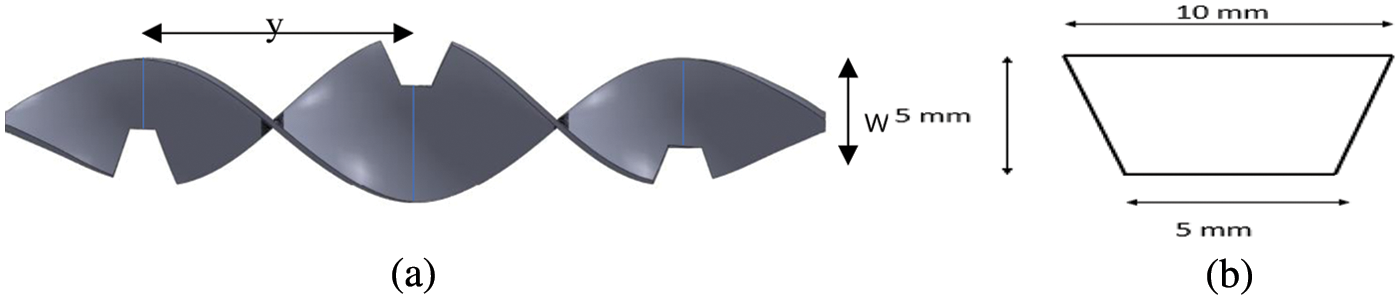
Figure 3: (a) Twisted tape insert (b) Dimensions of the trapezoidal-section
4.1 Effect of an Insert on Heat Transfer
Nusselt Number (Nu) is defined as the ratio of convective heat transfer to the conductive heat transfer in a fluid subjected to boundary conditions. From Table 2, we notice that the value of ‘Nusselt number (Nu)’ appears to grow significantly as Reynolds Number rises, indicating an increase in convective heat transfer. Nusselt number rises as Reynolds number rises across the range studied (laminar regime). It is also discovered that greater y/w ratios are associated with lower Nu levels, as shown in Fig. 4.
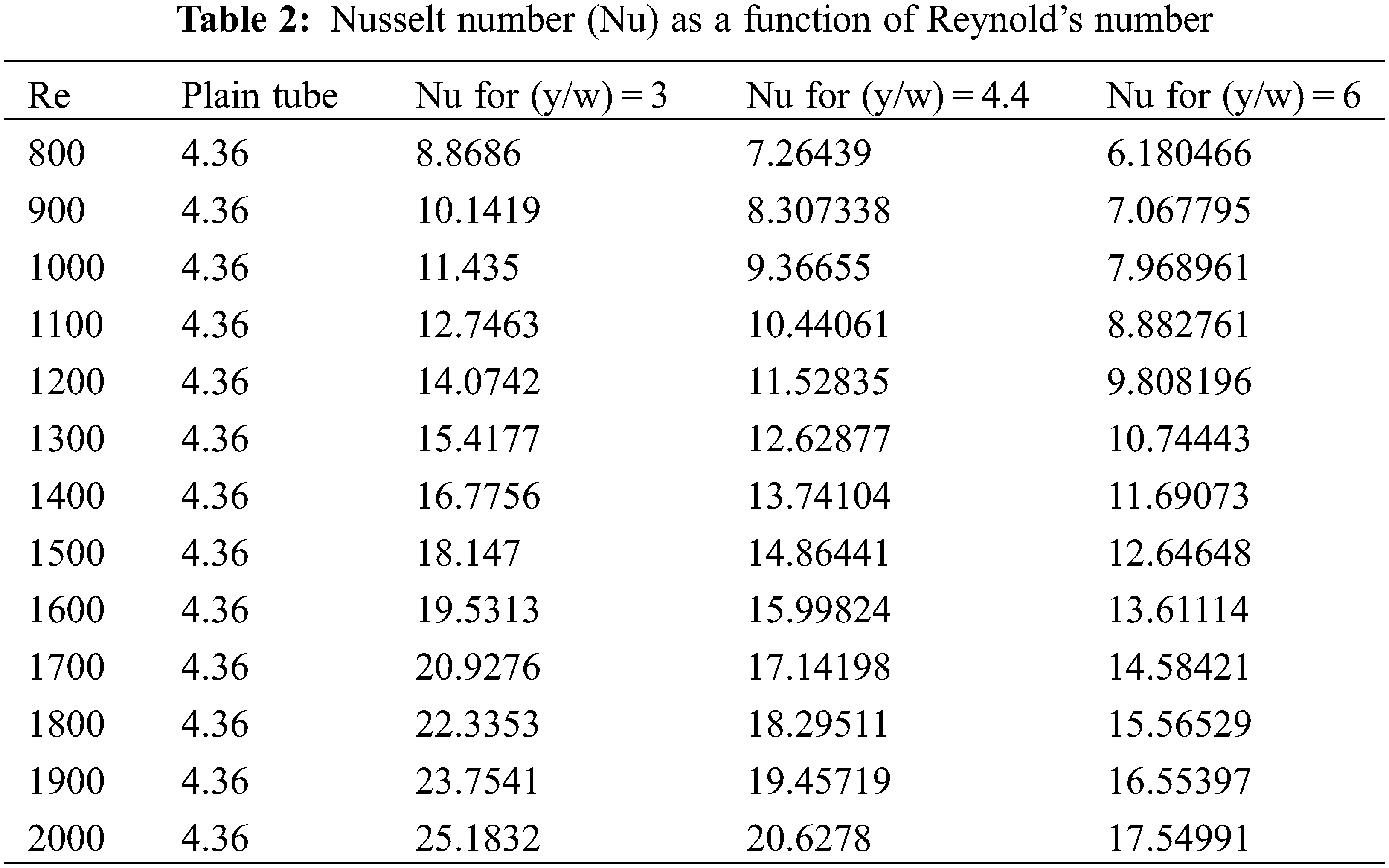
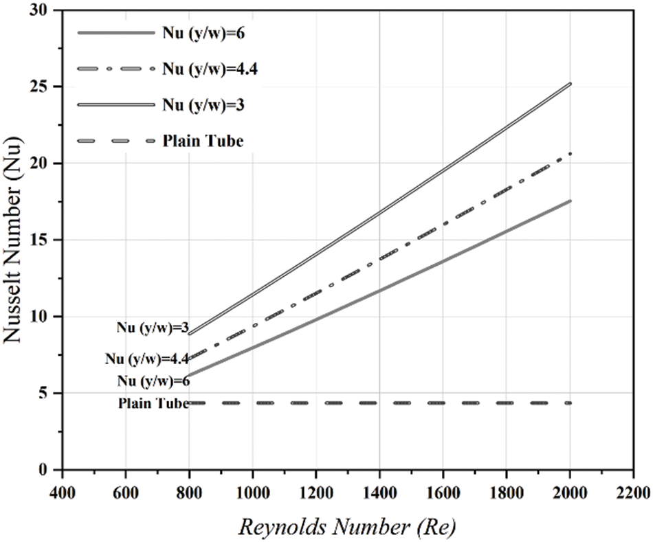
Figure 4: Validation of Nusselt number vs. Reynolds number for plain tube with an insert
Fig. 4 also indicates that the Nusselt Number for an insert is greater than the plain tube, because insert causes the flow to spiral along the tube length and disturbs the entire flow which tends to increase the rate of heat transfer. Also, it was deduced that a higher rate of heat transfer given by the lower twist ratio than the higher twist ratio was because of the intensity of turbulence and the length of flow obtained which were higher for the lower twist ratio than the higher twist ratio.
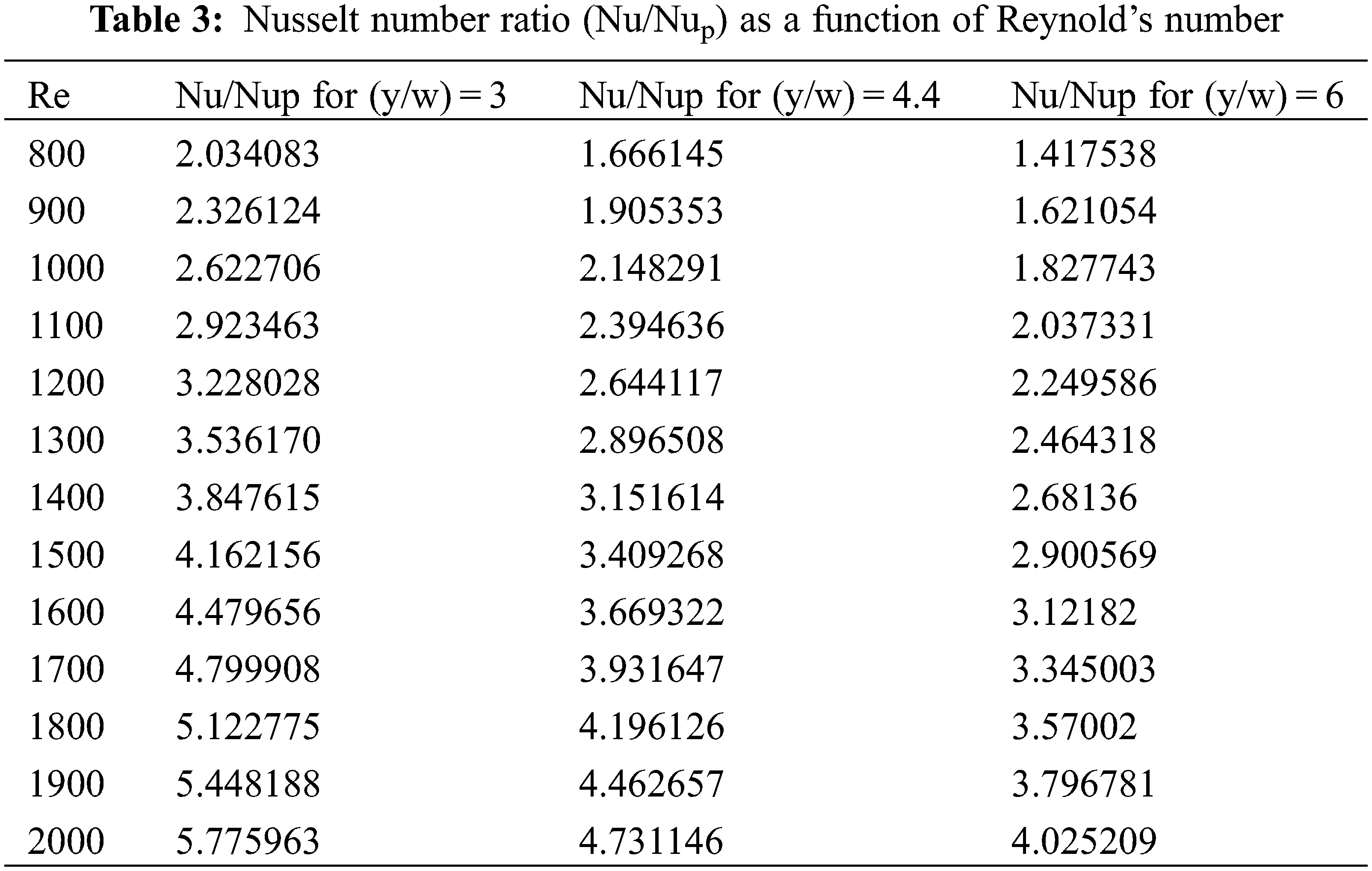
The ‘Nusselt number ratio (Nu/Nup)’ increases with the increase in ‘Reynolds Number’, as illustrated in Fig. 5, across the range examined (laminar regime) and the values are tabulated in Table 3 for the different twist ratio.
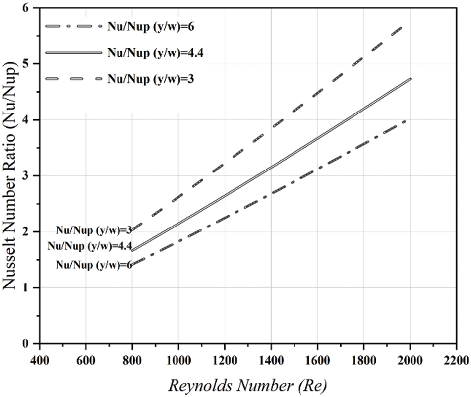
Figure 5: Variation of Nu/Nup with Re
4.2 Effect of an Insert on Friction Factor
The friction factor is defined as a function of Reynold’s number and relative roughness. There is the change of friction factor with the ‘Reynolds Number’ for the tube with tape insert as shown in Fig. 6. From Table 4 it can be seen that the friction factors of the tube with y/w = 3 appears to be higher than the one of a simple tube.
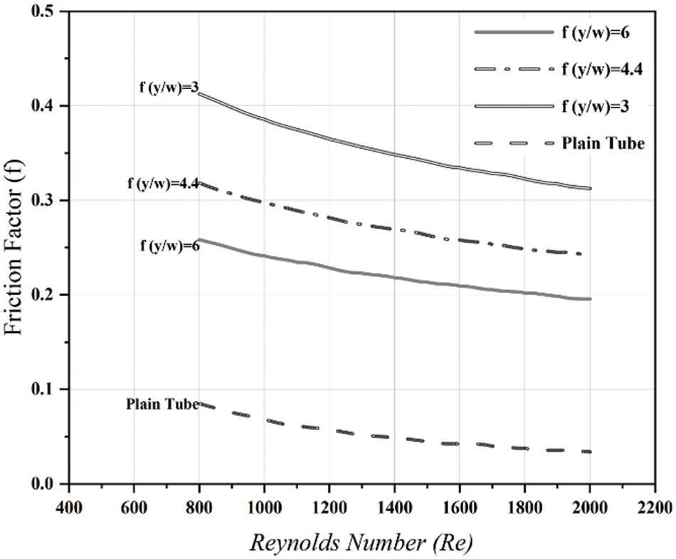
Figure 6: Validation of friction factor vs. Reynolds number for plain tube with an insert
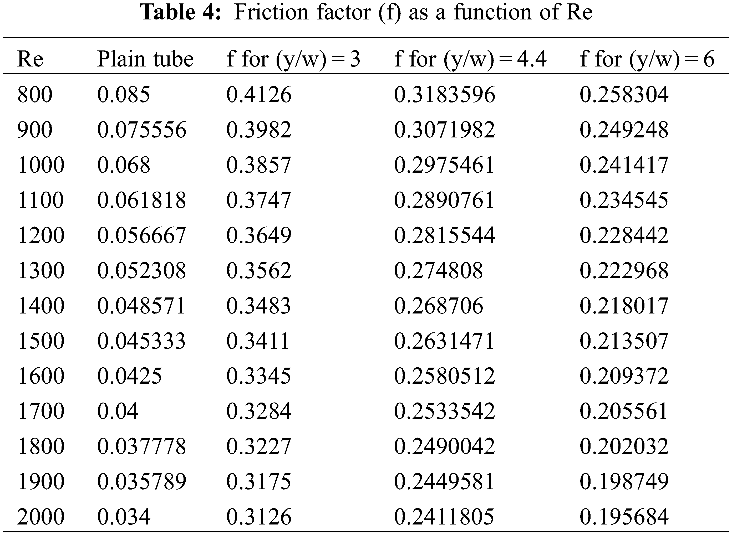
Fig. 6 also depicts the decrease of friction factor with an increase in Reynold’s Number. For every insert, the friction factor is higher than that found in the plain tube. For the lowest twist ratio; it tends to get higher friction factor as there is decrease in twist ratio, with an increase in swirl flow which thus provides the maximum tangential contact between the tube wall surface and secondary flow.
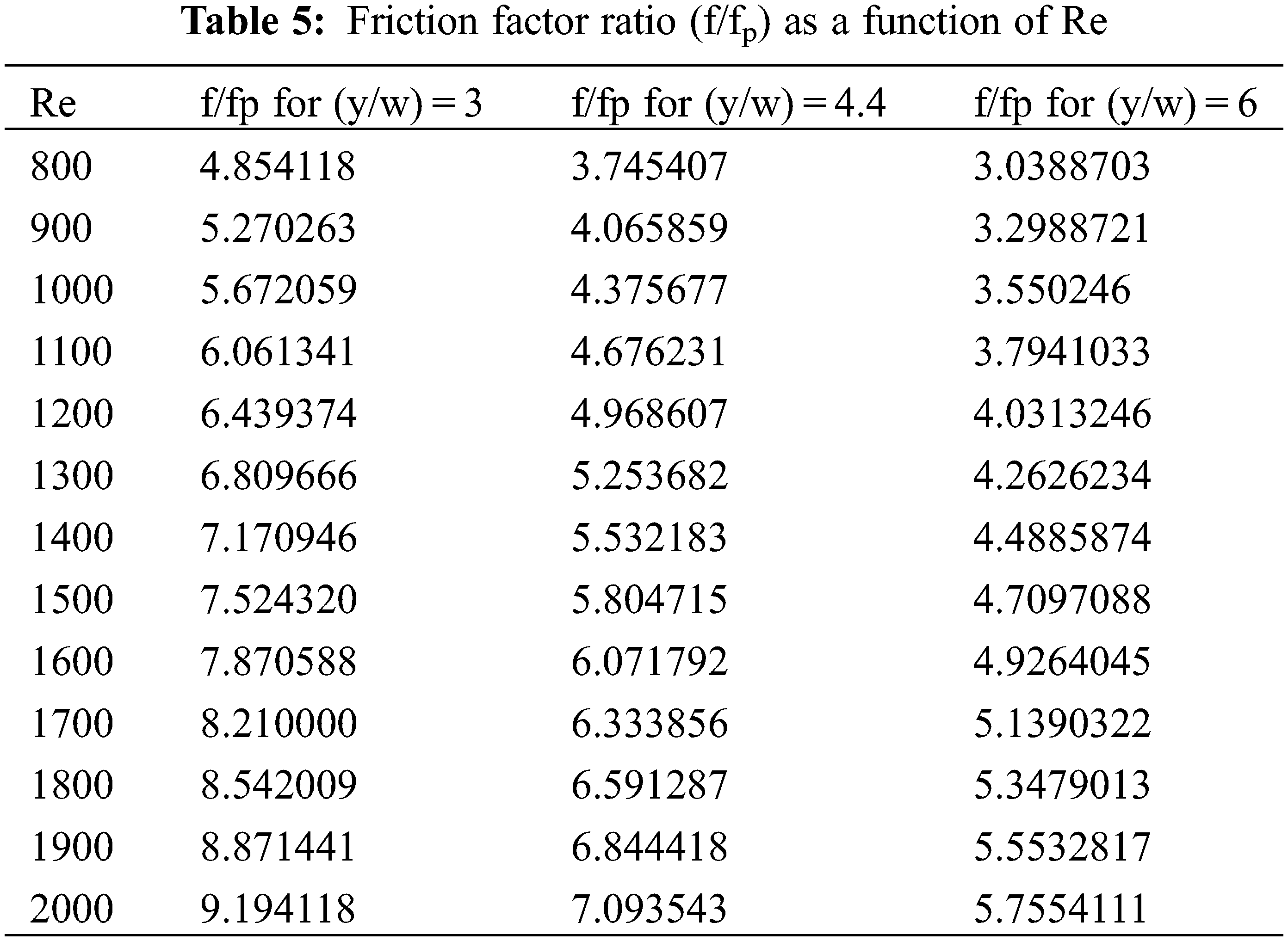
As demonstrated in Fig. 7, the “friction factor ratio (f/fp)” increases with the “Reynolds number”. We tabulated the friction factor ratio for the different twist ratio in Table 5.
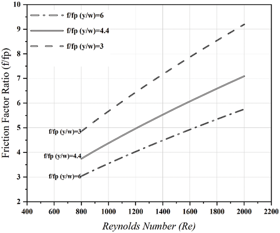
Figure 7: Variation of f/fp with Re
4.3 Analysis of the Performance of Heat Exchanger
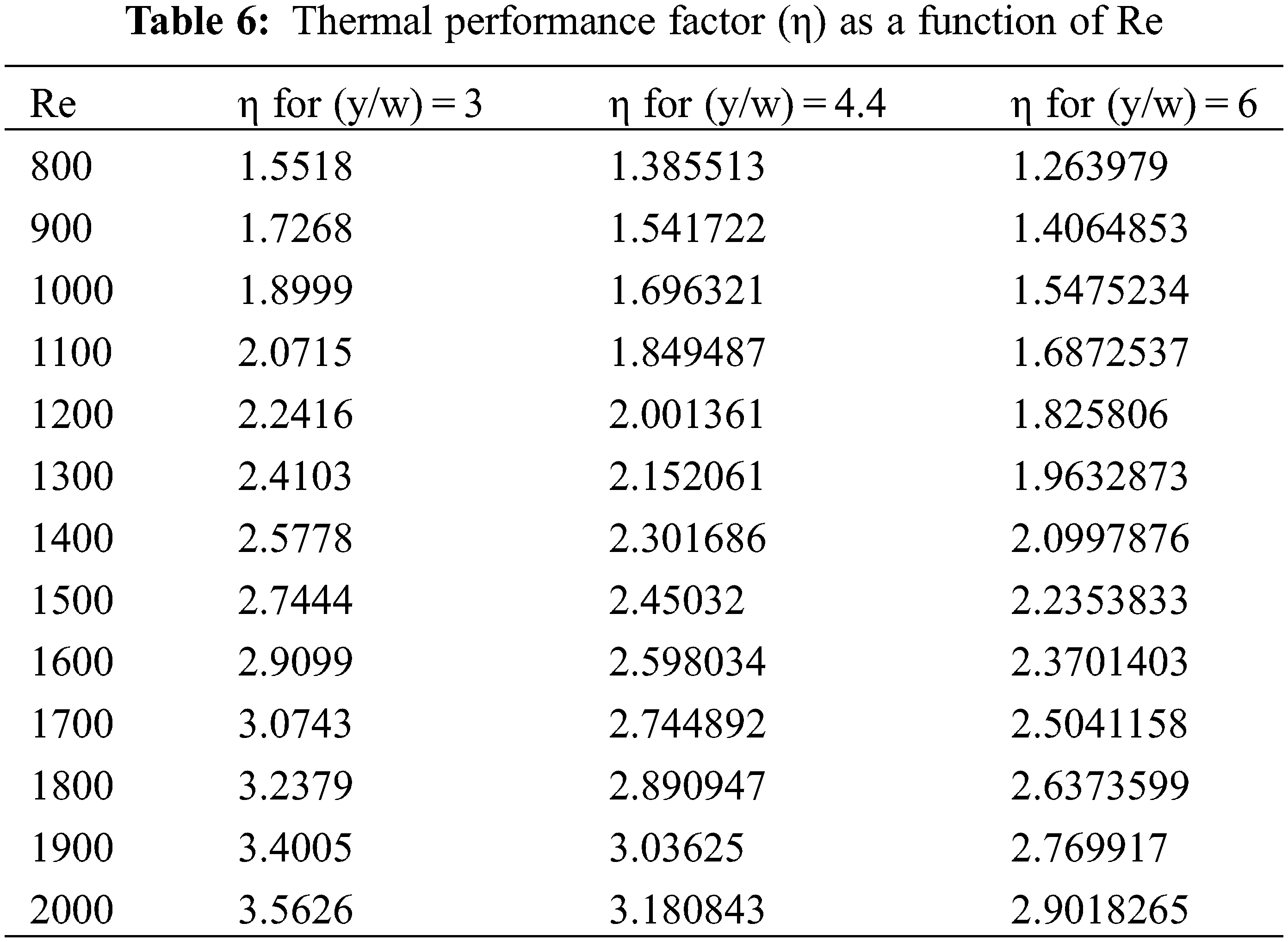
The thermal performance/enhancement factor is defined as the ratio of the heat transfer coefficient of an augmented surface to that of a smooth surface. The final criteria for evaluating the practical usage of twisted tapes is the thermal performance factor (η). Fig. 8 depicts the change in the performance factor of thermal with the ‘Reynolds number’ of the tubes with the twist ratios 3, 4.4, and 6 falling under the variation of 1.5518–3.5626, 1.385513–3.180843 and 1.263979–2.9018265 for an insert observed in Table 6 and it indicates that performance ratio for all the cases are higher than one (unity), it means that the use of enhancement is valuable towards the point of saving of total energy.
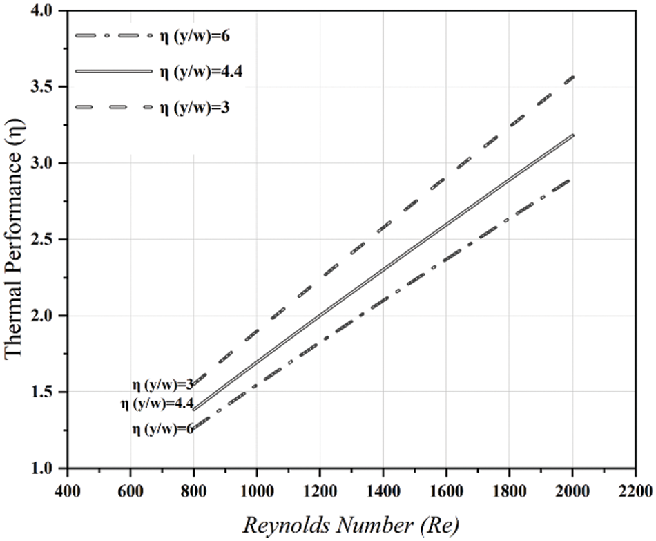
Figure 8: η V/s Re for tape with an insert of twist ratios 3, 4.4, and 6
In the laminar flow regime, the effects of twisted tape on ‘heat transfer (Nu)’, ‘friction factor (f)’ and ‘thermal performance (η)’ are discussed. The following are the key findings:
1. The Nusselt number (Nu) associated with the tape insert is substantially greater than that associated with the normal tube under comparable conditions-(y/w = 3) gives a greater Nu than (y/w = 6) in the range studied.
2. Twisted tapes provide a significantly higher thermal efficiency factor, which improves as the twist ratio decreases. For the insert, the heat transfer rate for the twist ratios 3, 4.4, and 6 are higher than the plain tube without the insert. It means that the intensification is valuable for energy saving.
3. The friction factor produced by a tape insert is larger than that induced by a plain tube, and it rises as the twist ratio decreases.
Acknowledgement: The authors thank the Manager and Assistant Manager of SGP Instruments & Control, AMBERNATH (E). DIST:-THANE (M.S.)-INDIA for giving us permission for experimentations.
Funding Statement: The authors received no specific funding for this study.
Conflicts of Interest: The authors declare that they have no conflicts of interest to report regarding the present study.
References
1. Pan, M., Bulatov, I., Smith, R., Kim, J. K. (2012). Novel MILP-based iterative method for the retrofit of heat exchanger networks with intensified heat transfer. Computers & Chemical Engineering, 42, 263–276. DOI 10.1016/j.compchemeng.2012.02.002. [Google Scholar] [CrossRef]
2. Safikhani, H., Abbasi, F. (2015). Numerical study of nanofluid flow in flat tubes fitted with multiple twisted tapes. Advanced Powder Technology, 26(6), 1609–1617. DOI 10.1016/j.apt.2015.09.002. [Google Scholar] [CrossRef]
3. Eiamsa-ard, S., Promvonge, P. (2010). Performance assessment in a heat exchanger tube with alternate clockwise and counter-clockwise twisted-tape inserts. International Journal of Heat and Mass Transfer, 53(7–8), 1364–1372. DOI 10.1016/j.ijheatmasstransfer.2009.12.023. [Google Scholar] [CrossRef]
4. Dhamane, N. B., Nalawade, D. B., Dange, M. M. (2014). Performance analysis of wavy twisted tape insert for heat transfer in a circular tube. International Journal for Technological Research in Engineering, 1(6), 367–371. [Google Scholar]
5. Boonloi, A., Jedsadaratanachai, W. (2016). Turbulent forced convection and heat transfer characteristic in a circular tube with modified-twisted tapes. Journal of Thermodynamics, 2016, 1–16. DOI 10.1155/2016/8235375. [Google Scholar] [CrossRef]
6. Dewan, A., Mahanta, P., Raju, K. S., Kumar, P. S. (2004). Review of passive heat transfer augmentation techniques. Proceedings of the Institution of Mechanical Engineers, Part A: Journal of Power and Energy, 218(7), 509–527. DOI 10.1243/0957650042456953. [Google Scholar] [CrossRef]
7. Kumar, A., Chamoli, S., Kumar, M., Singh, S. (2016). Experimental investigation on thermal performance and fluid flow characteristics in circular cylindrical tube with circular perforated ring inserts. Experimental Thermal and Fluid Science, 79, 168–174. DOI 10.1016/j.expthermflusci.2016.07.002. [Google Scholar] [CrossRef]
8. Kumar, A., Chamoli, S., Kumar, M. (2016). Experimental investigation on thermal performance and fluid flow characteristics in heat exchanger tube with solid hollow circular disk inserts. Applied Thermal Engineering, 100, 227–236. DOI 10.1016/j.applthermaleng.2016.01.081. [Google Scholar] [CrossRef]
9. Singh, V., Chamoli, S., Kumar, M., Kumar, A. (2016). Heat transfer and fluid flow characteristics of heat exchanger tube with multiple twisted tapes and solid rings inserts. Chemical Engineering and Processing: Process Intensification, 102, 156–168. DOI 10.1016/j.cep.2016.01.013. [Google Scholar] [CrossRef]
10. Kumar, P., Kumar, A., Chamoli, S., Kumar, M. (2016). Experimental investigation of heat transfer enhancement and fluid flow characteristics in a protruded surface heat exchanger tube. Experimental Thermal and Fluid Science, 71, 42–51. DOI 10.1016/j.expthermflusci.2015.10.014. [Google Scholar] [CrossRef]
11. Sheikholeslami, M., Gorji-Bandpy, M., Ganji, D. D. (2016). Experimental study on turbulent flow and heat transfer in an air to water heat exchanger using perforated circular-ring. Experimental Thermal and Fluid Science, 70, 185–195. DOI 10.1016/j.expthermflusci.2015.09.002. [Google Scholar] [CrossRef]
12. Nakhchi, M. E., Rahmati, M. T. (2020). Turbulent flows inside pipes equipped with novel perforated V-shaped rectangular winglet turbulators: Numerical simulations. Journal of Energy Resourses Technology, 142(11), 112106. DOI 10.1115/1.4047319. [Google Scholar] [CrossRef]
13. Nakhchi, M. E., Hatami, M., Rahmati, M. (2021). Experimental evaluation of performance intensification of double-pipe heat exchangers with rotary elliptical inserts. Chemical Engineering and Processing-Process Intensification, 169, 108615. DOI 10.1016/j.cep.2021.108615. [Google Scholar] [CrossRef]
14. Nakhchi, M. E., Hatami, M., Rahmati, M. (2021). Experimental investigation of performance improvement of double-pipe heat exchangers with novel perforated elliptic turbulators. International Journal of Thermal Sciences, 168, 107057. DOI 10.1016/j.ijthermalsci.2021.107057. [Google Scholar] [CrossRef]
15. Nakhchi, M. E., Hatami, M., Rahmati, M. (2021). Effects of CuO nano powder on performance improvement and entropy production of double-pipe heat exchanger with innovative perforated turbulators. Advanced Powder Technology, 32(8), 3063–3074. DOI 10.1016/j.apt.2021.06.020. [Google Scholar] [CrossRef]
16. Abolarin, S. M., Everts, M., Meyer, J. P. (2019). Heat transfer and pressure drop characteristics of alternating clockwise and counter clockwise twisted tape inserts in the transitional flow regime. International Journal of Heat and Mass Transfer, 133, 203–217. DOI 10.1016/j.ijheatmasstransfer.2018.12.107. [Google Scholar] [CrossRef]
17. Manglik, R. M., Bergles, A. E. (1993). Heat transfer and pressure drop correlations for twisted-tape inserts in isothermal tubes: Part II—Transition and turbulent flows. Journal of Heat Transfer, 115(4), 890–896. DOI 10.1115/1.2911384. [Google Scholar] [CrossRef]
18. Jedsadaratanachai, W., Jayranaiwachira, N., Promvonge, P. (2015). 3D numerical study on flow structure and heat transfer in a circular tube with V-baffles. Chinese Journal of Chemical Engineering, 23(2), 342–349. DOI 10.1016/j.cjche.2014.11.006. [Google Scholar] [CrossRef]
19. Zheng, N., Liu, P., Shan, F., Liu, J., Liu, Z. et al. (2016). Numerical studies on thermo-hydraulic characteristics of laminar flow in a heat exchanger tube fitted with vortex rods. International Journal of Thermal Sciences, 100, 448–456. DOI 10.1016/j.ijthermalsci.2015.09.008. [Google Scholar] [CrossRef]
20. Bartwal, A., Gautam, A., Kumar, M., Mangrulkar, C. K., Chamoli, S. (2018). Thermal performance intensification of a circular heat exchanger tube integrated with compound circular ring–metal wire net inserts. Chemical Engineering and Processing-Process Intensification, 124, 50–70. DOI 10.1016/j.cep.2017.12.002. [Google Scholar] [CrossRef]
21. Singh, B. P. (2019). A review paper of twisted tape inserts. International Journal of Applied Engineering Research, 14(9), 58–65. [Google Scholar]
22. Thianpong, C., Eiamsa-Ard, P., Eiamsa-Ard, S. (2012). Heat transfer and thermal performance characteristics of heat exchanger tube fitted with perforated twisted-tapes. Heat Mass Transfer, 48(6), 881–892. DOI 10.1007/s00231-011-0943-0. [Google Scholar] [CrossRef]
23. Bisht, V. S., Patil, A. K., Gupta, A. (2018). Review and performance evaluation of roughened solar air heaters. Renewable and Sustainable Energy Reviews, 81, 954–977. DOI 10.1016/j.rser.2017.08.036. [Google Scholar] [CrossRef]
24. Wongcharee, K., Eiamsa-ard, S. (2011). Friction and heat transfer characteristics of laminar swirl flow through the round tubes inserted with alternate clockwise and counter-clockwise twisted-tapes. International Communications in Heat and Mass Transfer, 38(3), 348–352. DOI 10.1016/j.icheatmasstransfer.2010.12.007. [Google Scholar] [CrossRef]
Cite This Article
 Copyright © 2023 The Author(s). Published by Tech Science Press.
This work is licensed under a Creative Commons Attribution 4.0 International License , which permits unrestricted use, distribution, and reproduction in any medium, provided the original work is properly cited.
 Downloads
 Citation Tools