
 Submit a Paper
 Propose a Special lssue
 Open Access
ARTICLE

The Impact of Sun Radiation on the Thermal Comfort in Highly Glazed Buildings Equipped with Floor Heating Systems
1
EPF School of Engineering, Rosières-Prés-Troyes, 10430, France
2
Université de Lorraine, Vandoeuvre-lès-Nancy, 54500, France
3
King Saud University, Riyadh, 11451, Saudi Arabia
* Corresponding Author: Abdelatif Merabtine. Email:
(This article belongs to the Special Issue: Materials and Energy an Updated Image for 2021)
Fluid Dynamics & Materials Processing 2023, 19(4), 941-951. https://doi.org/10.32604/fdmp.2023.022029
Received 17 February 2022; Accepted 09 August 2022; Issue published 02 November 2022
 View Full Text
 Download PDF
Abstract
Occupants of highly glazed buildings often suffer from thermal discomfort during the mid-seasons when no shadings are used in such buildings, especially when inertial heating systems are used. The present study is devoted to evaluating the impact of long solar beam exposure on the internal thermal discomfort in glazed spaces when heating is implemented through a floor system. A comprehensive experimental study is carried out using an experimental bi-climatic chamber which is fully monitored and controlled, allowing realistic simulations of the dynamic movement of the sun patch on a heated slab. The findings show that a period of discomfort as long as 8 h can occur, and persist far after the sunbeam exposure stops. During this period, the heating slab’s surface temperature, considered from an average point of view, can attain 34°C while the indoor temperature reaches 26°C. Simulations conducted using a previously developed model display a good fit with the measurements.Keywords
Nomenclature
| | Specific heat at constant pressure, Jkg−1. K−1 |
| | Pipe diameter, m |
| | Heating floor thickness, m |
| | Equivalent floor width, m |
| | Convective heat transfer coefficient, Wm−2 K−1 |
| | Thermal conductivity, Wm−1 K−1 |
| | Total Pipe length, m |
| | Time, s |
| | Time interval, s |
| S | Area, m2 |
| | Temperature, °C |
| | Surface temperature sensor 1, °C |
| | Surface temperature sensor 2, °C |
| | Surface temperature sensor 3, °C |
| | Surface temperature sensor 4, °C |
| | Temperature depth sensor 1, °C |
| | Temperature depth sensor 2, °C |
| | Radiant temperature, °C |
| | Air temperature sensor 1, °C |
| | Air temperature sensor 2, °C |
| | x-direction velocity, ms−1 |
| | Test cell thermal transmittance Wm−2 K−1 |
| | Test cell internal volume m3 |
| | Space interval according to the x-direction, m |
| | Space interval according to the z-direction, m |
| | Thermal diffusivity, m2 s−1 |
| | Density, kgm−3 |
| qs | Sun patch heating intensity, Wm−2 |
| | water flow rate, lmn−1 |
| | Fourier number according to the x-direction |
| | Fourier number according to the z-direction |
| | Fourier number according to the x-direction in the fluid region |
| | Fourier number according to the z-direction in the fluid region |
| | Concrete to air Biot number |
| | Concrete to air radiant Biot number |
| | Concrete to fluid Biot number |
| | Nusselt number according to the fluid flow in the pipe |
| | Dimensionless fluid velocity |
| | ambiant air |
| | concrete |
| | fluid |
| | grid index according to x and y directions, respectively |
| | inlet |
| | radiant |
| | radiative |
| s | sun patch |
| | surrounding, walls |
| | room space |
Saving energy and thermal comfort are becoming a matter of extreme concern regarding the objective of increasing the energy efficiency in buildings. The high glazed buildings are popular nowadays and are used even for living and office buildings. The occupant of highly glazed buildings, however, could experience thermal discomfort during several seasons, specifically when a floor system provides the heating.
In that situation, radiant Floor Heating Systems (FHS) are largely used to avoid radiant temperature asymmetry and ensure thermal comfort [1]. The energy performance of FHS hugely depends on the thermal inertia of the building structure since they are integrated. Thus, thermal inertia plays a substantial role when the issue is concerning the design of FHS, since thermal discomfort may occur specifically when the spaces are suddenly crowded or exposed to direct solar radiation.
There are different types of FHS, mainly lightweight or embedded systems, and they operate differently because of the thermal inertia of the materials. In contrast with the lightweight systems, embedded systems are concrete or anhydrite slabs. They are less performant regarding their thermal response, specifically for discontinuously occupied rooms [2].
Furthermore, they are not reactive when the weather conditions are unstable and unpredictable such as variable direct sun radiation. Thus, they may generate overheating for persistent sun radiation exposure. A performant radiant system satisfies the requirements of occupants’ thermal comfort in transient climatic conditions or when some spaces of the building are subject to unpredictable occupation scenarios.
Few investigations dealing with exposed radiant systems and building envelope to sun patch have been performed. Very few experimental analyses have been previously conducted to discuss the interaction between the heating slab and the sunbeam exposure and its effect on the thermal comfort of the occupants. Indeed, outcomes of radiant cooling systems used in the summer period are by far further studied in the literature than radiant heating slab, which harshly impacts the performance of the air conditioning systems [3–5].
The research works on the impact of direct solar radiation on the heated radiant slabs are few. de Almeida Rocha et al. [6] have estimated the amount of heat dissipated by the sun patch and its exact location utilizing the pixel counting technique. They studied the impact of the sun patch position on the exposed surface temperature and, thus, on the local thermal comfort. Earlier, Rodler et al. [7] validated a three-dimensional heat transfer model that considers the sun patch applied on an internal surface of the building envelope by applying a short time sample. Benzaama et al. [8] have modeled the sun patch and its location on a radiant heat slab. They observed a significant impact on both indoor air and surface temperature. They suggested better designing the glazing area to avoid overheating when the floor heating system is still in use. More recently, Beji et al. [2], Li et al. [9], Merabtine et al. [10,11] addressed the topic of estimating the thermal dynamic of heated radiant slabs utilizing various numerical and experimental approaches. They highlighted a ratio that could be used to estimate the overheating period over the heating period.
Most of the works mentioned above were mainly conducted in theoretical ways or by keeping the sunspot in the same location (no consideration to the dynamic sun path). Thus, the main issue is how the indoor environment of large glazed spaces interacts with the heating floor system when a direct solar gain occurs over a long period in mid-season. To fill this research gap, this study aims to verify and experimentally analyze the thermal response of the radiant slab when a dynamic solar patch appears; and to calibrate a former developed validated numerical model to predict the average surface temperature of the heated slab and the air temperature of the glazed space. The adopted methodology, depicted in Fig. 1, requires both experimental measurements and numerical modeling, which was formerly developed in Merabtine et al. [10,11] in the case no sun patch is applied. The model is amended and extended to integrate solar radiation as a time-dependent thermal load. Once validated, the model was used to evaluate the sun patch effect upon the dynamic behavior of the FHS’s main operation parameters, such as the indoor air temperature and the surface and depth temperatures of the radiant slab.
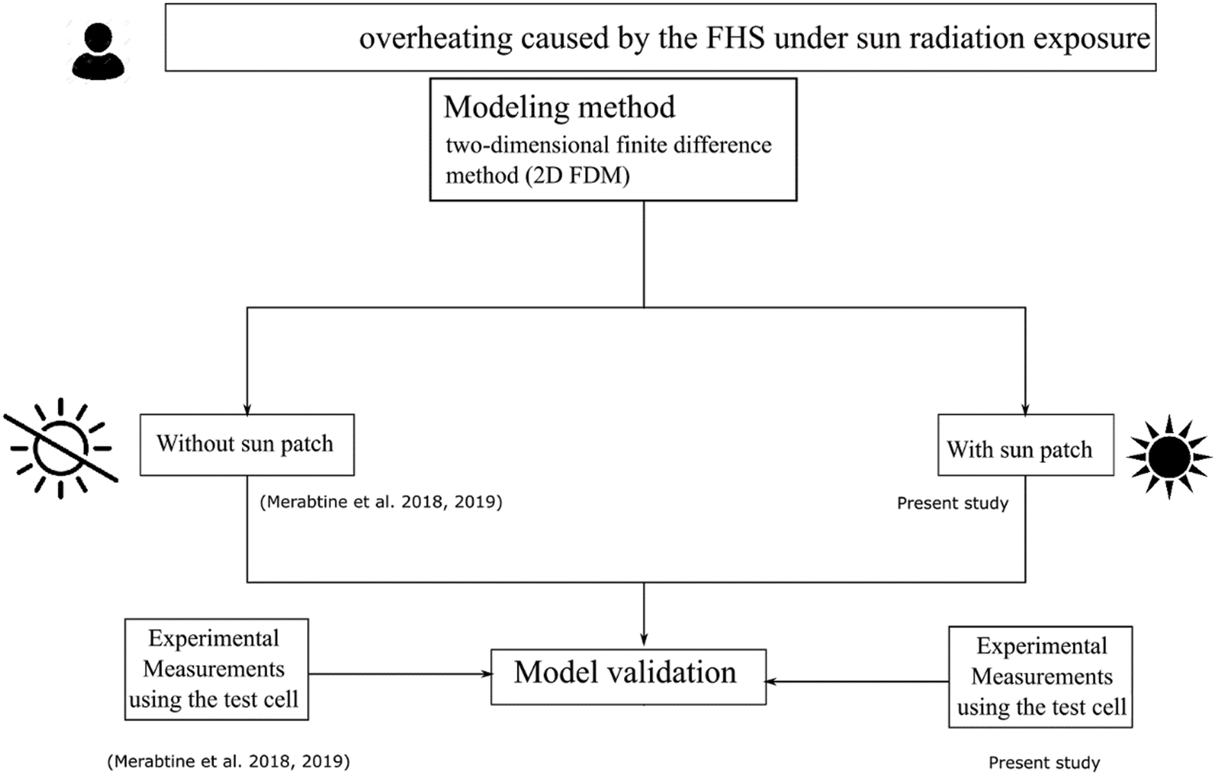
Figure 1: Flowchart of the adopted methodology
The performed measurements were carried out within a fully monitored and controlled bi-climatic chamber having well-insulated walls. Fig. 2 shows the test cell consisting of two adjacent rooms with a surface area of 5.5 m² each. The floor-to-ceiling height is 2.1 m. The heating of the left room is ensured by one or both of the following heating systems: a heated radiant slab, hydraulic radiators, and VAV system (Variable Air Volume). The cooled right room is supplied by a cooling system. Both climatic chambers are equipped with a mechanical ventilation system to control the indoor air quality by permanently ensuring fresh air supply. The heated room experimentally simulates the indoor environment in heating seasons. In contrast, the cooled room simulates the outdoor climatic conditions in which relative humidity (RH) and temperature are controlled. Further details about the thermophysical properties of the heated slab are indicated in Merabtine et al. [11].
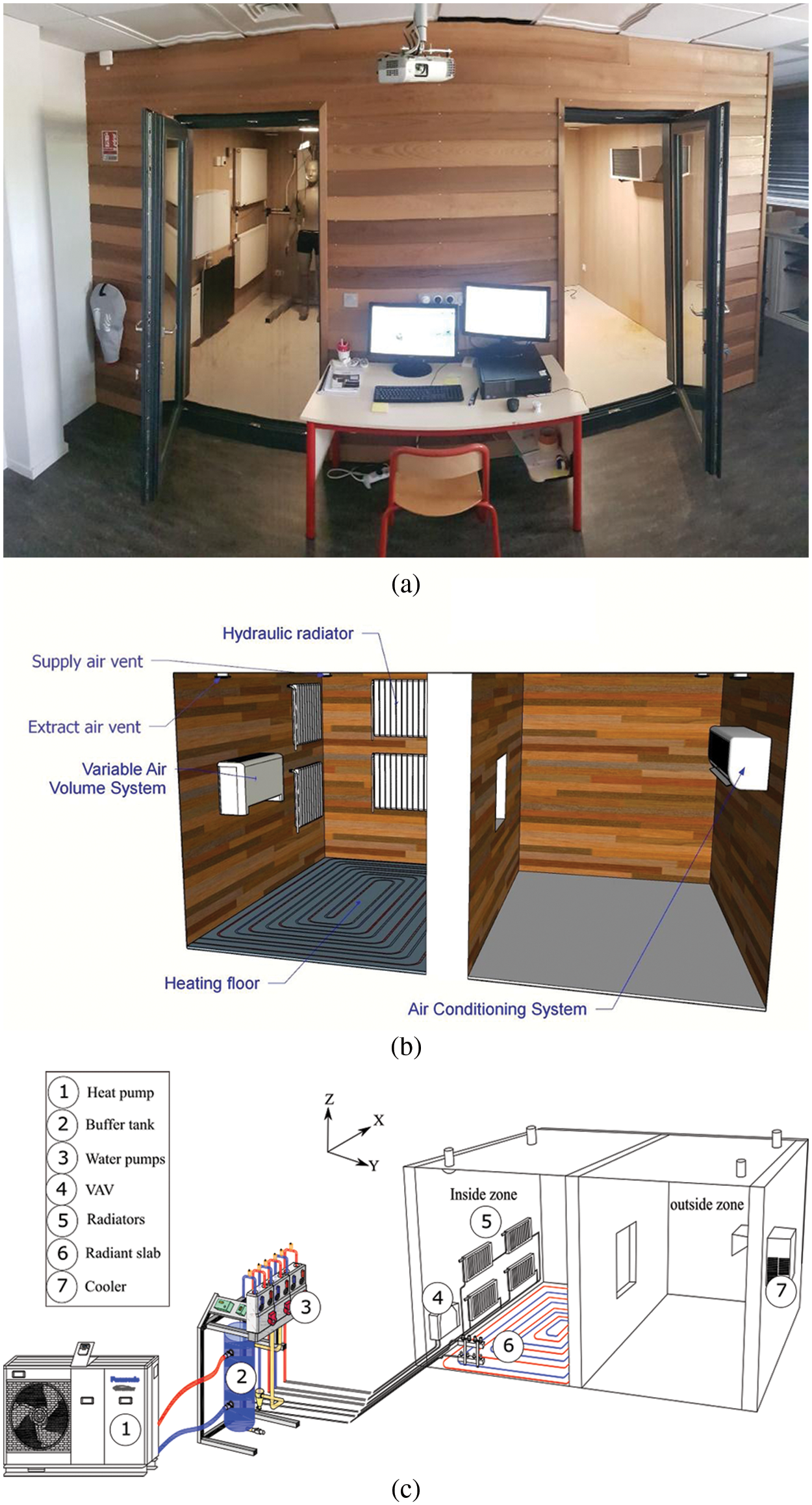
Figure 2: Full-scale bi-climatic chamber (a) outside view; (b) inside view; (c) overview of the HVAC systems
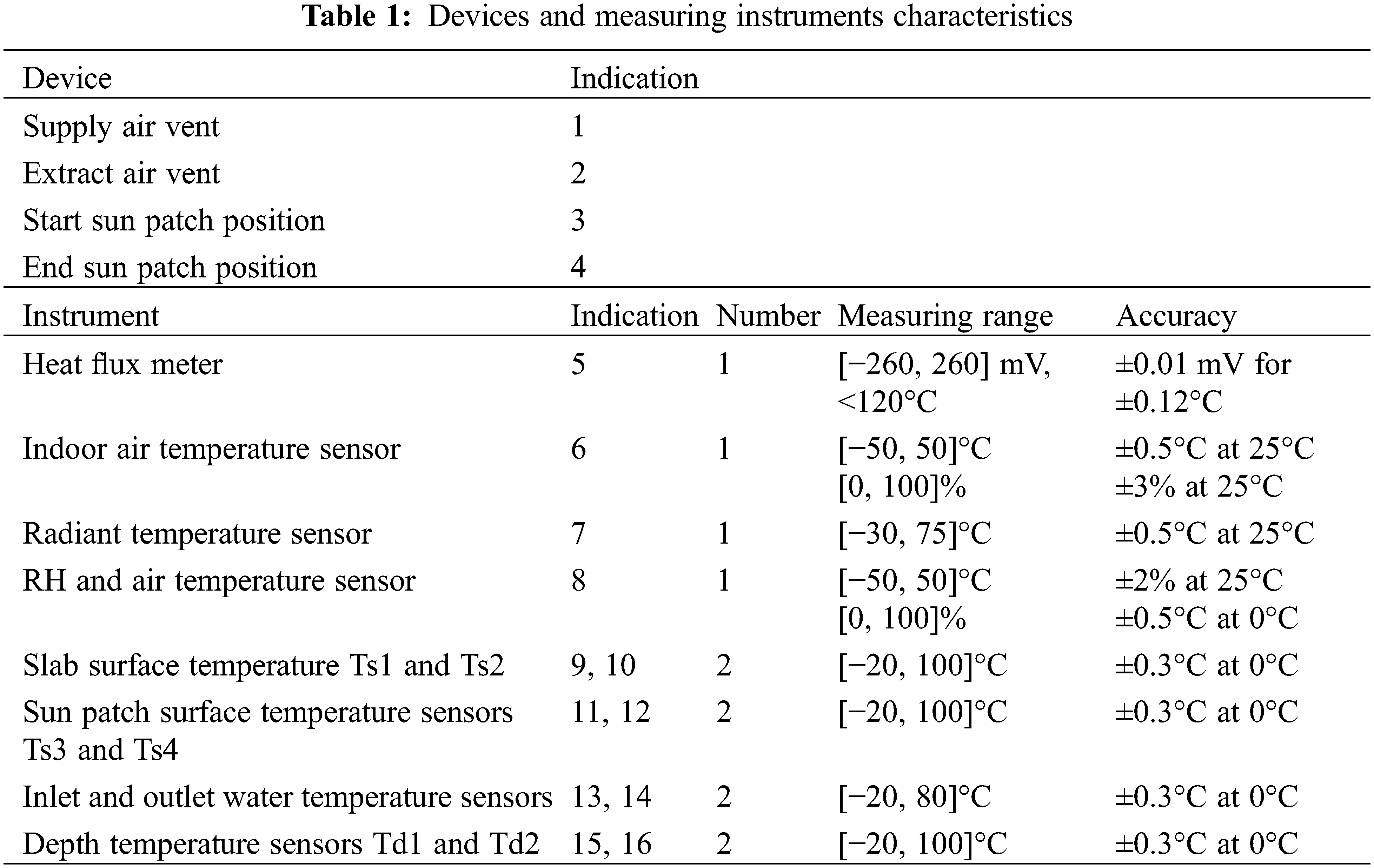
To allow post-treatment, the test cell was monitored with various types of sensors including heat flux meters; RH sensors as well as different sensors that monitor respectively the air temperature and the surface temperature that is directly enlightened by the sunbeams (i.e., the so-called the “sun patch”), the inlet and outlet water temperatures; and the depth temperature inside the slab. The recorded data are collected each minute thanks to the acquisition system. Table 1 depicts the main characteristics of the devices and measurement instruments.
Measurements were performed in real conditions. Ensured by the refreshing system, the cooling of the right room was established by maintaining the indoor temperature at 15°C while the FHS maintained the left room at 23°C. The radiant slab receives the hot water supplied by the heat pump at a maximum of 35°C. A three-way valve that mixes, if necessary, the supplied water with the returned one to inject the supplied water to a value in such a way that the indoor air temperature remains compliant with the desired value. In addition, we placed on the water loop a thermostatic valve located in the heated room. In this way, the supplied water flow rate was controlled with regard to the set point. Besides, a permanent air flow rate extracted from the right room set at 10 m3/h is supplied to the left heated space.
An electric resistance heating film experimentally represented the direct solar radiation exposure on the heated slab surface. Since the experimental set is situated in the French city of Troyes, where the pic of solar radiation in the winter season is 700 W/m², the varied electric heater power was chosen to attain this value as a maximum of the generated heat flux rate. Indeed, we used data from the weather station of Troyes-Barberey. This same value was used by Athienitis et al. [12] in their studies to simulate the maximum horizontal solar radiation on the heated slab.
To monitor the heat flux emitted by the heated slab then, a flux meter was positioned under the electric heater to quantify the conduction heat flux inside the heated slab. As depicted in Fig. 3, the direct solar radiation move was set in the way that the electric heater is set on a position and then linearly translated following three time-steps by a distance of 20 cm every 1.5 h with a total sun exposure duration of six hours. Two sensors were used to monitor the electric heating film’s local surface temperatures and moved with the heating film. The location of the sensors used in the experimental procedure is shown in Fig. 2. The collected data were recorded at a one-minute frequency.
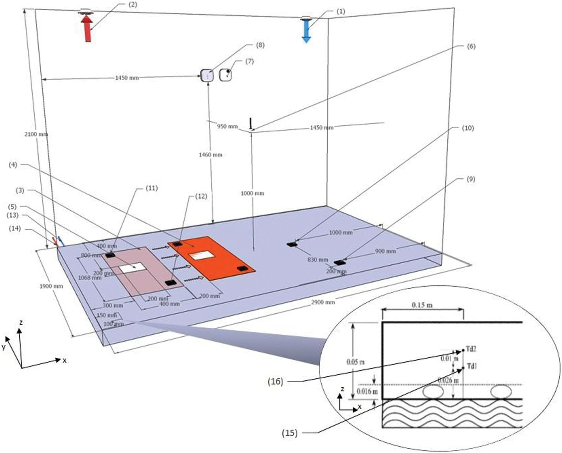
Figure 3: Experimental setup and sensor locations. (1) and (2) air vents; (3) beginning sun patch location (4) end sun patch localization.; (5) flux sensor; (6) indoor air temperature; (7) radiant temperature; (8) RH and indoor air temperature sensor (9–12) surface temperature sensors; (13) inlet water temperature (14) outlet water temperature (15) and (16) in-depth slab temperature sensors
To make easier the numerical modeling, the real configuration of the radiant heated slab’s real configuration is arranged to establish a 2D way modeling by assuming a heated floor with a straight line pipe. Hence, the heat flux vector is in the normal direction related to the slab surface. In this 2D model, x-axis represents the horizontal direction. In our former studies [10,11], we demonstrated that this assumption may be acceptable when the distance between piped is relatively small to diffuse heat in two main directions.
A central difference explicit scheme is adopted for discretization purposes. The first time and the second space derivatives are discretized following this scheme for the internal nodes. A local energy balance was used for the boundary nodes.
The heat transfer equation allowing to calculate Tc (x, z, t) the temperature inside the concrete slab is expressed as:
The fluid temperature
Eqs. (1) and (2) have the following boundary conditions:
On its lower surface the slab exchanges heat with the heating water, hence the boundary condition at this level is:
Since the heating slab exchanges heat at its upper surface by convection and by radiation, the following boundary condition is considered:
where
In order to calibrate the numerical model based on Finite Difference Method (FDM), surface temperatures of the radiant slab (Fig. 4), the average surface temperature, in-depth temperatures, and air temperature of the heated room are assessed numerically and experimentally. The sunbeam equivalent heating is applied at 21 h after the monitoring starts.
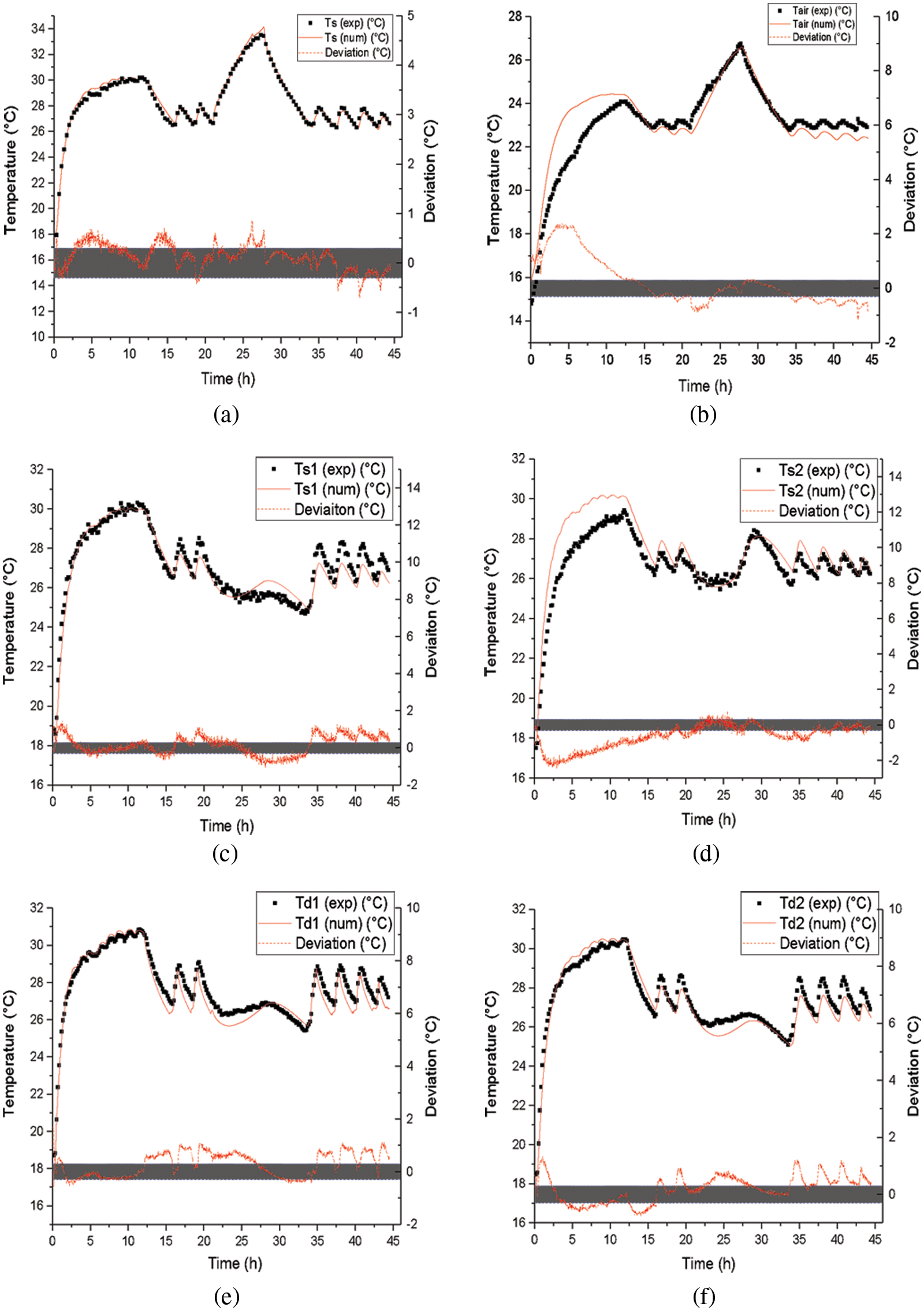
Figure 4: Time-dependent temperatures profiles of (a) the average surface temperature (b) the indoor air temperature (c) and (d) local surface temperature averaged measured on the surface, (e) and (f) in-depth slab temperature
Fig. 4a illustrates the good agreement between measurement data and numerical simulations. In fact, the identified difference remains in the range of ± 0.3°C (grey band). One could conclude that the model is accurate enough to estimate the surface temperature response.
In Fig. 4b, we can notice that for the indoor air temperature, an absolute error of 2.4°C is observed at the first heating step since the thermal inertia of the building envelope has roughly been taken into consideration in the numerical model. Once the steady state is reached, both measured and simulated results are similar for all of the heating periods.
Figs. 4c and 4d present the heated slab’s measured and simulated surface temperatures. Good accordance is observed between both profiles. The measured surface temperature Ts1 is a little bit higher than that recorded by the sensor Ts2. Indeed, to represent the actual heated slab surface temperature, the sensor Ts1 was positioned instinctively on the top surface of the slab above the inlet pipe, and Ts2 was localized in the center of the top surface of the slab, which is the less heated zone of the FHS. Regarding the numerical simulations, Ts1 and Ts2 are similar since the model equivalence considers only one straight inlet tube.
Moreover, it is noticed that before the activation of sunbeam equivalent heating, the temperature Ts1 shows a small difference with Ts2 (less than 1°C) and the temperature profiles have similar trends. Also, one may notice that the averaged surface temperature encompasses a physical meaning and permits the assessment of the radiant heat slab thermal performance (Fig. 4a).
Besides, the overheating due to the sunspot radiation stands near (i.e., at the vertical of) the hot water pipe (Fig. 4c). The sunbeam heating less impacts the non-exposed parts of the heating floor (Fig. 4d).
In the presented investigation, experiments carried out in the monitored bi-climatic chamber demonstrated that overheating duration due to the solar radiation gain reaches 8.5 h in our case study including the time after the sun patch disappears. The indoor air temperature records 26°C, while the slab temperature exceeds the upper limit of 29°C recommended by the standards. Beji et al. [2] found similar results.
The 2D developed finite difference model provides data that shows a good fit with the measurements, allowing the numerical model.
The present study’s findings can be generalized to all occupied highly glazed buildings suffering from overheating problems in mid-season. The considered FHS in our study is widely used, and a PID-based controlling system is nowadays commonly adopted.
The findings may be different for the a centralized controlling system for high-space buildings with many rooms/offices, and differently oriented and occupied spaces. In fact, complex thermal and aeraulic interactions may occur in the building between different heated spaces depending on the building height, glazed surface ratios, and orientations.
The case of “meeting rooms” with a high occupation rate compared to other office rooms still needs special attention. For such a situation, a decentralized control system has to be considered as a useful alternative solution to a centralized system. In fact, a centralized PID-based control system, even a hybrid floor heating cooling system, is not appropriate for such a case.
Integrating thermal comfort in the design avoids the need for an advanced control strategy, which could require additional device installations to keep continuous monitoring of the indoor environment, thus leading to additional installation and operation costs.
Acknowledgement: The following institutions and authorities are thanked for their precious contribution that permits this research work: for their technical support Météo France of Barberey-Saint-Sulpice; for their financial support Troyes Champagne Métropole, EPF Foundation European Regional Development Fund, and Grand-Est Region.
Funding Statement: The authors received no specific funding for this study.
Conflicts of Interest: The authors declare that they have no conflicts of interest to report regarding the present study.
References
1. Rhee, K. N., Olesen, B. W., Kim, K. W. (2017). Ten questions about radiant heating and cooling systems. Building and Environment, 112, 367–381. DOI 10.1016/j.buildenv.2016.11.030. [Google Scholar] [CrossRef]
2. Beji, C., Merabtine, A., Mokraoui, S., Kheiri, A., Kauffmann, J. et al. (2020). Experimental study on the effects of direct sun radiation on the dynamic thermal behavior of a floor-heating system. Solar Energy, 204, 1–12. DOI 10.1016/j.solener.2020.04.055. [Google Scholar] [CrossRef]
3. Bastien, D., Dermardiros, V., Athienitis, A. K. (2015). Development of a new control strategy for improving the operation of multiple shades in a solarium. Solar Energy, 122, 277–292. DOI 10.1016/j.solener.2015.08.020. [Google Scholar] [CrossRef]
4. Odyjas, A., Górka, A. (2013). Simulations of floor cooling system capacity. Applied Thermal Engineering, 51(1–2), 84–90. DOI 10.1016/j.applthermaleng.2012.08.029. [Google Scholar] [CrossRef]
5. Shin, M. S., Rhee, K. N., Ryu, S. R., Yeo, M. S., Kim, K. W. (2015). Design of radiant floor heating panel in view of floor surface temperatures. Building and Environment, 92, 559–577. DOI 10.1016/j.buildenv.2015.05.006. [Google Scholar] [CrossRef]
6. de Almeida Rocha, A. P., Rodler, A., Oliveira, R. C., Virgone, J., Mendes, N. (2019). A pixel counting technique for sun patch assessment within building enclosures. Solar Energy, 184, 173–186. DOI 10.1016/j.solener.2019.03.081. [Google Scholar] [CrossRef]
7. Rodler, A., Virgone, J., Roux, J. J. (2017). Adapted time step to the weather fluctuation on a three dimensional thermal transient numerical model with sun patch: Application to a low energy cell. Energy and Buildings, 155, 238–248. DOI 10.1016/j.enbuild.2017.09.027. [Google Scholar] [CrossRef]
8. Benzaama, M. H., Lachi, M., Maalouf, C., Mokhtari, A. M., Polidori, G. et al. (2016). Study of the effect of sun patch on the transient thermal behaviour of a heating floor in Algeria. Energy and Buildings, 133, 257–270. DOI 10.1016/j.enbuild.2016.09.066. [Google Scholar] [CrossRef]
9. Li, T., Merabtine, A., Lachi, M., Martaj, N., Bennacer, R. (2021). Experimental study on the thermal comfort in the room equipped with a radiant floor heating system exposed to direct solar radiation. Energy, 230, 120800. DOI 10.1016/j.energy.2021.120800. [Google Scholar] [CrossRef]
10. Merabtine, A., Mokraoui, S., Kheiri, A., Dars, A., Hawila, A. A. W. (2018). Experimental and multidimensional numerical analysis of the thermal behavior of an anhydrite radiant slab floor heating system: A multi-objective sensitivity study. Energy and Buildings, 174, 619–634. DOI 10.1016/j.enbuild.2018.06.062. [Google Scholar] [CrossRef]
11. Merabtine, A., Kheiri, A., Mokraoui, S., Belmerabet, A. (2019). Semi-analytical model for thermal response of anhydrite radiant slab. Building and Environment, 153, 253–266. DOI 10.1016/j.buildenv.2019.02.030. [Google Scholar] [CrossRef]
12. Athienitis, A. K. (1997). Investigation of thermal performance of a passive solar building with floor radiant heating. Solar Energy, 61(5), 337–345. DOI 10.1016/S0038-092X(97)00077-7. [Google Scholar] [CrossRef]
Cite This Article
 Copyright © 2023 The Author(s). Published by Tech Science Press.
This work is licensed under a Creative Commons Attribution 4.0 International License , which permits unrestricted use, distribution, and reproduction in any medium, provided the original work is properly cited.
 Downloads
 Citation Tools