
 Submit a Paper
 Propose a Special lssue
 Open Access
ARTICLE

Theoretical and Experimental Analysis of Heat Transfer and Condensation in Micro-Ribbed Tubes
1
Xinxiang University, Xinxiang, 453000, China
2
Department of Architecture, Tohoku Institute of Technology, Sendai, 982-8577, Japan
* Corresponding Author: Daoming Shen. Email:
(This article belongs to the Special Issue: Computational Mechanics and Fluid Dynamics in Intelligent Manufacturing and Material Processing)
Fluid Dynamics & Materials Processing 2023, 19(6), 1411-1424. https://doi.org/10.32604/fdmp.2023.024924
Received 14 June 2022; Accepted 13 September 2022; Issue published 30 January 2023
 View Full Text
 Download PDF
Abstract
The thermal transmission coefficient for a micro-ribbed tube has been determined using theoretical relationships and the outcomes of such calculations have been compared with experiments conducted using a R1234yf refrigerant undergoing condensation. In particular four theoretical single-phase flow and three multi-phase flow models have been used in this regard. The experimental results show that: the Oliver et al. criterion equation overestimates the experimental results as its accuracy is significantly affected by the specific conditions realized inside micro-fin tubes; the Miyara et al. criterion equation prediction error is less than 15%; the Cavallini et al. approach gives the highest prediction accuracy; the Goto et al. model overestimates the test data. Such results are critically discussed and some indications for the improvement of such models are provided.Keywords
The most effective approach to provide the key to the energy problem in China is to enhance the energy utilization rate and save energy [1,2]. Most of the energy utilization has been realized by heat energy and various heat-exchange facility, and enhanced conduction of heat can improve the thermal performance of conduction of heat equipment, to reduce the temperature difference of conduction of heat and cut down the power dissipation of pumps, so boosted thermal transmission plays a key role in energy saving and improving energy utilization.
Although diverse enhanced pipes have been widely employed in the field of refrigeration and air conditioning, the heat exchange components, such as condenser and evaporator, are still the largest energy loss components in the refrigeration system. Therefore, the research on the development of efficient heat-exchange facilities is still the focus of the majority of scholars and has made gratifying achievements.
On account of the CO2 condensation conduction of heat experiment in the supercritical zone, Tao et al. [3] and Zhou [4] compared and analyzed the prediction effect of the conduction of heat dimensionless criterion equation. In order to obtain the conduction of heat characteristics under different flow patterns, Chen et al. [5,6] ran R134a flow condensation experiments in two different kinds of micro-finned tubes based on the test data, not only the boundary of annular flow and stratified flow had been redivided, but also the relational approach of annular flow conduction of heat had been regressed, so that it could fully predict the conduction of heat ratio under the corresponding working conditions with high accuracy.
In addition, according to the pool boiling conduction of heat experiment, Liu et al. [7] fitted a segmented conduction of heat relational approach for the conduction of heat performance under different heat flux conditions in the pool boiling conduction of heat process, and the new fitted relational approach showed a better prediction effect on the conduction of heat effect in the pipe.
Compared with the research in China, the experimental and theoretical analysis of condensation conduction of heat by scholars from other countries is more comprehensive. Tokhtarov et al. [8] reported the results of several experiments performed on a two-phase current in an open channel. The results confirmed the complexity of the two-phase current distribution phenomenon and the difficulty of how the converters were distributed in a multi-channel channel system; Mahvi et al. [9] investigated how heat is transferred between the converters and how the exchangers are distributed in the open channel during the two phases. From one point of view, the studies performed on pipes can be classified into two categories of experiments performed on large-scale and small-scale pipes. Esposito et al. [10] investigated the effect of flow maldistribution in cross-flow heat exchangers. In recent years, the use of compact heat exchangers for single and two-phase applications has increased in the process industry [11].
Based on Cavallini et al. [12], Shah [13], Jung et al. [14], Thome et al. [15], Kedzierski et al. [16] and Tang et al. [17], which are suitable for the condensation conduction of heat in the pipe with internal thread, the dimensionless criterion equation for prediction of condensation conduction of heat with internal threads have been developed. In addition, with the wide application of the herringbone tubes, the corresponding theoretical calculation model also appeared [18,19]. By concentrating on the combined effect of convection current for thermal transmission and entropy production analysis on combustion synthesis solution, Krishnan et al. [18] derived magnesia (17 nm) nanoparticles scattered in glycol-water and ethylene (50:50) traversing a micro-ribbed pipe heat-exchanging unit. Kedzierski et al. [19] presented fanning grating determinant measurements in a micro-ribbed pipe for R134a, and two probable low greenhouse effect potential refrigerants R1234yf and R450A took the place of R134a, made further efforts to develop thermal conductivity of local convection current boiling.
In summary, although there are more than a few experimental and theoretical studies on heat interchange characteristics in thermal transmission tubes, most of the theoretical models were based on the old refrigerants, and the prediction accuracy of the new refrigerants is not much analyzed by the relevant theoretical models. For the condensation conduction of heat in the micro-ribbed pipe, the physical properties of refrigerant, the structure of the micro-ribbed pipe, and the experimental conditions will be provided with a significant standing on the conduction of heat characteristics in the tube. As a result, the use of many existing criterion equations for condensation conduction of heat in the micro fin tube is extremely limited, and there is almost no universal criterion equation that can realize the whole condensation conduction of the heat process. Therefore, based on the R1234yf condensation conduction of heat experiment in the internal thread tube, the commonly used heat conduction criterion equation has to have its practicability checked in this paper. A more reasonable criterion equation for evaluating single-phase and multiphase flow is given. The check results not only provide guidance for the future research and development of an efficient heat exchanger, but they also can provide direction for improving the relational approach. Furthermore, the results can provide further theoretical bases and practical support for the design of a proper heat exchanger.
As manifested in Fig. 1, the diphasic refrigerant stored in the liquid reservoir flows to the preheating section by mean of the mass rate-of-flow meter driven by the refrigerant pump. In the preheating section, the accurate control of the refrigerant dryness at the inlet of the test section is realized by transforming the electric heating voltage and current, the refrigerant exchanges heat with the chilled water in the test section to complete the condensation experiment, and the refrigerant is throttled and depressurized by the electronic expansion valve flows into the condensation section for supercooling treatment. Finally, it flows into the reservoir for the next cycle.
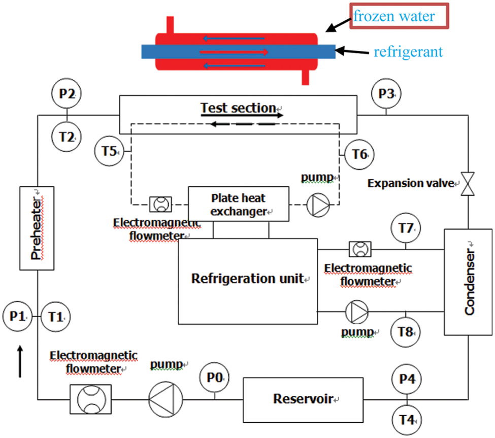
Figure 1: Diagram of the testing device
The temperature of the refrigerant and cooling water in the PT100 platinum resistance measuring system with an accuracy of 0.1oC is selected; the pressure of refrigerant in the system is setting-out by using the Guangtong AST4000 pressure sensor with an accuracy of 0.5%; KLB-CMFI Coriolis mass fluid meter is employed to determine the refrigerant circulation flow, its measurement accuracy is 0.2%, and the measurement range is 0.12 m3/h–450 m3/h.
In the experiment, the programmable logic controller (PLC) transmits the system’s temperature, pressure, flow, and other signals to the configuration software to realize the data acquisition of the upper computer and then to realize the processing of the experimental data.
When running the R1234yf flow condensation conduction of heat experiment in the pipe, the experimental conditions are set as bellow:
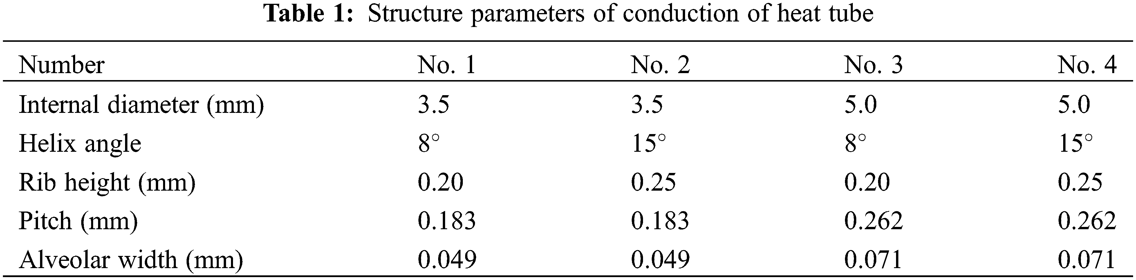
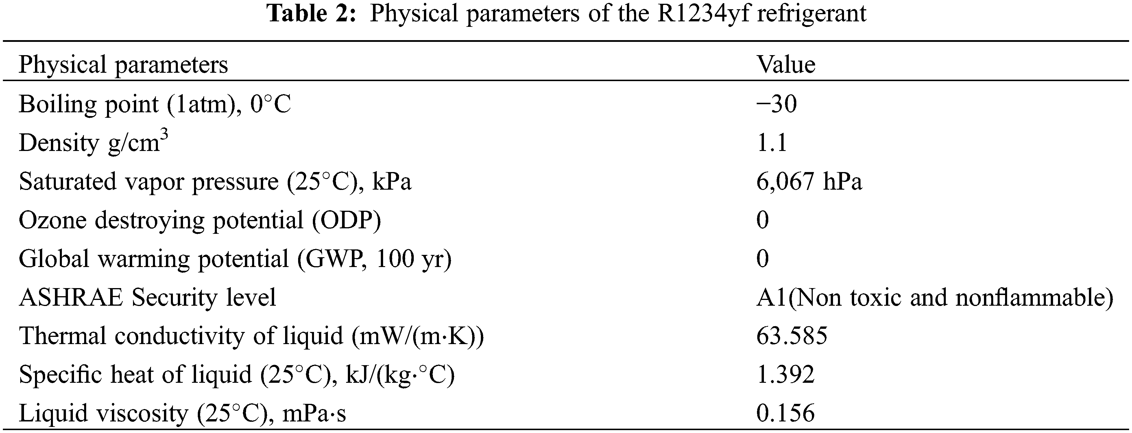
The mass flow rate range of refrigerant is 500–1000 kg/(m2⋅s); the condensation temperature is 40oC, 43oC, 45oC; the dryness of the refrigerant at the outlet and inlet of the test pipe is 0.8–0.9 and 0.2–0.3, respectively. Four types of micro rib tubes are selected as the test tubes, with the tip angle of 40o, the number of ribs of 60, and the length of heat exchange of 2500 mm. See Table 1 for other specific structural parameters. Physical parameters of the R1234yf refrigerant are shown in Table 2.
3 Experimental Data Processing
In the condensation experiment, the dryness values of the refrigerants at the outlet (xout) and at the intlet (xin) of the micro-ribbed tube are controlled by the electric heating quantity Qp and the heat absorption quantity Qw in the preheating section, respectively, in addition, the arithmetic mean values of xin and xout are selected as the calculation standard of the refrigerant dryness in the micro rib tube, that is:
Dryness value of refrigerant at the inlet of micro rib tube xin:
where: U/I is the electric heating voltage and current in the preheating section, V/A; hs is the saturated liquid enthalpy of the refrigerant under the specific pressure, kJ/kg; h1 is the refrigerant enthalpy in the entrance of the preheating segment, kJ/kg; hfg is the latent heat of the refrigerant under the specific pressure, kJ/kg; mr is the refrigerant mass flow, kg/s.
Heat absorption of chilled water Qw:
where: Cp is the specific heat capacity at a constant pressure of chilled water, J/(kg⋅oC); mw is the circulating flow of chilled water, kg/s; T5/T6 is the temperature of chilled water at the exit and entrance of test segment, °C.
The change value Δx of the refrigerant dryness in the micro-ribbed tube is:
The thermal resistance separation method is taken to calculate the conduction of heat ratio in the tube. The conduction of heat resistance between the refrigerant and the chilled water mainly includes the heat resistance on the chilled water side, the heat resistance on the refrigerant side as well as the heat resistance on the tube wall [20], that is:
Total thermal transmission coefficient of test section K:
In the formula, ΔT is the logarithmic mean temperature difference the refrigerant temperature in the outlet and entrance of the micro-ribbed tube, °C; in the calculation, Ts is calculated according to the saturation temperature, °C.
The coefficient of conduction of heat of the chilled water in the annular tube is calculated by the relational approach of Gnielinski et al. [21].
thermal transmission coefficient of refrigerant in pipe of combined formulas (5)–(7):
4 Verification of the Experimental Platform
In order to guarantee the accuracy of the measured arguments, before the diphasic conduction of heat experiment, R1234yf single-phase flow condensation conduction of heat experiment was carried out in a smooth tube with an internal diameter of 3.5 mm. The specific working conditions are: mass flow rate is 400–1100 kg/(m2⋅s), the refrigerant temperature at the outlet and inlet of the heat exchange tube is 30°C/50°C. Finally, the Nusselt number (Nu) experimental value is compared with Gnielinski’s calculated value [21]; the comparison results are as shown in Fig. 2: the experimental value of the Nusselt number(Nu) is highly consistent with the calculated value of the relational formula, with the maximum error is 6.30% and an average error of 3.29%. The results meet the requirements of experimental data measurement.
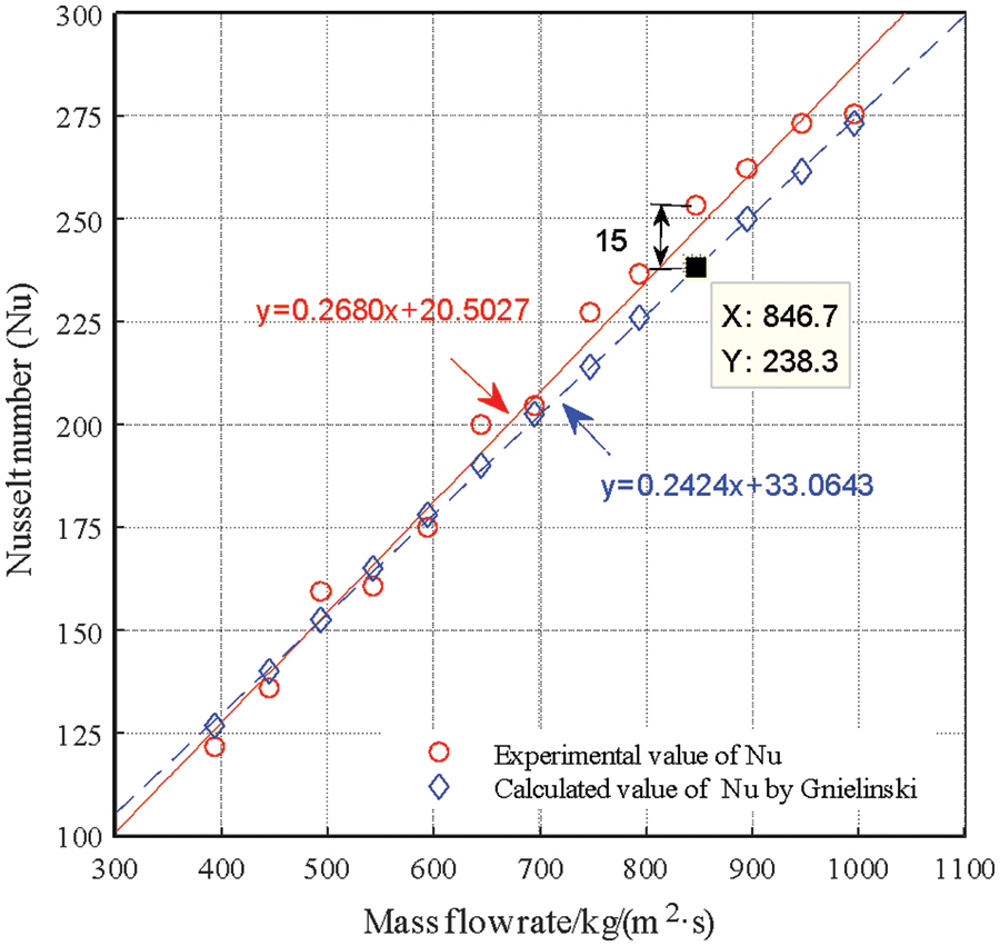
Figure 2: Comparison between the experimental value and single phase flow relational approach calculated value
5 Analysis of Experimental Data
The fitting mechanism of the relational approach of thermal transmission coefficient is mainly as follows: using similarity principle or dimensional analysis method, all influencing factors are summed up as dimensional criteria. Finally, the relationship between the calculation relational approach formula and dimensional criteria is determined by experiments.
According to the assumption of the relational approach to the conduction of heat mechanism of the fluid in the pipe, the relational approach of the thermal transmission coefficient can be divided into two categories: The single flow model as well as the multi-phase flow model. The single flow model assumes that the diphasic flow pattern in the tube is single flow pattern, which is not affected by the experimental conditions (similar to the homogeneous model in the pressure drop relational approach); The multiphase flow model calculates the conduction of heat in different regions of the tube.
According to the conduction of heat mechanism under different flow models, the conduction of heat effect in the tube under different flow patterns is fully considered (similar to the phase separation model in the pressure drop relational approach).
Under the experimental condition, when the mixing effect of diphasic flow in the pipe is imprecision, the single flow model’s prediction effect on the pipe’s thermal transmission coefficient is inaccurate. The comprehensive consideration of multiphase flow model on the conduction of heat mechanism in the pipe can realize the high-precision prediction of the thermal transmission coefficient in the pipe.
In this paper, four single-phase flow models, Cavallini et al. relational approach [22], Oliver et al. relational approach [23], Tang et al. relational approach [17], Kedzierski et al. relational approach [16], as well as three multiphase flow models, Koyama et al. relational approach [24], Miyara et al. relational approach [25] and Goto et al. relational approach [26], are put into use to predict the thermal transmission coefficient in the micro-ribbed tube, at the same time of comparing different relational approach prediction effects, the paper analyzes the relational approach prediction effects from the perspective of relational approach fitting mechanism.
5.1 Single Phase Flow Relational Approach Prediction Effect Analysis
Cavallini et al. relational approach [12] is an improvementof Cavallini-Zecchin’s relational approach [27], which can be used to predict the internal thermal transmission coefficient of the micro-ribbed tube’ Oliver et al. relational approach [23] is an improved relational approach of Cavallini et al. [12], which is mainly employed to predict the thermal transmission coefficient of stratified flow and annular flow in the micro fin tube. Four dimensionless variables, Reeq (equivalent Reynolds number), Bo (bond number), Fr (Froude numberand) and Rx (shape strengthening factor), are put into use to characterize the effects of experimental conditions, refrigerant physical properties and structural parameters of micro-ribbed tube on the conduction of heat characteristics in the tube:
In the formula, Reeq represents the turbulent effect of two-phase flow in the pipe under different mass flow; Bond number (Bo) and Froude number (Fr) indicate the comprehensive effect of shear force, gravity and surface tension on the conduction of heat in the tube, respectively; Rx indicates the augment results of two factors, the disturbance of helical angle of fins and the increase of conduction of heat area to the diphasic flow.
Cavallini et al. relational approach [12]:
Oliver et al. relational approach [23]:
The prediction effect of Oliver et al. relational approach [23] and Cavallini et al. relational approach [12] on the thermal transmission coefficient in the tube is shown in Fig. 3. It can be caught sight of from the figure that although Cavallini et al. relational approach [12] overestimates 94.3% of the value of the thermal transmission coefficient in the pipe, the prediction effect of the relational approach is perfected. The error range between the calculated value of the relational approach and the test value of the thermal transmission coefficient is −9.04%∼41.01%, and the average error of the two is 15.31%, as shown in Fig. 3a.
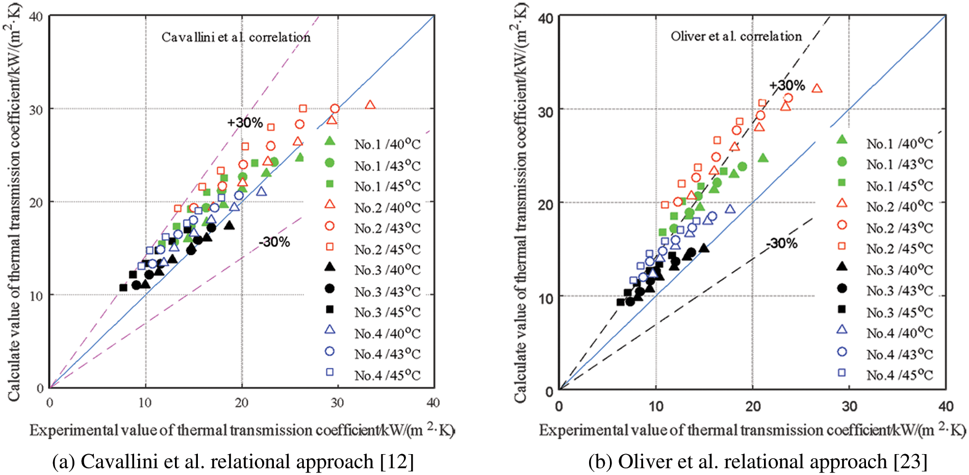
Figure 3: Comparison between the experimental value and single phase flow relational approach calculated value
Oliver et al. relational approach [23] overestimates all the thermal transmission coefficients in the tube, and the experimental conditions, structural parameters, and other variables will possess a significant position on the prediction accuracy of Oliver et al. relational approach [23]. Among them, Oliver et al. relational approach [23] have a relatively high prediction accuracy for the thermal transmission coefficients of No. 1 and No. 3 tubes; that is, with the increase of the spiral angle of the fins, the prediction error of Oliver et al. relational approach [23] gradually increases, and the error range between the calculated value of the relational approach and the experimental value of thermal transmission coefficient is 1.07%∼79.56%, with an average error of 35.12%, as shown in Fig. 3b.
Although Tang et al. relational approach [17] and Kedzierski et al. relational approach [16] are improved based on the relational approach of thermal transmission coefficients in different smooth tubes, both of them use the hydraulic diameter Dh to characterize the effect of rib structure parameters on the turbulence intensity of two-phase flow in the tube, and use the pressure ratio (Pr/Pc) to characterize the conduction of heat mechanism of diphasic flow in the main pipe [28].
Tang et al. relational approach [17]:
Kedzierski et al. relational approach [16]:
where: β1 = 0.235; β3 = 0.308; β4 = −1.16x2; β5 = −0.887x2; β6 = 2.708x.
In addition, Tang et al. [17] determined the coefficients a, C, d, and n, respectively, according to different structural parameters of heat exchange tubes. For the experimental heat exchange tubes in this paper, a = 210.19, C = 24, d = 0.48, n = 0.72. Kedzierski et al. relational approach [16] not only uses the dimensionless specific volume Sv to characterize the gas-liquid distribution of the diphasic flow in the pipe and the dimensionless index β to characterize the conduction of heat effect of the diphasic flow in the pipe under different dryness conditions.
With regard to the thermal transmission coefficient in the tube, the prediction effects of Tang et al. relational approach [17] and Kedzierski et al. relational approach [16] are shown in Fig. 4. It could be demonstrated from the figure that both of them have the same prediction effects on the thermal transmission coefficient in the tube, i.e., the prediction error of relational approach increases with the raising of mass flow, this is because: with the up-grading of mass flow rate, the conduction of heat enhancement effect caused by the turbulence of diphasic flow in the tube, the fin disturbance gradually replaces the conduction of heat enhancement effects, the acceleration of condensate discharge and the surface tension, that is, the hydraulic diameter Dh and Reynolds number Rel in the relational approach formula can not fully represent the turbulence enhancement effect caused by the turbulence of two-phase flow in the tube, the fin disturbance and the increase of mass flow rate. Therefore, the conduction of heat effect in the pipe is underestimated. In addition, the prediction accuracy of Kedzierski et al. relational approach [16] is greatly affected by the structure of the heat exchange tube and the prediction effect of Kedzierski et al. relational approach [16] on No. 3/4 micro-ribbed tube is significantly higher than that of No. 1/2 micro-ribbed tube. Through calculation and comparison, the error range between the calculated value of Tang et al. as well as Kedzierski et al. [16] and the test value of thermal transmission coefficient is −49.42%∼15.41% and −43.46%∼41.76%, respectively, and the mean error of the two is −20.95% and −7.75%, respectively.
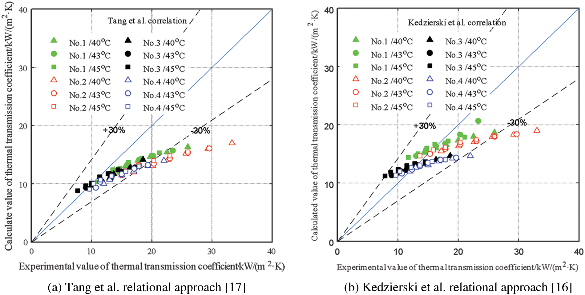
Figure 4: Comparison between the experimental value and single phase flow relational approach calculated value
5.2 Prediction Effect Analysis of Multiphase Flow Relational Approach
Multiphase flow relational approaches are mostly adopted to foretell the thermal transmission coefficient of two-phase flow in stratified flow and annular flow with the obvious gas-liquid distribution. It is assumed that the conduction of heat forms in the pipe mainly includes film condensation conduction of heat between gas-liquid surfaces and forced convection conduction of heat in the liquid film. Many scholars have analyzed the influence of structural parameters and experimental conditions on the turbulence of two-phase flow, and the influence of variables on the forced convection conduction of heat mechanism was developed.
Based on Eq. (17) and the experimental values of thermal transmission coefficient in different types of enhanced tubes, The Koyama et al. relational approach [24], Miyara et al. relational approach [25] and Goto et al. relational approach [26] are selected in this paper, all the expression form of forced convection Nusselt number NuF is determined. Among them, the Koyama et al. relational approach [24] is mainly applicable to the prediction of the thermal transmission coefficient in the internal screw pipe, while the Miyara et al. relational approach [25] is an improved relational approach of Koyama et al. relational approach [24], which is mainly according to the experimental values of the condensation thermal transmission coefficient of R22 and R410A two-phase flow in the herringbone tooth pipe to redetermine the expression of the coefficient ΦV.
Koyama et al. relational approach [24] forced convection Nusselt number NuF:
Miyara et al. relational approach [25] forced convection Nusselt number NuF:
Goto et al. [26] assumed that the coefficient ΦV is only a function of the parameter Xtt, and refits the expression of NuF according to the experimental values of two-phase flow condensation thermal transmission coefficient of R22 and R410A in the herringbone toothed tube with an external diameter of 8 mm and a mass flow range of 130–400 kg/(m2⋅s), namely:
Forced convection Nusselt number NuF:
The prediction effect of Koyama et al. relational approach, Miyara et al. relational approach [25] and Goto et al. relational approach [26] on the thermal transmission coefficient in the micro-ribbed tube are shown in Fig. 5, from the figures, it can be observed that Koyama et al. relational approach [24] can achieve high-precision prediction of the thermal transmission coefficient in the tube, but the structural parameters of the micro rib tube and the experimental conditions (such as condensation temperature) have a great influence on the calculation accuracy of the relational approach. The error range between the calculated value of Koyama et al. relational approach [24] and the experimental value of the thermal transmission coefficient is −20.21%∼53.86%, and the average error of the two is 12.97%, as shown in Fig. 5a.
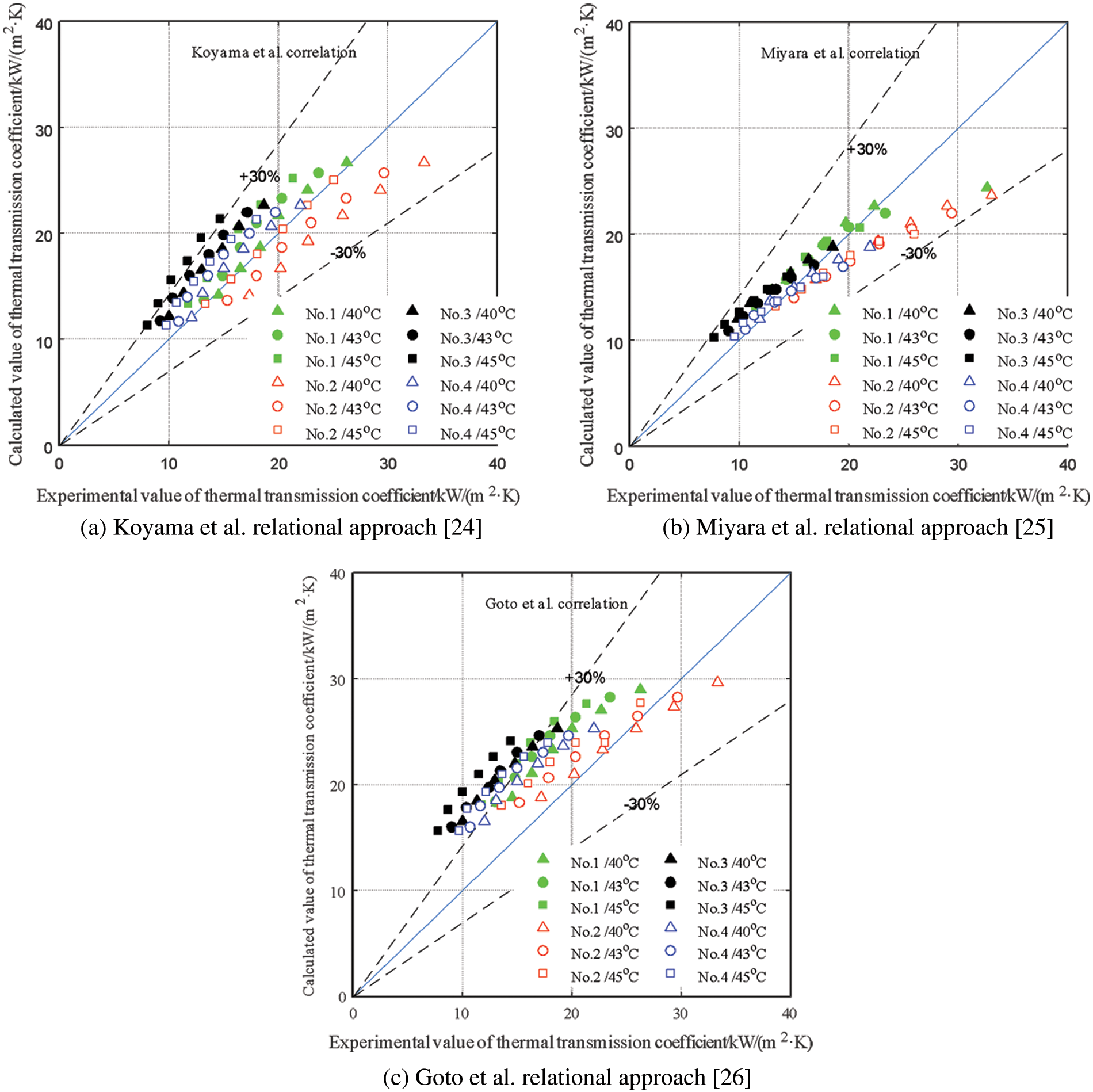
Figure 5: comparison between the experimental value and multiple phase flow relational approach calculated value
For the internal thermal transmission coefficient of internal thread pipe, the relational approach of Miyara et al. [25] shows a good prediction effect, which is inconsistent with the test results of Miyara et al. [25], the internal thermal transmission coefficient of internal thread pipe is smaller than that of herringbone tooth pipe. Due to the non-visualization of the heat exchange tube, it is still uncertain that the diphasic flow mechanisms in the herringbone pipe and the internal thread pipe are different, but the different flow mechanisms are to enhance the heat exchange effect by enhancing the diphasic flow turbulence in the tube. The enhancement action of the herringbone rib on the turbulence is obviously due to the spiral rib.
In this paper, the enhancement effect of mass flow and fins on the turbulence intensity of two-phase flow weakens the gap between the flow mechanisms caused by different fins, which makes the prediction effect of Miyara et al. relational approach [25] contrary to the experimental results. However, this does not mean that Miyara et al. relational approach [25] is also suitable for the prediction of thermal transmission coefficient in internal screw pipe. The error range between the calculated value of Miyara et al. relational approach [25] and the test value of thermal transmission coefficient is −26.98%∼30.95%, and the average error of the two is 0.64%, as shown in Fig. 5b.
Goto et al. relational approach [26] overestimates 94.6% of the thermal transmission coefficient in the tube, that is, the relational approach prediction results are consistent with the test data, and the relational approach prediction accuracy has a great influence on the structure characteristic parameter of the heat-exchange tube. Goto et al. relational approach [26] prediction accuracy increases with the augment of the radius of the heat exchange tube and the decrease of the spiral angle of the fins. The error range between Goto et al. relational approach [26] calculation results and the experimental results of the thermal transmission coefficient is −13.18%∼101.37%, the average of the two. The error is 37.84%, as shown in Fig. 5c.
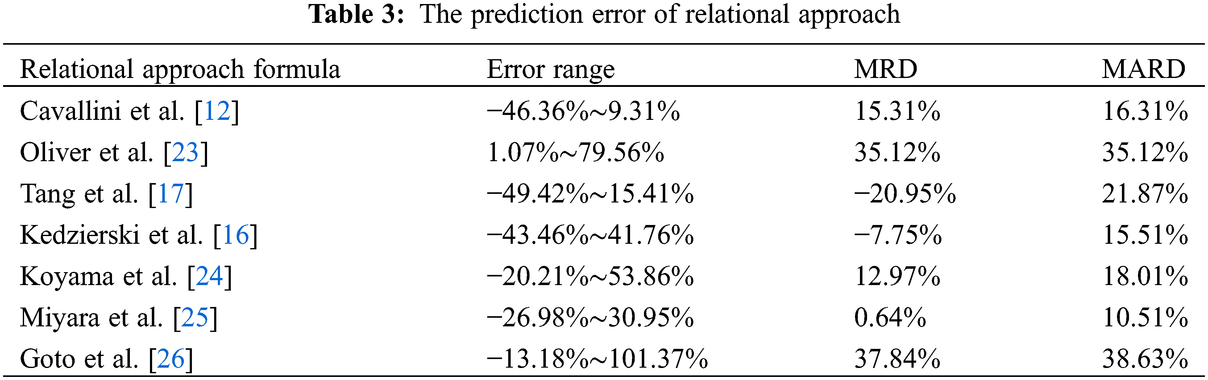
For the above relational approach, this paper selects the mean error (MRD) and mean absolute error (MAR) to evaluate the prediction effect of the relational approach. The specific prediction errors of each relational approach are listed in Table 3.
Based on the R1234yf flow condensation conduction of heat experiment in the internal thread tube, the prediction ability of the commonly used prediction relational approach of thermal transmission coefficient in the strengthened tube is checked, and the prediction accuracy is analyzed from the relational approach fitting mechanism. The main conclusions are as follows:
(1) For the single-phase flow relational approach, Cavallini et al. relational approach [12] showed significant advantages, with an average prediction error of 15.31%, while Oliver et al. relational approach [23] overestimate all experimental results. Oliver et al.’s relational approach’s [23] prediction accuracy is greatly affected by the structure characteristic parameter of micro-ribbed pipes and experimental conditions. In addition, the prediction error of Tang et al. relational approach [17] and Kedzierski et al. relational approach [16] increases with the improvement of mass flow rate, which could not achieve the higher precision prediction of thermal transmission coefficient in the pipe.
(2) The prediction effect of Tang et al. relational approach [17] and Kedzierski et al. relational approach [16] on the thermal transmission coefficient in the tube could be demonstrated from the figure that both of them have the same prediction effect on the thermal transmission coefficient in the tube.
(3) For the multi-phase flow relational approach, Koyama et al. relational approach [24] and Miyara et al. relational approach [25] showed better prediction results, with prediction errors of less than 20%; while Goto et al. relational approach [26] overestimates the test results, and the prediction results are completely consistent with the experimental comparison results.
(4) The prediction effect of Koyama et al. relational approach [24], Miyara et al. relational approach [25], and Goto et al. relational approach [26] on the thermal transmission coefficient in the micro-ribbed tube can be observed that Koyama et al. relational approach [24] can achieve high-precision prediction of the thermal transmission coefficient in the tube. Still, the structural parameters of the micro rib tube and the experimental conditions (such as condensation temperature) have a great influence on the calculation accuracy of the relational approach.
(5) Based on the R1234yf condensation conduction of heat experiment in the internal thread tube, this paper checks the practicability of the commonly used conduction of heat relational approach. The check results not only provide guidance for the research and development of efficient heat exchanger, but also provide direction for improving the relational approach. Furthermore, it can provide a theoretical basis and practical support for an improved heat exchanger design.
Funding Statement: This work was supported by the National Natural Science Foundation of China (No. 41877251) and Major Science and Technology Projects of Xinxiang City (No. 21ZD012).
Conflicts of Interest: The authors declare that they have no conflicts of interest to report regarding the present study.
References
1. Pham, Q. V., Choi, K. I., Oh, J. T., Cho, H. (2019). Flow condensing heat transfer of R410A, R22, and R32 inside a micro-fin tube. Experimental Heat Transfer, 32(2), 102–115. [Google Scholar]
2. Singh, S., Kukreja, R. (2019). An experimental investigation of flow patterns during condensation of HFC refrigerants in horizontal micro-fin tubes. International Journal of Air-Conditioning and Refrigeration, 27(1), 1–17. [Google Scholar]
3. Tao, Y., Wu, Z., Zhou, J. (2006). Comparisons of conduction of heat and pressure drop relational approachs for in-tube cooling of CO2 in supercri tical region. HV&AC, 36(3), 25–28. [Google Scholar]
4. Zhou, Z. (2015). Conduction of heat relational approachs for in-tube cooling of supercritical CO2. Refrigeration, 64(3), 45–49. [Google Scholar]
5. Chen, Q., Xin, M. (2002). Flow regimes and stratified-wave flow experimental relational approach of condensation conduction of heat in three-dimensional micro-fin tube. CIESC Journal, 53(7), 755–758. [Google Scholar]
6. Chen, Q., Cui, W., Xin, M. (2003). Flow patterns and the annular flow experimental relational approach of R134a condensation conduction of heat in three-dimensional microfin tube. Journal of Xi’an Jiaotong University, 34(11), 27–30. [Google Scholar]
7. Liu, S., Liu, J., Ning, J. (2013). Theoretical analysis on relational approach of CO2 pool boiling conduction of heat. Fluid Machinery, 9, 81–86. [Google Scholar]
8. Tokhtarov, Z., Perov, V., Borisov, V., Tikhomirov, E., Grunina, O. et al. (2022). Experimental investigation of two-phase flow maldistribution in plate heat exchangers. Fluid Dynamics & Materials Processing, 18(4), 1015–1024. DOI 10.32604/fdmp.2022.019534. [Google Scholar] [CrossRef]
9. Mahvi, A. J., Garimella, S. (2019). Two-phase flow distribution of saturated refrigerants in microchannel heat exchanger headers. International Journal of Refrigeration, 104, 84–94. DOI 10.1016/j.ijrefrig.2019.04.026. [Google Scholar] [CrossRef]
10. Esposito, A., Lappa, M., Pagliara, R., Spada, G. (2022). A mixed radiative-convective technique for the calibration of heat flux sensors in hypersonic flow. Fluid Dynamics & Materials Processing, 18(2), 189–203. DOI 10.32604/fdmp.2022.019605. [Google Scholar] [CrossRef]
11. Arslan, E., Koşan, M., Aktaş, M., Dolgun, E. C. (2020). Designing of a new type air-water cooled photovoltaic collector. Tehnicki Glasnik, 14(1), 41–45. DOI 10.31803/tg-20190227095246. [Google Scholar] [CrossRef]
12. Cavallini, A., Censi, G., Col, D. D., Doretti, L., Zilio, C. (2003). Condensation inside and outside smooth and enhanced tubes–A review of recent research. International Journal of Refrigeration, 26(4), 373–392. [Google Scholar]
13. Shah, M. M. (1979). A general relational approach for conduction of heat during film condensation inside pipes. International Journal of Heat & Mass Transfer, 22(4), 547–556. [Google Scholar]
14. Jung, D., Song, K. H., Cho, Y., Kim, S. J. (2003). Flow condensation heat transfer coefficients of pure refrigerants. International Journal of Refrigeration, 26(1), 4–11. [Google Scholar]
15. Thome, J. R., Hajal, J. E., Cavallini, A. (2003). Condensation in horizontal tubes, Part 2: New conduction of heat model based on flow regimes. International Journal of Heat & Mass Transfer, 46(18), 3365–3387. [Google Scholar]
16. Kedzierski, M. A., Goncalves, J. M. (1999). Horizontal convective condensation of alternative refrigerants within a micro-fin tube. Journal of Enhanced Conduction of Heat, 6(2), 161–178. [Google Scholar]
17. Tang, L., Ohadi, M. M., Johnson, A. T. (2000). Flow condensation in smooth and micro-fin tubes with HCFC-22, HFC-134a and HFC-410A refrigerants. Part I: Experimental results. Journal of Enhanced Conduction of Heat, 7(5), 289–310. [Google Scholar]
18. Krishnan, S., Suseel, J., Nagarajan, P. K. (2019). Convective thermal performance and entropy generation analysis on solution combustion synthesis derived magnesia nano-dispersion flow susceptible by a micro-fin tube. Experimental Thermal and Fluid Science, 101, 1–15. [Google Scholar]
19. Kedzierski, M. A., Kang, D. (2018). Horizontal convective boiling of R1234yf, R134a, and R450A within a micro-fin tube. International Journal of Refrigeration, 88, 538–551. [Google Scholar]
20. Tao, W., Kang, H. (1997). Turbulent conduction of heat measurement in air cooler tube sets using heat resistance separating method. HV&AC, 27(z1), 64–67. [Google Scholar]
21. Gnielinski, V. (1976). New equations for heat and mass transfer in turbulent pipe and channel flow. International Chemical Engineering, 16(2), 8–16. [Google Scholar]
22. Cavallini, A., Del Col, D., Doretti, L., Longo, G. A., Rossetto, L. (1999). A new computational procedure for conduction of heat and pressure drop during refrigerant condensation inside enhanced tubes. Journal of Enhanced Conduction of Heat, 6(6), 441–456. [Google Scholar]
23. Olivier, J. A., Liebenberg, L., Thome, J. R. (2007). Conduction of heat, pressure drop, and flow pattern recognition during condensation inside smooth, helical micro-fin, and herringbone tubes. International Journal of Refrigeration, 30(4), 609–623. DOI 10.1016/j.ijrefrig.2006.11.003. [Google Scholar] [CrossRef]
24. Koyama, S., Yu, J. (1998). Condensation conduction of heat of pure refrigerants in microfin tubes. British Journal of Haematology, 139(1), 281–288. [Google Scholar]
25. Miyara, A., Nonaka, K., Taniguchi, M. (2005). Condensation conduction of heat and flow pattern inside a herringbone-type micro-fin tube. International Journal of Refrigeration, 23(2), 141–152. DOI 10.1016/S0140-7007(99)00037-7. [Google Scholar] [CrossRef]
26. Goto, M., Inoue, N., Ishiwatari, N. (2003). Condensation and evaporation conduction of heat of R410A inside internally grooved horizontal tubes. International Journal of Refrigeration, 26(4), 410–416. DOI 10.1016/S0140-7007(02)00153-6. [Google Scholar] [CrossRef]
27. Cavallini, A., Zecchin, R. A. (1974). A dimensionless correlation for heat transfer in forced convection condensation. International Heat Transfer Conference Digital Library, vol. 3, pp. 157–165. Begel House Inc. [Google Scholar]
28. Shen, D., Gui, C., Liu, Y., Xia, J. (2019). Experimental and theoretical analysis of conduction of heat enhancement inside micro-fin tube. Cryogenics, 229(3), 1–7. [Google Scholar]
Cite This Article
 Copyright © 2023 The Author(s). Published by Tech Science Press.
This work is licensed under a Creative Commons Attribution 4.0 International License , which permits unrestricted use, distribution, and reproduction in any medium, provided the original work is properly cited.
 Downloads
 Citation Tools