
 Submit a Paper
 Propose a Special lssue
 Open Access
ARTICLE

CFD Analysis of Spiral Flow Fields in Proton Exchange Membrane Fuel Cells
College of Mechanical and Electrical Engineering, Shandong Jianzhu University, Jinan, 250101, China
* Corresponding Author: Fayi Yan. Email:
Fluid Dynamics & Materials Processing 2023, 19(6), 1425-1445. https://doi.org/10.32604/fdmp.2023.025282
Received 03 July 2022; Accepted 11 October 2022; Issue published 30 January 2023
 View Full Text
 Download PDF
Abstract
Proton exchange membrane fuel cells (PEMFCs) are largely used in various applications because of their pollution-free products and high energy conversion efficiency. In order to improve the related design, in the present work a new spiral flow field with a bypass is proposed. The reaction gas enters the flow field in the central path and diffuses in two directions through the flow channel and the bypass. The bypasses are arranged incrementally. The number of bypasses and the cross-section size of the bypasses are varied parametrically while a single-cell model of the PEMFC is used. The influence of the concentration of liquid water and oxygen in the cell on the performance of different flow fields is determined by means of Computational fluid dynamics (COMSOL Multiphysics software). Results show that when the bypass number is 48 and its cross-sectional area is 0.5 mm2, the cell exhibits the best performances.Graphic Abstract
Keywords
With the continuous progress of the times, the development and utilization of hydrogen energy have become an important breakthrough in dealing with the problem of energy shortage [1–6]. Proton exchange membrane fuel cells (PEMFCs) are advanced power supply device that requires air and hydrogen to be pumped through the cathode and the anode, respectively. Given that the only products are heat and water, the whereabouts of the subsequent products should not be a concern [7–12]. The power generation efficiency of PEMFCs is easily affected by the external environment and built-in parameters, such as the flow field layout [13–15].
Many types of flow fields have been developed and utilized. The actual output effect indicates the significant impact of the flow field layout [16–19]. Wang et al. [20] found that in different flow field layouts, the setting of the physical parameters of the gas diffusion layer will distinctly affect the mass transfer and water removal efficiency inside the battery. Kerkoub et al. [21] compared the three basic flow fields, grouped the flow channel and the width of the rib and found that the sinuous structure of the serpentine flow field has a large pressure drop in the mass transfer process and good water removal effect and output performance. Yin et al. [22] designed a cross-shaped wave channel that have a good heat dissipation and a high flow rate. Ramin et al. [23] designed and performed numerical analysis on a flow field plate with a trap-shaped channel. Their results show that two 8-mm trap channel structures have the best-combined effect in improving the power efficiency of the battery. This new flow field also has the advantages of low processing difficulty and production cost. Vazifeshenas et al. [24] conducted a numerical study on a composite flow field, including parallel and serpentine structures, and found that the new composite structure could achieve the effect of learning from each other and effectively avoid the “flooding” phenomenon under the premise of maintaining the output power. In addition to the simple flow field structure that has been applied in practice, the types of new flow fields are also very diverse. On the basis of the honeycomb shape, Zhang et al. [25] designed a new honeycomb flow field structure. Owing to the uniform embedding of the polygonal rib, the flow channel guiding effect leads to the highly uniform oxygen distribution of the new flow field. Similarly, bionic flow fields based on leaf and lung structures have broad development prospects. Compared with traditional structures, the output power of bionic flow fields has been significantly improved [26,27]. Juarez-Robles et al. [28] conducted a comparative analysis on the multi-channel concentric spiral flow field and found that the spiral flow field has the highest current density value and the best comprehensive effect when the number of channels is 4. In addition, Wang et al. [29] found that the multi-inlet flow field may achieve unexpected results in improving battery performance. After setting the inlet number, the flow rate, and the relative humidity as variable factors, the reasonable distribution of the rest of the parameters, except for the relative humidity, can further improve the output power.
In addition to changing the overall flow field structure, changing the specific flow field geometry parameters (e.g., the rib width ratio and the cross-section area) is also an important way of improving the output performance of PEMFCs. Meanwhile, the cathode and anode flow fields can be set to have different structural forms. This approach can achieve improved temperature distribution in some conditions [30,31]. Cai et al. [32] changed the cross-sectional area of the flow channel by adding an obstruction to the one-way parallel flow field. Simulation analysis shows that both the length and quantity of obstruction have a decisive effect on the concentration of the oxygen arriving at the chemical reaction site. Jang et al. [33] developed a five-path spiral flow field with a channel inlet larger than the channel outlet. The experiment revealed that the small-outlet design could improve the oxygen flow rate at the end of the flow field and enhance the mass transfer effect. Compared with the serpentine flow field, the limiting current density of the spiral flow field increased by 11.9%.
According to the literature, the polarization loss can be reduced, and the working efficiency of the cell can be improved by changing the overall layout and internal parameters of the flow field. In this paper, a new spiral flow field with bypass is designed. The addition of a bypass can not only change the diffusion mode of the oxygen but also significantly reduce the high-pressure drop caused by an extremely long flow channel, compensating for the deficiency of the traditional spiral flow field. To investigate the influence of the number of bypasses and the cross-section size of the bypass on the output efficiency of PEMFCs, several single-cell models of the new flow field were established and simulated by the CFD software COMSOL Multiphysics. The optimum numerical combination of bypass parameters was found by comparing various performance indicators, including oxygen and water.
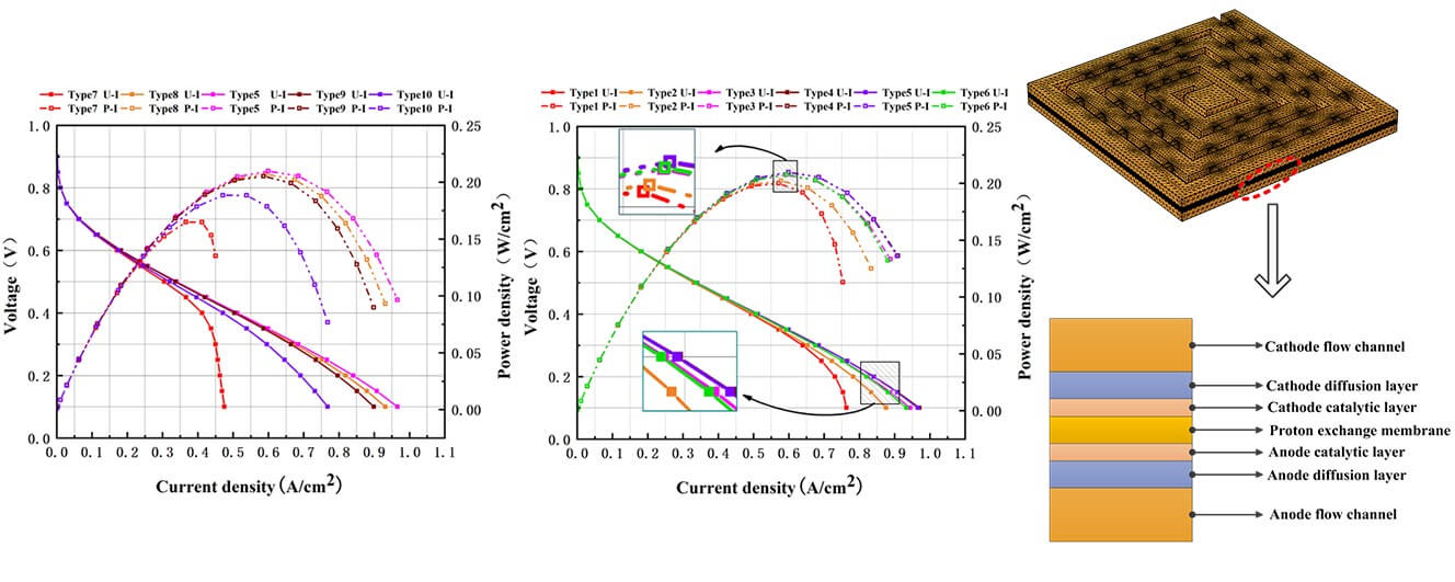
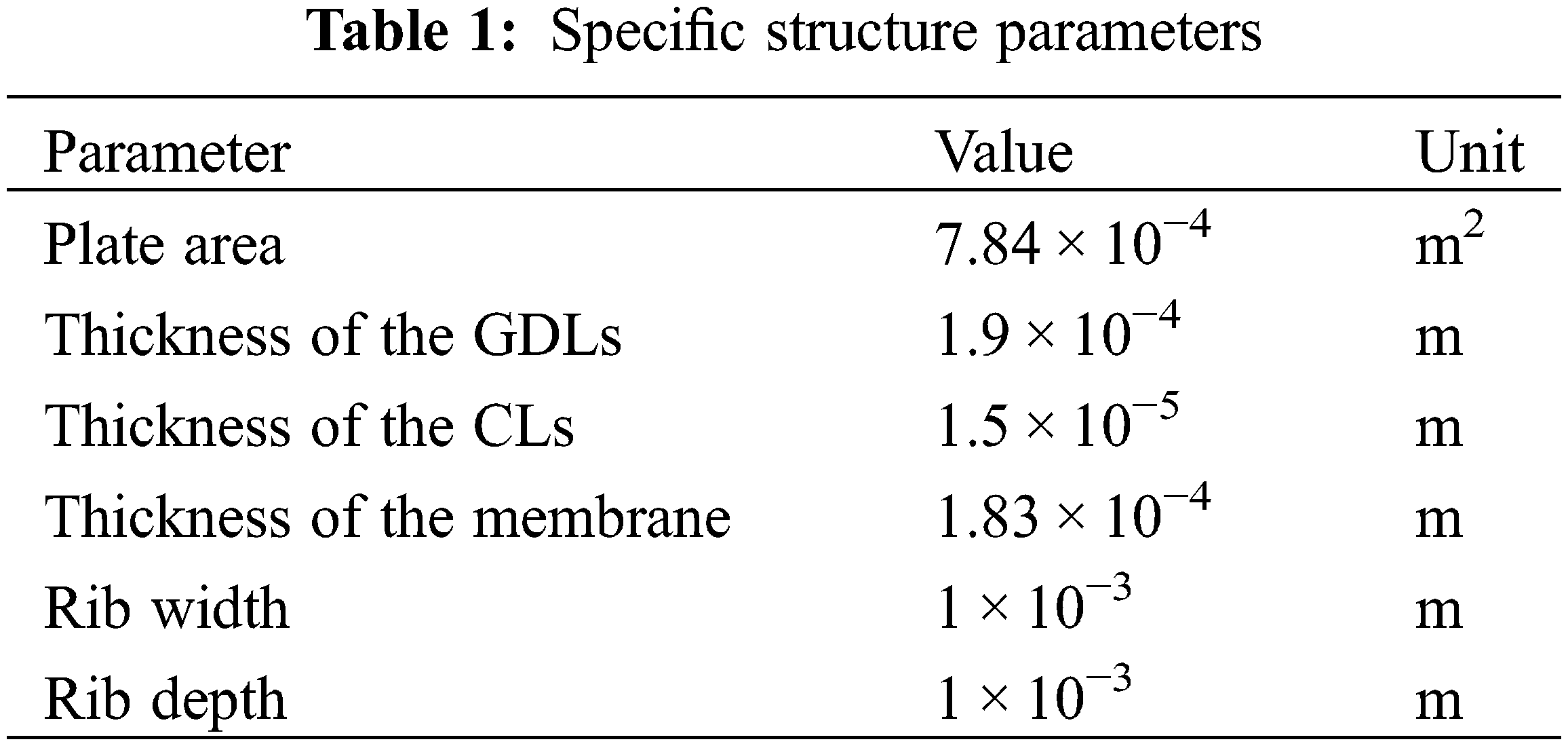
This paper proposes a new spiral flow field with a bypass. Fig. 1a shows the overall structure, which consists mainly of a single spiral channel and an incremental bypass from the inside to the outside. The channel and rib sizes remain constant throughout the “rotation.” The air intake mode of the structure is the central air intake, which is beneficial to maximizing the distribution of reactants. Oxygen diffuses in two directions through the flow channel and bypasses after entering the flow field, and the bypass shape adopts a square design. The bypass can shorten the diffusion distance of some gases and improve the diffusion efficiency. To verify the above perspectives, the above variables were taken as the research focus, and single-cell models of different types of fuel cells were established and simulated. The specific components of the models are shown in Fig. 1b. The specific structure parameters of the fuel cell are shown in Table 1.
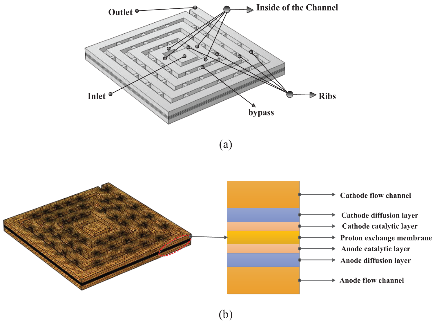
Figure 1: Spiral flow field (a) geometric structure (b) specific components
COMSOL Multiphysics software can simultaneously load different physical fields and couple them. The secondary current distribution, concentrated substance transport and porous medium distribution were used in this study. The calculation method is finite element method, which has great flexibility in discretization. After parameter setting, the steady-state solver is used to couple the three physical fields for calculation. The first-order linear discretization is used in the module involving fluid flow and transfer, and the Brinkman module involving the coupling part is discretized by P1 + P1, which can obtain more accurate solutions [34–36].
The internal situation of PEMFCs is complicated during the chemical reaction. Meanwhile, gas diffusion, water transfer, and the electrochemical reaction of the catalytic layer occur. They interact with and influence each other [37]. The governing equation used in this paper is as follows:
(1) Mass conservation equation
where ε, Sm, and u represent the porosity, the quality source term, and the velocity, respectively.
(2) Momentum conservation equation
where P indicates the fluid pressure (Pa), μ indicates the dynamic viscosity, and Su indicates the momentum source term. In the flow channel, Su = 0.
(3) Energy conservation equation
where CP is the average specific heat capacity of mixing, T indicates the temperature, K indicates the thermal conductivity, and SQ indicates the energy source term, which includes the heat generated by the reaction (which occurs at the surface of the CL) and the heat generated by the evaporation or condensation during phase transformation.
(4) Component conservation equation
The component conservation equation is:
where xirepresents the mass fraction of different components (i = 1, 2 …, N), ε is porosity, and Siis the component source term.
(5) Charge conservation equation
The specific expression of charge conservation equation is:
where δ and Φ represent the solid phase conductivity and the solid potential, respectively. S is the volume transfer current.
(6) Electrochemical equation
The main reaction process on the anode side is as follows:
Local current on the anode side is expressed as:
Similarly, as the focus area of this study, the main reaction process at the cathode side is as follows:
Local current at the cathode side is expressed as:
where η is the over potential, and i is the reference exchange current density.
(7) Liquid water transport equation
The presence of liquid water can make the membrane fully wet, which is conducive to ensuring the reaction rate. However, large droplets will cause pore blockage and affect the mass transfer efficiency. The transmission mechanism of water is as follows:
where ρ and s are the density and transport rate of water, respectively. rw is the condensation rate. In the porous media region, the specific expression of the right term is:
where K and Pcap are the absolute permeability and the capillary pressure, respectively. The contact angle between the droplet and the porous layer surface has different effects on the capillary pressure.
In Eqs. (12) and (13), σs represents the surface tension, and θcon is the contact angle between the water droplets and the porous layer.
1. The fuel cell operating conditions are stable.
2. The flow process of the fuel cell is laminar, and the reactant is ideal gas.
3. The PEM of the fuel cell is electrically insulated.
4. Each reaction gas is ideal and incompressible.
5. The porous media of the fuel cells are isotropic and homogeneous.
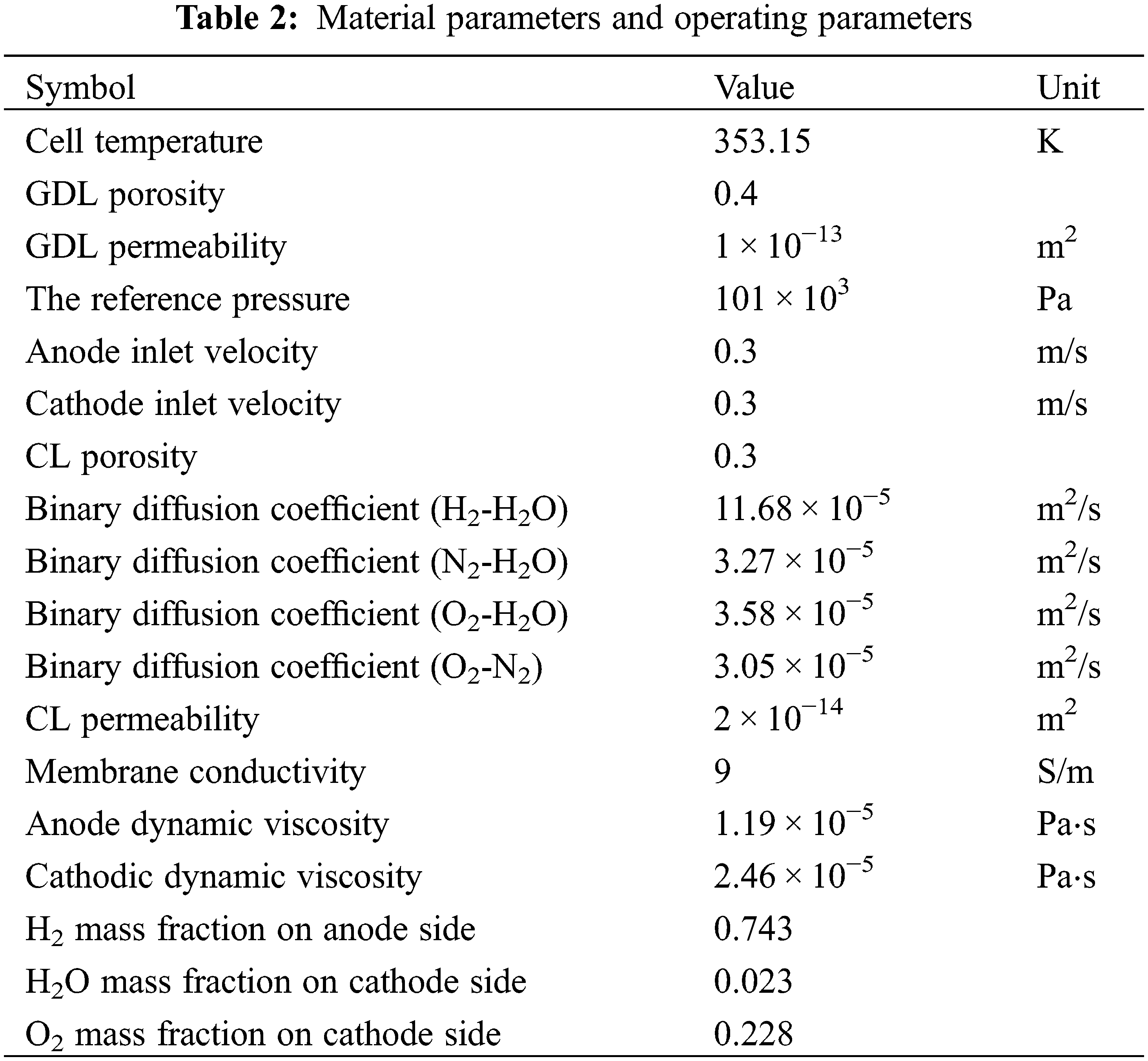
To ensure the stability of the calculation process, the necessary boundary conditions should be set. The mass inlet and the pressure outlet are used for the inlet and outlet boundaries, respectively. The anode collector is grounded by the end face, the cathode is set as the operating voltage, and the rest of the wall boundary is set as no slip. Table 2 shows the empirical parameters used in charge transfer and fluid diffusion in this model [38,39].
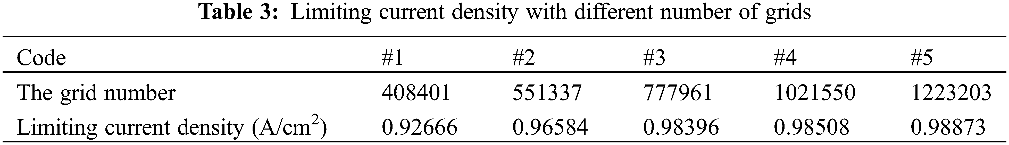
Given the different requirements for calculation accuracy at different PEMFC structures, meshing is a complex process. To ensure that the calculation results are unaffected, the number of grids is divided into five types, namely, 408401, 551337, 777961, 1021550, and 1223203. After simulation calculation, the limiting current density distribution corresponding to the five grid densities is shown in Table 3. The output current tends to stabilize when the grid number exceeds #3 (777961). This shows that the #3 grid used in this paper meets the calculation requirements.
2.6 Validation of Model Rationality
To ensure the rationality of the model involved in this paper, a 3D flow field structure with the same size as that used by Xie et al. was reconstructed, and built-in physical parameters with the same working conditions were provided [39]. This approach was taken because the spiral flow field adopts the same inlet mode as the radial flow field proposed by Xie. We similarly compare the experimental and simulated values of the leaf vein model constructed by Lian et al. [40]. The experimental part was completed on a professional test platform. Many types of PEM exist, and this type was produced by DuPont colorless transparent Nafion 117. In addition, carbon paper is used by Toray (TORAYCA). The accurate test was carried out on the premise of assembling the necessary parts such as hydrogen generator, display and cooling system and ensuring the sealing. Fig. 2 shows that under the two working conditions, the experimental and simulation results are consistent. Therefore, the model is correct.
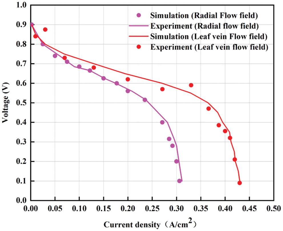
Figure 2: Simulation results were compared with the reference experiment
To determine the effect of the bypass number and the cross-section size on the working efficiency of PEMFCs, the gas diffusion capacity and water displacement effect between different flow fields were compared. After obtaining the numerical results of the bypass for optimal cell performance, the final model is compared with the traditional flow field to verify whether the model is advanced or not.
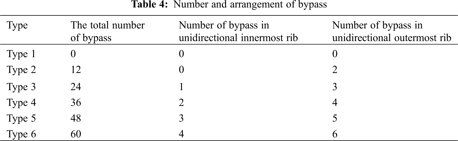
On the basis of the new spiral flow field with a square bypass, six types were designed for the bypasses on the rib. Among them, the number of bypasses in different types of flow field gradually increases with a step length of 12, and the common point is that the difference of the number of bypasses in the adjacent ribs in the same direction is 1. The specific distribution is shown in Table 4.
The U–I and P–I curves shown in Fig. 3 are an important basis for testing the output capacity of the cell. In the mass transfer polarization state, the performance curves in Fig. 3 show significant differences in performance. The results show that the number of bypasses has an important effect on the concentration and flow rate of the feed gas (O2) and the water removal rate at the surface of the CL. The figure shows that the maximum power density of Type 1 is the smallest among the conditions, indicating that the existence of a bypass will significantly improve the actual cell performance.
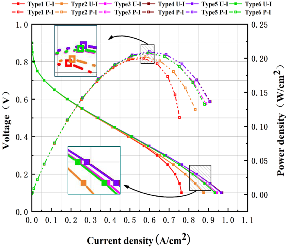
Figure 3: Polarization and power density curves with different numbers of bypass
The diagram also shows that the output power of the fuel cell decreases after increasing with the increasing number of bypasses. The power density curves of Types 4 and 5 nearly coincide completely and are better than those of the other four conditions. Types 4–5 have more bypasses than Types 1–3, increasing the path choices of the reaction gas and enhancing the transfer efficiency in the transfer process from the inner flow channel to the outer flow channel. Although Type 6 has more bypasses than Type 5, excessive bypasses will cause the oxygen movement rate along the flow channel to decline rapidly, which will affect the oxygen concentration and water removal capacity of the outer flow channel, which in turn is sufficient to result in poor output performance. Therefore, the selection of an appropriate number of bypasses is very important for increasing the output power of fuel cells.
3.1.2 Oxygen Layout in GDL/CL Layer
The oxygen concentration of the GDL/CL layer also affects the working efficiency of the fuel cell. Insufficient oxygen concentration can easily cause the chemical reaction rate and the hydrogen utilization to decrease; an extremely high oxygen concentration will lead to an extremely violent chemical reaction and cause the reaction site temperature to continuously increase, causing serious and permanent damage to the membrane electrode assembly. Fig. 4 compares the oxygen molar concentration on the GDL/CL surface in the spiral flow field of six different bypass numbers. The result shows that the oxygen molar concentration at the GDL/CL interface gradually decreases along the channel direction with the highest point at the inlet due to the large amount of oxygen consumed in the chemical reaction process as oxidant.
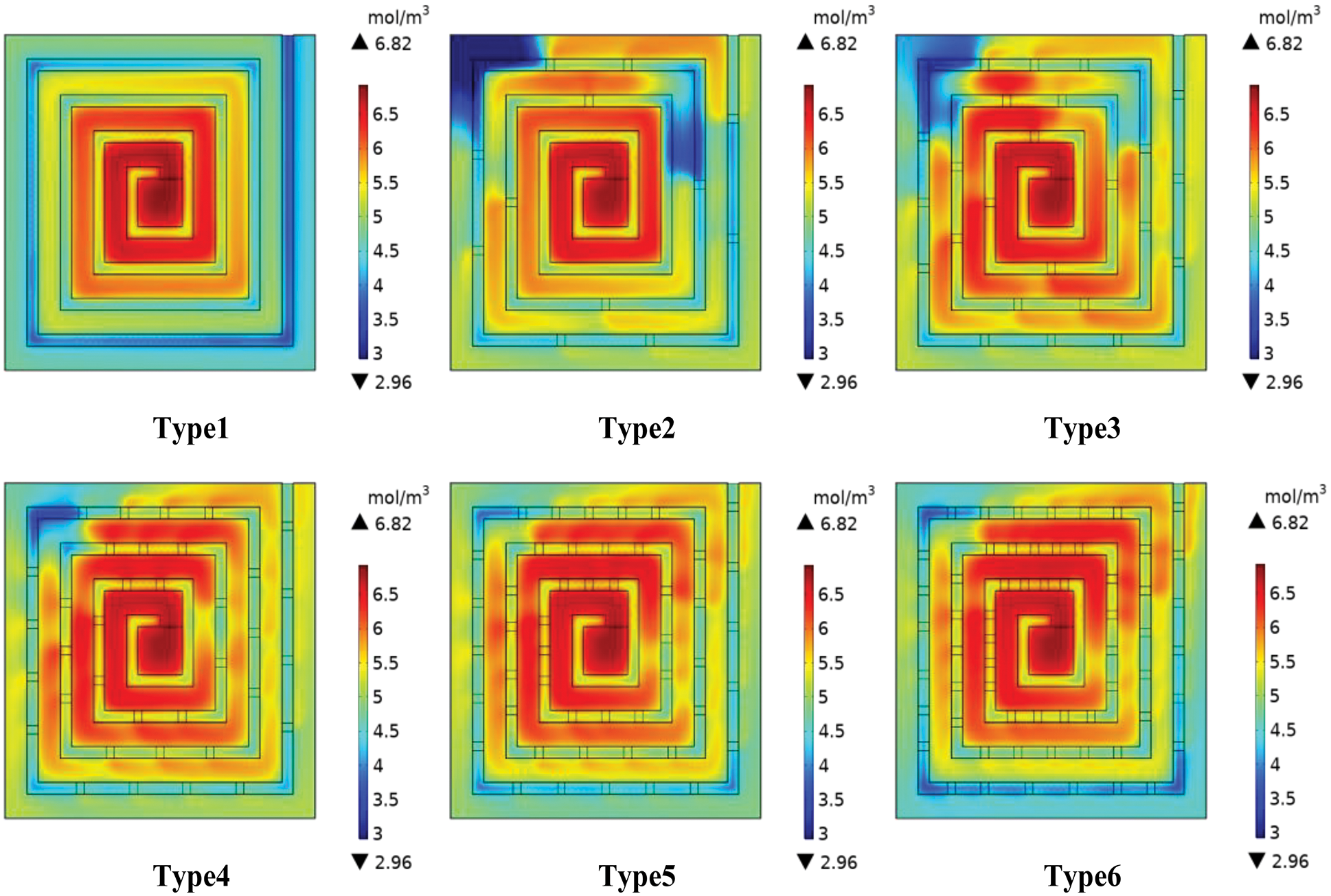
Figure 4: Oxygen distribution in GDL/CL layer of different flow fields
Fig. 4 shows that, after entering the flow channel, the gas gradually diffuses in the form of forced flow along the initial channel structure due to the single-channel spiral structure flow channel type; the addition of bypass increases the choices of oxygen transfer routes, and the incremental arrangement becomes highly conducive for reducing the oxygen starvation effect in the outer flow channel. Compared with that of the other three types, the oxygen is not uniformly dispersed in the GDL/CL layer of Types 1–3. Especially in Type 1, the oxygen concentration is obviously inadequate under the outermost rib and channel. A large area of hypoxia appeared at the corner of the outermost flow channel in Types 2–3, whereas this phenomenon was not obvious in Types 5–6, indicating that appropriately increasing the number of bypasses could significantly improve the gas diffusion capacity in the entire flow channel. The overall oxygen distribution in the GDL/CL layer of Types 4 and 5 is very similar. For Type 6, the oxygen starvation was relatively obvious under the outer flow channel and the rib because the diffusion resistance of oxygen in the direction perpendicular to the flow channel was small and the diffusion ability of oxygen in the direction along the flow channel was relatively weak when too many bypasses were used. Insufficient oxygen power in the outer channel results in the continuous condensation of water molecules, which is not conducive to the normal diffusion of oxygen, which is verified in the next section.
3.1.3 Water Layout in the Flow Channel
Fig. 5 compares the molar concentration of liquid water in six types of cathode channels at the operating voltage of 0.55 V. The liquid water in the cathode channel is produced by the redox reaction on the surface of the CL, and the small droplets form large water blocks after polymerization. Excessive residual will not only hinder the normal transmission of gas but also reduce the movement rate of oxygen in the flow channel, resulting in excessive concentration polarization loss. The diagram also shows that the effect of water removal near the bypass outlet is good. Compared with the single-channel water removal shown in Type 1, the scavenging ability of the bypass to residual water in the flow channel is obvious. The other three flow fields use more bypass flow structures than Types 1–3 to enhance their drainage capacity. The final effect indicates that the molar concentration of water in the flow channel decreased significantly. This phenomenon occurred because the bypass outlet has oxygen from the flow channel and bypasses two directions, liquid water requires fast-moving oxygen to be expelled, bypass water removal can be considered as radial water removal, greatly shortening the distance of oxygen to carry water, which makes the water inside the inner flow channel more convenient discharge.
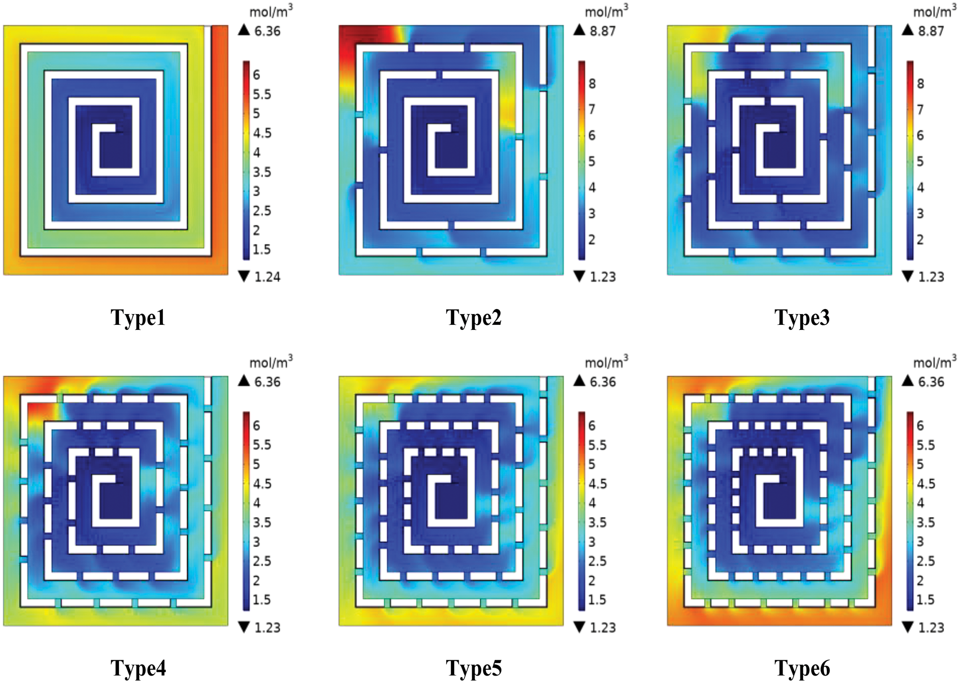
Figure 5: Water distribution in cathode channel of different flow fields
The figure also shows that compared with Types 4 and 5, the water concentration at the outermost ring of the Type 6 flow channel exhibited a slight increase because, due to the influence of centrifugal force, excessive bypasses will result in the relative decrease of the oxygen content and movement rate in the main channel, hindering the complete purification the water at a distant location.
3.1.4 Water Layout in Membrane
The water in the channel has a single inhibiting effect on cell performance, and we always want it to be as small as possible by contrast. An extremely high or low water concentration in the membrane is not conducive to the normal operation of the fuel cell because a wet membrane environment is needed to maintain high proton conductivity. However, if the water generated in the electrochemical site cannot be discharged in a timely manner, a thick water layer will form near it, leading to the “flooding” phenomenon, which is not conducive to the subsequent gas entry. Fig. 6 compares the concentration of water in the membrane of the six types of PEMFC at the operating voltage of 0.55 V. Types 5–6 have a more uniform water distribution effect in the membrane than Types 1–3. Therefore, on the one hand, the existence of a bypass contributes to the reverse osmosis of liquid water back to the flow channel; on the other hand, compared when with the flow field with multiple bypasses, water diffusion is inhibited in the local position when the number of bypasses is small, and an obvious flooding area appears at the corner of flow channels of Types 2–3.
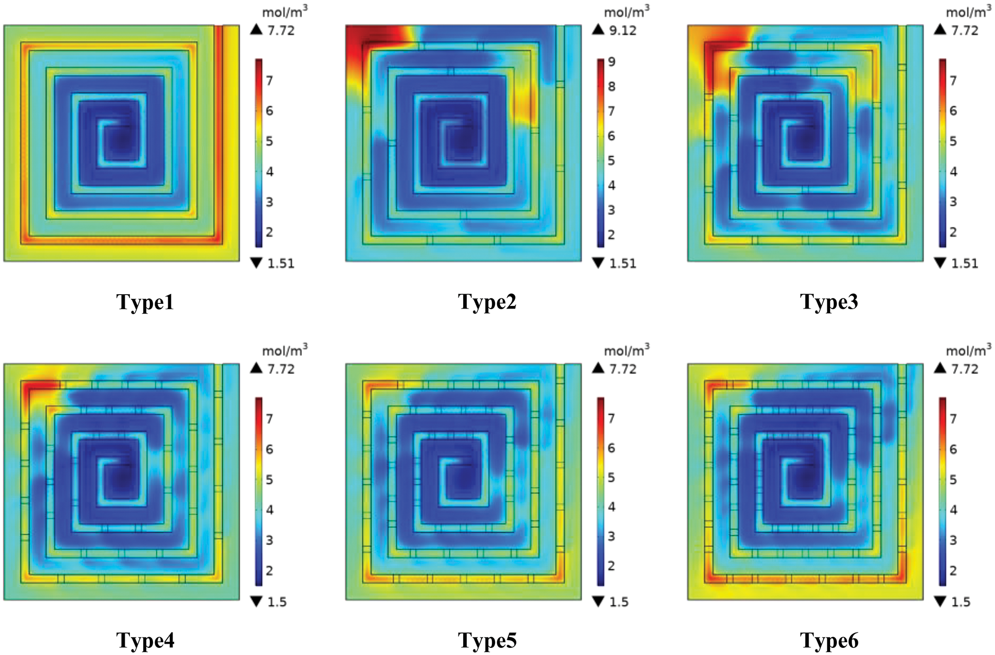
Figure 6: Distribution of water concentration in PEMFC membrane with different number of bypasses
The figure also shows that the area with a serious water aggregation phenomenon in the membranes of Types 4–6 appears below the outermost rib. The overall water content of Types 4–5 is lower and more evenly distributed than that of Type 6. This phenomenon ensures a good reaction process while avoiding “flooding”.
Types 4 and 5 show similar chemical properties in terms of oxygen and water distribution and overall content. However, compared with Type 4 (87.3 pa), the cathode channel pressure drop in Type 5 (74 pa) decreased by 17.97%. This finding indicates that at the same power output, Type 5’s pump power loss is less than that of Type 4’s, which is conducive to improving the efficiency of the fuel cell. Therefore, among the six different flow field structures, Type 5 exhibits the best comprehensive performance.
According to the above analysis, Type 5, which has 48 bypasses, achieves the best comprehensive performance. On the basis of this characteristic and on the premise that the total number of bypasses is 48, the optimal numerical combination of bypass parameters for the new spiral flow field is finally selected by changing the cross-section size of the bypass in this section. The specific bypass cross section size distribution is shown in Table 5.
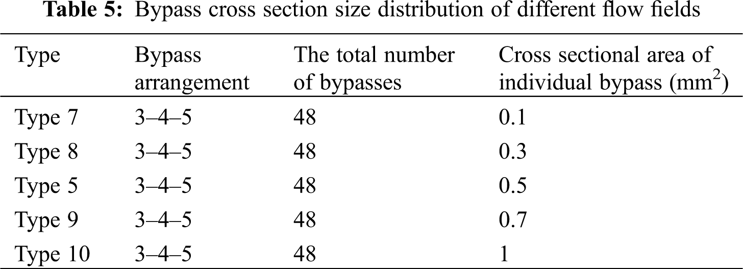
Fig. 7 shows the performance curves of PEMFCs for five different bypass size types. The impact of the bypass cross-section size on the power generation efficiency of the fuel cell is obvious. When the cross section increases, the cell output power begins to decline after reaching its peak. At the same current density, the voltage and power of Type 7 are significantly lower than those of the other four types because an excessively small bypass cross-section area will lead to the low diffusion efficiency of oxygen in the direction perpendicular to the flow channel. In this case, the main channel of oxygen transfer is guided by the geometry of the main channel. The output power of the fuel cell is not ideal when the height of the square bypass is the same as the height of the rib. Fig. 7 shows that the maximum power density of Type 10 is significantly lower than those of Types 5, 8, and 9 because the excessive size of the bypass cross section increases the amount of oxygen diffusion perpendicular to the flow channel. Accordingly, the oxygen movement rate decreases obviously along the flow channel direction, and the oxygen supply is insufficient in the outer flow channel. Therefore, choosing the right size of the bypass cross section can induce an intensified mass transfer effect, which will increase the output performance of the cell.
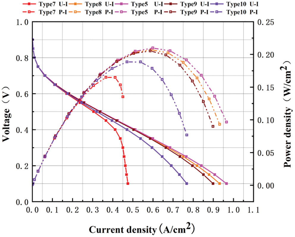
Figure 7: Polarization and power density curves with different bypass cross section sizes
3.2.2 Oxygen Layout in GDL/CL Layer
Fig. 8 compares the oxygen molar concentration in the GDL/CL layer corresponding to the flow fields of five different bypass section sizes. Compared with Type 7, the oxygen concentration distribution uniformity of the other four types of fuel cells is significantly improved. In Type 7, the oxygen supply is significantly inadequate in the outer flow channel near the outlet because the pressure drop of the entire spiral flow field decreases obviously with the appearance of bypass. A small bypass size results in the poor effect of the radial diffusion of oxygen through the pressure difference and insufficient driving force of gas diffusion. In contrast, Type 10 has the largest bypass cross-section size, but the distribution uniformity of the oxygen concentration remains unideal because the oxygen diffusion rate perpendicular to the flow channel direction is fast due to the large size of the bypass. Under the action of centrifugal force, the phenomenon of oxygen aggregation in one direction is obvious. The area with high oxygen concentration only appears at the back of the corner nearest to the inlet, while the oxygen concentration in other locations of the flow field is relatively low. In comparison, the oxygen concentration distribution of the other three types of fuel cells is relatively uniform, especially that of Type 5 (Fig. 9 shows that the oxygen concentration difference is 3.07 mol/L), which is the most uniform.
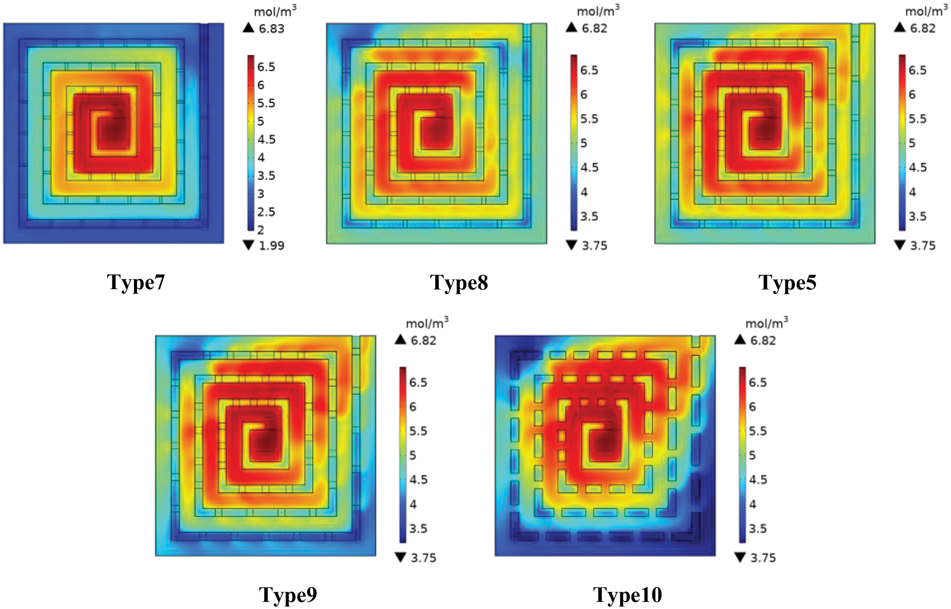
Figure 8: Oxygen distribution in the GDL/CL layer of the flow field with different bypass cross section sizes
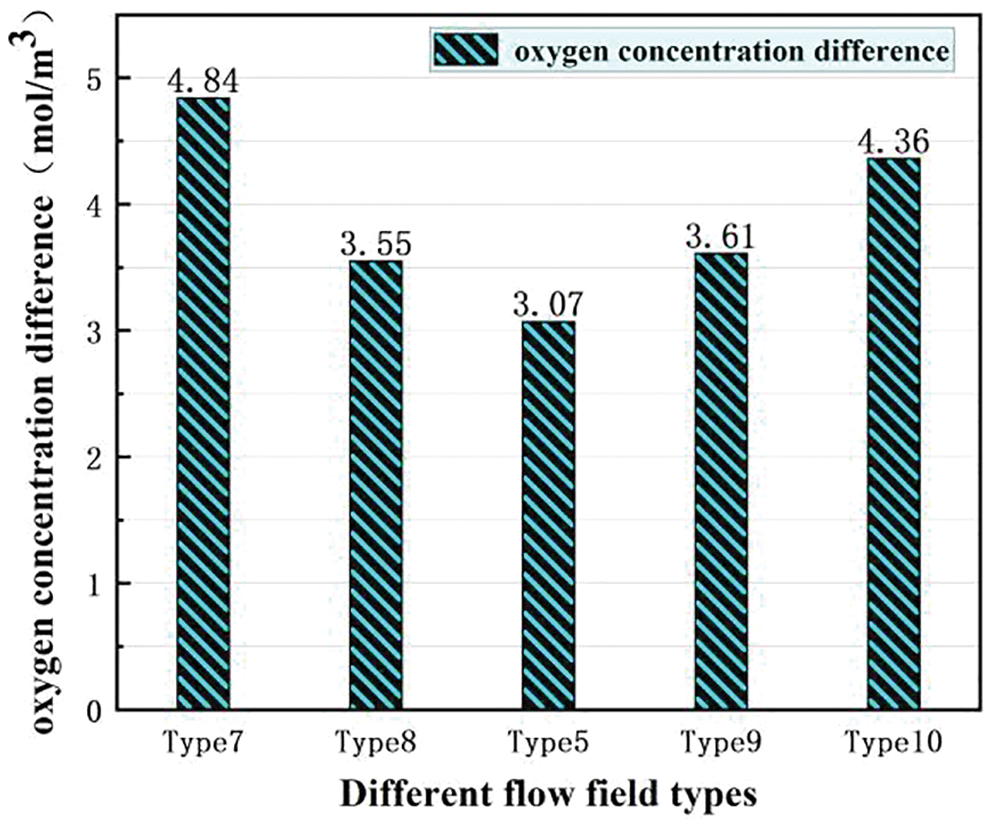
Figure 9: Difference of oxygen concentration with different bypass cross section sizes
3.2.3 Water Layout in the Flow Channel
Fig. 10 shows the distribution of water concentration in the cathode channel of the fuel cell with different bypass cross-section sizes. As shown in the figure, compared with the other two types, water aggregation occurs in the outermost channel of Types 7, 9, and 10. The water accumulation in the Type 7 channel is the most serious. Although the drainage condition of Type 10 is better than that of Type 7, the flow channel with low water content only exists in a part of the flow field. As mentioned earlier, the liquid water concentration is relatively low around the bypass and high at the flow channel corner. The oxygen experiences the vortex phenomenon due to the change in the movement direction at the flow channel corner.
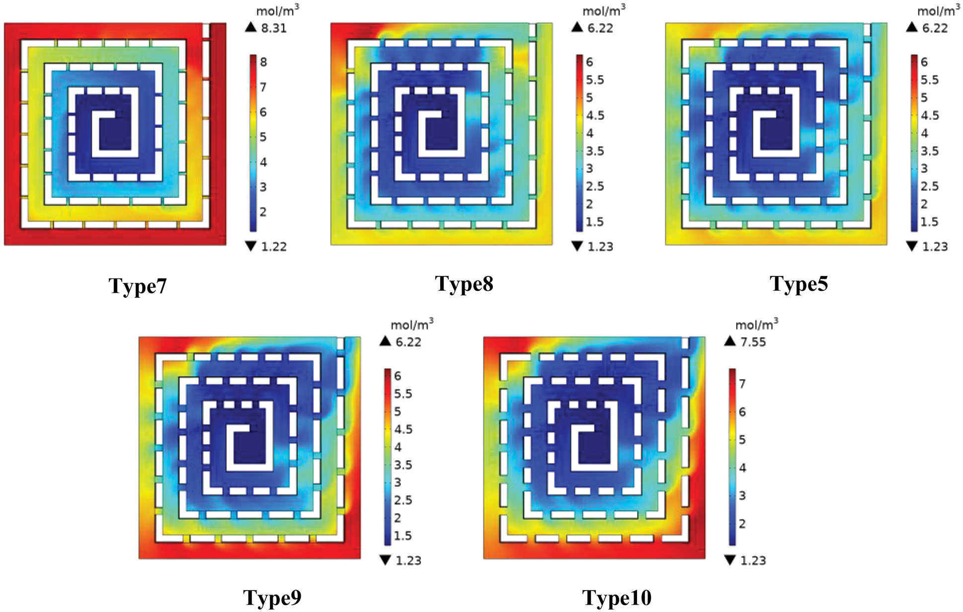
Figure 10: Water concentration distribution in PEMFC channel with different bypass cross section sizes
According to the water concentration difference of the five flow channel types shown in Fig. 11, Types 5 and 8 decreased the least. In addition, compared with the water concentration of Type 5 (4.02 mol/m3), that of Type 8 (4.97 mol/m3) increased by 23.63%. This phenomenon is obvious in the corner area. Therefore, Type 5 has the lowest and most uniform flow channel water content and the best water removal effect.
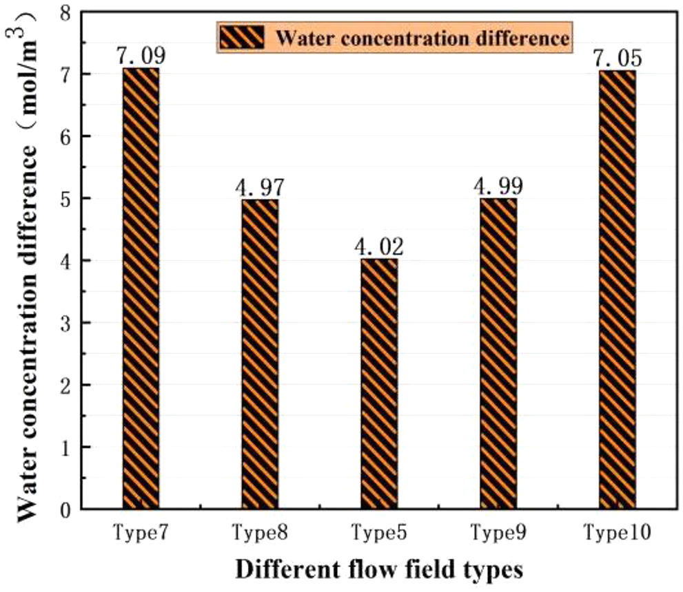
Figure 11: Difference of water concentration with different bypass cross section sizes
3.2.4 Water Layout in the Membrane
Fig. 12 shows the mole concentration of water in the PEMFC membrane of the flow field with different bypass cross-section sizes at the voltage of 0.55 V. The figure shows large areas of high-water concentration in Types 7, 9, and 10 films, especially at the corner of the outermost flow channel, which is prone to “flooding” and affects the normal chemical reaction process. In contrast, Types 5 and 8 are more evenly distributed in terms of water concentration. The overall water concentration distribution of the two flow fields is similar, but the flooding phenomenon occurs in some areas at the corner of the outermost flow channel for Type 8. Combined with all the above characteristics, Type 5 (with 48 bypasses 48 and a bypass cross-sectional area of 0.5 mm2) exhibits the best comprehensive performance.
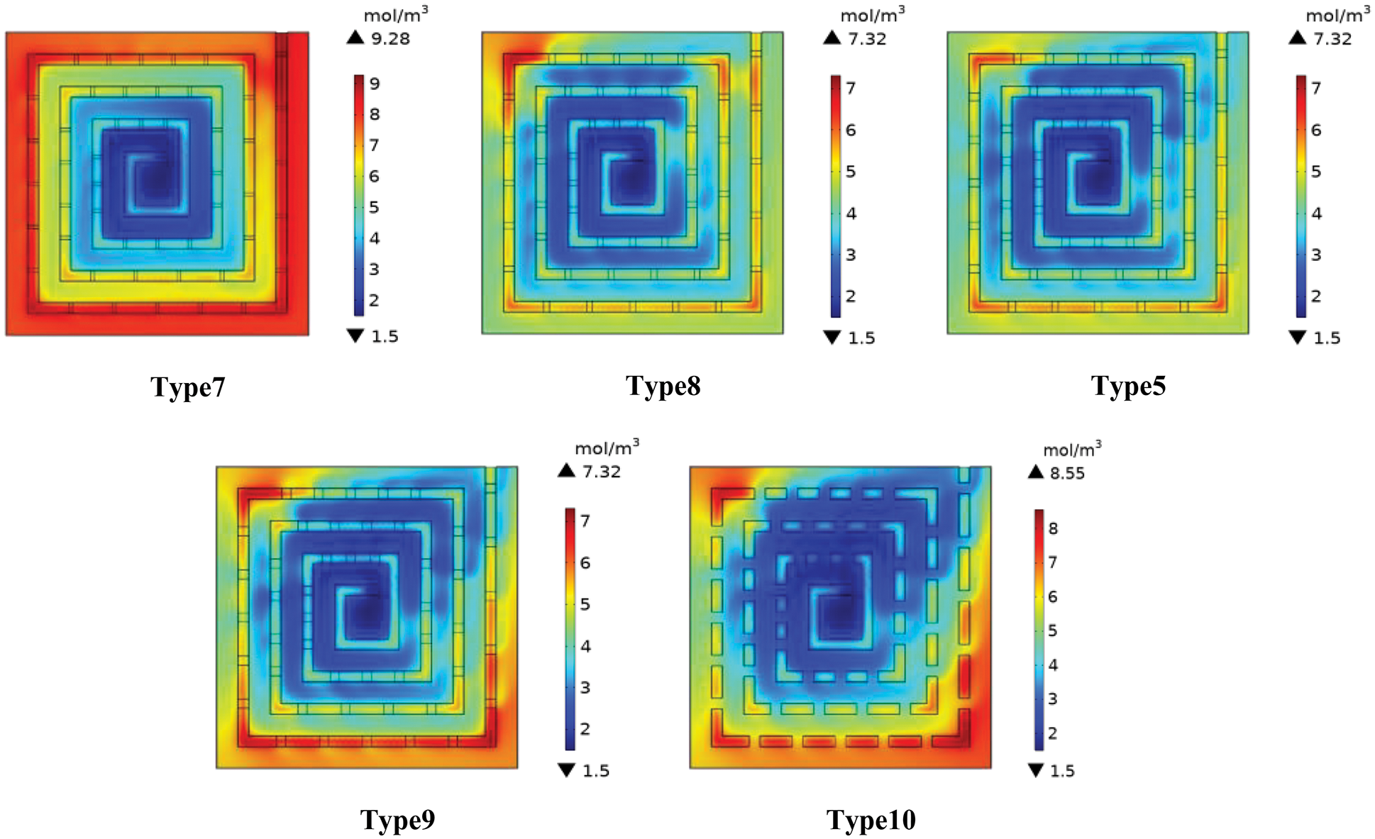
Figure 12: Distribution of water concentration in a membrane flow field with different bypass cross section sizes
3.2.5 Pressure Drop between Different Flow Fields
As an important factor affecting battery efficiency, pressure drop must also be considered. Fig. 13 shows six spiral flow field pressure drop values, of which Type 1 is a conventional regular spiral flow field. The new flow field has a very significant effect in reducing the pressure drop. When the cross-section size is greater than 0.5 mm2, the pressure drop reduction effect is no longer obvious. Compared with Type 1, the pressure drop of Type 5 is reduced by 15.4 times. This reduction can greatly reduce the cost of power output.
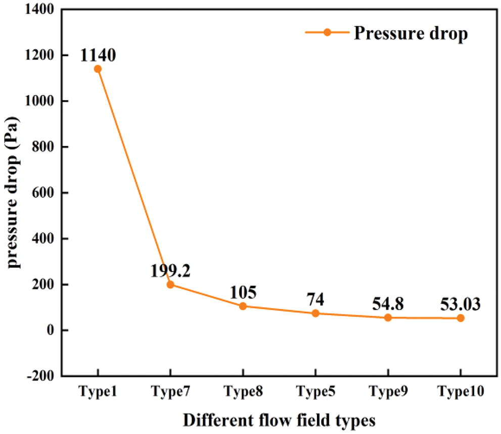
Figure 13: Pressure drop between different flow fields
3.3 Difference between Spiral Flow Field and Traditional Flow Field
As mentioned above, Type 5 has the best numerical combination of bypass parameters, and it is compared with the parallel and serpentine flow fields, which are widely used at present on the premise that the inlet flow rate, plate area, and other external conditions remain unchanged. The comparison results are shown in Fig. 14. In the traditional flow field, the oxygen starvation region is nearly half of the region. The oxygen concentration distribution of Type 5 in the entire reaction interface is relatively uniform, and only a part of the hypoxia area appears under the outermost rib. This phenomenon can also be seen in Fig. 15 and occurred because as the reaction continues, the oxygen near the entrance diffuses efficiently to the reaction interface, and the oxygen diffusion ability of the GDL/CL layer corresponding to the outermost rib is weak. The distribution of water concentration in the three flow fields is similar to that of the oxygen concentration, and flooding occurred at different degrees in the middle of the parallel flow field and the back of the serpentine flow field. In contrast, Type 5 is more evenly distributed in water concentration and has the best comprehensive performance.
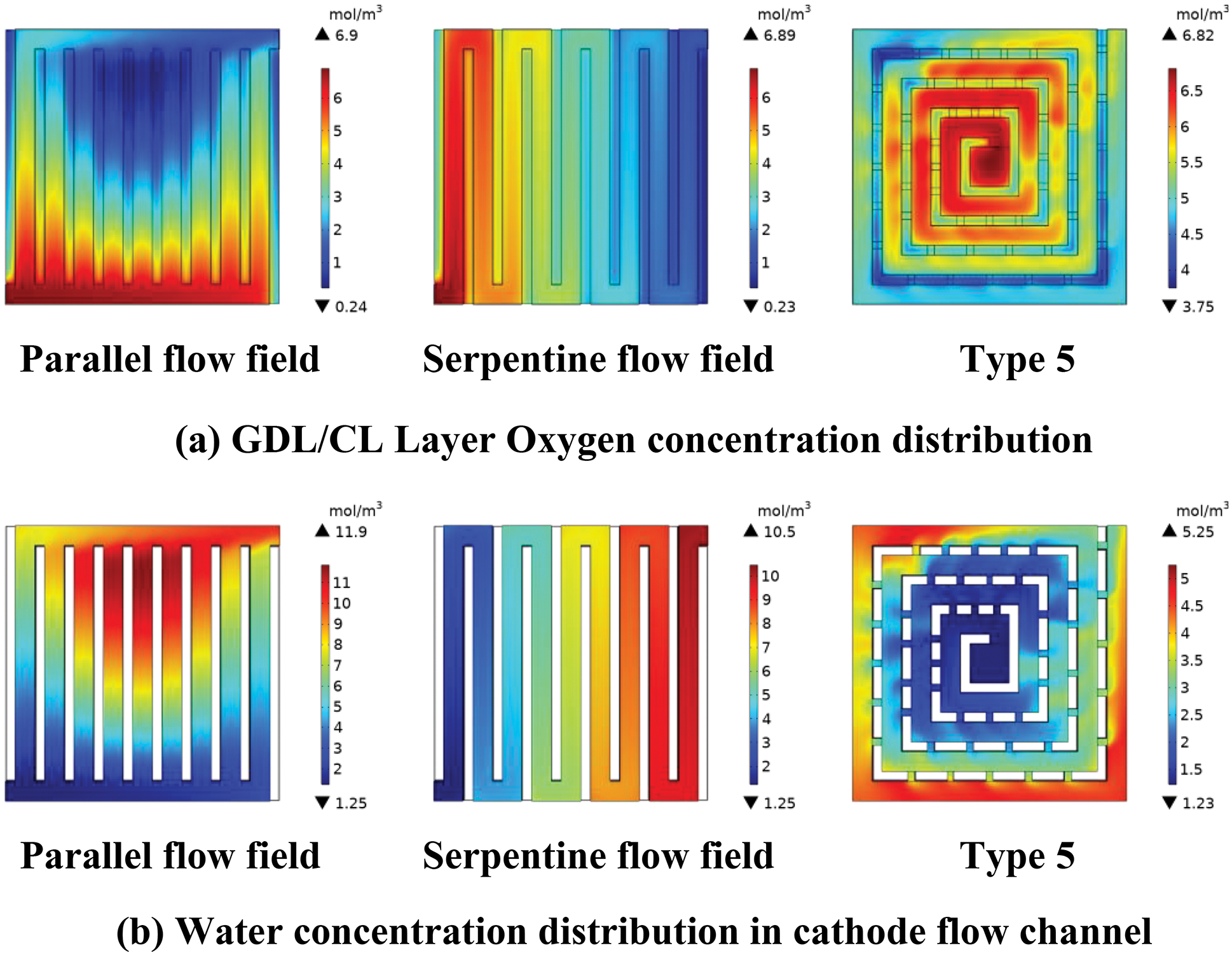
Figure 14: Flow field of three different types (a) GDL/CL oxygen levels (b) Flow channel water content
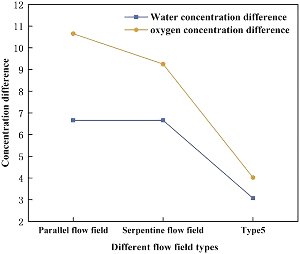
Figure 15: GDL/CL oxygen concentration difference and water concentration difference in the cathode flow channel of different flow field types
Notably, the flow field structure designed by Xie and Lian adopts size parameters similar to those of Type 5 [39,40]. The maximum power density (0.21 W/cm2) of Type 5 is still much higher than that of Xie (0.12 W/cm2) and Lian (0.18 W/cm2) under the premise of small intake speed. Experimental verification further indicates that the new spiral flow field has certain advantages.
In this paper, a single channel spiral flow field with bypass is designed, and the number of bypasses and the cross section of the bypass were taken as the research focus. Through CFD simulation analysis, the optimal numerical combination of bypass parameters was determined. The best type of flow field was evaluated through comparison with the traditional flow field, further verifying the advanced and practical nature of the best type identified.
When the number of bypasses is changed, the cell performance also varies greatly. Type 4 (with 36 bypasses) and Type 5 (with 48 bypasses) have a higher output power than the other types at the same current density. The maximum power density of Type 5 (with 48 bypasses) is increased by 4.87% compared with that of the non-bypass spiral flow field because an appropriate increase in the number of bypasses can increase the diffusion path of oxygen, and the pressure difference between adjacent flow channels on the same side makes part of the oxygen adopt the diffusion perpendicular to the flow channel, which improves the diffusion efficiency. Meanwhile, the increase of bypasses is also conducive to part of the residual liquid water in the inner flow channel through the diffusion path of oxygen in a way perpendicular discharge to the flow field. However, the output power of the fuel cell is not ideal when the number of bypasses is extremely high. Compared with Type 6 (with 60 bypasses), the maximum power density of Type 5 (with 48 bypasses) is increased by 11.29% because the flow channel, as the main drainage path, is more important than the bypass, and an excessive number of bypasses will cause the oxygen movement rate to decrease rapidly along the flow channel direction.
The bypass cross-section size is also a key factor affecting cell efficiency. An appropriate bypass size can improve the overall diffusion efficiency of oxygen. An extremely large bypass cross-section size will result in high oxygen molar concentration in one side of the flow field and an extremely low concentration in other parts. This phenomenon results in poor oxygen concentration distribution uniformity and water removal ability. If the bypass cross-section size is extremely small, then the diffusion effect of oxygen perpendicular to the flow channel is not obvious. Compared with the non-bypass spiral flow field, the pressure drop of the spiral flow field with a small bypass size is extremely low, and the ability of oxygen to reach the outer flow channel is weak, which can be the worst situation. therefore, Type 5 (with 48 bypasses 48 and a bypass cross-sectional area of 0.5 mm2) exhibits the best comprehensive performance.
Funding Statement: Thanks to Major Scientific and Technological Innovation Projects in Shandong Province (2018-CXGC0803) for the financial support of this article.
Conflicts of Interest: The authors declare that they have no conflicts of interest to report regarding the present study.
References
1. Mohammedi, A., Sahli, Y., Moussa, H. B. (2020). 3D investigation of the channel cross-section configuration effect on the power delivered by PEMFCs with straight channels. Fuel, 263, 116713. DOI 10.1016/j.fuel.2019.116713. [Google Scholar] [CrossRef]
2. Ijaodola, O. S., El-Hassan, Z., Ogungbemi, E., Khatib, F. N., Wilberforce, T. et al. (2019). Energy efficiency improvements by investigating the water flooding management on proton exchange membrane fuel cell (PEMFC). Energy, 179, 246–267. DOI 10.1016/j.energy.2019.04.074. [Google Scholar] [CrossRef]
3. Li, W., Zhang, Q., Wang, C., Yan, X., Shen, S. et al. (2017). Experimental and numerical analysis of a three-dimensional flow field for PEMFCs. Applied Energy, 195, 278–288. DOI 10.1016/j.apenergy.2017.03.008. [Google Scholar] [CrossRef]
4. Chen, H., Guo, H., Ye, F., Ma, C. F. (2020). Experimental investigations on cell performance of proton exchange membrane fuel cells with orientated-type flow channels. Journal of Energy Engineering, 146(6), 04020062. DOI 10.1061/(ASCE)EY.1943-7897.0000717. [Google Scholar] [CrossRef]
5. Cooper, N. J., Smith, T., Santamaria, A. D., Park, J. W. (2016). Experimental optimization of parallel and interdigitated PEMFC flow-field channel geometry. International Journal of Hydrogen Energy, 41(2), 1213–1223. DOI 10.1016/j.ijhydene.2015.11.153. [Google Scholar] [CrossRef]
6. Sauermoser, M., Kizilova, N., Pollet, B. G., Kjelstrup, S. (2020). Flow field patterns for proton exchange membrane fuel cells. Frontiers in Energy Research, 8, 13. DOI 10.3389/fenrg.2020.00013. [Google Scholar] [CrossRef]
7. Fan, L., Niu, Z., Zhang, G., Jiao, K. (2018). Optimization design of the cathode flow channel for proton exchange membrane fuel cells. Energy Conversion and Management, 171, 1813–1821. DOI 10.1016/j.enconman.2018.06.111. [Google Scholar] [CrossRef]
8. Zhang, L., Shi, Z. (2021). Optimization of serpentine flow field in proton-exchange membrane fuel cell under the effects of external factors. Alexandria Engineering Journal, 60(1), 421–433. DOI 10.1016/j.aej.2020.09.007. [Google Scholar] [CrossRef]
9. Chen, X., Yu, Z., Yang, C., Chen, Y., Jin, C. et al. (2021). Performance investigation on a novel 3D wave flow channel design for PEMFC. International Journal of Hydrogen Energy, 46(19), 11127–11139. DOI 10.1016/j.ijhydene.2020.06.057. [Google Scholar] [CrossRef]
10. Marappan, M., Palaniswamy, K., Velumani, T., Chul, K. B., Velayutham, R. et al. (2021). Performance studies of proton exchange membrane fuel cells with different flow field designs–Review. The Chemical Record, 21(4), 663–714. DOI 10.1002/tcr.202000138. [Google Scholar] [CrossRef]
11. Chen, X., Chen, Y., Liu, Q., Xu, J., Liu, Q. et al. (2021). Performance study on a stepped flow field design for bipolar plate in PEMFC. Energy Reports, 7, 336–347. DOI 10.1016/j.egyr.2021.01.003. [Google Scholar] [CrossRef]
12. Xie, Q., Zheng, M. (2021). CFD simulation and performance investigation on a novel bionic spider-web-type flow field for PEM fuel cells. Processes, 9(9), 1526. DOI 10.3390/pr9091526. [Google Scholar] [CrossRef]
13. Chen, X., Yu, Z., Wang, X., Li, W., Chen, Y. et al. (2021). Influence of wave parallel flow field design on the performance of PEMFC. Journal of Energy Engineering, 147(1), 04020080. DOI 10.1061/(ASCE)EY.1943-7897.0000735. [Google Scholar] [CrossRef]
14. Li, C., Xu, X., Hu, H., Mei, N., Yang, Y. (2021). Numerical investigation into the effect of serpentine flow channel with a variable cross-section on the performance of proton exchange membrane fuel cell. International Journal of Energy Research, 45(5), 7719–7731. DOI 10.1002/er.6352. [Google Scholar] [CrossRef]
15. Liu, S., Chen, T., Xie, Y., Zhang, J., Wu, C. (2019). Numerical simulation and experimental study on the effect of symmetric and asymmetric bionic flow channels on PEMFC performance under gravity. International Journal of Hydrogen Energy, 44(56), 29618–29630. DOI 10.1016/j.ijhydene.2019.06.046. [Google Scholar] [CrossRef]
16. Dong, P., Jia, Y., Xie, G., Ni, M. (2019). The energy performance improvement of a PEM fuel cell with various chaotic flowing channels. International Journal of Energy Research, 43(10), 5460–5478. DOI 10.1002/er.4665. [Google Scholar] [CrossRef]
17. Li, W. Z., Yang, W. W., Zhang, W. Y., Qu, Z. G., He, Y. L. (2019). Three-dimensional modeling of a PEMFC with serpentine flow field incorporating the impacts of electrode inhomogeneous compression deformation. International Journal of Hydrogen Energy, 44(39), 22194–22209. DOI 10.1016/j.ijhydene.2019.06.187. [Google Scholar] [CrossRef]
18. Subramaniam, S., Rajaram, G., Palaniswamy, K., Jothi, V. R. (2017). Comparison of perforated and serpentine flow fields on the performance of proton exchange membrane fuel cell. Journal of the Energy Institute, 90(3), 363–371. DOI 10.1016/j.joei.2016.04.006. [Google Scholar] [CrossRef]
19. Cano-Andrade, S., Hernandez-Guerrero, A., von Spakovsky, M. R., Damian-Ascencio, C. E., Rubio-Arana, J. C. (2010). Current density and polarization curves for radial flow field patterns applied to PEMFCs (Proton exchange membrane fuel cells). Energy, 35(2), 920–927. DOI 10.1016/j.energy.2009.07.045. [Google Scholar] [CrossRef]
20. Wang, Y., Wang, X., Qin, Y., Zhang, L., Wang, Y. (2022). Three-dimensional numerical study of a cathode gas diffusion layer with a through/in plane synergetic gradient porosity distribution for PEM fuel cells. International Journal of Heat and Mass Transfer, 188, 122661. DOI 10.1016/j.ijheatmasstransfer.2022.122661. [Google Scholar] [CrossRef]
21. Kerkoub, Y., Benzaoui, A., Haddad, F., Ziari, Y. K. (2018). Channel to rib width ratio influence with various flow field designs on performance of PEM fuel cell. Energy Conversion and Management, 174, 260–275. DOI 10.1016/j.enconman.2018.08.041. [Google Scholar] [CrossRef]
22. Yin, C., Song, Y., Liu, M., Gao, Y., Li, K. et al. (2022). Investigation of proton exchange membrane fuel cell stack with inversely phased wavy flow field design. Applied Energy, 305, 117893. DOI 10.1016/j.apenergy.2021.117893. [Google Scholar] [CrossRef]
23. Ramin, F., Sadeghifar, H., Torkavannejad, A. (2019). Flow field plates with trap-shape channels to enhance power density of polymer electrolyte membrane fuel cells. International Journal of Heat and Mass Transfer, 129, 1151–1160. DOI 10.1016/j.ijheatmasstransfer.2018.10.050. [Google Scholar] [CrossRef]
24. Vazifeshenas, Y., Sedighi, K., Shakeri, M. (2015). Numerical investigation of a novel compound flow-field for PEMFC performance improvement. International Journal of Hydrogen Energy, 40(43), 15032–15039. DOI 10.1016/j.ijhydene.2015.08.077. [Google Scholar] [CrossRef]
25. Zhang, S., Liu, S., Xu, H., Liu, G., Wang, K. (2022). Performance of proton exchange membrane fuel cells with honeycomb-like flow channel design. Energy, 239, 122102. DOI 10.1016/j.energy.2021.122102. [Google Scholar] [CrossRef]
26. Dong, J. H., Liu, S. F. (2012). Numerical simulation of fractal tree-shaped flow field structures in PEMFC. In: Applied mechanics and materials, pp. 32–35. Switzerland: Trans Tech Publications Ltd. [Google Scholar]
27. Zhang, S., Xu, H., Qu, Z., Liu, S., Talkhoncheh, F. K. (2022). Bio-inspired flow channel designs for proton exchange membrane fuel cells: A review. Journal of Power Sources, 522, 231003. DOI 10.1016/j.jpowsour.2022.231003. [Google Scholar] [CrossRef]
28. Juarez-Robles, D., Hernandez-Guerrero, A., Ramos-Alvarado, B., Elizalde-Blancas, F., Damian-Ascencio, C. E. (2011). Multiple concentric spirals for the flow field of a proton exchange membrane fuel cell. Journal of Power Sources, 196(19), 8019–8030. DOI 10.1016/j.jpowsour.2011.05.029. [Google Scholar] [CrossRef]
29. Wang, Y., Xu, H., Wang, X., Gao, Y., Su, X. et al. (2022). Multi-sub-inlets at cathode flow-field plate for current density homogenization and enhancement of PEM fuel cells in low relative humidity. Energy Conversion and Management, 252, 115069. DOI 10.1016/j.enconman.2021.115069. [Google Scholar] [CrossRef]
30. Yin, C., Gao, Y., Li, K., Wu, D., Song, Y. et al. (2021). Design and numerical analysis of air-cooled proton exchange membrane fuel cell stack for performance optimization. Energy Conversion and Management, 245, 114604. DOI 10.1016/j.enconman.2021.114604. [Google Scholar] [CrossRef]
31. Yin, C., Cao, J., Tang, Q., Su, Y., Wang, R. et al. (2022). Study of internal performance of commercial-size fuel cell stack with 3D multi-physical model and high resolution current mapping. Applied Energy, 323, 119567. DOI 10.1016/j.apenergy.2022.119567. [Google Scholar] [CrossRef]
32. Cai, Y., Wu, D., Sun, J., Chen, B. (2021). The effect of cathode channel blockages on the enhanced mass transfer and performance of PEMFC. Energy, 222, 119951. DOI 10.1016/j.energy.2021.119951. [Google Scholar] [CrossRef]
33. Jang, J. Y., Cheng, C. H., Liao, W. T., Huang, Y. X., Tsai, Y. C. (2012). Experimental and numerical study of proton exchange membrane fuel cell with spiral flow channels. Applied Energy, 99, 67–79. DOI 10.1016/j.apenergy.2012.04.011. [Google Scholar] [CrossRef]
34. Behrou, R., Pizzolato, A., Forner-Cuenca, A. (2019). Topology optimization as a powerful tool to design advanced PEMFCs flow fields. International Journal of Heat and Mass Transfer, 135, 72–92. DOI 10.1016/j.ijheatmasstransfer.2019.01.050. [Google Scholar] [CrossRef]
35. Tan, Q., Lei, H., Liu, Z. (2022). Numerical simulation analysis of the performance on the PEMFC with a new flow field designed based on constructal-theory. International Journal of Hydrogen Energy, 47(23), 11975–11990. DOI 10.1016/j.ijhydene.2022.01.243. [Google Scholar] [CrossRef]
36. Valentín-Reyes, J., León, M. I., Pérez, T., Romero-Castañón, T., Beltrán, J. et al. (2022). Simulation of an interdigitated flow channel assembled in a proton exchange membrane fuel cell (PEMFC). International Journal of Heat and Mass Transfer, 194, 123026. DOI 10.1016/j.ijheatmasstransfer.2022.123026. [Google Scholar] [CrossRef]
37. Yan, F., Yao, J., Pei, X. (2022). CFD numerical study of a new crossed inverse Z flow field for PEMFC. International Journal of Electrochemical Science, 17, 220721. DOI 10.20964/2022.07.12. [Google Scholar] [CrossRef]
38. Chowdhury, M. Z., Timurkutluk, B. (2018). Transport phenomena of convergent and divergent serpentine flow fields for PEMFC. Energy, 161, 104–117. DOI 10.1016/j.energy.2018.07.143. [Google Scholar] [CrossRef]
39. Xie, Q., Lian, Y., Zheng, M. (2021). CFD simulation and investigation of a new radial flow field structure on the PEMFC circular bipolar plate. International Journal of Electrochemical Science, 16, 211057. DOI 10.20964/2021.10.48. [Google Scholar] [CrossRef]
40. Lian, Y., Xie, Q., Zheng, M. (2020). Investigation on the optimal angle of a flow-field design based on the leaf-vein structure for PEMFC. Journal of New Materials for Electrochemical Systems, 23(4), 262–268. DOI 10.14447/jnmes.v23i4.a07. [Google Scholar] [CrossRef]
Cite This Article
 Copyright © 2023 The Author(s). Published by Tech Science Press.
This work is licensed under a Creative Commons Attribution 4.0 International License , which permits unrestricted use, distribution, and reproduction in any medium, provided the original work is properly cited.
 Downloads
 Citation Tools