
 Submit a Paper
 Propose a Special lssue
 Open Access
ARTICLE

Analysis of the Hydraulic Performances of a New Liquid Emitter Based on a Leaf Vein Concept
School of Hydraulic and Electric Power, Heilongjiang University, Harbin, 150080, China
* Corresponding Author: Ennan Zheng. Email:
Fluid Dynamics & Materials Processing 2023, 19(8), 2147-2160. https://doi.org/10.32604/fdmp.2023.025556
Received 20 July 2022; Accepted 24 November 2022; Issue published 04 April 2023
 View Full Text
 Download PDF
Abstract
The leaf-vein drip irrigation emitter is a new type of drip emitter based on a bionic structure able to support shunting, sharp turns, and increased dissipation. In the present work, the results of twenty-five tests executed in the framework of an orthogonal design strategy are presented in order to clarify the influence of the geometrical parameters of the flow channel on the hydraulic characteristics of such emitter. The corresponding flow index and head loss coefficient are determined through numerical simulations and model testing. The results show that the flow index of the flow channel is 0.4970∼0.5461, which corresponds to good hydraulic performances. The head loss coefficient of the flow channel is 572.74∼3933.05, which in turn indicates a good energy dissipation effect. The order of influence of the leaf vein flow channel parameters on the flow index can be represented in a synthetic way as a > b > c > d > e, where (a) is the width of the inlet, (b) is the horizontal distance of the front water inlet, (c) is the vertical distance of the inner edge of the front end, (d) is the horizontal distance of the rear water outlet and (e) is the vertical distance of the outer edge of the front end. The flow index increases with d, decreases with a, first decreases, and then increases with b, and first increases and then decreases with the increase of c and e. The coefficient (R2) of the fitted model related to geometric parameters and flow index is 0.9986–0.9999. The relative errors among experimental testing, simulation calculation and predictive estimates are shown to be less than 5%.Keywords
Drip irrigation is one of the high-efficiency water-saving irrigation technologies in agriculture [1]. The pressurized water is transported to the vicinity of crop roots in the field through pipes, and the excess energy of the pressurized water is eliminated by the drip irrigation emitter to achieve uniform irrigation [2]. The flow channel structure could directly affect the uniformity and anti-clogging ability of the drip irrigation system [3–5], while the large structure parameters would cause a decrease in irrigation uniformity, and the small structure parameters would cause the blockage of the irrigation emitter [6]. In serious cases, the whole drip irrigation system would not work normally [7,8]. Many scholars have proposed new design concepts and structure types for drip irrigation emitters [9–11]. The fractal channel of the drip emitter was designed by the fractal theory, and it had a flow index between 0.49 and 0.53, which effectively improved the degree of turbulence of the fluid in the flow [12]. A bidirectional offset flow drip irrigation emitter produced positive and negative two-way flow mixing to increase the energy dissipation effect and improved the hydraulic performance [13].
Plants have been an indispensable part of the biological circulation system. Many inventions and creations originated from the biomimetics of plant structures or forms [14]. Xu et al. [15,16] designed a pit drip irrigation emitter by using plant bionic technology and analyzed the relationship between structural parameters and low-velocity vortex through experiments and numerical simulation. The optimization of flow channel improved the anti-clogging ability by increasing the flow resistance and reducing the low-velocity vortex zone. Xing et al. [17] designed a perforated plate drip irrigation device by the biomimetic xylem perforated plate structure, which established sixteen orthogonal schemes to study the hydraulic performance and energy dissipation mechanism, and found that the hydraulic performance in the high-pressure zone was the best. The bionic design of plant structure had some incomparable advantages over artificial structure design [18,19]. The plant leaf vein was the channel of leaf water transmission, which had good anti-hypertension ability [20,21].
In this study, the structure and function of leaf vein were studied macroscopically, and a leaf vein fractal drip irrigation emitter was proposed. This proposed bionic drip irrigation emitter called a “leaf vein drip irrigation emitter” were examined by experimental and numerical simulation testing [22,23]. Numerical simulation mainly studied the water flow distribution and energy dissipation mechanism [24,25], and the experimental testing was mainly used to study hydraulic performance and energy dissipation effect [26]. The structural parameters of the leaf veins flow channel were optimized by orthogonal experiments [27], and hydraulic performance testing were carried out to calculate the head loss coefficient. It can: (1) obtain the relationship between the flow index and geometry parameters of leaf veins drip irrigation emitter; (2) evaluate the head loss coefficient and influencing factors of flow index; (3) establish and verify the prediction model of flow index. The results will provide a new method for the design of drip irrigation emitters.
2.1 The Bionic Flow Channel Design of Leaf Vein
The veins of plants were the channels of water transfer in leaves, which had a good ability to reduce water pressure [20,21]. The structure and function of leaf veins at the macro scale were studied, and a structure of leaf vein fractal drip irrigation emitter was proposed. The leaf vein structure of Cinnamomum camphora (L.) Presl belongs to the conventional leaf vein shape, which is as a bionic sample tree (Fig. 1a). The tree leaves were heated and boiled in 5% to 10% NaOH solution until the mesophyll rotted. During the heating process, the degree of mesophyll decay was checked regularly to avoid the leaf veins and mesophyll separating due to the long heating time. The boiled leaves were washed several times in pure water, and the mesophyll was washed away along the direction of the veins. The cleaned veins were dehydrated, and the samples were put into a root scanner to obtain the image of the vein distribution (Fig. 1b). The bionic application of drip irrigation structure was performed in the square area in the leaf vein distribution graph. The flow index and flow rate requirements of drip irrigation emitters were pre-researched and tested, and the range of geometric parameters was preliminarily determined. The flow channel design is shown in Fig. 1c, where (a) is the width of the inlet, (b) is the horizontal distance of the front water inlet, (c) is the vertical distance of the inner edge of the front end, (d) is the horizontal distance of the rear water outlet, (e) is the vertical distance of the outer edge of the front end, (h) is the length of the unit structure, and (f) is the width of the unit structure. The horizontal distance between the upper and lower sharp corners is 0.5 mm, h = 2b + 2d + 0.5, f = 2e + 2c + a.
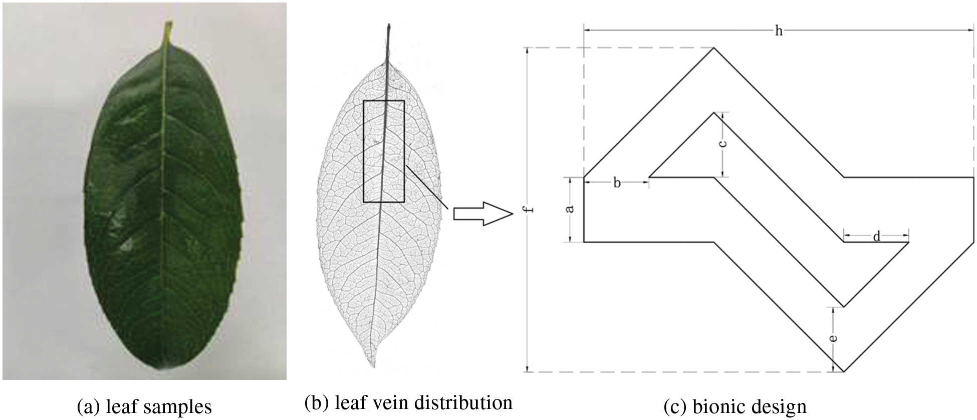
Figure 1: Structure diagram of the emitter unit
2.2 Energy Dissipation Principle and Model Construction
The position of the leaf vein drip irrigation emitter in the pipeline is shown in Fig. 2a, and the energy dissipation principle is shown in Fig. 2b. The leaf vein flow channel can be divided into shunt zone, sharp turn zone, and confluence collision zone under the action of the internal oblique Z-shaped baffle. The pressurized water enter the flow channel where it is first blocked by the oblique Z-shaped baffle, and the water is divided into two parts in the horizontal and inclined directions. The two parts are blocked by the baffle and boundary respectively and underwent a sharp turn. After two sharp turns, the two-part flows are confluent and mixed at the end of the unit, and this process is repeated in the next flow channel unit. After repeated energy consumption, the pressurized water flow will eventually achieve the effect of energy dissipation and steady flow, so that the outflow of the leaf vein drip irrigation device tends to be stable.
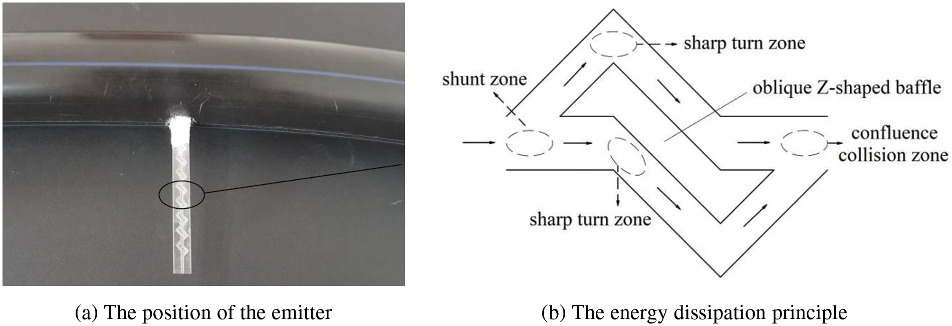
Figure 2: Working principle of leaf vein flow channel
The structure of the leaf vein drip irrigation emitter is shown in Fig. 3, and it is composed of three parts: the water inlet, the leaf vein flow channel, and the water outlet. The leaf vein flow channel includes several periodic unit structures, and each unit structure is composed of an asymmetric toothed structure, and an oblique Z-shaped baffle. The depth of flow channel is 0.6 mm, and the number of flow channel units is 10.
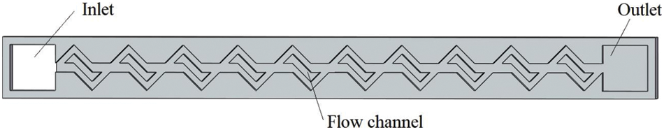
Figure 3: The structure of leaf vein drip irrigation emitter
2.3 Governing Equations and Boundary Conditions of Leaf Vein Drip Irrigation Emitter
The standard k-ε model was used to describe the flow characteristics of the leaf vein flow channel. The finite volume method was used for spatial discretization. The SIMPLEC method was used to couple the pressure and velocity equations, and the convergence accuracy of residual was 1 × 10⁻⁵. The inlet pressure was set to 50 kPa, and evenly increased to 250 kPa in increments of 25 kPa. The outlet conditions of the flow channel was the outflow boundary, and the wall surface of the flow channel was the no-slip condition. The leaf vein flow channel was divided by unstructured mesh of tetrahedron and hexahedron shapes, and a certain mesh refinement was performed at the corners of the leaf vein flow channel structure. The grid density independence test predicted that the pressure drop error was 0.24% (as shown in Table 1), and it was believed that the standard grid had no influence on the calculation results. The mesh size was 0.0603 to 0.0201 mm, and the total number of flow channel meshes was about 125136. The mesh of the leaf vein flow channel is shown in Fig. 4.

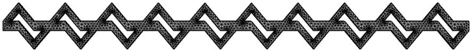
Figure 4: Fluid domain grid
In this study, the SolidWorks computer application was used to design the leaf vein flow channel model, and the equal-scale leaf vein drip irrigation emitter made of plexiglass was engraved with high-precision cutting machine (manufacturing accuracy of 0.01 mm). The experimental test was performed using clean water. Three drip irrigation pipes were set up in the test device, and each pipe was equipped with three drip irrigation emitters, totaling nine leaf vein drip irrigation emitters [27]. The flow rate of the drip irrigation emitter was tested at the working pressure of 50 kPa, and then it was tested every 25 kPa at 1.0–5.0 times the working pressure. Each test time was 5 min, and each test was repeated 3 times. The water output per test was recorded with a measuring cylinder, and the average value was calculated. The relevant regression analysis was carried out to obtain the relationship curve between the flow rate and the pressure. The physical model of the leaf vein drip irrigation emitter is shown in Fig. 5.
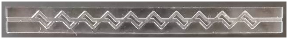
Figure 5: Physical model of leaf vein flow channel
2.5 Orthogonal Experimental Scheme
Generally, the flow rate of the drip irrigation emitter was ≤12 L/h [13], and the flow index and flow rate were used as the basic values of geometric parameters. To meet the expected requirements, the range of values of the various geometric parameters of the leaf vein flow channel was determined as presented in Table 2.

To arrange the test points neatly, regularly, and evenly, the test scheme was representative. L25(56) was selected for the experimental design, combined with the “orthogonality” feature of the orthogonal experimental design. The orthogonal design scheme is presented in Table 3.

2.6 Index Measurement and Calculation Method
The hydraulic performance of the leaf vein drip irrigation channel was analyzed by measuring the flow rate and pressure. The type of flow channel structure directly affected the flow index of the emitter, which was an important factor reflecting its hydraulic performance. The flow index reflected the sensitivity of the flow regime and flow rate to pressure changes. The smaller the flow index had the better the hydraulic performance. In a certain pressure range, the formula is expressed as:
where q is the flow rate under a certain pressure (L/h), H is the inlet pressure (kPa), k is the flow coefficient; x is the flow index.
The energy conservation law was used to calculate the head loss of the flow channel to verify the energy dissipation effect of the leaf vein drip irrigation emitter. The flow in any cross-section from the inlet to the outlet of the leaf vein channel satisfied Bernoulli’s equation (Fig. 6):

Figure 6: Schematic diagram of flow mechanism of leaf vein drip irrigation emitter
where Vn and Pn are the average velocity and pressure at section n, respectively, g is the gravitational acceleration (m/s2), zn is the elevation head at the section (m), ρ is the liquid density (kg/m3), ξn−1 is the dissipation coefficient from section n − 1 to n, λ is the friction head loss, Ln−1 is the length between two adjacent sections (m), D is the hydraulic radius (m), w is the width of the section (m), s is the depth of the section (m).
The terms on both sides of Eq. (2) were added in turn to get:
where L1 + L2 + L3 + … + Ln−1 = L, L is the total length of the leaf vein flow channel. The leaf vein flow channel is placed horizontally, and the potential head is Z1 = Z2 = Z3 = … = Zn. It can be known from the continuity equation:
where Ai (i = 1, 2, …, n) is the flow area at the corresponding section. Substituted Eq. (5) into Eq. (4) to get:
If that,
Eq. (6) can be simplified as:
Can be expressed as:
Or expressed by flow:
where ξ is the head loss coefficient of the leaf vein flow channel, ΔP is the pressure drop from the inlet to the outlet, q is the average flow rate. The ξ is the energy dissipation effect of internal leaf vein structure in drip irrigation emitter. Eqs. (9) and (10) give the physical and mechanical relationship among geometric characteristics, water transport force, and transport driving force of the drip irrigation emitter structure. The energy dissipation mechanism of the leaf vein drip irrigation emitter was thus revealed.
3.1 The Flow-Pressure Relation and Flow Index of Leaf Vein Drip Irrigation Emitter
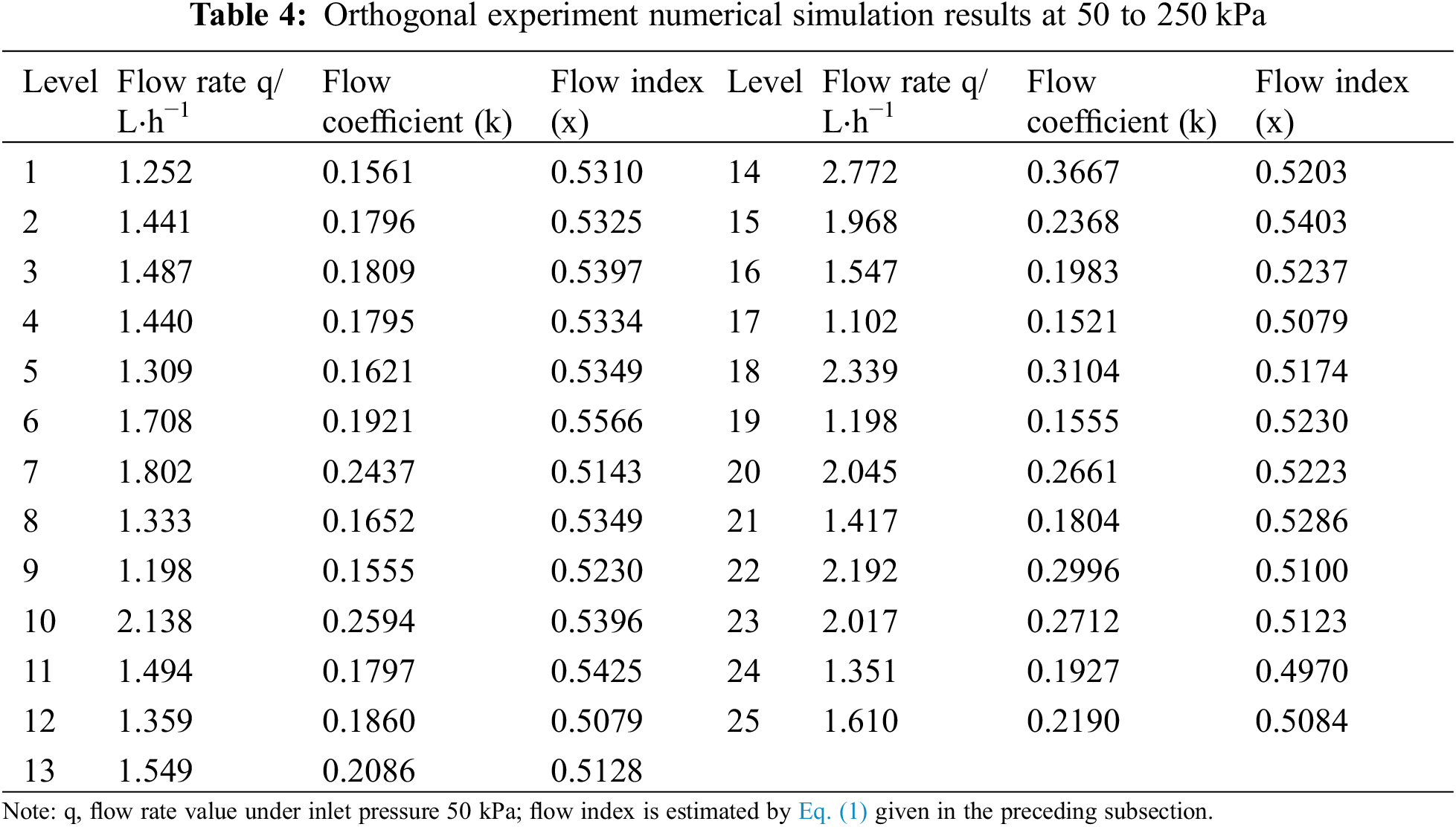
The results of the numerical simulation of the orthogonal experiments are presented in Table 4. The flow and pressure of the leaf vein flow channel were fitted using Eq. (1), and the obtained coefficient of determination was 0.9986–0.9999, indicating that the fitting effect was good.
Experiment schemes 6 and 24 were selected for analysis (Fig. 7), and the root mean square errors of the fitted and simulated values were 0.01387 and 0.0091 L/h, respectively, indicating that the regression equation reflected the correlation between flow and pressure well.
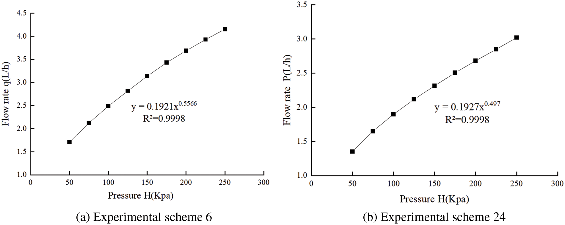
Figure 7: Relationship between flow rate and pressure for experimental schemes 6 and 24
3.2 Energy Dissipation Effect of the Flow Channel
The head loss was calculated by Eq. (10). The results showed that the head loss of the 25 experimental schemes was 572.74∼3933.05, indicating that there was an obvious energy dissipation effect (Table 5).
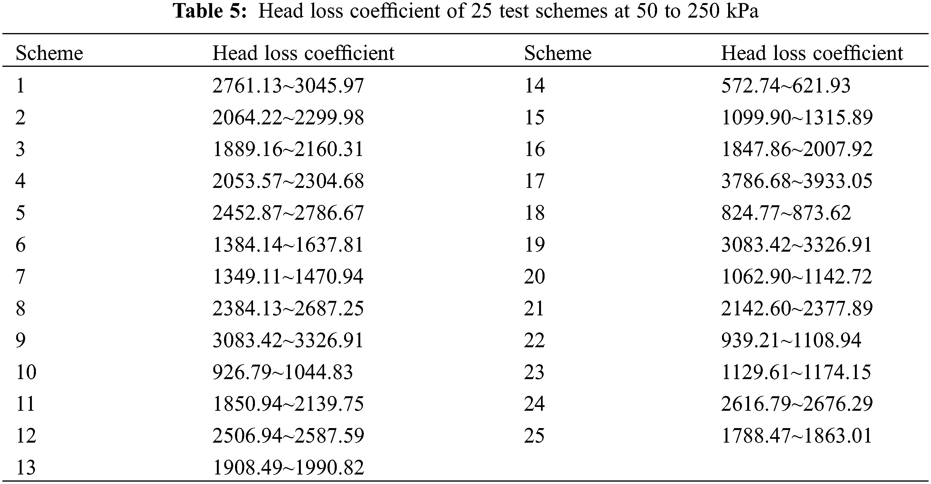
Fig. 8 shows the distribution of the flow velocity at each position inside the leaf vein flow channel under the working pressure of 50 kPa. The velocities are represented by different colors, from blue to red (increasing from blue to red), and it is obvious that the flow velocity was gradually increased. The closer the color of the flow velocity is to red, the higher the flow velocity while, the closer the color of the flow velocity is to blue, the lower the flow velocity. The flow velocity at each point of the leaf vein flow channel does not represent the absolute velocity therefore, comparison of the relative velocity at each point was feasible. The maximum velocity of experimental scheme 14 was 3.4 m/s, and the maximum velocity of experimental scheme 17 was 2.80 m/s. From these two experimental models it can be seen that the velocity distribution of each flow channel unit was similar, and a low-velocity flow was generated at the corners of the flow channel unit. The upper and lower ends of the flow channel of experimental scheme 14 had a complete low-velocity vortex, and the confluence collision zone of the flow channel of experimental scheme 17 had a complete low-velocity vortex, which could effectively improve the energy dissipation effect.

Figure 8: Flow velocity profiles of experimental schemes 14 and 17
3.3 Influence of Factors on Flow Index
The range of values resulting from an analysis based on the simulation values of the flow index (Table 4) are presented in Table 6. The results showed that the order of influence of structure parameters on the flow index was a > b > c > d > e. The optimal solution of the orthogonal experiment was a0.7b0.3c0.7d0.2e0.7.
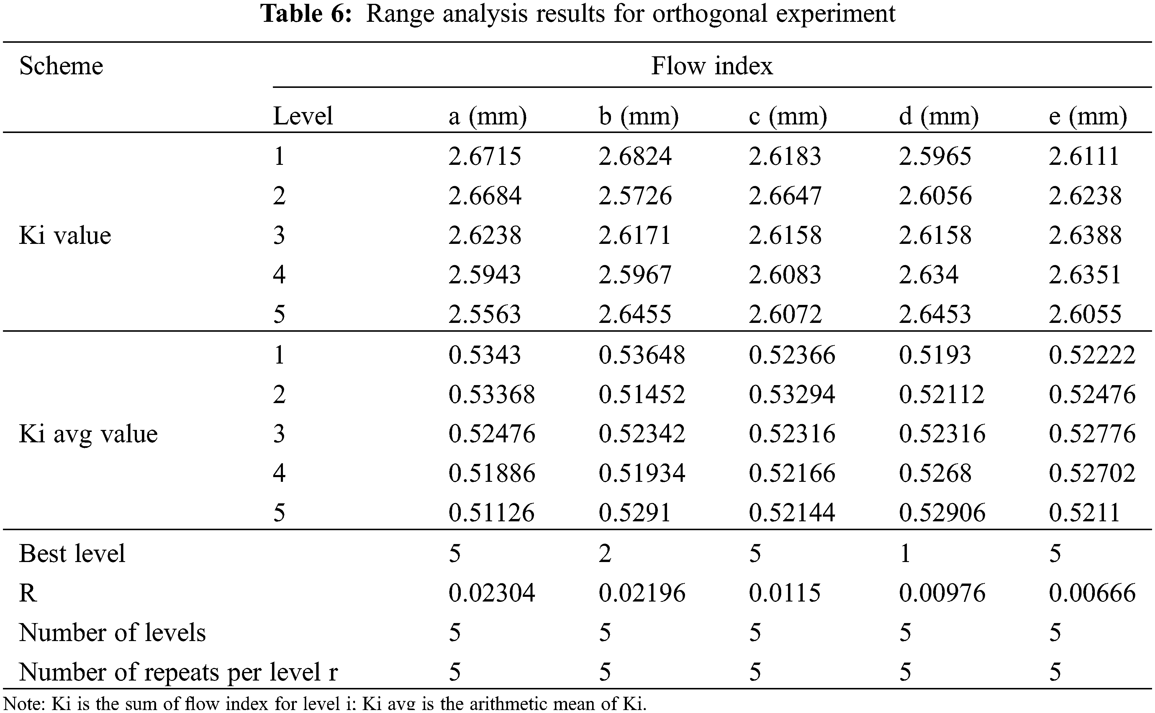
It is evident that the flow index increased with the increase of d, decreased with the increase of a, first decreased, and then increased with the increase of b, and first increased and then decreased with the increase of c and e (Fig. 9).

Figure 9: Effect of structural parameters on flow index
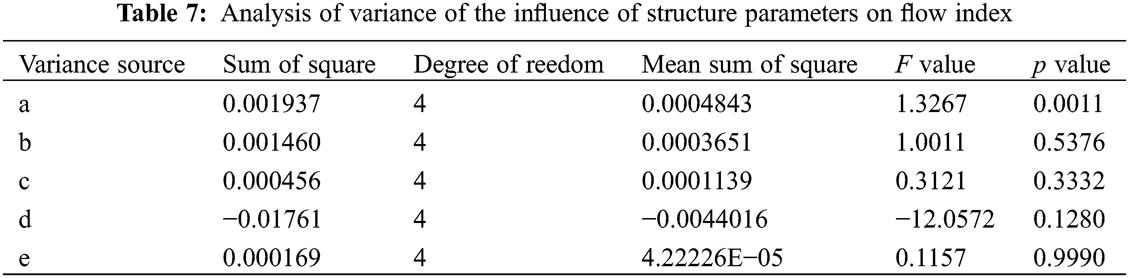
The analysis of variance (Table 7) showed that the p value of factor (a) was less than 0.05, meaning that factor (a) had a significant impact on the flow index. The p values of factors (b), (c), (d) and (e) were greater than 0.05, which means that these factors had no significant effect on the flow index.
3.4 Establishment and Validation of Flow Index Prediction Model
Multiple linear regression analysis was performed on the results of the orthogonal experiments at a confidence level of 95%. The prediction model of the flow index and structural parameters was as follows:
The coefficient of determination R2 on this model was 0.496, the significance level Sig. <0.001. This means that the prediction equation had a significant effect, and the regression model was feasible.
Further, verifying the feasibility of the predictive model, three groups of structure parameters with random values (Table 8) were selected for experimental testing, simulation calculation, and prediction estimation.
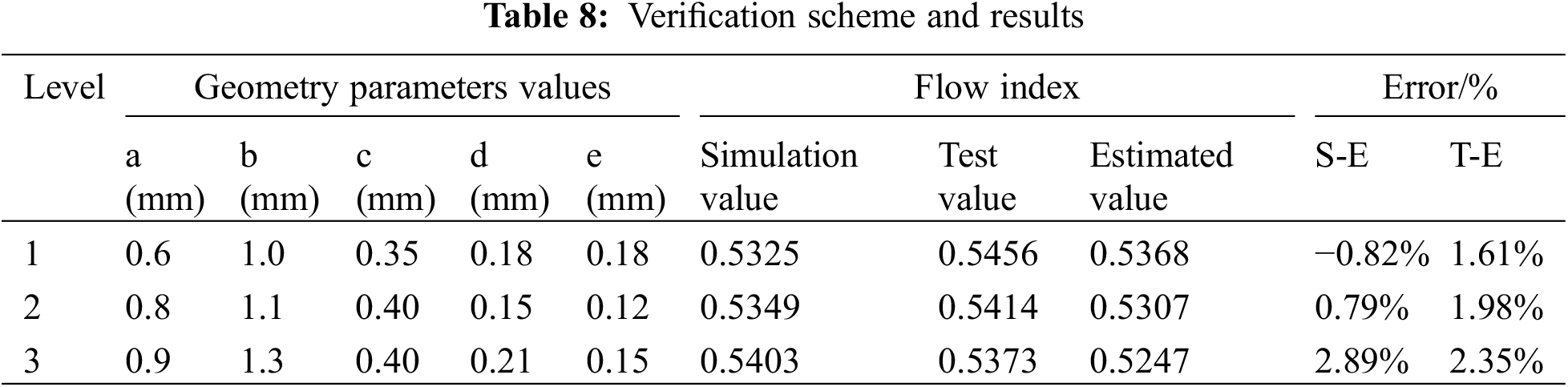
The verification results showed that the relative error (Simulation value-Estimated value; Test value-Estimated value) of the flow index was −0.82%–2.89%, and the predictive model of Eq. (11) could accurately calculate the flow index of the leaf vein flow channel. This method pre-researched and evaluated the flow index of the leaf vein drip irrigation emitter, which reduced the cost of the test and improved the effectiveness of the emitter test arrangement.
In this study, a new emitter flow channel structure based on a leaf vein was proposed, and the structural parameters of the flow channel play a key role in the hydraulic performance and energy dissipation effect [28]. The structural parameters that affect the flow index of the leaf vein drip irrigation emitter were studied by range analysis and analysis of variance. The results showed that the influence of each structural parameter was: a > b > c > d > e, indicating that the inlet width had a great influence on the flow index and therefore, the inlet width should not be set too small (easy to block).
According to the distribution law of flow velocity in the flow channel, the structural parameters had a great influence on the low-velocity vortex distribution. There were complete low-velocity vortices at the upper and lower ends of the flow channel in experimental scheme 14 but at the confluence collision zone of the flow channel of experimental scheme 17. This was similar to what was reported by Xu et al. [15] and Xing et al. [17] when they studied the influence of structural parameters on the hydraulic performance of a pit drip irrigation emitter and a perforated plate drip irrigation emitter respectively. Comparing experimental schemes 14 and 17, it was found that the energy dissipation effect of the flow channel was related to the low-velocity vortex and structural size.
The error between the results of the numerical simulation and the experimental results of the model was within 5%, indicating that the numerical simulation can reliably estimate the flow index. This was similar with the conclusions of Guo et al. [13]. They found that the experimental scheme with the lowest flow index was different from the experimental scheme with the best energy dissipation effect in orthogonal experiments, and the main explanation given was that the structural parameters had different effects on the flow channel size and low-vortex, resulting in different flow index and energy dissipation effects. A previous study [4,5], found that low-vortex will affect the anti-clogging ability of the flow channel. At present, the numerical simulation and experiments focused on the flow index and energy dissipation effect of the new type of emitters. To further improve the performance of leaf vein drip irrigation emitters, there are still some problems to be studied in the future.
1. Optimizing the structure to improve hydraulic performance and energy dissipation effect of drip irrigation emitters.
2. Adding particles of different sizes to study the anti-clogging ability of the flow channel.
In this paper, the relationship between flow index and structural parameters was preliminarily verified and analyzed, and the influence of geometric parameters on flow index was proved. The leaf vein drip irrigation emitters only made an orthogonal analysis on the key parameters. The actual factors that affect its performance may be more than those described in this article, so it needs to be further explored.
1. In this paper, a leaf vein drip irrigation emitter was designed. The flow index obtained by the orthogonal experiment was 0.4970∼0.5566, which had a good hydraulic performance. There were areas/regions of low-vortex at the corners of the flow channel unit, and the energy dissipation effect of the flow channel was related to the low-velocity vortex and structural size. The head loss coefficient of the emitter was 572.74∼3933.05 under the pressure of 0.05∼0.25 MPa, and the energy dissipation effect was obvious, indicating that the structure of the leaf vein drip irrigation emitter was reasonable and had good prospects for real-world application.
2. The flow index was affected by the structural parameters, and the order of influence was a > b > c > d > e. The optimal solution was a0.7b0.3c0.7d0.2e0.7. The flow index increased with the increase of d, decreased with the increase of a, first decreased and then increased with the increase of b, and first increased and then decreased with the increase of c and e. When the p value of factor (a) was less than 0.05, the flow index was significantly affected. When the p values of factors (b), (c), (d) and (e) were greater than 0.05, the flow index was not significantly affected.
3. The flow index prediction model was established. The relative errors among experimental test, simulation calculation and prediction estimation values were less than 5%. The results showed that the prediction model was highly reliable, and it could accurately describe the quantitative relationship between structural parameters and flow index. The hydraulic performance could be predicted at the pressure of 0.05∼0.25 MPa.
Acknowledgement: Thank you for the cooperation and support of the School of Hydraulic and Electric Power, Heilongjiang University, Harbin, China for this research.
Funding Statement: This work was supported by the Basic Scientific Research Fund of Heilongjiang Provincial Universities (2021-KYYWF-0050).
Conflicts of Interest: The authors declare that they have no conflicts of interest to report regarding the present study.
References
1. Souza, W. D. J., Sinobas, L. R., Sánchez, R., Botrel, T. A., Coelho, R. D. (2014). Prototype emitter for use in subsurface drip irrigation: Manufacturing, hydraulic evaluation and experimental analyses. Biosystems Engineering, 128, 41–51. https://doi.org/10.1016/j.biosystemseng.2014.09.011 [Google Scholar] [CrossRef]
2. Li, Y. K., Yang, P. L., Ren, S. M. (2006). A review on the design theory of drip irrigation channel. Transactions of the Chinese Society for Agricultural Machinery, 37, 145–149 (in Chinese). https://doi.org/10.3969/j.issn.1000-1298.2006.02.038 [Google Scholar] [CrossRef]
3. Madramootoo, C. A., Morrison, J. (2013). Advances and challenges with micro-irrigation. Irrigation and Drainage, 62(3), 255–261. https://doi.org/10.1002/ird.1704 [Google Scholar] [CrossRef]
4. Zhang, W. T., Yang, L. H., Wang, J. Y., Zhang, X. H. (2022). Analysis of flow channel structure parameter and optimization study on tooth spacing of drip irrigation tape. Water, 14(11), 1694–1694. https://doi.org/10.3390/W14111694 [Google Scholar] [CrossRef]
5. Yang, B., Wang, J. D., Zhang, Y. Q., Wang, H. T., Ma, X. P. et al. (2020). Anti-clogging performance optimization for dentiform labyrinth emitters. Irrigation Science, 38(3), 1–11. https://doi.org/10.1007/s00271-020-00671-6 [Google Scholar] [CrossRef]
6. Wei, Z. Y., Cao, M., Liu, X., Tang, Y. P., Lu, B. H. (2012). Flow behavior analysis and experimental investigation for emitter micro-channels. Chinese Journal of Mechanical Engineering, 25(4), 729–737. https://doi.org/10.3901/CJME.2012.04.729 [Google Scholar] [CrossRef]
7. Lin, Z., Gary, P. M. (2012). Relationships between common irrigation application uniformity indicators. Irrigation Science, 30(2), 83–88. https://doi.org/10.1007/s00271-011-0264-6 [Google Scholar] [CrossRef]
8. Yang, B., Wu, Y., Wang, J. D., Ma, X. P., Wang, H. T. et al. (2019). Anti-clogging performance analysis and structural optimization simulation of tooth labyrinth irrigator. Journal of Irrigation and Drainage, 38, 84–89. [Google Scholar]
9. Vekariya, P. B., Subbaiah, R., Mashru, H. H. (2011). Hydraulics of microtube emitters: A dimensional analysis approach. Irrigation Science, 29(4), 341–350. https://doi.org/10.1007/s00271-010-0240-6 [Google Scholar] [CrossRef]
10. Mohamed, A. M., Ahmed, I. A. (2017). Gene expression programming approach for modeling the hydraulic performance of labyrinth-channel emitters. Computers and Electronics in Agriculture, 142, 450–460. https://doi.org/10.1016/j.compag.2017.09.029 [Google Scholar] [CrossRef]
11. Yurdem, H., Demir, V., Mancuhan, A. (2015). Development of a simplified model for predicting the optimum lengths of drip irrigation laterals with coextruded cylindrical in-line emitters. Biosystems Engineering, 137, 22–35. https://doi.org/10.1016/j.biosystemseng.2015.06.010 [Google Scholar] [CrossRef]
12. Li, Y. K., Yang, P. L., Ren, S. M., Lei, X. L., Wu, X. B. et al. (2007). Effect of fractal channel design and geometrical parameters on hydraulic performance of dropper. Journal of Mechanical Engineering, 43, 109–114. https://doi.org/10.3321/j.issn:0577-6686.2007.07.020 [Google Scholar] [CrossRef]
13. Guo, L., Bai, D., Wang, X., He, J., Zhou, W. et al. (2016). Hydraulic performance and energy dissipation of an irrigator for two-way offset flow drip irrigation. Journal of Agricultural Engineering, 32(17), 77–82. https://doi.org/10.11975/j.issn.1002-6819.2016.17.011 [Google Scholar] [CrossRef]
14. Liu, W. Y., Peng, Y., Luo, T., Luo, Y. Q., Huang, K. D. (2016). The performance of the vapor chamber based on the plant leaf. International Journal of Heat and Mass Transfer, 98, 746–757. https://doi.org/10.1016/j.ijheatmasstransfer.2016.02.091 [Google Scholar] [CrossRef]
15. Xu, T. Y., Zhang, L. X. (2020). Influence and analysis of structure design and optimization on the performance of a pit drip irrigation emitter. Irrigation and Drainage, 69(4), 633–645. https://doi.org/10.1002/ird.2433 [Google Scholar] [CrossRef]
16. Xu, T. Y., Su, Y. R., Su, Z. M., Zhi, S. T., Zheng, E. N. et al. (2022). Simulation of the hydraulic behavior of a bionic-structure drip irrigation emitter. Fluid Dynamics & Materials Processing, 18(4), 1169–1182. https://doi.org/10.32604/fdmp.2022.018628 [Google Scholar] [CrossRef]
17. Xing, S. B., Wang, Z. H., Zhang, J. Z., Liu, N. N., Zhou, B. (2021). Simulation and verification of hydraulic performance and energy dissipation mechanism of perforated drip irrigation emitters. Water, 13(2), 171. https://doi.org/10.3390/w13020171 [Google Scholar] [CrossRef]
18. Aritra, G., Sara, B., June, Z. B., Ranjan, G., M, M. C. (2014). Enhancing dropwise condensation through bioinspired wettability patterning. Langmuir, 30(43), 13103–13115. https://doi.org/10.1021/la5028866 [Google Scholar] [PubMed] [CrossRef]
19. He, J. K., Mao, M., Li, D. C., Liu, Y. X., Jin, Z. M. (2014). Characterization of leaf-inspired microfluidic chips for pumpless fluid transport. Journal of Bionic Engineering, 11(1), 109–114. https://doi.org/10.1016/S1672-6529(14)60025-1 [Google Scholar] [CrossRef]
20. Liu, W. Y., Luo, Y. Q., Wang, L., Luo, T., Peng, Y. et al. (2016). Water transport in leaf vein systems and the flow velocity measurement with a new method. Journal of Plant Physiology, 204, 74–84. https://doi.org/10.1016/j.jplph.2016.06.022 [Google Scholar] [PubMed] [CrossRef]
21. Xu, T. Y., Zhi, S. T., Su, Y. R., Li, Z. L., Zheng, E. N. (2022). Water transport characteristics of multiple structures of xylem vessels in Magnolia. Forests, 13(10), 1617. https://doi.org/10.3390/f13101617 [Google Scholar] [CrossRef]
22. Al-Amoud, A. I., Mattar, M. A., Ateia, M. I. (2014). Impact of water temperature and structural parameters on the hydraulic labyrinth channel emitter performance. Spanish Journal of Agricultural Research, 12(3), 580–593. https://doi.org/10.5424/sjar/2014123-4990 [Google Scholar] [CrossRef]
23. Piller, M., Nobile, E., Hanratty, T. J. (2022). DNS study of turbulent transport at low prandtl numbers in a channel flow. Journal of Fluid Mechanics, 458, 419–441. https://doi.org/10.1017/S0022112001007704 [Google Scholar] [CrossRef]
24. Zhangzhong, L. L., Yang, P. L., Zheng, W. G., Li, Y. K., Liu, Y. et al. (2021). Effects of water salinity on emitter clogging in surface drip irrigation systems. Irrigation Science, 39(2), 209–222. https://doi.org/10.1007/s00271-020-00690-3 [Google Scholar] [CrossRef]
25. Demir, V., Yurdem, H. U., Yazgi, A., Gunhan, T. U. (2019). Measurement and prediction of total friction losses in drip irrigation laterals with cylindrical integrated in-line drip emitters using CFD analysis method. Journal of Agricultural Sciences, 25(3), 354–366. https://doi.org/10.15832/ankutbd.433830 [Google Scholar] [CrossRef]
26. Yu, L., Li, N., Liu, X., Yang, Q., Li, Z. et al. (2018). Influence of dentation angle of labyrinth channel of drip emitters on hydraulic and anti-clogging performance. Irrigation and Drainage, 68(2), 256–267. https://doi.org/10.1002/ird.2304 [Google Scholar] [CrossRef]
27. Yuan, W. J., Wei, Z. Y., Chu, H. L., Ma, S. L. (2014). Optimal design and experiment for divided-flow emitter in drip irrigation. Transactions of the Chinese Society of Agricultural Engineering, 30(17), 117–124. https://doi.org/10.3969/j.issn.1002-6819.2014.17.016 [Google Scholar] [CrossRef]
28. Hu, Y., Peng, J., Yin, F., Liu, X., Li, N. (2020). Optimization of trapezoidal labyrinth emitter channel based on MATLAB and COMSOL co-simulation. Transactions of the Chinese Society of Agricultural Engineering, 36(22), 158–164. https://doi.org/10.11975/j.issn.1002-6819.2020.22.017 [Google Scholar] [CrossRef]
Cite This Article
 Copyright © 2023 The Author(s). Published by Tech Science Press.
This work is licensed under a Creative Commons Attribution 4.0 International License , which permits unrestricted use, distribution, and reproduction in any medium, provided the original work is properly cited.
 Downloads
 Citation Tools