
 Submit a Paper
 Propose a Special lssue
 Open Access
ARTICLE
Analysis of the Flow Field and Impact Force in High-Pressure Water Descaling
1
Key Lab of Intelligent Equipment Digital Design and Process Simulation, Hebei Province, Tangshan University, Tangshan, 063000,
China
2
Department of Intelligent Manufacturing, Tangshan Vocational College of Science and Technology, Tangshan, 063001, China
* Corresponding Author: Yue Cui. Email:
(This article belongs to the Special Issue: Computational Mechanics and Fluid Dynamics in Intelligent Manufacturing and Material Processing)
Fluid Dynamics & Materials Processing 2024, 20(1), 165-177. https://doi.org/10.32604/fdmp.2023.030311
Received 31 March 2023; Accepted 06 June 2023; Issue published 08 November 2023
 View Full Text
 Download PDF
Abstract
This study aims to improve the performances of the high-pressure water descaling technology used in steel hot rolling processes. In particular, a 2050 mm hot rolling line is considered, and the problem is investigated by means of a fluid–structure interaction (FSI) method by which the descaling effect produced by rolling coils with different section sizes is examined. Assuming a flat fan-shaped nozzle at the entrance of the R1R2 roughing mill, the out- flow field characteristics and the velocity distribution curve on the strike line (at a target distance of 30–120 mm) are determined. It is found that the velocity in the center region of the water jet with different target distances is higher than that in the boundary region. As the target distance increases, the velocity of the water jet in the central region decreases. Through comparison with experimental results, it is shown that the simulation model can accurately predict the impact position of the high-pressure water on the impact plate, thereby providing a computational scheme that can be used to optimize the nozzle space layout and improve the slabs’ descent effect for different rolling specifications.Keywords
High-pressure water descaling technology is used in the hot rolling process of steel, where high temperatures lead to rapid oxidation and dense scale formation of the steel surface. After discharging the hot rolled part from the heating furnace, it enters the descaling box. In the descaling box, the high-speed water jet from the high-pressure water nozzle hits the surface of the rolled piece. The rapid cooling of the rolled piece surface caused the iron oxide scale to crack and be washed away [1,2].
The structure and arrangement of high-pressure water descaling nozzles directly affect the speed, striking force, and range of descaling water [3]. In computational simulation, Giussani et al. used the VOF (VolumeFluentModel) model to simulate the flow field characteristics and jet parameters in the nozzle [4]. Guha et al. analyzed the velocity and pressure of the super high-speed water jet nozzle with the increase in jet distance and verified the linear attenuation of the pressure on the axis [5]. In the high-pressure water scouring process, Maniadaki et al. simulated the target by using FLUENT software, and an experimental comparison was conducted [6]. Urazmetov et al. established a relationship between the geometry and the shear stress of nozzles to identify the parameter that reduced the lifetime of high-pressure nozzles [7]. Zhou calculated the fan nozzle and found that the jet impact force gradually increased with the increase in the nozzle inlet pressure within a certain range [8]. Qiao et al. simulated the atomizing flow field between the nozzle and the spray surface and optimized the structural parameters of the nozzle by using the response surface method [9]. Liu et al. established a numerical model of the flow field based on the liquid–gas flow of the coaxial jet and investigated the laminar fluid velocity distribution characteristics of the co-axial two-phase ultrasonic nozzle [10]. In the area of descaling test research, the method established by Tsinghua University and Anshan Solar Instrument could detect the characteristics of the water jet and analyze the atomization characteristics of the descaling nozzle [11]. Mieszala et al. investigated the formation mechanism of metal nickel surface morphology in the erosion state by the jet-controlled depth milling test and scanning electron microscope observation of the surface morphology [12]. Foldyna et al. investigated the impact of high-pressure water jet pressure and velocity on the erosion of metal surfaces and divided metal surface erosion into three stages [13]. Tamura et al. investigated the behavior of changes in the descaling jet and attenuation of the water droplet velocity experimentally and confirmed that the jet structure changed continuously through a process of continuous flow, break-up, and droplet [14]. In the study of the abrasive water jet, Kartal et al. optimized the turning parameters of abrasive water jets under high-pressure water impact and conducted an orthogonal experiment for verification [15]. Aydin et al. explored the influence of relevant parameters of abrasive water jet on impact characteristics through experiments [16,17].
Structure design, performance testing, industrial production, and other aspects of high-pressure water descaling nozzle have become increasingly mature. However, the current research has not performed real-time adjustment. Furthermore, follow-up adaptation to the high-pressure water descaling system has been conducted according to the changes in specific working conditions, such as large changes in slab width and section specification on the production line. Based on the on-site 2050 hot rolling production line, the flow velocity of the high-pressure water descent nozzle under different target distances was analyzed, and the nozzle striking characteristics were determined.
A coupling model of the fluid structure was combined with actual on-site working conditions, and the discrete incompressible fluid motion equation and discrete solid structure motion equation were introduced to construct the external flow field model of high-pressure water descaling nozzle to analyze the descaling effects of the rolled coil.
2.1 Discrete Incompressible Fluid Equations of Motion
According to the continuity condition of incompressible fluid [18]:
where, u, v, w is the displacement component of water mass points along the x, y, and z directions; P is the fluid dynamic pressure.
Consider the dynamic balance of fluid in all directions:
where,
where,
The FSI boundary conditions of high-pressure nozzle are shown in Fig. 1.
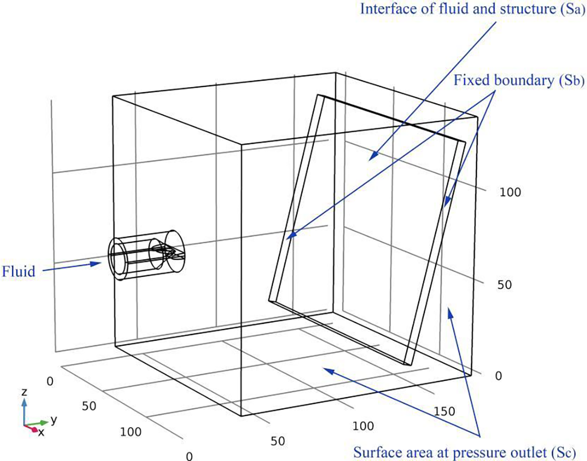
Figure 1: Schematic diagram of boundary conditions of high-pressure nozzle
In Fig. 1, Sa is the superficial areas of the fluid-structure (strike plate) interface, Sb is the fixed boundary, and Sc is the superficial areas of the pressure outlet.
By taking the pressure distribution of Eq. (3) into Eq. (6):
At the fluid-structure interface of the strike plate:
At the fix boundary of the strike plate:
And at the outlet of flow field:
where, n is the normal direction at the fluid-structure border,
Substituting Eqs. (8)–(10) into Eq. (7) [18]:
where, Ns is the insertion function vector.
The motion equation of the fluid can be discretized as follows:
where,
where, B is the matrix of coefficients;
2.2 Discrete Solid Structures Equations of Motion
The solid structure motion equation can be described as:
where, Ms is the displacement mass matrix of the structure, Cs is the damping matrix of the structure, Ks is the stiffness matrix of the structure,
The virtual work from the pressure at the fluid-structure interface is expressed as:
where,
The generalized force for general coordinates is:
where,
Assembled the force of each fluid element:
where,
By combining Eqs. (14) and (23), the motion equation of the fluid-structure system can be processed as Eq. (24):
A flat sector nozzle of the high-pressure water descent system at the inlet of the R1R2 roughing mill of the 2050 mm production line was selected to analyze the characteristics of the external flow field. The nozzle model was built, as shown in Fig. 2.
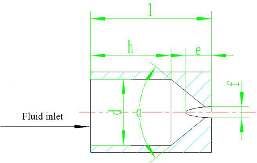
Figure 2: Schematic diagram of high-pressure water descaling nozzle
In Fig. 2, α is the inlet contraction angle of the inner cone hole (°), d is the inlet diameter (mm), l is the length of the nozzle (mm), h is the inner hole depth (mm), f is the cutting width of the U-shaped groove (mm), and e is the cutting depth of the U-shaped groove (mm).
The structural parameters of the descaling nozzle are shown in Table 1. The tetra grid was selected to dense the elliptical groove and the flow field contraction area inside the nozzle, as shown in Fig. 3.
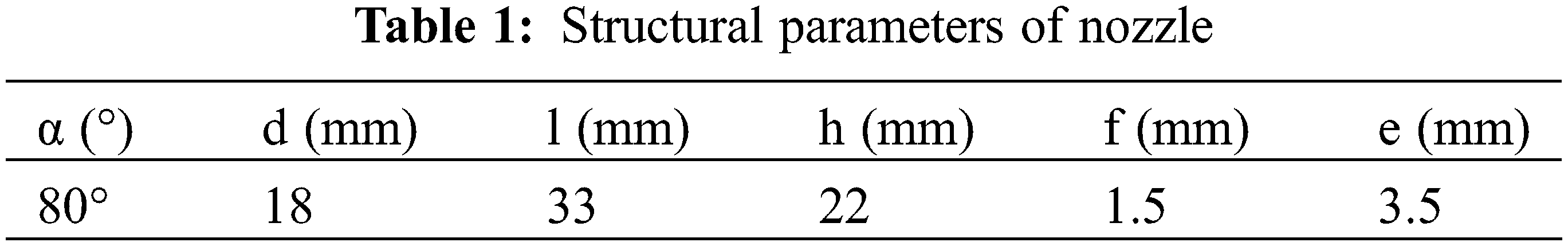
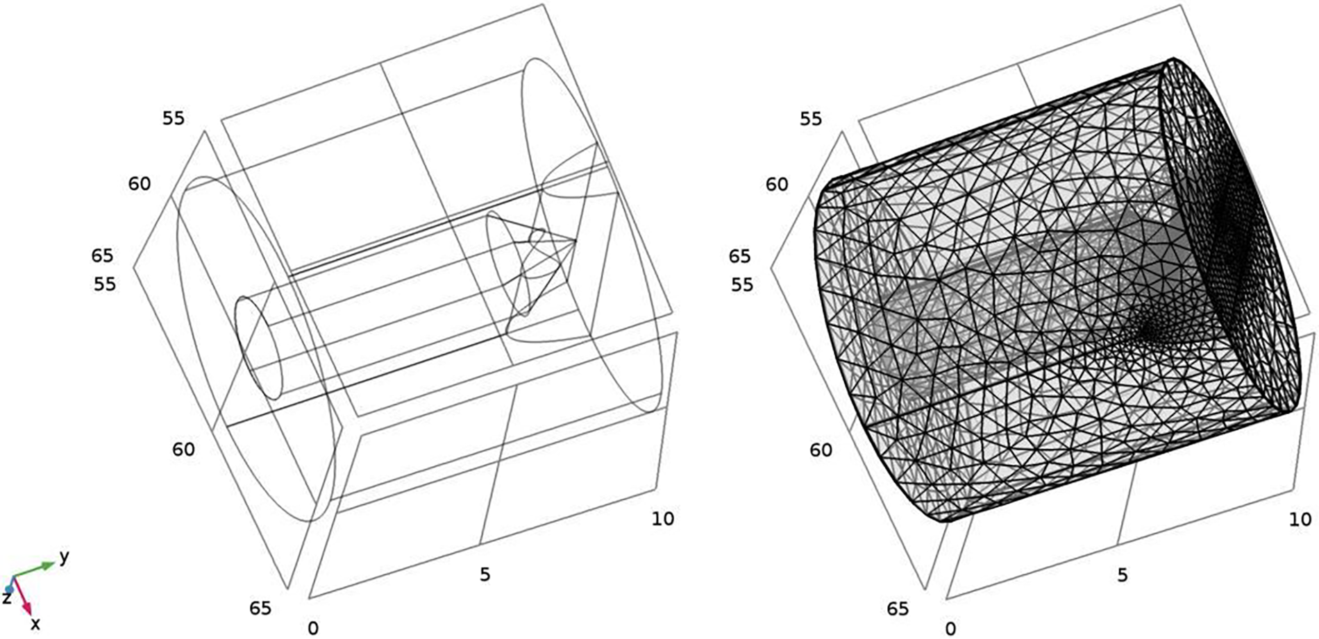
Figure 3: Structure and grid division of descaling nozzle
Referred to as the on-site situation, the external jet area was established with a side length of 140 mm in COMSOL Multiphysics, and the unstructured grid was densified at the junction of the nozzle and the external flow field. FSI module was selected as the calculation module, the mesh smoothing type was Winslow, inertia terms about the transient form of the structure were included. A steady-state solver with a relative tolerance of 0.001 was selected.
The pressure inlet (23 MPa) was used at the high-pressure water inlet (Fig. 1), and pressure outlets were placed on all sides of the fluid zone. A no-slip wall boundary condition was adopted on the wall in contact with the fluid, and the iterative staggered method was used.
4 Simulation Results and Comparison Verification
The velocity distribution of the external flow field was obtained by numerical calculation in COMSOL Multiphysics. In Fig. 4, sections XY and YZ were selected to observe the velocity distribution in the central axis of the nozzle in the external region.
Figure 4: Velocity distribution of external flow field on XY section and YZ section (m/s)
According to Fig. 4, the velocity on sections XY and YZ was symmetrical along the central axis of the nozzle, and the overall velocity gradually decreased with the increase in distance in the Y direction. In the central region of the jet, the maximum water flow velocity reached more than 200 m/s. With the increase in target distance in the Y direction, the water flow velocity decreased rapidly to 60 m/s at the 115 mm position in the Y direction. Furthermore, affected by the intersection of the shrinking area and the nozzle grooving area, the fan-shaped surface in the XZ plane had a larger velocity diffusion range than that in the YX plane. At the edge of the fan-shaped jet, the shear effect between the water flow and the air was evident, thereby reducing the water velocity to less than 40 m/s.
Fig. 5 shows the flow field velocity section in the XZ plane. The water jet was distributed in a flat shape in the XZ plane, which corresponded to the actual strike zone during descent. The four velocity sections were cut at equal intervals within a 200 mm distance along the Y axis. The velocity at the center of each section was the highest, and it was distributed in a flat form along the X-axis. The velocity decreased around the striking area, whereas the range of the strike increased with the distance of the Y axis.
Figure 5: Velocity distribution of external flow field on XZ section (m/s)
A target distance of 30 to 120 mm was selected from the nozzle along the Y-direction, and velocity data were extracted at the descaling strike line, as shown in Fig. 6. At the jet pressure of 23 MPa, the velocity distribution curves at the target distance of 30 to 120 mm were obtained. The jet velocity at different target distances obtained the 70 mm position of the X-axis as the symmetrical center. Moreover, the central area was more uniformly distributed in the X direction with the increase in the distance in the Y direction. As the water jet velocity exceeded the central area and reached the boundary zone, the velocity decreased evidently. The maximum velocity was approximately 230 m/s at the 30 mm target distance. The effective length of the central area in the X direction was 40 mm, the maximum velocity at the 60 mm target distance was approximately 130 m/s, the effective length of the central area in the X direction was 59 mm, and the effective length of the central area in the X direction was 81 mm. The central area was increased with the target distance along the X direction.
Figure 6: Distribution of velocity at different target distances along X direction
The simulated jet center length with target distances of 50, 70, 90, and 110 mm was in accordance with the experimental strike data in the nozzle parameter manual in Fig. 7, and it increased from 40 to 81 mm as the distance between the targets increased from 30 to 120 mm. The jet center length slowed down as the target distance increased.
Figure 7: Comparison of simulated jet center length and experimental strike length
The 30–140 mm velocity along the Y-axis at the jet center of the nozzle was extracted from Fig. 8. The velocity at the jet center decreased significantly with the increase in the target distance. At the distance of 30 mm between the near tip and the nozzle, the maximum velocity in the jet center reached approximately 180 m/s, whereas the maximum speed dropped to approximately 55 m/s at the distance of 140 mm from the far end to the nozzle. The reduction in the velocity of the high-pressure water jet was due to the air resistance in the external flow field. This finding was pronounced when the fluid jet was at a high speed, that is, the velocity of the first half section (30–70 mm) of the jet centerline along the Y-axis decreased at a faster rate than the last half section (70–140 mm).
Figure 8: Maximum velocity of jet center length at different target distances along the Y-axis
Three sprinklers with a spacing of 45 mm were introduced along the X-axis given the distribution shape of the on-site water collection beam sprinklers, and steel impact sample plates with specification of 140 mm × 140 mm × 4 mm were added for FSI analysis, as shown in Fig. 9.
Figure 9: FSI stress analysis of impact sample plate
Fig. 9 illustrates that the sample has been impacted with fluid at a target distance of 115 mm. In the XY section of the jet center line, the velocity decreased gradually with the increase in target distance and decreased to below 40 m/s with the conduction of the impact force at the location of the plate surface. The maximum equivalent stress on the surface of the plate along the jet center line was 10 MPa, and the minimum equivalent stress in the midpoint of the adjacent nozzles was approximately 4.5 MPa.
The impact sample plate test was performed in the rough rolling on the 2050 production line, as shown in Fig. 10. The plate had specification of 2 m × 1.5 m × 0.04 m and was set according to the conditions of the simulation. A 15 mm rusted slot intentionally left at the gap between the adjacent nozzles, which corresponded to the position of the minimum equivalent stress in Fig. 9.
Figure 10: Impact sample plate test on site
Fig. 11 shows the simulation data of the equivalent stress distribution over the surface of the impact sample plate. At the centerline of the jet, the maximum equivalent stress caused by the jet on the surface was approximately 10 MPa and reached 20 MPa at the fixed restraining boundary at both ends of the plate. The minimum impact force in the middle of the adjacent nozzles decreased to 4.5 MPa, primarily causing the rust slot shown in Fig. 10.
Figure 11: Equivalent stress distribution of impact sample surface (MPa)
The characteristics of the external flow field of the high-pressure descent nozzles and the descent effects of the impact plate descent were analyzed. This study demonstrated that the target distance directly affected the descaling effect when the descaling pressure and nozzle structure parameters were determined. The corresponding impact force increased with the kinetic energy provided by the fluid. The velocity distribution of different sections can be used as the basis for selecting the optimal target distance.
A non-uniform phenomenon was observed in the velocity distribution near the nozzle section at a target distance of 30 mm. This phenomenon cannot be eliminated because of the jet characteristics of the fan nozzle structures, and the uneven distribution of the strike force in this region affected the descaling process. However, as the target distance increased from 30 to 120 mm, the tendency for bifurcation in the central region decreased. Despite the decrease in strike force provided by the stable flow field, the expansion of the central area had a better descaling effect on the steel plate. Higher fluid velocities could be achieved when the target distance was close, but a smaller jet strike area, a non-uniform distribution of local strike force, and an increase in the number of descaling nozzles on the barrel could be observed, resulting in a waste of water resources. If the target distance was far, then the velocity of the water jet is insufficient to achieve the required descaling strike force.
In the FSI analysis of the three nozzle jets, the maximum equivalent stress on the plate surface along the center line of the jet was 10 MPa, and the minimum equivalent stress between the adjacent nozzles was 4.5 MPa. The position with the minimum equivalent stress was in good agreement with that of the rust slit in the impact sample plate test on site. The simulation model can express the impact position of the high-pressure water descaling nozzle on the plate, thereby providing calculation schemes for optimizing the nozzle space arrangement and improving the descaling effects of slabs with different rolling specifications.
Acknowledgement: None.
Funding Statement: The research was funded by Science and Technology Project of Hebei Education Department (Project Number: QN2022198). Y. C. received the grant.
Author Contributions: Study conception and design: Y. C., L. Y. W.; Data collection: L. Y. W., D. W.; Analysis and interpretation of results: Y. C., J. W.; Draft manuscript preparation: Y. C., H. S. L.
Availability of Data and Materials: All data and materials used to support the findings of this study are available from the corresponding author upon request.
Conflicts of Interest: The authors declare that they have no conflicts of interest to report regarding the present study.
References
1. Liu, L. (2022). Perceive the resilience of China’s economy-reduce the quantity and improve the quality-Innovate the efficiency of the steel industry-achieve new breakthroughs in quality. CCTV News. [Google Scholar]
2. Liang, B. J., Gao, D. R. (2018). Effects of structural parameters on the high-pressure water descaling nozzle performance. China Mechanical Engineering, 29(24), 2939–2946. [Google Scholar]
3. Huang, F. Z. (2013). Finite element simulation of plate high-pressure water descaling. Wuhan, China: Wuhan University of Science and Technology. [Google Scholar]
4. Giussani, F., Piscaglia, F., Saez-Mischlich, G. (2020). A three-phase VOF solver for the simulation of in-nozzle cavitation effects on liquid atomization. Journal of Computational Physics, 406(2), 109068. [Google Scholar]
5. Guha, A., Barron, R. M., Balachandar, R. (2011). An experimental and numerical study of water jet cleaning process. Journal of Materials Processing Technology, 211(4), 610–618. [Google Scholar]
6. Maniadaki, K., Kestis, T., Bilalis, N., Antoniadis, A. (2007). A finite element-based model for pure waterjet process simulation. International Journal of Advanced Manufacturing Technology, 31(9–10), 933–940. [Google Scholar]
7. Urazmetov, O., Cadet, M., Teutsch, R., Antonyuk, A. (2021). Investigation of the flow phenomena in high-pressure water jet nozzles. Chemical Engineering Research and Design, 165(14), 320–332. [Google Scholar]
8. Zhou, W. Y. (2016). Research of subway tunnel cleaning equipment structure and analysis of flat fan nozzle. Chengdu, China: Southwest Jiaotong University. [Google Scholar]
9. Qiao, W. T., Shao, X. Y., Qian, L. J., Lin, J., Liu, Y. Q. (2021). Numerical study on the optimization of atomization flow field in air nozzle using response surface methodology. Machine Tool & Hydraulics, 49(9), 149–157. [Google Scholar]
10. Liu, Q. Z., Li, H. X., Liu, Y. P. (2018). Research on flow field numerical simulation of ultrasonic nozzle with gas-liquid two phase coaxial type. Machine Tool & Hydraulics, 46(19), 122–124. [Google Scholar]
11. Chen, P. (2018). Analysis of influence of structure and parameters on performance of high-pressure water descaling nozzle and optimization. Qinhuangdao, China: Yanshan University. [Google Scholar]
12. Mieszala, M., Torrubia, P. L., Axinte, D. A. (2017). Erosion mechanisms during abrasive waterjet machining: Model microstructures and single particle experiments. Journal of Materials Processing Technology, 247(3), 92–102. [Google Scholar]
13. Foldyna, J., Klich, J., Hlaváček, P., Zeleňák, M., Ščučka, J. (2012). Erosion of metals by pulsating water jet. Tehnicki Vjesnik, 19(2), 381–386. [Google Scholar]
14. Tamura, Y., Ueoka, S., Kimura, Y., Kabeya, K. (2020). Influence of injection distance on water droplet behavior in high pressure descaling. ISIJ International, 60(1), 128–135. [Google Scholar]
15. Kartal, F., Gökkaya, H. (2015). Effect of abrasive water jet turning process parameters on surface roughness and material removal rate of AISI 1050 steel. Material Prufung, 57(9), 773–782. [Google Scholar]
16. Aydin, G., Kaya, S., Karakurt, I. (2019). Effect of abrasive type on marble cutting performance of abrasive water jet. Arabian Journal of Geosciences, 12(11), 1–8. [Google Scholar]
17. Kumar, K. R., Sreebalaji, V. S., Pridhar, T. (2018). Characterization and optimization of Abrasive Water Jet Machining parameters of aluminium/tungsten carbide composites. Measurement, 117(10), 57–66. [Google Scholar]
18. Zhang, A. M., Dai, S. S. (2011). Fluid structure coupling dynamics. Beijing, China: National Defense Industry Press. [Google Scholar]
Cite This Article
 Copyright © 2024 The Author(s). Published by Tech Science Press.
This work is licensed under a Creative Commons Attribution 4.0 International License , which permits unrestricted use, distribution, and reproduction in any medium, provided the original work is properly cited.
 Downloads
 Citation Tools