
 Submit a Paper
 Propose a Special lssue
 Open Access
ARTICLE
Experimental Study on Gas Flow Uniformity in a Diesel Particulate Filter Carrier
1
School of Energy and Power Engineering, Shandong University, Jinan, 250061, China
2
State Key Laboratory of Engines, Tianjin University, Tianjin, 300072, China
3
Weichai Power Emission Solutions Technology Company Limited, Weifang, 261043, China
4
China·Shandong·YYO Emission Control System Co., Ltd., Liaocheng, 252100, China
* Corresponding Authors: Ke Sun. Email: ; Guihua Wang. Email:
Fluid Dynamics & Materials Processing 2024, 20(1), 193-204. https://doi.org/10.32604/fdmp.2023.030561
Received 12 April 2023; Accepted 08 June 2023; Issue published 08 November 2023
 View Full Text
 Download PDF
Abstract
A Diesel Particulate Filter (DPF) is a critical device for diesel engine exhaust products treatment. When using active-regeneration purification methods, on the one hand, a spatially irregular gas flow can produce relatively high local temperatures, potentially resulting in damage to the carrier; On the other hand, the internal temperature field can also undergo significant changes contributing to increase this risk. This study explores the gas flow uniformity in a DPF carrier and the related temperature behavior under drop-to-idle (DTI) condition by means of bench tests. It is shown that the considered silicon carbide carrier exhibits good flow uniformity, with a temperature deviation of no more than 2% with respect to the same radius measurement point at the outlet during the regeneration stage. In the DTI test, the temperature is relatively high within r/2 near the outlet end, where the maximum temperature peak occurs, and the maximum radial temperature gradient is located between r/2 and the edge. Both these quantities grow as the soot load increases, thereby making the risk of carrier burnout greater. Finally, it is shown that the soot load limit of the silicon carbide DPF can be extended to 11 g/L, which reduces the frequency of active regeneration by approximately 40% compared to a cordierite DPF.Keywords
Diesel engine exhaust contains various air pollutants, which pollute the air and threaten the health of residents [1], so it must be controlled. With the continuous upgrading of emission laws and regulations, the requirements for particulate matter (PM) emissions are more stringent. While reducing PM emissions, there are also requirements for particulate numbers (PN) [2]. It is far from meeting the emission requirements only by taking internal purification measures. Meanwhile, the diesel particulate filter (DPF) aftertreatment technology is recognized as the most effective and technically mature measure to control PM emission [3–5].
The DPF generally adopts a wall-flow design structure, the main part of which is a cylindrical honeycomb ceramic cartridge, forcing the exhaust gas through the porous wall by blocking either end of the adjacent channel of the filter layer, and achieving the capture of particles by diffusion, inertial collision and gravitational deposition of particles and the interception of the cartridge. When the exhaust flows through the DPF, the particulate matter is captured through the hole wall in the DPF to purify the exhaust [6]. Particulate matter will accumulate continuously, and then the increase of exhaust back pressure will cause DPF blockage, and the engine power performance and fuel economy will deteriorate. Therefore, the particles captured by DPF need to be removed regularly to regenerate DPF [7–8]. When regenerating DPF, its internal temperature needs to be controlled within the conditions that make the support and catalyst reliable and effective, to achieve safe and reliable regeneration [9]. However, in the actual application process, the DTI phenomenon may occur during regeneration. At this time, due to the reduction of exhaust flow, the heat released by DPF regeneration cannot be taken away in time, resulting in a sharp increase in internal temperature, which may lead to carrier burning and melting [10]. To ensure the safety of the DPF regeneration, it is particularly important to control its temperature.
The gas flow uniformity of DPF carriers affects engine dynamics and economy, and many scholars have conducted research in this area [11–13]. Yunji et al. [14] applied fluent software to investigate the effect of exhaust gas incoming flow parameters and component variations on flow uniformity. Han et al. [15] used CFD simulations to obtain the geometry of the cartridge with the lowest pressure drop and the highest flow uniformity. Nicholas et al. [16] studied the airflow in DPF using magnetic resonance (MR) imaging and used the MR results to quantify the uniformity of the airflow through the filter wall. The DPF works in harsh environments and requires high-temperature resistance of the material, and there has been no shortage of research on high temperature resistance and safe regeneration in the development of DPF technology. Hamid et al. [17] have developed a DPF consisting of nanomaterials that can withstand drastic temperature field changes under uncontrolled regeneration. Li et al. [18] found that during the regeneration of cordierite DPF, the highest internal combustion temperature and maximum temperature rise rate were higher than those of silicon carbide DPF, resulting in a greater risk of burning loss. Hao et al. [19] divided the DPF regeneration into three stages and controlled the DPF regeneration temperature by changing the fuel injection rate before the diesel oxidation catalyst (DOC). Huang et al. [20] obtained the safe regeneration temperature curve through tests and optimized the control of regeneration temperature by considering the influence of exhaust temperature and exhaust flow. Chen et al. [21] compared the filtration efficiency when DTI occurred under different soot loads and regeneration temperatures. Fox et al. [22] conducted tests with DPF of the exact specification used in the actual vehicle and found that the back pressure could not fully reflect the regeneration effect because the back pressure may be reduced, and the DPF may still retain a significant ash level. Lee et al. [23] found that improving the pore structure can improve the DPF regeneration rate and broaden the soot load limit. Ran et al. [24] conducted simulation analysis on DPF regeneration through numerical simulation and found that there was a local high temperature in the central area of porous media, and the thermal stress was relatively concentrated, which was prone to thermal damage. Tan et al. [25] studied the temperature characteristics of regeneration under DTI working conditions based on experiments, and established a model that can predict peak temperature and maximum temperature gradient based on experimental data.
The DPF regeneration process requires a DPF carrier material with a high-temperature resistance to ensure reliable regeneration of the DPF. In this study, a silicon carbide carrier was used to study the gas flow uniformity of the carrier during the active regeneration of the DPF. A DTI approach was adopted to study its tolerance to the drastic changes in the temperature field inside the DPF. The limit soot load of the silicon carbide carrier is also broadened, and the results can be used as a reference for the study of the safety of DPF regeneration.
A 4-cylinder inline water-cooled diesel engine with a displacement of 2.3 L was used in this study. See Table 1 for specific engine parameters and Fig. 1 for the test bench layout.
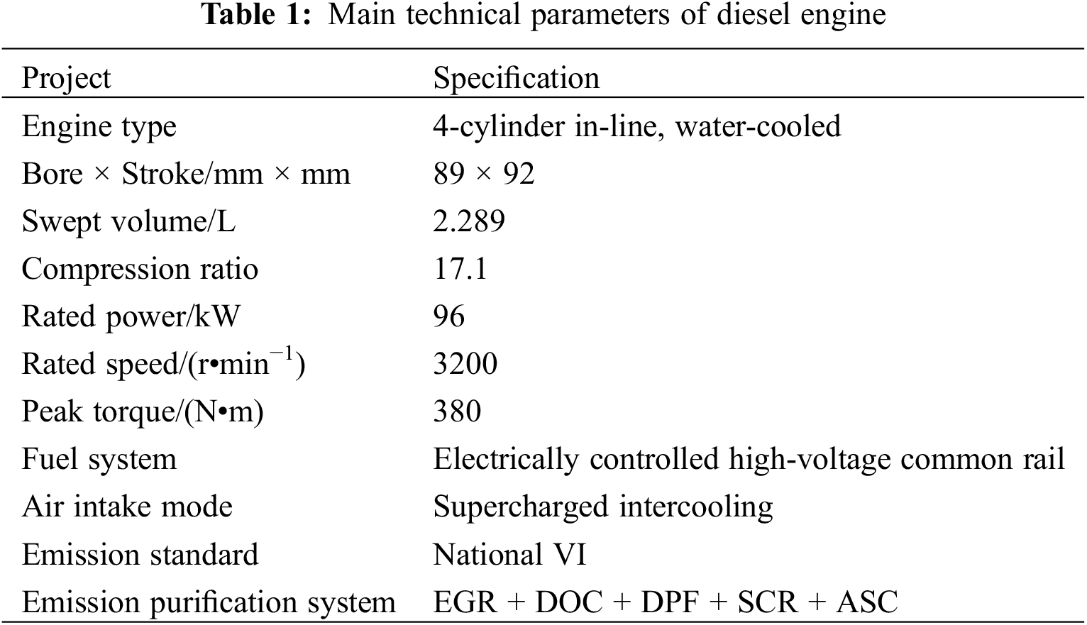
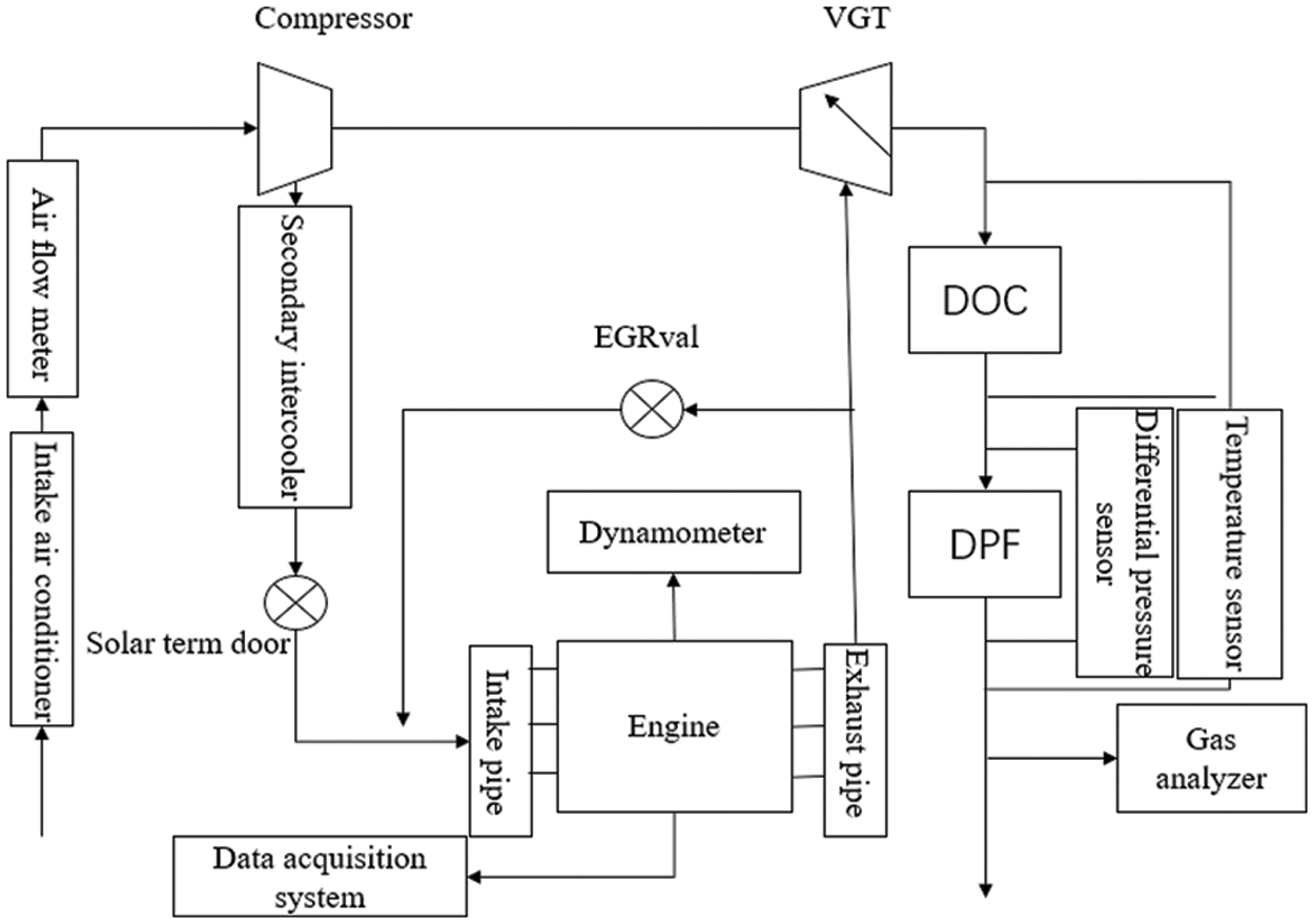
Figure 1: Layout of test bench
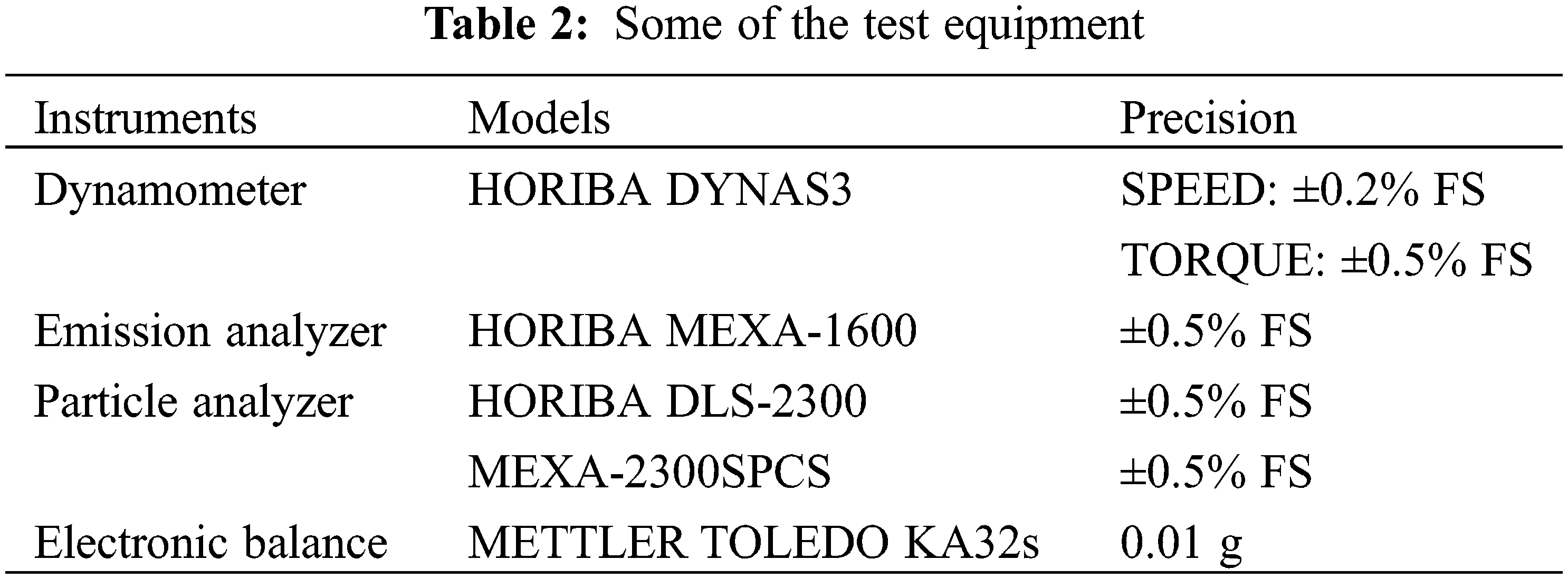
The test is controlled by the HORIBA engine measurement and control system. HORIBA DYNAS3 AC dynamometer is used to measure speed and torque, and the AVL735 fuel consumption meter is used to measure fuel consumption. HORIBA MEXA-1600 exhaust analyzer is used to analyze exhaust gas composition concentration. HORIBA DLS-2300 is used to measure PM, and MEXA-2300SPCS is used to measure PN for the study of particulate matter. The soot load of DPF was measured by METTLER TOLEDO KA32s precision balance. Some of the test equipment components are shown in Table 2.
As this paper focuses on PM and fuel consumption, the aftertreatment system is composed of DOC and DPF. See Table 3 for specific characteristic parameters. Temperature sensors are arranged at the inlet and outlet of DOC to monitor the temperature change in real time. Differential pressure sensors are placed at both ends of DPF to watch the evolution of exhaust back pressure in real time. The DPF gas flow uniformity test requires selecting 12 measuring points at a distance of 15 mm from the DPF outlet end and measuring the temperature data during regeneration using a K-type armored thermocouple. The selection of measuring points is shown in Fig. 2. To monitor the temperature field change in the DPF in real time in the DTI test, 15 measuring points were selected in the DPF, and the temperature was measured by K-type armored thermocouple. The distribution mode is shown in Fig. 3.
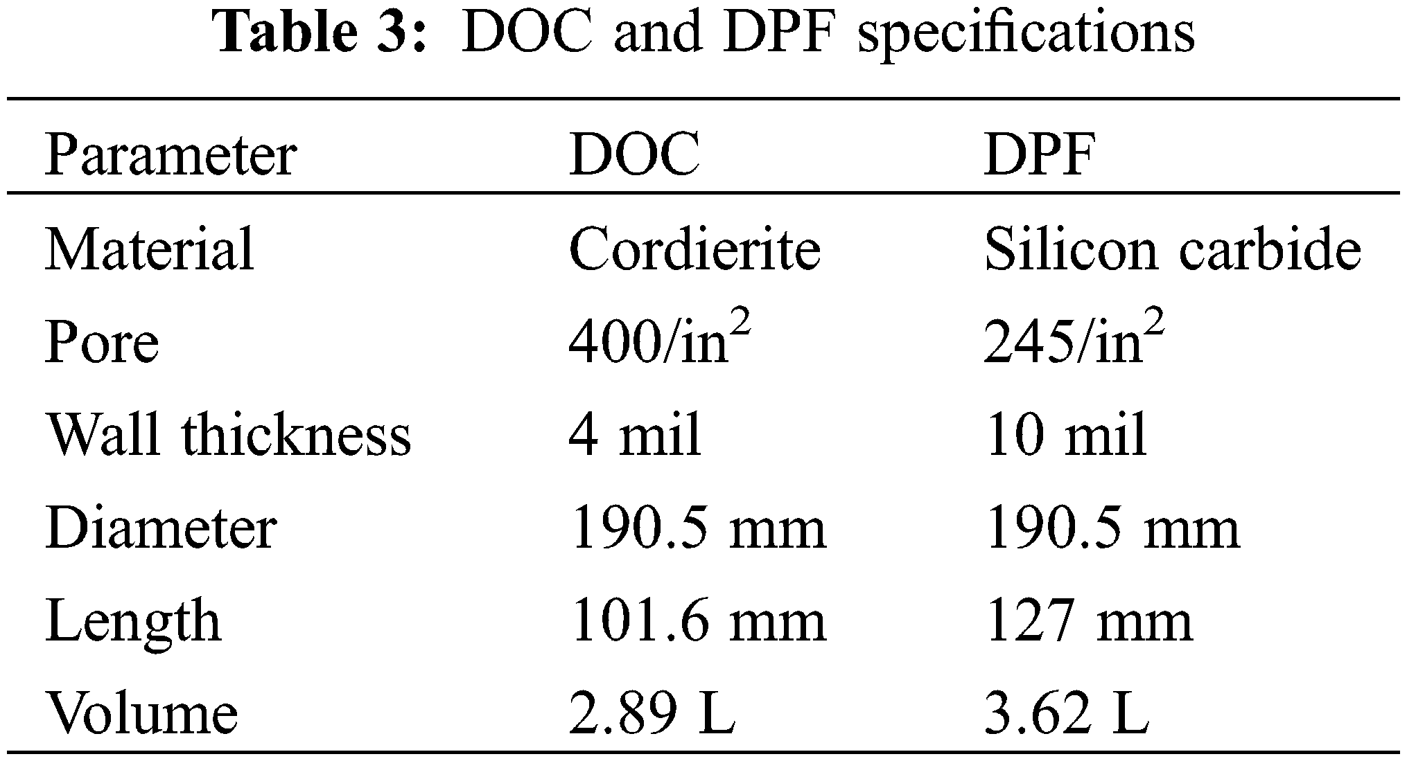
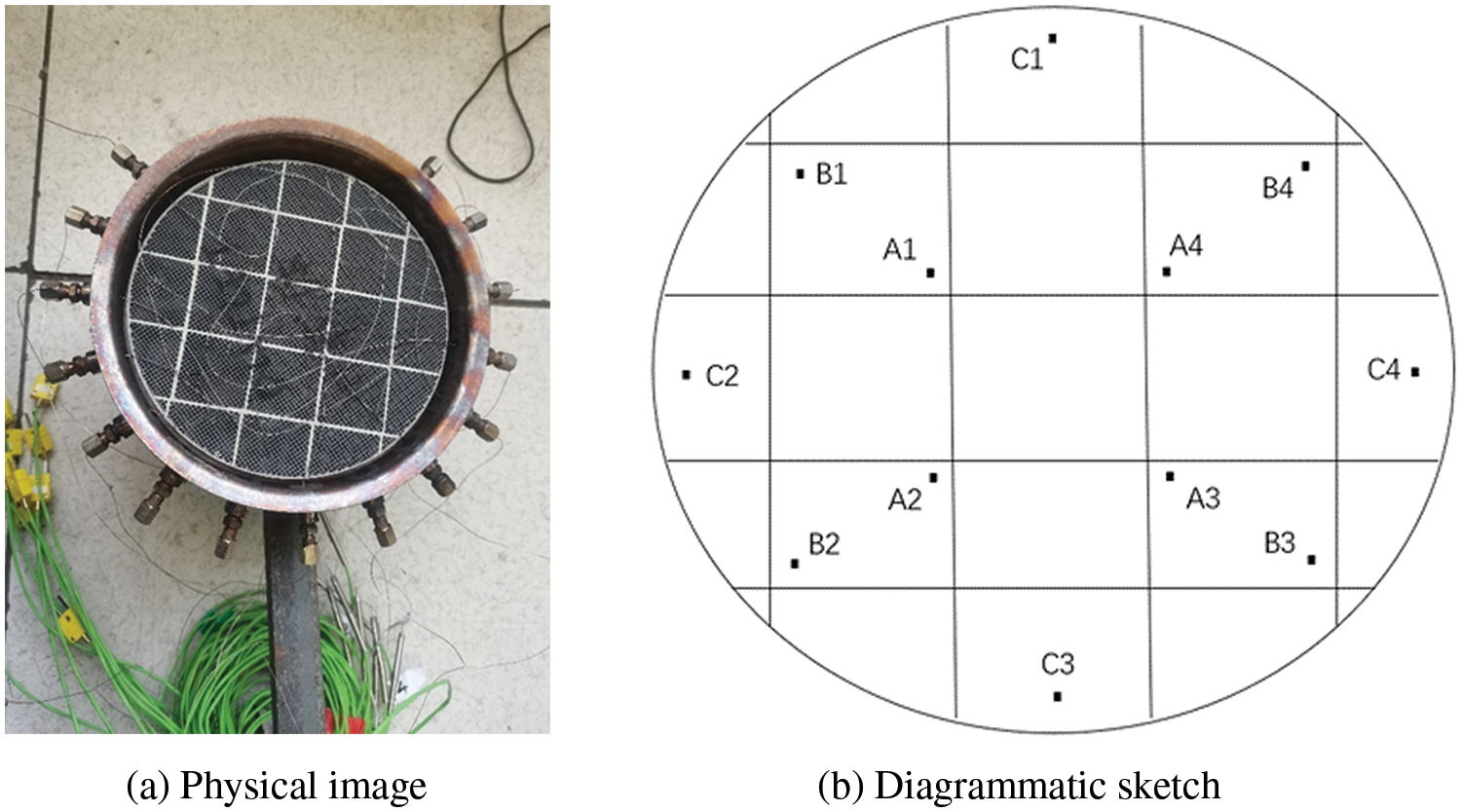
Figure 2: Distribution of temperature measurement points for flow uniformity testing
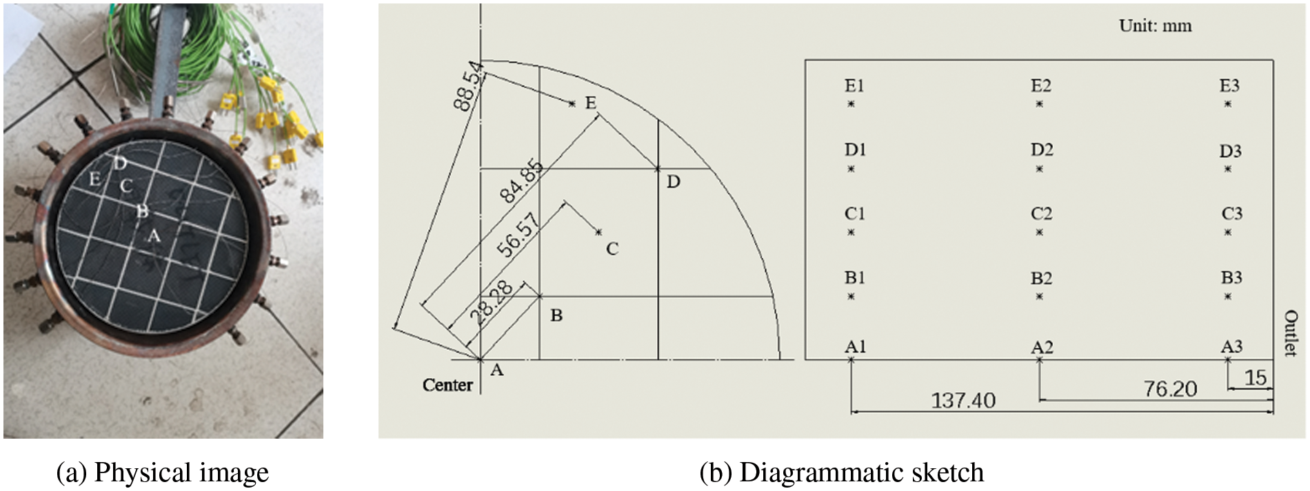
Figure 3: Distribution of DPF temperature field measurement points under DTI test
This study requires soot accumulation tests at soot load levels of 4, 8, 9, 10, and 11 g/L. The test flow is shown in Fig. 4.
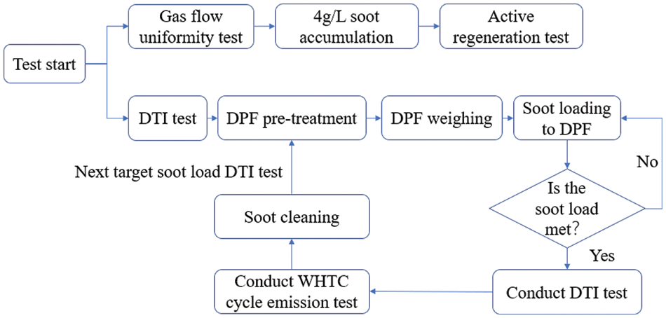
Figure 4: Test flow
Before each weighing of the DPF, pre-treatment of the DPF is carried out by the requirements of HJ 451-2008 “Technical Requirements for Environmental Protection Products-Diesel Vehicle Aftertreatment Device”. After preheating, the DPF can be weighed. Using the first 600 s of the WHTC (Worldwide Harmonized Transient Cycle) test cycle for soot accumulation, the exhaust temperature is between 473.15 and 573.15 K for a long time, which can shorten the soot accumulation cycle. The gas flow uniformity of the carrier is demonstrated by the temperature uniformity at the outlet during regeneration. A soot accumulation test with a 4 g/L soot load is required first, followed by active regeneration of the DPF. The regeneration working point is 2000 r/min and 200 N•m, and the temperature change at the outlet during the regeneration process is recorded. In the DTI test, the active regeneration was triggered at 2000 r/min and 60 N•m working point, and the unreacted HC was generated through the post-injection in the cylinder into the DOC for oxidative exotherm, bringing the DOC outlet temperature to 873.15 K. Once it is found that the DOC outlet temperature reaches the target value, immediately adjust the working point to 800 r/min, 0 N•m and stop the post-injection. During the test, the DPF internal temperature field data shall be collected until the temperature at all measuring points starts to decline.
After each DTI test, remove the DPF and check for deformation or cracking. If there is no damage to the DPF, install the DPF for WHTC cycle emission testing, and further determine whether the DPF is intact based on the emission results. If the DPF is not damaged, soot cleaning should be done on the DPF at a working point of 2000 r/min and 200 N•m. Maintain this working point for 40 min to ensure that the accumulated particles in the DPF are burned clean. Afterward, weigh and conduct the DTI test for the next target soot load. Through the emission results, it was found that the DPF was not damaged during this study.
3.1 Analysis of Carrier Gas Flow Uniformity
Fig. 5 shows the temperature variation at the outlet during active regeneration at a soot load of 4 g/L. From the Fig. 5, it can be seen that after the active regeneration starts, the outlet temperature of the DPF begins to rise rapidly, and the maximum temperature at the Class A measuring point exceeds 973.15 K. During the regeneration period, the temperature remains between 873.15 and 973.15 K. At the same time, the maximum temperature deviations A-TDmax, B-TDmax, and C-TDmax between various measuring points are shown in the Fig. 5. As the DPF temperature increases, there will be peaks in the maximum temperature deviation between various measuring points, with C-TDmax being the largest. This is because C-type measuring points are the farthest from the axis and the farthest from each other, resulting in a large temperature deviation. After 800 s, the temperature has begun to stabilize. The maximum temperature deviation between measuring points of the same radius is: the temperature deviation between A1 and A4 in Class A measuring points is 0.64%, the temperature deviation between B1 and B3 in Class B measuring points is 0.59%, and the temperature deviation between C1 and C4 in Class C measuring points is 1.8%. Satisfying the criterion of maximum temperature deviation ≤2% proves good temperature uniformity. This indicates that the uniformity of gas flow inside the carrier is good, so during the soot accumulation test, the capture effect of particles at the same radius position is similar, and the captured particles will not exhibit uneven distribution along the circumferential direction. The experimental results also indicate that the gas flow is uniform during the regeneration process, resulting in good heat dissipation and no high local temperatures.
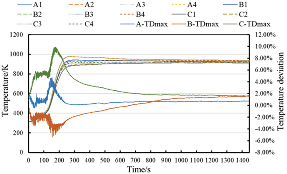
Figure 5: DPF outlet temperature variation during active regeneration at 4 g/L soot load
3.2 Analysis of Temperature Field in DTI Process
Fig. 6 shows the carrier’s temperature variation during the DTI test under different soot loads. At the required working point of 2000 r/min and 60 N•m, the DPF temperature rose from less than 473.15 K to between 573.15 and 673.15 K, and then remained stable. After specific thermal management, the active regeneration started, and unburned HC flowed into DOC for oxidation and generated heat. The heat carried by exhaust gas increased the DPF temperature, reaching the ignition temperature of the soot, and the soot started to burn. Since the heat released by oxidation will be transferred downstream, the DPF temperature downstream will be higher than that of upstream. With the intensification of oxidation, rapid heat release will accelerate the temperature increase. The intense oxidation started at the central position.
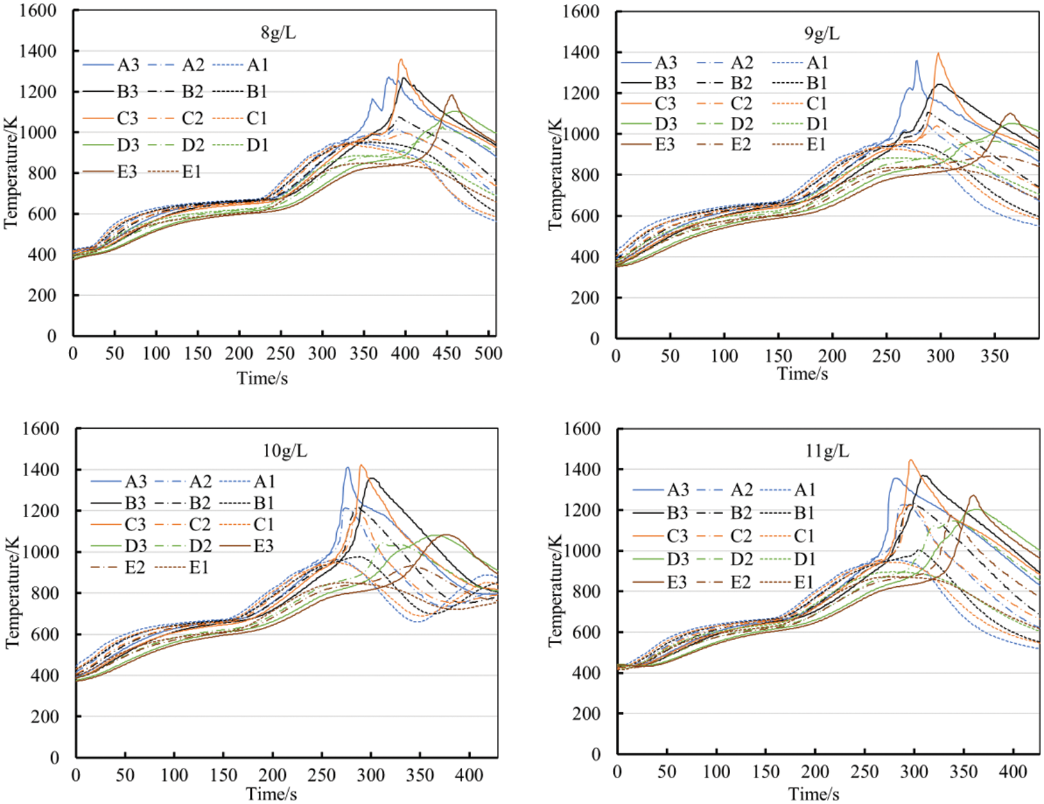
Figure 6: Temperature variation in the carrier during DTI under different soot loads
At A3 with 8 g/L, it can be seen that with the intensification of oxidation, the first temperature peak appeared. After the intense oxidation, if the exhaust flow rate remains constant, the temperature of DPF will generally decrease, as the heat carried away by the exhaust flow and other heat conduction will surpass the decreasing heat generation. However, at DTI condition, the engine speed will suddenly drop to idle state, drastically reducing the exhaust flow the heat generated by particulate oxidation cannot be taken away in time, and the heat from the upstream is taken to the downstream. Due to the uneven distribution of soot accumulation, more heat is generated from the area around the center of the DPF carrier or points B and C of Fig. 3. The temperature rose sharply, especially downstream, and the temperature peak of 1353.55 K appeared at C3. Subsequently, the temperature dropped. After heat conduction started the oxidation of the accumulated soot, the temperature toward the edge (points D and E) began to rise rapidly, reaching the peak and then decreasing. The thermocouple was damaged at measuring point E2 in the 8 g/L test and measuring point D1 in the 10 g/L test, which showed the possibility of uneven accumulation around the edge. Still, the temperature at the border was not high, which did not affect the analysis of the test results.
With the increase of soot load, the peak temperature showed an increasing trend, and all appeared at the position of C3. At 9, 10 and 11 g/L, the peak temperature reached 1383.35, 1411.65 and 1436.25 K, respectively. At 8 g/L, only the peak value of the C3 position exceeded 1273.15 K, while with the increase of soot load, A3, B3 and C3 positions all exceeded 1273.15 K at 11 g/L, and the temperature of the whole carrier increased. The temperature within r/2 was high, and the peak occurred near the outlet. The risk of carrier burning increased significantly as the soot load increased.
Fig. 7 shows the axial temperature gradient during the DTI test under different soot loads. Because the oxidation heat transferred inevitably downstream, the temperature downstream was observably higher than upstream, creating temperature gradients within DPF. The maximum axial temperature gradients at 8, 9, 10 and 11 g/L were 60.47, 58.99, 46.29 and 55.72 K/cm, which appeared at C3-C2, C3-C2, C2-C1 and E2-E1, respectively. The axial temperature gradients were generally acceptable, while the positions showed little regularity due to the uneven distribution. Besides, the gradient was barely affected by soot load at regeneration. And the phenomenon of carrier burning due to very uneven oxidation will not occur.
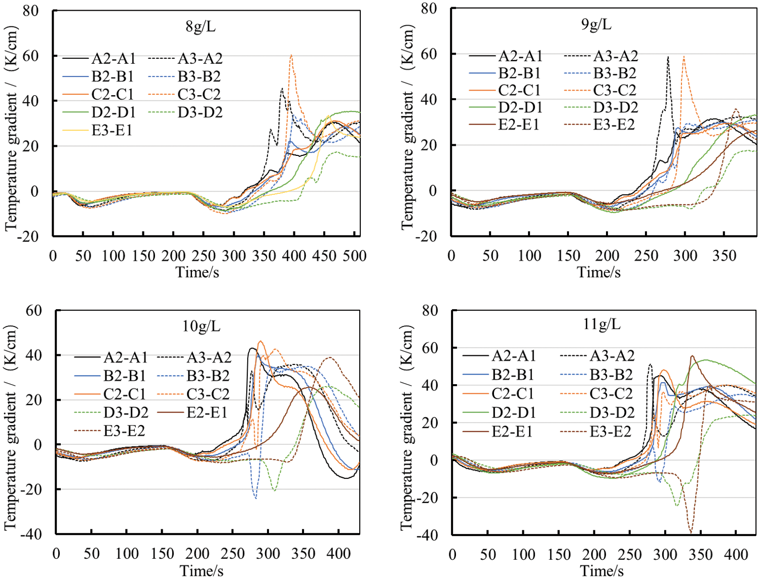
Figure 7: Internal axial temperature gradient under different soot loads
Fig. 8 shows the radial temperature gradient during the DTI test under different soot loads. The maximum radial temperature gradients at 8, 9, 10 and 11 g/L are 170.05, 191.51, 203.57 and 221.83 K/cm, respectively, which all appeared at D3-C3. Due to the uneven distribution of soot in the DPF, the radial heat generation was more uneven than the axial, and the intense oxidation towards the center occurred earlier than towards the edge. After the temperature peak shown in Fig. 6, the heat carried away will surpass the decreasing heat generation. However, this temperature decrease occurred earlier towards the center than the edge. This results in the maximum temperature gradient occurred at the area toward the edge, between points C and D. Compared to the axial temperature gradient, the radial temperature gradient was much larger, and increased significantly as the soot load increased. The risk of DPF carrier damage needs to be paid more attention to.
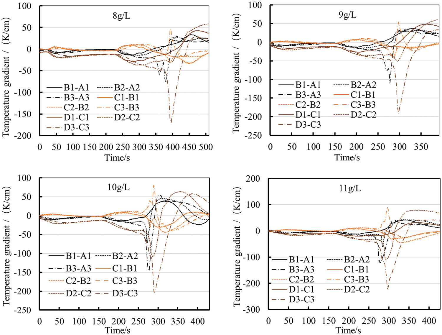
Figure 8: Internal radial temperature gradient under different soot loads
3.3 Analysis of Emission Results before and after DTI Test
In order to further determine whether the carrier is intact after the DTI test, WHTC emission tests has been conducted. The test results are shown in Table 4. The cycle emission results before soot accumulation are relatively higher than those after. The emission test results show that the carrier is not damaged in the four DTI tests. The analysis is that before the first test, the DPF was relatively clean, and the particles were easy to pass through, so the filtration effect was poor. With the accumulation of particles in the DPF, the pores become congested, and the trapping capacity improves.
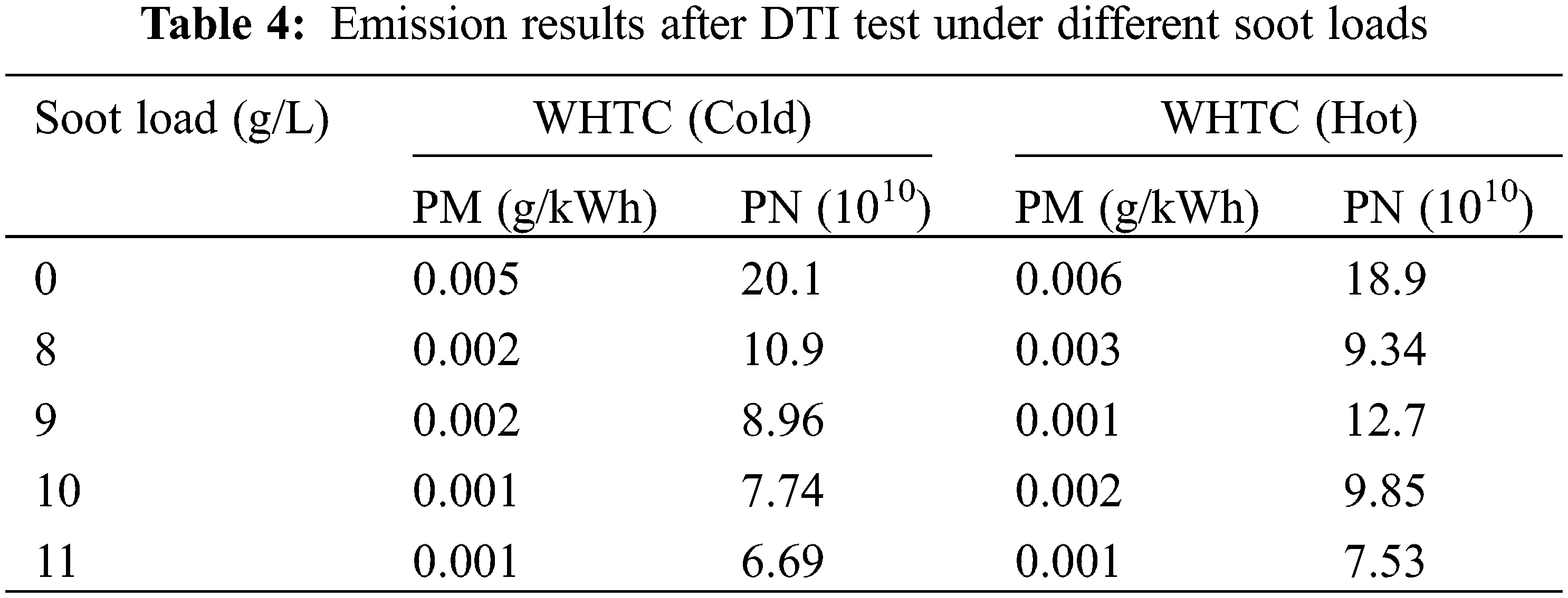
Chen et al. [21] only carried out DTI test under 8, 10 and 12 g/L soot load. The carrier of the 12 g/L soot load was burnt, but the carrier of the 8 and 10 g/L was not damaged. They did not consider the situation of the 11 g/L soot load. Through this study, it can be determined that the soot load limit of silicon carbide DPF can be expanded to about 11 g/L.
4 Discussion on the Advantages of Silicon Carbide DPF Compared to Cordierite DPF
There are two commonly used materials for DPF: cordierite and silicon carbide [26]. Silicon carbide has a higher cost than cordierite, but its performance has significant advantages compared to cordierite. Silicon carbide has better temperature resistance and can withstand higher temperatures than cordierite without causing structural damage. In the practical application of DPF, frequent regeneration is required. During the regeneration period, due to the oxidation and heat release of particles inside the DPF, the internal temperature of the DPF will rise, which may exceed the heat resistance limit of the material. This issue is particularly prominent in DTI experimental research. During active regeneration, a sudden drop in speed to idle will result in higher temperature peaks and more significant temperature gradients inside the DPF, and there will be an increasing trend as the soot load increases. When the soot load of cordierite DPF accumulates to around 5 g/L, regeneration is necessary. Otherwise, there is a risk of burning loss [27]. In contrast, the silicon carbide DPF used in this study was still intact at a soot load of 11 g/L when DTI occurred, which is more than twice that of cordierite DPF, showing that silicon carbide DPF has better safety properties.
This paper discusses the advantages of a silicon carbide DPF more specifically, considering the actual operating characteristics of the engine in this experiment. The test cycle program was simulated considering the actual working conditions of this engine, and the soot accumulation results of the DPF are shown in Fig. 9, which shows that the running time increases linearly with the soot load. If loaded with cordierite DPF, regeneration is required after approximately 18 h, while switching to silicon carbide DPF reduces active regeneration frequency to approximately 40%. The duration of active regeneration will not change significantly due to the increase in soot load, and the difference in fuel consumption required for a single active regeneration is not significant. The safety soot load limit of silicon carbide DPF is high, so in practical applications, silicon carbide DPF can accumulate more soot. Compared to cordierite DPF, it does not need to be regenerated so frequently. The required regeneration mileage is long, reducing the accumulated fuel consumption during regeneration and improving fuel economy.
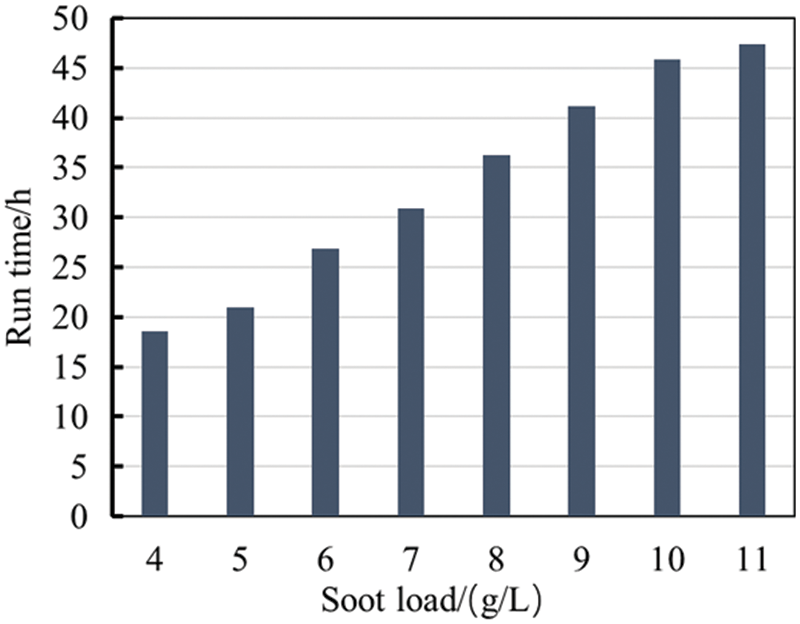
Figure 9: Engine running time required for different soot loads
1. The silicon carbide carrier shows good gas flow uniformity with no more than 2% temperature deviation from the same radius measurement point at the outlet end during active regeneration of the DPF.
2. A sharp drop in DPF active regeneration to idle speed results in that the temperature is relatively high within r/2 near the outlet end, where the maximum temperature peak occurs, and the maximum radial temperature gradient occurs from r/2 to the edge. And they both increase as the soot load increases, making the risk of carrier burnout greater. When DTI occurs at 11 g/L soot load, a peak temperature of 1436.25 K and a temperature gradient of 221.83 K/cm are reached, while the silicon carbide carrier remains intact and shows good resistance to high temperatures.
3. Silicon carbide carriers show better tolerance than cordierite carriers to the dramatic temperature field changes under DTI conditions. The soot load limit of silicon carbide DPF can be extended to 11 g/L, more than twice that of cordierite. By increasing the soot load limit to 11 g/L, the active regeneration frequency of the silicon carbide DPF is reduced by approximately 40%.
Acknowledgement: The authors want to show sincere thanks to all the techniques who have helped this research and all the authors of the references.
Funding Statement: This work was supported by National Key R&D Program Project [Grant Number 2020YFB0106603], Provincial Major Scientific and Technological Innovation Project [Grant Number 2021CXGC010207-1], Shantui Engineering Machinery Intelligent Equipment Innovation and Entrepreneurship Community Innovation Project [Grant Number GTT2021105], Shandong Provincial Science and Technology SMEs Innovation Capacity Improvement Project [Grant Numbers 2021TSGC1334], and Undergraduate School of Shandong University, China [Grant Number 2022Y155].
Author Contributions: The authors confirm contribution to the paper as follows: study conception and design: Guihua Wang, Ke Sun, Shuzhan Bai; data collection: Jianhua Zhang, Guoliang Su; analysis and interpretation of results: Peixing Yang, Xiantao Fan; draft manuscript preparation: Zhengyong Wang. All authors reviewed the results and approved the final version of the manuscript.
Availability of Data and Materials: The specific data involved in this study cannot be published due to the relevant non-disclosure agreement. If any readers need more information, please contact the corresponding author’s email.
Conflicts of Interest: The authors declare that they have no conflicts of interest to report regarding the present study.
References
1. Boger, T., Rose, D., Tilgner, I., Heibel, A. (2009). Regeneration strategies for an enhanced thermal management of oxide diesel particulate filters. SAE International Journal of Fuels and Lubricants, 1(1), 162–172. [Google Scholar]
2. Liu, X., Wang, Z., Li, Y., Liu, Q. (2021). Research on emission standards and control technology of heavy commercial diesel vehicles. IOP Conference Series: Earth and Environmental Science, 687, 012030. [Google Scholar]
3. Koji, T., Kazuhiro, Y. (2012). A study on the cell structure and the performances of wall-flow diesel particulate filter. Energy, 48(1), 492–499. [Google Scholar]
4. Meng, Z., Li, J., Fang, J., Tan, J., Qin, Y. et al. (2020). Experimental study on regeneration performance and particle emission characteristics of DPF with different inlet transition sections lengths. Fuel, 262(15), 116487. [Google Scholar]
5. Joshi, A. (2020). Review of vehicle engine efficiency and emissions. SAE International Journal of Advances and Current Practices in Mobility, 2(5), 2479–2507. [Google Scholar]
6. Bensaid, S. (2009). Modelling of diesel particulate filtration in wall-flow traps. Chemical Engineering Journal, 154(1), 211–218. [Google Scholar]
7. Theinnoi, K., Gill, S. S., Tsolakis, A., York, A. P. E., Megaritis, A. et al. (2012). Diesel particulate filter regeneration strategies: Study of hydrogen addition on biodiesel fuelled engines. Energy & Fuels, 26(2), 1192–1201. [Google Scholar]
8. Meng, Z., Zeng, B., Tan, J., Chen, Z., Ou, J. (2022). Study of gas and particulate emission characteristics during the fast regeneration period of DPF. Fuel, 317(16), 123353. [Google Scholar]
9. Shankar, R., Chauhan, A., Krishnan, N., Vasudevan, C. (2021). Investigation of temperature distribution inside the diesel particulate filter (DPF) during the drop to idle test (DTIT) performed at steady-state and worst-case driving cycles. SAE International Journal of Advances and Current Practices in Mobility, 4(1), 191–197. [Google Scholar]
10. Recker, P., Pischinger, S. (2012). Thermal shock protection for diesel particulate filters. SAE International Journal of Engines, 5(2), 112–118. [Google Scholar]
11. Yang, S., Deng, C., Gao, Y., He, Y. (2016). Diesel particulate filter design simulation: A review. Advances in Mechanical Engineering, 8(3), 1–14. [Google Scholar]
12. Nakamura, K., Konstandopoulos, A., Kostoglou, M., Shibata, T., Hashizume, Y. (2014). New asymmetric plugging layout of diesel particulate filters for the pressure drop reduction. SAE Technical Paper. 2014-01-1512. [Google Scholar]
13. Bin, G., Reggie, Z., He, L., Zhen, H. (2015). Review of the state-of-the-art of exhaust particulate filter technology in internal combustion engines. Journal of Environmental Management, 154, 225–258. [Google Scholar]
14. Yunji, K., Danbee, H., Seo, T., Oh, K., Baek, Y. et al. (2020). Effect of particulate matter and ash amount on pressure drop and flow uniformity of diesel particulate filter reduction system. Clean Technology, 26(1), 22–29. [Google Scholar]
15. Han, D., Hyunseung, B., Baek, Y. (2020). CFD analysis on effect of pressure drop and flow uniformity with geometry in 13″ asymmetric DPF. Transctions of the Korean Hydrogen and New Energy Society, 31(6), 614–621. [Google Scholar]
16. Nicholas, P. R., Andrew, P. E., Andrew, J. S., Lynn, F. G. (2017). Magnetic resonance velocity imaging of gas flow in a diesel particulate filter. Chemical Engineering Science, 158, 490–499. [Google Scholar]
17. Hamid, C., Borghei, A. M., Porshokoohi, M. G. (2021). Nano-ceramic filter for trapping diesel particles. Russian Agricultural Sciences, 47(3), 296–303. [Google Scholar]
18. Li, Q., Lv, Y., Chen, G., Peng, Y., Lai, Y. et al. (2020). Passive regeneration characteristics of different materials CDPF at high temperature limit. Chinese Society for Internal Combustion Engines, 38(6), 505–513. [Google Scholar]
19. Sun, H., Liu, Y. S., Li, N., Tan, J. W. (2022). Study on characteristics and control strategy of diesel particulate filters based on engine bench. Processes, 10(7), 1246. [Google Scholar]
20. Huang, T., Hu, G., Guo, F., Yang, M., Zhu, Y. et al. (2020). Temperature control experiment of DPF during thermal regeneration. Chinese Society for Internal Combustion Engines, 38(3), 257–264. [Google Scholar]
21. Chen, P., Zhu, L., Liu, D., Pan, X., Ceng, W. et al. (2021). Test of temperature field distribution and analysis of filtration efficiency during DPF drop to idle regeneration. Chinese Society for Internal Combustion Engines, 39(2), 159–166. [Google Scholar]
22. Fox, J. T., Yang, K., Hunsicker, R. (2020). Diesel particulate filter cleaning effectiveness: Estimated ash loading, quantified particulate removal, and post-cleaning filter pressure drop. Emission Control Science and Technology, 6(1), 75–85. [Google Scholar]
23. Lee, K., Kim, S., Kwang, C. O. (2021). The effect of pore structure on thermal characteristics of a cordierite diesel particulate filter for heavy duty diesel vehicle. International Journal of Automotive Technology, 22(1), 243–251. [Google Scholar]
24. Gao, R., Tong, C. Z., You, H., Zhou, X. R., Huang, X. D. et al. (2022). Research on regeneration characteristics of diesel particulate filter based on fluid-thermal-solid coupling. Process Safety and Environmental Protection, 163(3), 298–307. [Google Scholar]
25. Tan, P., Duan, L., Li, E., Hu, Z., Lou, D. (2020). Experimental study on the temperature characteristics of a diesel particulate filter during a drop to idle active regeneration process. Applied Thermal Engineering, 178(2), 115628. [Google Scholar]
26. Firat, M., Coskun, N. Y., Okcu, M., Varol, Y. (2019). Numerical investigation of regeneration process of diesel particulate filter (DPF) made of different constitutive materials. Journal of the Faculty of Engineering and Architecture of Gazi University, 34(1), 297–308. [Google Scholar]
27. Federico, M., Maurizio, A., Mahsa, R., Davide, M., Chiara, P. (2015). Impact on vehicle fuel economy of the soot loading on diesel particulate filters made of different substrate materials. Energy, 86(2), 19–30. [Google Scholar]
Cite This Article
 Copyright © 2024 The Author(s). Published by Tech Science Press.
This work is licensed under a Creative Commons Attribution 4.0 International License , which permits unrestricted use, distribution, and reproduction in any medium, provided the original work is properly cited.
 Downloads
 Citation Tools