
 Submit a Paper
 Propose a Special lssue
 Open Access
REVIEW

Flow Regimes in Bubble Columns with and without Internals: A Review
1 Department of Chemical Engineering, University of Technology-Iraq, Baghdad, Iraq
2 Chemical and Petroleum Industries Engineering Department, Al-Mustaqbal University College, Babylon, Iraq
3 Department of Chemical and Biochemical Engineering, Missouri University of Science and Technology, Rolla, USA
* Corresponding Author: Laith S. Sabri. Email:
(This article belongs to the Special Issue: Recent advancements in thermal fluid flow applications)
Fluid Dynamics & Materials Processing 2024, 20(2), 239-256. https://doi.org/10.32604/fdmp.2023.028015
Received 26 November 2022; Accepted 20 February 2023; Issue published 14 December 2023
 View Full Text
 Download PDF
Abstract
Hydrodynamics characterization in terms of flow regime behavior is a crucial task to enhance the design of bubble column reactors and scaling up related methodologies. This review presents recent studies on the typical flow regimes established in bubble columns. Some effort is also provided to introduce relevant definitions pertaining to this field, namely, that of “void fraction” and related (local, chordal, cross-sectional and volumetric) variants. Experimental studies involving different parameters that affect design and operating conditions are also discussed in detail. In the second part of the review, the attention is shifted to cases with internals of various types (perforated plates, baffles, vibrating helical springs, mixers, and heat exchanger tubes) immersed in the bubble columns. It is shown that the presence of these elements has a limited influence on the global column hydrodynamics. However, they can make the homogeneous flow regime more stable in terms of transition gas velocity and transition holdup value. The last section is used to highlight gaps which have not been filled yet and future directions of investigation.Keywords
Bubble columns are reactors that are frequently employed in various industrial applications, such as wastewater treatment, absorption, fermentation, bioreactions, coal liquefaction, acetylene production, methylene synthesis, and Fisher-Tropsch synthesis [1]. A bubble column reactor is simply a cylindrical or square-shaped column with a gas sparger section located at its bottom. A gas phase is introduced into the liquid or liquid-fine solid catalyst medium through the sparger section. A reactor containing only liquid and gas reactants is called a bubble column. A reactor containing liquid and gas reactants and miniscule amounts of a catalyst is called a slurry bubble column. Bubble/slurry bubble column reactors operate in different modes, such as semi-batch, countercurrent, or co-current modes. Bubble columns offer many advantages, such as the absence of moving parts; good mixing; low energy requirements and construction and operating costs; and good mass and heat transfer. The efficiency and effectiveness of bubble columns increase with the addition of internals, baffles, or plates to reduce back mixing and dead zones [2]. Designing and selecting the appropriate spargers for bubble columns are crucial because these components determine bubble size, bubble rising, and flow regime distribution [3]. Many types of spargers, such as porous plates, perforated plates, spider-type spargers, single/multiple nozzles, and ring-type spargers, are used in bubble columns. Numerous experimental studies on the effect of spargers on hydrodynamics, which have essential effects on flow regime performance, have been performed by [4,5]. Lau et al. (2010) used three types of gas distributors, namely, single nozzles, perforated plates, and porous plates, to investigate the effect of static liquid height-to-column diameter (H/DC) ratios of 2–7.2 and found that increasing the H/DC ratio decreased the overall gas holdup (εG). However, this effect diminished at H/DC ratios higher than 4 when bubbles reached their equilibrium size, which caused a minimal increase in the average εG. Many types of bubble columns exist they include simple bubble columns, cascade bubble columns with sieve trays, packed bubble columns, multishift bubble columns, bubble columns with static mixers, bubble columns with internals, bubble columns with jet reactors, fluidized bed reactors, and slurry reactors. In industrial settings, these reactors are employed as chemical reactors for a variety of activities [6] as shown in Fig. 1. The comparison between with and without internals Bubble columns as shown below:
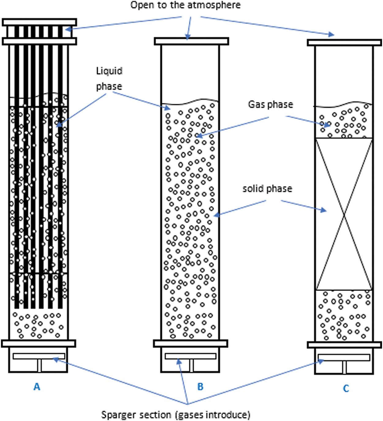
Figure 1: Three main three types of bubble columns: (A) bubble column with internals, (B) bubble/slurry bubble column, and (C) packed bed bubble column
Typically, flow regimes are determined either through subjective evaluations or through objective evidence. The input parameters for flow regime maps based on physical mechanisms are determined by the superficial velocities of liquid and gas, which are typically not measurably during on-line operations. In laboratory investigations, flow visualization is typically used to make subjective judgments [7,8], void fraction fluctuation obtained by radiation technique [9] or impedance technique [10] and pressure fluctuation [11].
In laboratory investigations, subjective judgements are usually made by:
a-flow visualization by [12].
b-void fraction fluctuation obtained by radiation technique [9].
c-void fraction fluctuation obtained by impedance technique [13].
d-void fraction fluctuation obtained by pressure fluctuation [11].
If the flow is fast and the void fraction is high or if the pipe is opaque, flow visualization may not be particularly accurate or realized. A many-to-many mapping between flow patterns and pressure fluctuations may occur from the two-phase pressure fluctuation’s dependency on so many different variables. Additionally, some challenges brought on by the existence of two-phase fluids are difficult to overcome, such as the possibility of gas being trapped in pressure sensor lines, as noted by Jones et al. in 1976 [14]. Measurements of the void fraction variation can be obtained using radiation absorption techniques like the X-ray and gamma-ray absorption methods.
However, it seems that impedance techniques, rather than radiation approaches, are a superior alternative to undertaking flow regime identification due to safety and financial reasons (even though the temperature effect still needs to be overcome). The immediate response from the impedance measurement also enables on-line characterization for the majority of practical applications.
In order to execute non-linear mapping from physical factors to flow regimes, statistical approaches and neural network systems have been used [15]. In this case, the neural network systems were more promising than the statistical approach. Previous neural network systems, on the other hand, needed to gather known input that is used for training as well as to undertake off-line benchmarking or cross-calibration.
2 Factors Affecting the Flow Regime
This section provides an explanation of the factors, such as mass transfer and bubble size distribution (BSD) and its forms, that affect flow regimes. Note that designs consider the exchange between gas in the form of air bubbles and liquid in the form of water. This assumption must be taken into account when altering gases or liquids in design calculations [8].
The fluid dynamics characteristics of bubble columns affect performance quality. For example, superficial gas velocity is the main factor affecting flow regimes in any multiphase system. Thus, two fundamental flow types are frequently seen to affect bubble column performance in most studies: homogeneous (bubbly flow) and heterogeneous (churn-turbulent flow) [16–18]. In homogeneous or bubbly flow, bubble size is uniformly distributed over the cross-sectional area of the column when superficial velocities are low and approximately less than 0.05 m/s [17]. Moreover, in homogeneous regimes, the parameter εG increases linearly with the increase in superficial gas velocity [19]. Therefore, at a certain gas velocity, the flow regime transitions from homogeneous to heterogeneous. Nonuniform bubble size and distribution and potential mixing are observed over the cross-sectional area of bubble columns at high superficial gas velocities approximately greater than 0.05 m/s. This regime is called the heterogeneous regime or churn-turbulent regime due to the high disturbance in the flow system inside the bubble column, as illustrated in Fig. 2. The homogenous regime at low superficial gas velocities is also known as the bubble flow regime when the bubbles are small in size, spherical in shape, and rise in the vertical direction. • The transition regime: when the gas velocities increase compared to the bubble flow regime causes less stability in bubble behavior, and the bubble characterizes. • The heterogeneous regime at usually high superficial gas velocities is also defined as a churn turbulent regime due to the gas velocities that generate a parabolic radial profile, including the large bubbles. • The slug flow regime can be defined when the gas phase has very high superficial velocities in a small diameter of the reactors. Then, the bubble coalescence to be very large diameter slugs in the column.
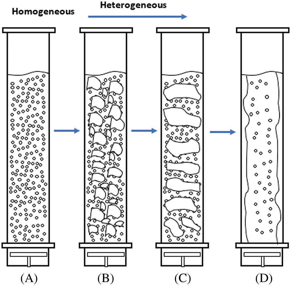
Figure 2: Types of flow regimes in multiphase flow systems in bubble columns. (A) Bubbly flow, (B) churn-turbulent flow, (C) sluggish flow, and (D) annular flow
2.2 Geometry and Operating Condition Mapping
Using flow maps to predict operational flow system information on the basis of the operating conditions and geometry of columns is important. These maps are used in many applications. For example, operational flow maps are utilized for large- and small-diameter two-phase flow systems [20]. Shah et al. established the best map that has been adopted as a design for bubble columns. The map for low-viscosity systems is applied for all flow systems, whether homogeneous, transitional, or heterogeneous, because of its dependence on the diameter of the bubble column and the velocity of gas–liquid transfer perpendicular to the surface area as shown in Fig. 3. The gas holdup was measured for four zones under different initial bubble modes [6].
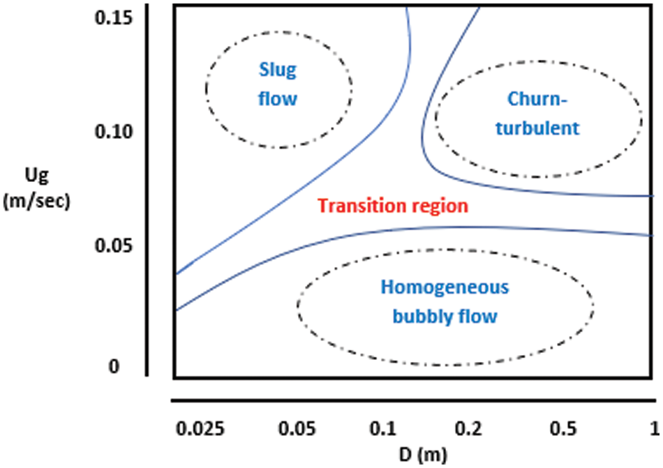
Figure 3: Schematic showing the different flow regimes based on operating conditions and column diameter [21]
Bubble sizes and shapes affect the flow regime behavior, and understanding and knowing these parameters are essential for bubble column design and performance. Current studies have demonstrated that the sizes, shapes, and distributions of bubbles exert a major effect on flow regimes due to their link to the bubble stability. Consequently, these parameters have a vital influence on hydrodynamics parameters, particularly εG distribution, inside bubble columns.
Along with εG, BSD provides an assessment of the interfacial area and is used in computational liquid dynamics (CFD) for model setup and validation. From a practical standpoint, BSD is a fundamental parameter of bubble column fluid dynamics. Its fluctuation is one of the primary causes of the effect of operational parameters on εG and the change in the flow regime. In addition to bubble forms, BSD (the aspect ratio) must be considered. Interface size and form are crucial for describing multiphase flows accurately.
εG is one of the main important dimensionless parameters characterizing the hydrodynamics of multiphase systems. It is defined as the volume fraction of gas in the total volume of the gas–liquid phases in bubble columns. εG depends on the period of time during which the gas remains inside the bubble column and the speed of its passage through the liquid [22]. The size of the reactor is affected by column design and operating conditions. Studies have shown that compared with the heterogeneous system, the homogeneous flow system is more prone to trapping gas because it is more sensitive to operating conditions [23,24].
Using the traditional Bernoulli’s law of energy conservation, we can calculate the void fraction.
where:
p: pressure.
FF = fraction pressure.
In a particular two-phase space, the void fraction is often expressed as the volume of vapor divided by the total volume of fluid. Rahim et al. [26] presented four generally used definitions of void fraction for various scenarios and measurement techniques: void fractions can be local, chordal, cross-sectional, and volumetric.
a-The local emptiness fraction is measured by using a tiny sensor to collect signals from a single spot.
b-The chordal void percent, which is employed in one-dimensional flows like intermittent (plug/slug) two-phase flow inside typically smaller channels, is defined as the length of the vapor over the entire length.
c-The percentage of cross-sectional area occupied by the vapor phase relative to the total cross-sectional area is known as the cross-sectional void fraction. Typically, optical or electrical techniques are used to measure this type of vacancy fraction.
d-The volumetric void fraction in a control volume is determined by dividing the volume of the vapor phase by the entire volume. By swiftly closing valves, one can determine the volumetric void fraction.
correlation εG
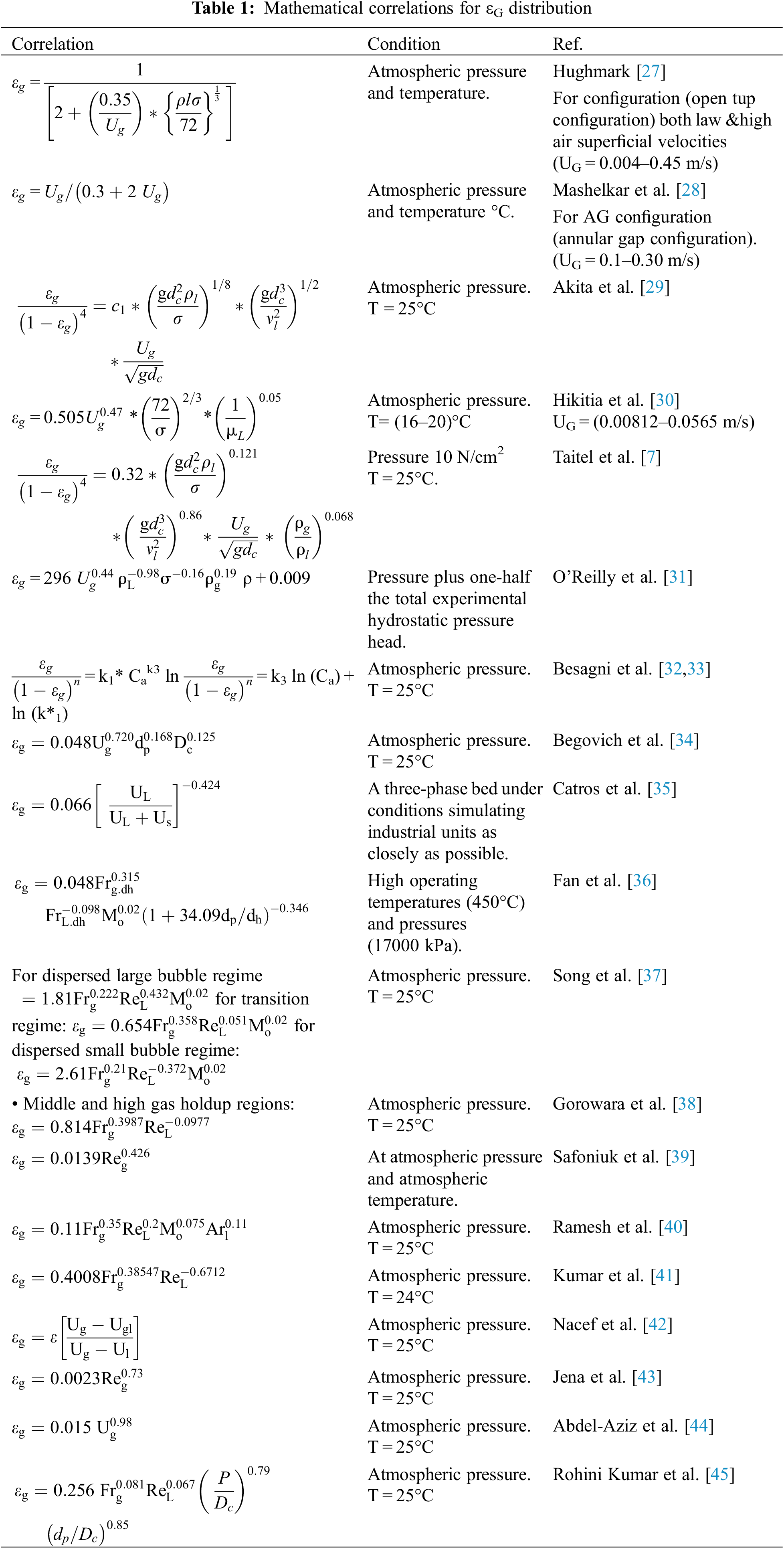
Many mathematical relations that are widely used to describe gas trapping (εG) have been studied previously as shown in Table 1.
Bubble columns can be operated in batch-wise, co-current, or countercurrent mode at UL = 0.01 m/s. Various researchers have shown that normally, low liquid velocities have no effect on εG because bubble acceleration due to no stagnant operation is minimal if UL is less than the bubble rise velocity [20].
Numerous authors have studied the properties of liquids in gas retention and mass transfer. They identified the liquid characteristics in terms of gas retention and mass transfer within the bubble column and discovered that liquid velocity in the presence of an opposite current has a strong actual effect on gas retention as represented by εG [46]. Therefore, gas retention increases and the value of εG is high if the current is opposite to the direction of the liquid, whereas εG is low if the current is in the direction of the liquid when velocities above 0.04 m/s are neglected [47]. Baawain et al. studied the relationship between mass transfer and bubble size and its effect on gas retention within a column in the presence of a current opposite to the liquid. They found that 5% of the weight of the gas and 1% of the bubble volume were retained due to the increase in the speed of bubbles but not in bubble size [48].
2.6 Bubble Column Configurations
Bubble column configurations are the main criteria that must be considered in the design of multiphase flow systems also there are important parameters such as Column size, Aspect ratio Gas sparger as shown in Fig. 4. Numerous studies have proven that large bubble column diameters (dc) result in high reductions in εG. Moreover, bubble size and movement are influenced by the column wall. Besagni et al. [49] studied the relationship between dc and εG and found that εG decreased with the increase in dc and that viscous fluids can be used when dc was 0.15–0.23 m [50]. Behkish et al. [51] demonstrated the relationship between dc and highly viscous fluids and proved that increasing dc increased the viscosity of fluids that can be used there are also two parameter effected in design of bubble column.
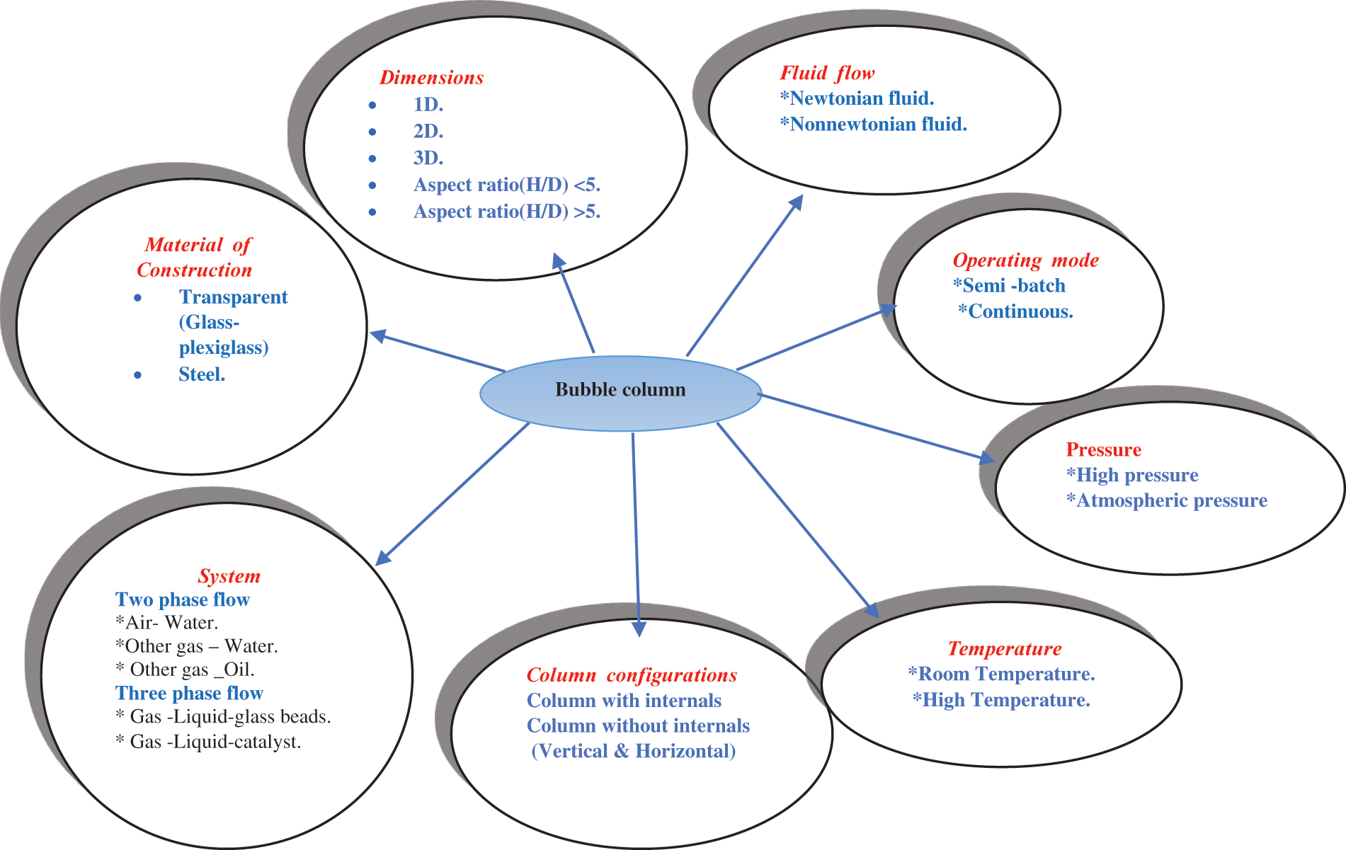
Figure 4: Conditions of bubble column
A-Aspect ratio
The ratio of the initial liquid height to the column diameter (H/D) is defined as aspect ratio. Zhany et al. [52] studied the values of εG with liquid movements in homogenous flow systems and demonstrated that εG decreased as the bubble column size was reduced. Bubble sizes larger than the size needed for equilibrium reduced the efficiency of integration between the liquid and gas phases. The aspect ratio up to critical has turned to decrease the gas hold up and destabilize the homogeneous flow regime. Aspect ratio decreases the transition velocity; however, it alone is not sufficient to provide reliable information on flow regime stability.
B-Gas sparger (gas inertia)
The gas sparger is the main component of the bubble column configuration. It is required for introducing gases into columns and has different designs and hole sizes. Moreover, it affects εG. The shape of the gas distributor affects the dynamics of bubbles entering through holes and those entering the reactor (bubble column). It imposes its effects on merging and substitution. Therefore, when a large-diameter distributor is used, large bubbles are ejected. By contrast, when a small-diameter distributor is used, small bubbles are ejected. The low-rise speed of small bubbles ensures that the bubbles remain for an adequate time in the reactor for fusion and replacement, making the εG obtained when a small-diameter distributor is used higher than that when a large-diameter distributor is applied [41]. Transition velocity decreases with an increase in hole size up to a certain hole size. A gas sparger with a small hole size and large resistance will lead to small initial bubble size and large gas holdup in the homogeneous and transition regimes. The large gas holdup contributes a high volumetric mass transfer coefficient, which is a desirable characteristic. However, the gas holdup exhibits an excess and a slump in the transition regime when the small initial bubble size was adopted. The gas holdup slump results in pressure fluctuation, back mixing, and liquid residence time which should be avoided. There were varied experiments data for illustrating this relationship between superficial gas velocity and gas holdup [22].
2.7 Effect of Liquid Properties
Viscosity has a dual effect on the liquid in a flow system. Besagni et al. studied the double effect of viscosity and found that εG increased nonlinearly and continuously if the viscosity of the liquid (μL) = 5% = 1.01 mPa s and small bubbles were produced but decreased significantly if the liquid viscosity was increased [36]. When viscosity is low, εG increases with an increase in the curve. The homogeneous regime is stabilized at low viscosity (4.25 mPa s) by increasing the liquid viscosity. Previous research has shown that the beginning gas velocity of the vortical spiral flow reduces with increasing viscosity at high viscosity (7.68 mPa s) [53]. An increase in viscosity in general advances flow regime transition.
Scanning previously reported studies revealed that εG can be increased by increasing the number of active compounds, such as ethanol and electrolytes, in reactors. This change may influence flow regimes [54].
Inorganic compounds and their concentrations have an essential relationship with εG. Specifically, high inorganic compound concentrations in reactors (bubble columns) lead to significant increases in εG. Moreover, low inorganic compound concentrations lead to reductions in εG in bubble columns. A study using three electrolytes at different concentrations revealed that flow dynamics parameters increased with the increase in inorganic compound concentrations. Laboratory experiments on the effect of inorganic salts on εG and flow regimes in bubble columns are summarized in Table 2. A previous study using three salt solutions, namely, Solutions of Na2SO4 (p.a. grade), NaCl (p.a. grade), and NaCl (kitchen quality) were used, and it was found that the purity of the salt had a significant impact on the behavior of the bubble column and that some salts could have auxiliary effects that could skew results (such as crystallization inside plate orifices) [55].
Previous studies revealed that the addition of organic materials to flow systems in bubble column reactors cause foaming, which intensifies with the increase in the concentrations of organic compounds. Foam helps extend the residence time of gases in liquids and increase εG, thus enhancing system efficiency. However, these studies also showed that foam not only forms due to the increase in the concentrations of organic compounds, it is also affected by the ratio of the diameter of the reactor to its height and the location of gas entry. Ethanol is one of the most important organic compounds used in such systems [56,57].
2.8 Influence of Gas Properties
Gas and liquid properties influence the performance of bubble columns particularly in the presence of a real reaction. When using different types of gases, the size of gas bubbles varies from one gas to another due to differences in properties, such as pressure and temperature. This difference causes a variation in bubble size and distribution. For example, when the gas density (ρG) increases, εG increases, indicating that the increase in ρG increases the residence time of the gas itself. Therefore, the use of the appropriate gas dispersion design should be considered to obtain the ideal operating condition of the system [58,59].
Given that in general, liquid is an incompressible fluid, it is not influenced by pressure. Pressure does not have a noticeable effect on εG because it controls the operating conditions in the case of gas. However, its effect is slight. Pressure has a weaker effect on homogeneous flow than on heterogeneous flow and can be 6, 7, or 10 MPa depending on the operating conditions [48]. In general, an increase in pressure results in an increase in transition velocity.
Some studies noted that increasing the temperature (Tc) does not affect flow dynamics parameters, such as εG. Meanwhile, Sato et al. [60] suggested that an inverse relationship exists between the temperature of the bubble column and εG. In general, increasing the temperature leads to the stage of evaporation, which helps release gas molecules to the surface quickly, resulting in a residence time that is insufficient for the completion of the reaction in the reactor. An increase in temperature increases the transition velocity and delays the flow regime transition.
2.8.3 Influence of Internals Hydrodynamics: “Holdup, Flow Regime”
Many times, bubble columns are investigated without taking internals into account (open tube bubble columns). However, in the majority of industrial applications, internal devices are frequently included to regulate heat transfer, promote bubble break-up, or prevent liquid phase back mixing. These components can significantly affect the multiphase flow inside the bubble column reactor, and it is still difficult to estimate these effects without doing experiments [61].
That the global column hydrodynamic is not significantly affected by the presence of internals. Most industrial multiphase reactors use internal structures for heat transfer from/to the system, for controlling the flow structures, and for back mixing in the column. The presence of the internals stabilizes the homogeneous flow regime in terms of transition gas velocity and transition holdup value [61].
All interior components, including perforated plates, baffles, vibrating helical springs, mixers, and heat exchanger tubes, are referred to as “internals” in this context. Instrumentation probes, downcomers, and risers with heat exchangers are all regarded as different types of internal barriers in commercial scale bubble columns.
Numerous studies have examined the properties of fluid dynamics locally or worldwide during the past few decades.
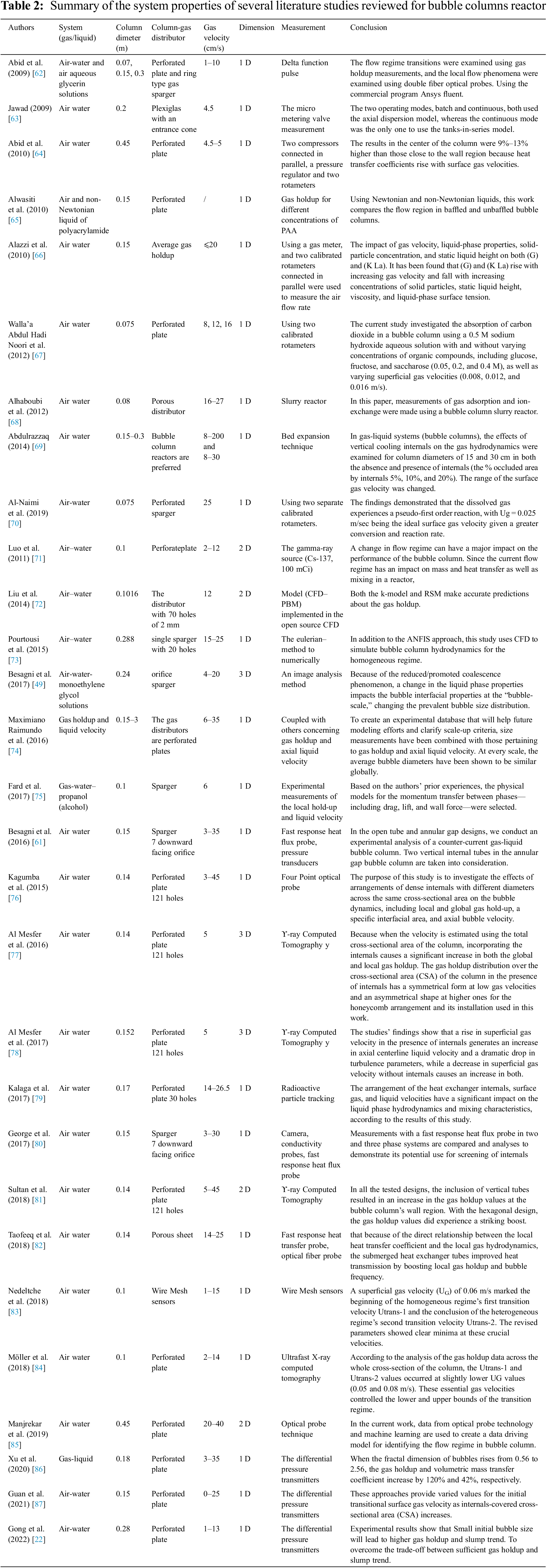
Studies on hydrodynamics parameters, particularly those related to flow regime hydrodynamics, are still rare. The distribution of G and bubble size should be studied, as shown in Table 2. Summary of the system properties of several literature studies reviewed for bubble columns reactor, in order to provide an ongoing multiscale assessment of bubble column fluid dynamics that takes into account the effects of heat and mass transfer.
Acknowledgement: The authors would like to thank the Missouri University of Science and Technology, the University of Technology-Iraq, and the Al Mustaqbal University College for financial support for this work. In addition, the authors would like to acknowledge the graduate student’s effort (Zahraa W. Hasan) in implementing the reviewer’s and the editor’s comments.
Funding Statement: The authors received no specific funding for this study.
Author Contributions: The authors confirm contribution to the paper as follows: study conception and design: Laith S. Sabri and Abbas J. Sultan; data collection: Ayat N. Mahmood; analysis and interpretation of results: Ayat N. Mahmood, Amer A. Abdulrahman, Hasan Shakir Majdi; draft manuscript preparation: Laith S. Sabri, Abbas J. Sultan and Muthanna H. Al-Dahhan. All authors reviewed the results and approved the final version of the manuscript.
Availability of Data and Materials: The data that support the findings of this study are available from the corresponding author, Laith S. Sabri, upon reasonable request.
Conflicts of Interest: The authors declare that they have no conflicts of interest to report regarding the present study.
References
1. Karn, A. (2017). Characterization of bubbly flow systems: A review. International Journal of Petrochemical Science & Engineering, 2(6), 286–290. [Google Scholar]
2. Yunos, M. A. S. M., Halim, N. K. A., Hussain, S. A., Yusoff, H. M., Sipaun, S. (2017). Investigations of bubble size, gas hold-up, and bubble rise velocity in quadrilateral bubble column using high-speed camera. American Journal of Engineering, Technology and Society, 4(1), 5–15. http://www.openscienceonline.com/journal/archive2?journalId=737&paperId=3685 [Google Scholar]
3. Kulkarni, A. V., Joshi, J. B. (2011). Design and selection of sparger for bubble column reactor. Part I: Performance of different spargers. Chemical Engineering Research and Design, 89(10), 1972–1985. https://doi.org/10.1016/j.cherd.2011.01.004 [Google Scholar] [CrossRef]
4. Lau, R., Mo, R., Sim, W. S. B. (2010). Bubble characteristics in shallow bubble column reactors. Chemical Engineering Research and Design, 88(2), 197–203. [Google Scholar]
5. Millán-Núñez, R., Santamaría-del-Ángel, E., Cajal-Medrano, R., Barocio-León, Ó. A. (1999). El delta del Río Colorado : Un ecosistema con alta productividad primaria. Ciencias Marinas, 25(4), 509–524. [Google Scholar]
6. Mezui, Y., Cartellier, A., Obligado, M. (2023). An experimental study on the liquid phase properties of a bubble column operated in the homogeneous and in the heterogeneous regimes. Chemical Engineering Science, 268, 118381. [Google Scholar]
7. Taitel, Y., Barnea, D., Dukler, A. E. (1980). Modelling flow pattern transitions for steady upward gas-liquid flow in vertical tubes. AIChE Journal, 26(3), 345–354. [Google Scholar]
8. Kataoka, I., Ishii, M., Mishima, K. (1983). Generation and size distribution of droplet in annular two-phase flow. Journal of Fluids Engineering, 105(2), 230–238. [Google Scholar]
9. Jones Jr, O. C., Zuber, N. (1975). The interrelation between void fraction fluctuations and flow patterns in two-phase flow. International Journal of Multiphase Flow, 2(3), 273–306. [Google Scholar]
10. Merilo, M., Dechene, R. L., Cichowlas, W. M. (1977). Void fraction measurement with a rotating electric field conductance gauge. Journal of Heat Transfer, 99(2), 330–332. [Google Scholar]
11. Matsui, G. (1984). Identification of flow regimes in vertical gas-liquid two-phase flow using differential pressure fluctuations. International Journal of Multiphase Flow, 10(6), 711–719. [Google Scholar]
12. Barnea, D., Luninski, Y., Taitel, Y. (1983). Flow pattern in horizontal and vertical two phase flow in small diameter pipes. The Canadian Journal of Chemical Engineering, 61(5), 617–620. [Google Scholar]
13. Tapucu, A., Merilo, M. (1977). Studies on diversion cross-flow between two parallel channels communicating by a lateral slot. II: Axial pressure variations. Nuclear Engineering and Design, 42(2), 307–318. [Google Scholar]
14. Jones Jr, O. C., Delhaye, J. M. (1976). Transient and statistical measurement techniques for two-phase flows: A critical review. International Journal of Multiphase Flow, 3(2), 89–116. [Google Scholar]
15. Mi, Y., Ishii, M., Tsoukalas, L. H. (2001). Flow regime identification methodology with neural networks and two-phase flow models. Nuclear Engineering and Design, 204(1–3), 87–100. [Google Scholar]
16. Noraishah, O., Mohd, A. H., Ainul, M. T. (2011). The hydrodynamics studies of bubbling phenomena using high speed camera: A visual observation. NTC 2011: Nuclear Technical Convention 2011, Bangi, Malaysia. [Google Scholar]
17. Hooshyar, N. (2013). Hydrodynamics of structured slurry bubble columns. In: Chemical engineering. Iran: University of Tehran. [Google Scholar]
18. Buwa, V. V., Ranade, V. V. (2002). Dynamics of gas–liquid flow in a rectangular bubble column: Experiments and single/multi-group CFD simulations. Chemical Engineering Science, 57(22–23), 4715–4736. [Google Scholar]
19. Kawagoe, K. (1976). Flow-pattern and gas-holdup conditions in gas-sparged contactors. International Chemical Engineering, 16, 176–183. [Google Scholar]
20. Wu, B., Firouzi, M., Mitchell, T., Rufford, T. E., Leonardi, C. et al. (2017). A critical review of flow maps for gas-liquid flows in vertical pipes and annuli. Chemical Engineering Journal, 326, 350–377. https://doi.org/10.1016/j.cej.2017.05.135 [Google Scholar] [CrossRef]
21. Krishna, R., van Baten, J. M., Urseanu, M. I. (2000). Three-phase eulerian simulations of bubble column reac (Urseanu and Krishna, 2000). Tors operating in the churn-turbulent regime: A scale up strategy. Chemical Engineering Science, 55(16), 3275–3286. [Google Scholar]
22. Gong, C. K., Xu, X., Yang, Q. (2022). Gas holdup at dynamic equilibrium region of a bubble column: Effect of bubble generator performance. Chemical Engineering Journal, 443, 136382. [Google Scholar]
23. Behkish, A., Lemoine, R., Sehabiague, L., Oukaci, R., Morsi, B. I. (2007). Gas holdup and bubble size behavior in a large-scale slurry bubble column reactor operating with an organic liquid under elevated pressures and temperatures. Chemical Engineering Journal, 128(2–3), 69–84. [Google Scholar]
24. Youssef, A. A., Al-Dahhan, M. H., Dudukovic, M. P. (2013). Bubble columns with internals: A review. International Journal of Chemical Reactor Engineering, 11(1). [Google Scholar]
25. Jia, J., Babatunde, A., Wang, M. (2015). Void fractin measurement of gas-liquid two-phase flow from differential pressure. Flow Measurement & Instrumentation, 41, 75–80. [Google Scholar]
26. Rahim, E., Revellin, R., Thome, J., Bar-Cohen, A. (2011). Characterization and prediction of two-phase flow regimes in miniature tubes. International Journal of Multiphase Flow, 37(1), 12–23. [Google Scholar]
27. Hughmark, G. A. (1967). Holdup and mass transfer in bubble columns. Industrial & Engineering Chemistry Process Design and Development, 6(2), 218–220. [Google Scholar]
28. Mashelkar, R. A., Sharma, M. M. (1970). Mass transfer in bubble and packed bubble columns. Transactions of the Institution of Chemical Engineers, 48, T162–T162. [Google Scholar]
29. Akita, K., Yoshida, F. (1973). Gas holdup and volumetric mass transfer coefficient in bubble columns. Effects of liquid properties. Industrial & Engineering Chemistry Process Design and Development, 12(1), 76–80. [Google Scholar]
30. Hikita, H., Kikukawa, H. (1974). Liquid-phase mixing in bubble columns: Effect of liquid properties. The Chemical Engineering Journal, 8(3), 191–197. [Google Scholar]
31. O’Reilly, C. A., Chatman, J. (1986). Organizational commitment and psychological attachment: The effects of compliance, identification, and internalization on prosocial behavior. Journal of Applied Psychology, 71(3), 492. [Google Scholar]
32. Besagni, G., Guédon, G., Inzoli, F. (2014). Experimental investigation of counter current air-water flow in a large diameter vertical pipe with inners. Journal of Physics: Conference Series, 547, 12024. [Google Scholar]
33. Besagni, G., Guédon, G. R., Inzoli, F. (2016). Annular gap bubble column: Experimental investigation and computational fluid dynamics modeling. Journal of Fluids Engineering, 138(1), 011302. [Google Scholar]
34. Begovich, J. M., Watson, J. S. (1978). Hydrodynamic characteristics of three-phase fluidized beds, vol. 3, pp. 190–195. Cambridge: Cambridge University Press. [Google Scholar]
35. Catros, A., Bernard, J. R., Briens, C., Bergougnou, M. A. (1985). Gas holdup above the bed surface and grid gas jet hydrodynamics for three phase fluidized beds. The Canadian Journal of Chemical Engineering, 63(5), 754–759. [Google Scholar]
36. Fan, L. S., Bavarian, F. R., Gorowara, I., Kreischer, B. E. (1987). Hydrodynamics of gas-liquid-solid fluidization under high gas hold-up conditions. Powder Technology, 53, 285–29. [Google Scholar]
37. Song, G. H., Bavarian, F., Fan, L. S. (1989). Hydrodynamics of three-phase fluidized bed containing cylindrical hydrotreating catalysts. Canadian Journal of Chemical Engineering, 67, 265–275. [Google Scholar]
38. Gorowara, R. L., Fan, L. S. (1990). Effect of surfactants on three-phase fluidized bed hydrodynamics. Industrial and Engineering Chemistry Research, 29, 882–889. [Google Scholar]
39. Safoniuk, M., Grace, J. R., Hackman, L., McKnight, C. A. (1999). Use of dimensional similitude for scale-up of hydrodynamics in three-phase fluidized beds. Chemical Engineering Science, 54(21), 4961–4966. [Google Scholar]
40. Ramesh, K., Murugesan, T. (2002). Minimum fluidization velocity and gas holdup in gas–liquid–solid fluidized bed reactors. Journal of Chemical Technology & Biotechnology, 136, 129–136. [Google Scholar]
41. Kumar, R. N., Vinod, A. V. (2014). Oxygen mass transfer in bubble column bioreactor. Periodica Polytechnica Chemical Engineering, 58(1), 21–30. [Google Scholar]
42. Nacef, S., Poncinb, S., Bouguettouchaa, A., Wild, G. (2007). Drift flux concept in two- and three-phase reactors. Chemical Engineering Science, 62, 7530. [Google Scholar]
43. Jena, H. M., Sahoo, B. K., Roy, G. K., Meikap, B. C. (2008). Characterization of hydrodynamic properties of a gas–liquid–solid three-phase fluidized bed with regular shape spherical glass bead particles. Chemical Engineering Journal, 145(1), 50–56. [Google Scholar]
44. Abdel-aziz, M. H., El-abd, M. Z., Bassyouni, M. (2016). Heat and mass transfer in three phase Fl uidized bed containing high density particles at high gas velocities. International Journal of Thermal Sciences, 102, 145–153. [Google Scholar]
45. Rohini Kumar, P., Ramesh, K. V., Venkateswarlu, P. (2017). Phase holdups in a three-phase fluidized bed in the presence of coaxially placed string of spheres internal. IOP Conference Series: Materials Science and Engineering, 225, 012210. [Google Scholar]
46. Khalil, I. A., Kogure, K., Akita, H., Harashima, H. (2006). Uptake pathways and subsequent intracellular trafficking in nonviral gene delivery. Pharmacological Reviews, 58(1), 32–45. [Google Scholar] [PubMed]
47. Rollbusch, P., Bothe, M., Becker, M., Ludwig, M., Grünewald, M. et al. (2015). Bubble columns operated under industrially relevant conditions–current understanding of design parameters. Chemical Engineering Science, 126, 660–678. [Google Scholar]
48. Baawain, M. S., El-Din, M. G., Smith, D. W. (2007). Artificial neural networks modeling of ozone bubble columns: Mass transfer coefficient, gas hold-up, and bubble size. Ozone: Science and Engineering, 29(5), 343–352. [Google Scholar]
49. Besagni, G., Inzoli, F. (2017). The effect of liquid phase properties on bubble column fluid dynamics: Gas holdup, flow regime transition, bubble size distributions and shapes, interfacial areas and foaming phenomena. Chemical Engineering Science, 170, 270–296. https://doi.org/10.1016/j.ces.2017.03.043 [Google Scholar] [CrossRef]
50. Ding, R., Zhang, X., Chen, G., Wang, H., Kishor, R. et al. (2017). High-performance piezoelectric nanogenerators composed of formamidinium lead halide perovskite nanoparticles and poly (vinylidene fluoride). Nano Energy, 37, 126–135. [Google Scholar]
51. Laurent, S., Romain, L., Arsam, B., Yannick, H., Mariela, S. et al. (2008). Modeling and optimization of a large-scale slurry bubble column reactor for producing 10,000 bbl/day of fischer–tropsch liquid hydrocarbons. Journal of the Chinese Institute of Chemical Engineers, 39(2), 169–179. [Google Scholar]
52. Qiao, Z., Wang, Z., Zhang, C., Yuan, S., Zhu, Y. et al. (2012). PVAm–PIP/PS composite membrane with high performance for CO2/N2 separation. AIChE Journal, 59(4), 215–228. [Google Scholar]
53. Olivieri, G., Russo, M. E., Simeone, M., Marzocchella, A., Salatino, P. (2011). Effects of viscosity and relaxation time on the hydrodynamics of gas-liquid systems. Chemical Engineering Science, 66(14), 3392–3399. https://doi.org/10.1016/j.ces.2011.01.027 [Google Scholar] [CrossRef]
54. Pjontek, D., Parisien, V., Macchi, A. (2014). Bubble characteristics measured using a monofibre optical probe in a bubble column and freeboard region under high gas holdup conditions. Chemical Engineering Science, 111, 153–169. https://doi.org/10.1016/j.ces.2014.02.024 [Google Scholar] [CrossRef]
55. Zahradník, J., Fialova, M., Ru, M., Drahos, J., Kastanek, F. et al. (1997). Duality of the gas-liquid flow regimes in bubble column reactors. Chemical Engineering Science, 52(21–22), 3811–3826. [Google Scholar]
56. Besagni, G., Mereu, R., di Leo, G., Inzoli, F. (2015). A study of working fluids for heat driven ejector refrigeration using lumped parameter models. International Journal of Refrigeration, 58, 154–171. [Google Scholar]
57. Hur, Y. G., Yang, J. H., Jung, H., Lee, K. Y. (2014). Continuous alcohol addition in vaporized form and its effect on bubble behavior in a bubble column. Chemical Engineering Research and Design, 92(5), 804–811. https://doi.org/10.1016/j.cherd.2013.08.006 [Google Scholar] [CrossRef]
58. Besagni, G., Gallazzini, L., Inzoli, F. (2018). Effect of gas sparger design on bubble column hydrodynamics using pure and binary liquid phases. Chemical Engineering Science, 176, 116–126. https://doi.org/10.1016/j.ces.2017.10.036 [Google Scholar] [CrossRef]
59. Besagni, G., Inzoli, F., De Guido, G., Pellegrini, L. A. (2017). The dual effect of viscosity on bubble column hydrodynamics. Chemical Engineering Science, 158, 509–538. https://doi.org/10.1016/j.ces.2016.11.003 [Google Scholar] [CrossRef]
60. Sato, Y., Hirose, T., Takahashi, F., Toda, M. (1973). Pressure loss and liquid holdup in packed bed reactor with cocurrent gas-liquid down flow. Journal of Chemical Engineering of Japan, 6(2), 147–152. [Google Scholar]
61. Al Mesfer, M. K., Sultan, A. J., Al-Dahhan, M. H. (2016). Impacts of dense heat exchanging internals on gas holdup cross-sectional distributions and profiles of bubble column using gamma ray computed tomography (CT) for FT synthesis. Chemical Engineering Journal, 300, 317–333. [Google Scholar]
62. Abid, M. F., Jameel, F. S. (2009). Scale effects on the hydrodynamics of bubbl e column. Engineering and Technology Journal, 27(10), 1–23. [Google Scholar]
63. Jawad, A. H. (2009). Studies pressure drop of gas-non-newtonian liquid two phase flow in bubble column. Engineering and Technology Journal, 27(7), 1–15. [Google Scholar]
64. Abid, B. A., Abdulmohsin, R. S. (2010). Heat transfer characteristics in a large-scale bubble column operating in a semi–batch mod. Engineering and Technology Journal, 28(3), 562–578. [Google Scholar]
65. Alwasiti, A. A., Alsudany, F. T., Raad, A. (2010). Effect of baffles on homogenous-heterogeneous regime in two phase bubble column with non-newtonian liquid. Engineering and Technology Journal, 28(24), 6954–6969. [Google Scholar]
66. Alazzi, A. A. R. N. J. (2010). Gas hold-up and volumetric liquid-phase mass transfer coefficient in solid-suspended bubble columns with draught tube. Engineering and Technology Journal, 28(7), 1464–1483. [Google Scholar]
67. Muslem, M. A. (2012). Enhancement of carbon dioxide absorption in caustic soda by organic solutes addition. Engineering and Technology Journal, 30(15), 1–21. [Google Scholar]
68. Alhaboubi, N., Nori, N., Hamad, M. F. (2012). Chlorine removal with activated carbon using bubble column. Engineering and Tech Journal, 30(9), 15–37. [Google Scholar]
69. Abdulrazzaq, B. S. (2014). Fluid dynamic in bubble columns with heat exchanger internals. Engineering and Technology Journal, 32(11), 1–15. [Google Scholar]
70. Al-Naimi, S., Jasim, F., Kokaz, A. (2019). Dynamic study of carbon dioxide absorption using promoted absorbent in bubble column reactor. Engineering and Technology Journal, 37(1C), 70–78. [Google Scholar]
71. Luo, H. P., Al-Dahhan, M. H. (2011). Verification and validation of CFD simulations for local flow dynamics in a draft tube airlift bioreactor. Chemical Engineering Science, 66(5), 907–923. [Google Scholar]
72. Liu, Y., Hinrichsen, O. (2014). Study on CFD–PBM turbulence closures based on k–ε and reynolds stress models for heterogeneous bubble column flows. Computers & Fluids, 105, 91–100. [Google Scholar]
73. Pourtousi, M., Sahu, J. N., Ganesan, P., Shamshirband, S., Redzwan, G. (2015). A combination of computational fluid dynamics (CFD) and adaptive neuro-fuzzy system (ANFIS) for prediction of the bubble column hydrodynamics. Powder Technology, 274, 466–481. [Google Scholar]
74. Maximiano Raimundo, P., Cloupet, A., Cartellier, A. H., Beneventi, D., Augier, F. (2018). Hydrodynamics and scale-up of bubble columns in the heterogeneous regime: Comparison of bubble size, gas holdup and liquid velocity measured in 4 bubble columns from 0.15 m to 3 m in diameter. Chemical Engineering Science, 198, 52–61. https://doi.org/10.1016/j.ces12.043ï [Google Scholar] [CrossRef]
75. Fard, M. G., Stiriba, Y., Gourich, B., Vial, C., Grau, F. X. (2020). Euler-euler large eddy simulations of the gas–liquid flow in a cylindrical bubble column. Nuclear Engineering and Design, 369, 110823. [Google Scholar]
76. Kagumba, M., Al-Dahhan, M. H. (2015). Impact of internals size and configuration on bubble dynamics in bubble columns for alternative clean fuels production. Industrial & Engineering Chemistry Research, 54(4), 1359–1372. [Google Scholar]
77. Sabri, L. S., Sultan, A. J., Majdi, H. S., Jebur, S. K., Al-Dahhan, M. H. (2022). A detailed hydrodynamic study of the split-plate airlift reactor by using non-invasive gamma-ray techniques. ChemEngineering, 6(1), 18. https://doi.org/10.3390/chemengineering6010018 [Google Scholar] [CrossRef]
78. Al Mesfer, M. K., Sultan, A. J., Al-Dahhan, M. H. (2017). Study the effect of dense internals on the liquid velocity field and turbulent parameters in bubble column for fischer–tropsch (FT) synthesis by using radioactive particle tracking (RPT) technique. Chemical Engineering Science, 161, 228–248. [Google Scholar]
79. Kalaga, D. V., Yadav, A., Goswami, S., Bhusare, V., Pant, H. J. et al. (2017). Comparative analysis of liquid hydrodynamics in a co-current flow-through bubble column with densely packed internals via radiotracing and radioactive particle tracking (RPT). Chemical Engineering Science, 170, 332–346. [Google Scholar]
80. George, K. J. H., Jhawar, A. K., Prakash, A. (2017). Investigations of flow structure and liquid mixing in bubble column equipped with selected internals. Chemical Engineering Science, 170, 297–305. [Google Scholar]
81. Sultan, A. J., Sabri, L. S., Al-Dahhan, M. H. (2018). Impact of heat-exchanging tube configurations on the gas holdup distribution in bubble columns using gamma-ray computed tomography. International Journal of Multiphase Flow, 106, 202–219. [Google Scholar]
82. Taofeeq, H., Al-Dahhan, M. (2018). Heat transfer and hydrodynamics in a gas-solid fluidized bed with vertical immersed internals. International Journal of Heat and Mass Transfer, 122, 229–251. [Google Scholar]
83. Nedeltchev, S., Möller, F., Hampel, U., Schubert, M. (2018). Flow regime transitions in a bubble column with internals based on a novel approach. Journal of Chemical Engineering of Japan, 51(4), 373–382. [Google Scholar]
84. Möller, F., Lau, Y. M., Seiler, T., Hampel, U., Schubert, M. (2018). A study on the influence of the tube layout on sub-channel hydrodynamics in a bubble column with internals. Chemical Engineering Science, 179, 265–283. [Google Scholar]
85. Manjrekar, O. N., Dudukovic, M. P. (2019). Identification of flow regime in a bubble column reactor with a combination of optical probe data and machine learning technique. Chemical Engineering Science: X, 2, 100023. https://doi.org/10.1016/j.cesx.2019.100023 [Google Scholar] [CrossRef]
86. Xu, X., Wang, J., Yang, Q., Wang, L., Lu, H. et al. (2020). Bubble size fractal dimension, gas holdup, and mass transfer in a bubble column with dual internals. Chinese Journal of Chemical Engineering, 28(12), 2968–2976. [Google Scholar]
87. Guan, X., Yang, N. (2021). Characterizing regime transitions in a bubble column with internals. AIChE Journal, 67(5), e17167. [Google Scholar]
Cite This Article
 Copyright © 2024 The Author(s). Published by Tech Science Press.
This work is licensed under a Creative Commons Attribution 4.0 International License , which permits unrestricted use, distribution, and reproduction in any medium, provided the original work is properly cited.
 Downloads
 Citation Tools