
 Submit a Paper
 Propose a Special lssue
 Open Access
ARTICLE

A New Heat Transfer Model for Multi-Gradient Drilling with Hollow Sphere Injection
1 School of Petroleum and Natural Gas Engineering, Changzhou University, Changzhou, China
2 CNPC Research Institute of Engineering Technology Co., Ltd., Beijing, China
3 National Engineering Research Center for Oil & Gas Drilling and Completion Technology, Beijing, China
4 College of Petroleum Engineering, China University of Petroleum (Beijing), Beijing, China
5 College of Petroleum, Karamay Campus, China University of Petroleum (Beijing), Beijing, China
* Corresponding Authors: Jiangshuai Wang. Email: ,
Fluid Dynamics & Materials Processing 2024, 20(3), 537-546. https://doi.org/10.32604/fdmp.2023.030430
Received 05 April 2023; Accepted 08 June 2023; Issue published 12 January 2024
 View Full Text
 Download PDF
Abstract
Multi-gradient drilling is a new offshore drilling method. The accurate calculation of the related wellbore temperature is of great significance for the prediction of the gas hydrate formation area and the precise control of the wellbore pressure. In this study, a new heat transfer model is proposed by which the variable mass flow is properly taken into account. Using this model, the effects of the main factors influencing the wellbore temperature are analyzed. The results indicate that at the position where the separation injection device is installed, the temperature increase of the fluid in the drill pipe is mitigated due to the inflow/outflow of hollow spheres, and the temperature drop of the fluid in the annulus also decreases. In addition, a lower separation efficiency of the device, a shallower installation depth and a smaller circulating displacement tend to increase the temperature near the bottom of the annulus, thereby helping to reduce the hydrate generation area and playing a positive role in the prevention and control of hydrates in deepwater drilling.Keywords
On a global scale, marine oil and gas resources are very abundant. Deepwater drilling is a highly beneficial and strategic task. However, in contrast, narrow density windows are an unavoidable problem [1–3]. It affects the success or failure and risk of deepwater drilling. In detail, complex situations such as overflow, well kick, and gas invasion are closely related to them. In 1990, a new revolutionary technology emerged, which was dual-gradient drilling. It can solve some problems in deep water drilling [4–6]. However, the huge cost and equipment limit the commercial application and expansion of this technology. Many drilling contractors do not use these bases due to economic burden. Even so, technological updates have not stopped. In recent years, researchers have developed a new offshore drilling technology based on the idea of injecting lightweight media by use of a device. It is the multi-gradient drilling with hollow sphere injection [7,8].
In deep water drilling, accurate temperature is the foundation of pressure control and hydrate prediction [9,10]. In this regard, the main basic models are already relatively mature. However, most of these models are based on “constant mass” flow heat transfer, which is a conventional approach for establishing models. For example, a heat transfer model was established during injection by Ramey Jr [11] in 1962. Then, a new heat transfer model was established considering the throttling cooling effect by Sagar et al. [12] in 1991. In 2006, a new model was established for heat pipe by Ma et al. [13]. In 2021, here is an interesting study conducted by Wang et al. [14]. In this model, the influence of the cuttings was considered in heat transfer process. Until the past three years, many models have been developed. For example, a non-isothermal multi-phase flow model established by Zhang et al. [15] in 2022, a fully transient wellbore multiphase flow model established by Yang et al. [16] in 2022, a simplified heat transfer and pressure model established by Yang et al. [17] in 2022. Recently, it is very noteworthy that variable mass flow has become a hot topic in shale oil wells. Then, in 2023, a new heat transfer model was established in shale oil wells by Yin et al. [18]. However, in this model, the variable mass flow phenomenon between the annulus and the formation, which is different from the variable mass flow phenomenon between the drill pipe and the annulus. Moreover, the variable mass flow point in this model is single, while the variable mass flow point for multi gradient drilling is complex and variable.
Based on the above current situation and challenges, a new heat transfer model for multi-gradient drilling with hollow sphere injection is necessary developed. Moreover, the multi position variable mass flow must be integrated into the model establishment process. Therefore, a very practical model was established for the new offshore drilling method, considering its unique flow characteristics and drilling technology. Moreover, the reliability of the model and some numerical simulation works have been completed. These works have important value for the progress of drilling technology and the extraction of hydrates.
2 Multi-Gradient Drilling with Hollow Sphere Injection
During multi-gradient drilling, the hollow sphere and drilling fluid are mixed in ground. Then, the hollow spheres will be separated into the annulus when the mixed fluid flow through the device. Therefore, there will be fluids of different densities in the annulus above the device. By designing the multi-device at different points, multiple pressure gradients can be formed in wellbore. Fig. 1 shows a schematic diagram of multi-gradient drilling with hollow sphere injection.
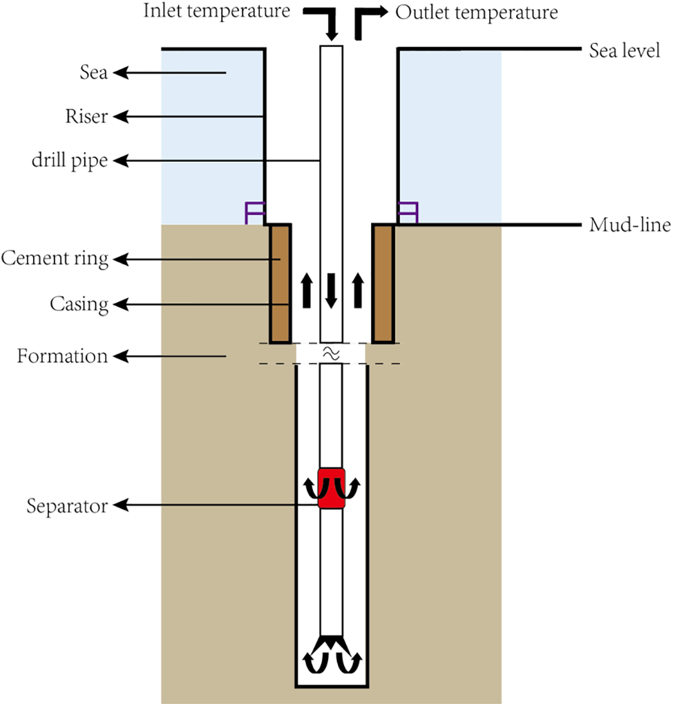
Figure 1: Multi-gradient drilling with hollow sphere injection
3 Establishment and Solution of Heat Transfer Model
Before establishing a new model, the following assumptions are prerequisites. 1) The fluid temperature in the drill pipe and in the annulus does not change in the radial direction. 2) There is a radius of the undisturbed formation. Generally, it is considered to be 3.05 m [19]. 3) The influence of variable mass heat transfer, the hollow sphere on the thermophysical parameters of the mixed fluid are considered at the position with device. 4) The influence of temperature and pressure on fluid thermophysical parameters is considered [20,21].
3.2 Governing Equations for Heat Transfer Model
In Figs. 2a and 2c, in general location without the device, the heat transfer in multi-gradient drilling wellbore is constant mass flow as the type of “one in and one out”. However, at a special position with the device is installed, it is the variable mass flow heat transfer as the type of “one in and two out” or “two in and one out”. It can be seen in Figs. 2b and 2d. According to the law of conservation of energy, the control equations of the temperature field model can be established for the fluids different positions.
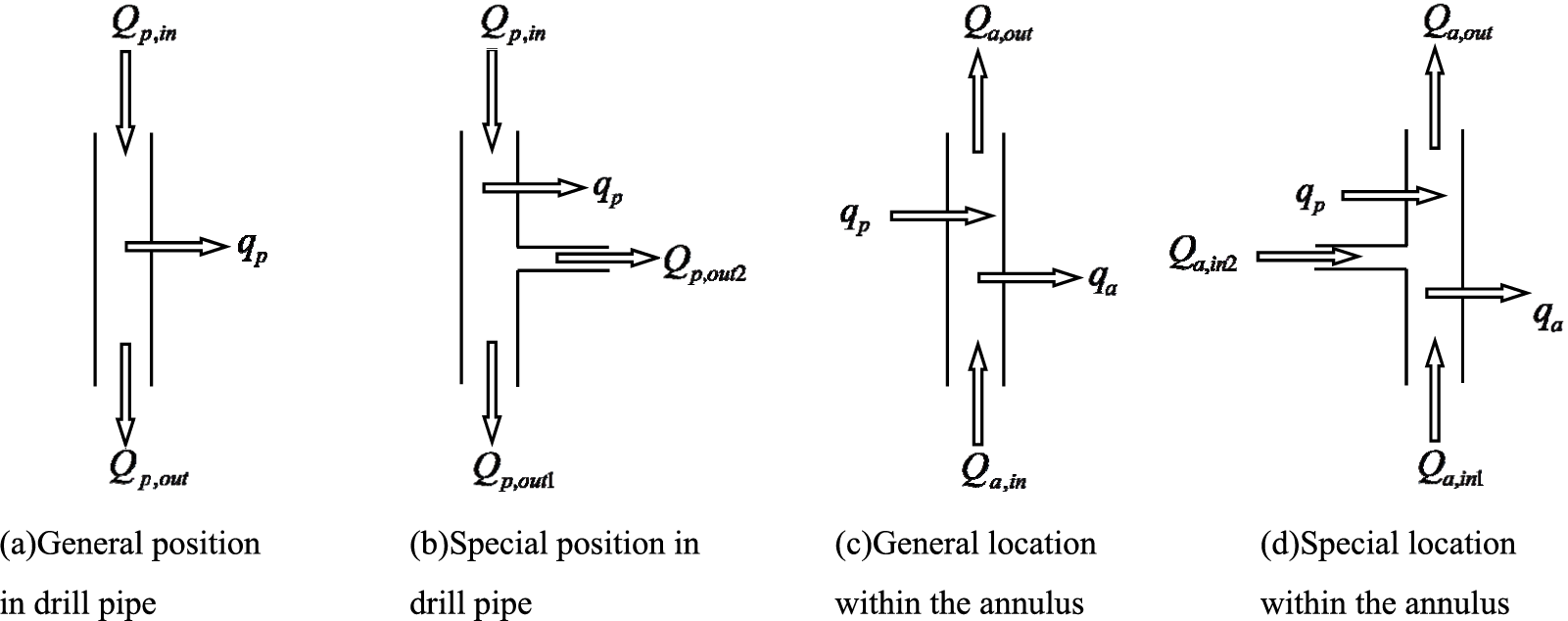
Figure 2: Schematic diagram of fluid heat transfer at different positions for multi-gradient drilling
(1) Control equation for general position in drill pipe
Among:
After fusion and simplification, we can obtain:
Among:
Qp,in, the heat of fluids into the drill pipe, J. Qp,out, the heat of fluids out of the drill pipe, J. qp, the heat in the form of transfer between the drill pipe and the annulus, J. Qp,change, the heat change, J. Cp, the specific heat capacity of the fluid into the drill pipe, J/(kg·°C). mp, the mass rate of the fluid into the drill pipe, kg/s. dp, the outer diameter of the drill pipe, m. kp, the thermal conductivity of the drill pipe, W/(m·°C). tp, the thickness of the drill pipe, m. ρp, the density of the fluid into the drill pipe, kg/m3. Ap, the area of drill pipe flow channel, m2. ΔL, the size of micro-element, m. Δt, the time step, s.
(2) Control equation at special position in drill pipe
Among:
After fusion and simplification, we can obtain:
Among:
Qp,out1, the heat of the fluid out of the drill pipe, J. Qp,out2, the heat of the hollow sphere out of the drill pipe, J. Cp1, the specific heat capacity of the fluid out of the drill pipe, J/(kg·°C). mp1, the mass flow rate of the fluid out of the drill pipe, kg/s. Cp2, the specific heat capacity the hollow sphere, J/(kg·°C). mp2, the mass rate of the hollow sphere, kg/s. ρp1, the density of the fluid out of the drill pipe, kg/m3. ρp2, the density of the hollow sphere, kg/m3.
(3) Controlling equation at general position in annulus
Among:
After fusion and simplification, we can obtain:
Among:
Qa,in, the heat of the fluid into annulus, J. Qa,out, the heat of the fluid out of annulus, J. qa, the heat in the form of transfer between the annulus and the formation, J. Qa,change, the heat change, J. Ca, the specific heat capacity of the fluid into the annulus, J/(kg·°C). ma, the mass rate of the fluid into the annulus, kg/s. dc, the outer diameter of the cylinder where the temperature is the original temperature, m. kf, the thermal conductivity of formation or riser, W/(m·°C). twellwall, the distance between the wellwall and the location where the temperature is the original temperature, m. ρa, the density of the fluid into the annulus, kg/m3. Aa, the area of annulus, m2.
(4) Control equation at special position in annulus
Among:
After fusion and simplification, we can obtain:
Among:
Qa,in1, the heat of fluid into annulus, J. Qa,in2, the heat of the hollow sphere into the annulus, J. Ca1, the specific heat capacity of the fluid into the annulus, J/(kg·°C). ma1, the mass rate of the fluid into the annulus, kg/s. Ca2, the specific heat capacity of the hollow sphere into annulus, J/(kg·°C). ma2, the mass rate of the hollow sphere into annulus, kg/s. ρa1, the density of the fluid into the annulus, kg/m3. ρa2, the density of the hollow sphere, kg/m3.
For the established model in this paper, the iterative solving algorithm is used to obtain accurate and stable temperature data. The specific solution steps are as follow.
The first step: the annular temperature is assumed to be the original ground temperature T0a,L= Tg,L. Using formulas (2) and (4) to calculate the temperature distribution in the drill pipe Tip,L.
The second step: substituting the temperature Tip,L in the drill pipe into formulas (6) and (8) calculating the temperature distribution in the annulus Tia,L.
The third step: calculating the annular temperature Tia,L and then substituting the formula again (2) and (4) recalculate temperature distribution in drill pipe Ti+1p,L.
The forth step: using the temperature inside the drill pipe Ti+1p,L to substitute into formulas (6) and (8), and then recalculating the temperature distribution in the annulus Ti+1a,L. Repeat steps 3) and 4) until the annular temperature distribution satisfies the following judgment criteria in formula (9).
Finally, the calculation result is considered to be stable.
In this formula, the accuracy of the model depends on the Etolerance. The larger the value is, the higher the model calculation accuracy is, while the longer the model calculation time is. In addition, the net size is set 50 m.
The phase equilibrium conditions of natural gas hydrate used in this paper has been established by Li et al. [22].
In Fig. 3, the comparison result shows that the consistency is very good, and the model is reliable. In detail, the relative error between the two is within 5%.
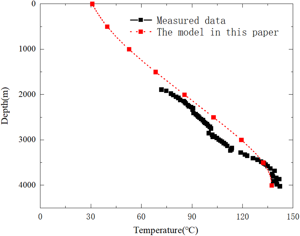
Figure 3: Model verification comparison
The basic parameters are as follows. The well depth is 2300 m. The water depth is 800 m. The casing shoe depth is 1500 m. The diameter of drill pipe is 0.127 m and the inner diameter is 0.109 m. The diameter of drill bit is 0.2159 m. The outer diameter of casing is 0.340 m and inner diameter is 0.318 m. The inner diameter of riser is 0.4949 m. and outer diameter is 0.533 m. The flow rate is 40 L/s. The density of fluid is 1127 kg/m3. The density of hollow sphere is 500 kg/m3. Injection fluid temperature is 25°C. The thermal conductivity of drill pipe is 43 W/(m·°C). The thermal conductivity of riser is 43 W/(m·°C). The thermal conductivity of formation is 2.25 W/(m·°C). The specific heat capacity of fluid is 4180 J/(kg·°C). The thermal conductivity of fluid is 0.73 W/(m·°C). The specific heat capacity of hollow sphere is 1500 J/(kg·°C). The separation efficiency of the device is 50%. The installation location of the device is selected at 1500 and 2100 m.
4.1 Influence of Volume Fraction Injected into Hollow Spheres on Annular Temperature
In Fig. 4, we can get that at the position with device, the magnitude of temperature increase in the drill pipe decreases. Similarly, the temperature drop in the annulus also decreases. The reason is that at the position with device, the outflow of the hollow sphere takes away part of the heat. So, the magnitude of temperature increase in the drill pipe decreases. For the fluid in the annulus, the inflow of the hollow sphere brings a part of the heat. So, the temperature drop of the fluid in the annulus decreases.
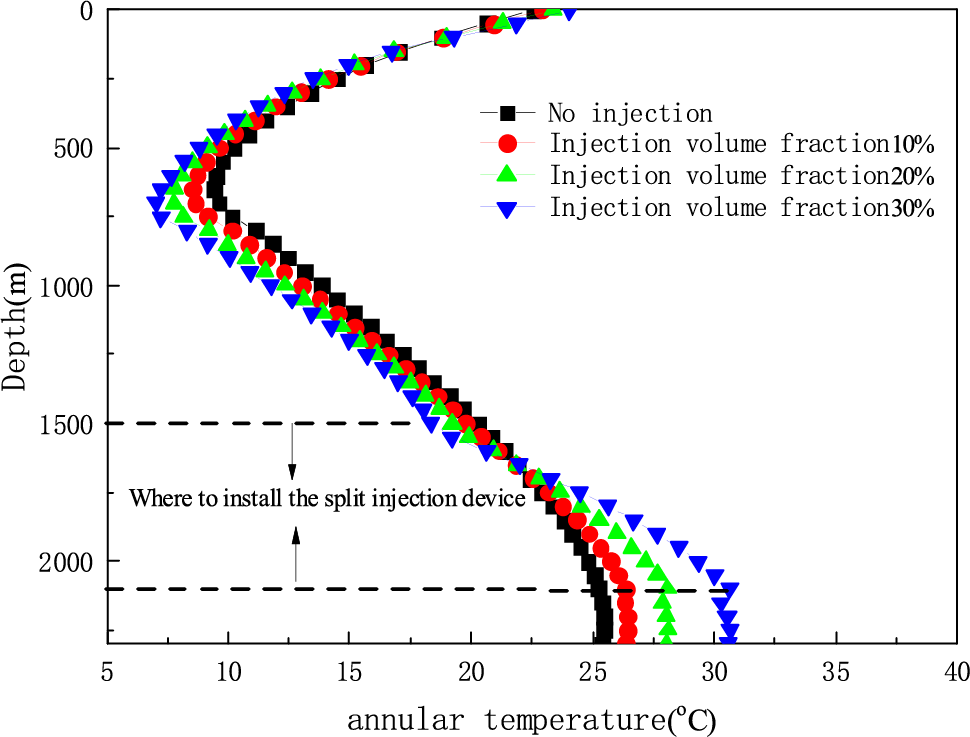
Figure 4: The effect of injected volume fraction of hollow spheres on the annulus temperature
In addition, the bottom hole temperature is higher than that without hollow sphere injection. In addition, with the increase of the injected volume fraction, the bottom hole temperature increases gradually. The reason is that the increases of the thermal conductivity of the wellbore mixed fluid. It leads to the heat exchange between the annular fluid and the formation sufficiently. Therefore, the larger the injection volume fraction of hollow spheres, the higher the temperature near the bottom hole of the annulus.
4.2 Influence of Device Separation Efficiency on Annular Temperature
In Fig. 5, we can get that with the decrease of the separation efficiency, the bottom hole temperature gradually increases. The reason is that with the decrease of the separation efficiency, the thermal conductivity of the fluid near the bottom of the annulus increases, the specific heat capacity decreases. Therefore, the heat exchange between the annular fluid and the formation is more sufficient. Therefore, the smaller the separation efficiency, the higher the bottom hole temperature. Moreover, at the same time the gas hydrate generation area in the annulus of the wellbore will be reduced (the part enclosed by the annulus temperature curve and the phase equilibrium temperature curve).
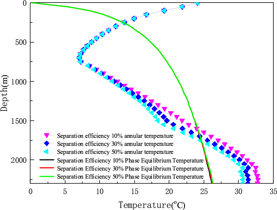
Figure 5: The effect of separation efficiency on annulus temperature when injection volume fraction is 30%
4.3 Influence of Device Installation Location on Annular Temperature
In Fig. 6, we can get that with the increase of the installation depth, the bottom hole temperature gradually decreases, while the wellhead temperature remains basically unchanged. It can greatly reduce the gas hydrate generation area in the wellbore. In addition, installation positions have a greater impact on the wellbore temperature. For example, compared with the first installation method, when the separator is installed at 1800 m, the drop rate of the annular temperature at the depth of 1200~1800 m is lower. The reason is that when the device is installed at 1800 m, there are the increase of thermal conductivity and the decrease of specific heat capacity. So, this change makes the temperature drop slower.
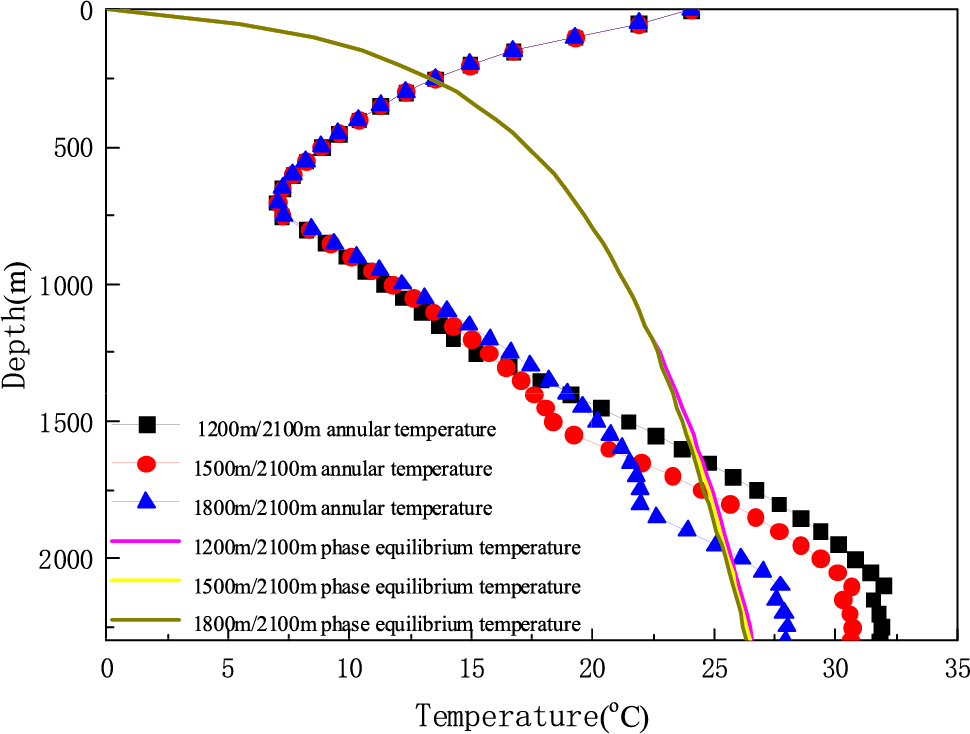
Figure 6: The effect of Installation position on annulus temperature when injection volume fraction is 30%
4.4 The Effect of Displacement on Annular Temperature
In Fig. 7, we can get that the larger the displacement, the lower the bottom hole temperature. The reason is that as the displacement increases, the heat exchange time between the fluid and the formation is less. It results in a decrease of the bottom hole temperature. At the same time, the temperature near the annulus wellhead remains basically unchanged. Therefore, the gas hydrate formation area will increase.
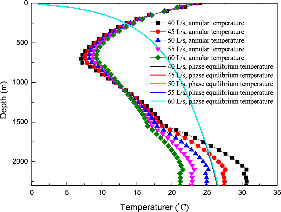
Figure 7: The effect of displacement on annulus temperature when injection volume fraction is 30%
(1) In this paper, a new heat transfer model was developed for multi-gradient drilling with hollow sphere injection. In this model, the characteristics of “variable mass” flow heat transfer and the change of fluid thermal physical parameters in the wellbore at the separation injection device are considered. In addition, the model solution process and stability judgment basis are given. It can provide theoretical guidance for the further study of multi-gradient drilling wellbore temperature field.
(2) At locations with the device, due to the inflow/outflow of the hollow spheres, the fluid heat at these positions and the thermophysical parameters of the annulus fluid have been changed. These eventually leads to a decrease in the temperature rise of the fluid in the drill pipe and the decrease in the temperature of the fluid in the annulus.
(3) In the multi-gradient drilling with hollow sphere injection, the lower separation efficiency of the device, the shallow installation depth and the small circulation displacement will increase the temperature near the bottom hole of the annulus, which will help to reduce the hydrate generation area. It forms a positive effect for hydrate prevention and control in deepwater drilling.
Acknowledgement: None.
Funding Statement: This research was funded by the Key Program of National Natural Science Foundation of China (Grant No. 51734010), and the Startup Fund of Changzhou University Science Research (Grant No. ZMF22020060).
Author Contributions: The authors confirm contribution to the paper as follows: study conception and design: Jiangshuai Wang, Jun Li; data collection: Hongwei Yang, Song Deng; analysis and interpretation of results: Jiangshuai Wang, Chuchu Cai, Pan Fu; draft manuscript preparation: Jiangshuai Wang, Pan Fu, Chuchu Cai, Jun Li. All authors reviewed the results and approved the final version of the manuscript.
Availability of Data and Materials: The data and materials that support the findings of this study are available on request from the corresponding author.
Conflicts of Interest: The authors declare that they have no conflicts of interest to report regarding the present study.
References
1. Smith, K. L., Gault, A. D., Witt, D. E., Weddle, C. E. (2001). Subsea MudLift drilling joint industry project: Delivering dual gradient drilling technology to industry. SPE Annual Technical Conference and Exhibition, 71357. https://doi.org/10.2118/71357-MS [Google Scholar] [CrossRef]
2. Wang, J. S., Li, J., Liu, G. H., Huang, T., Yang, H. W. (2019). Parameters optimization in deepwater dual-gradient drilling based on downhole separation. Petroleum Exploration and Development, 46(4), 819–825. [Google Scholar]
3. Wang, J. S., Li, J., Liu, G. H., Song, X. F. (2020). Development of a wellbore heat transfer model considering circulation loss. Arabian Journal of Geosciences, 13(2), 85. [Google Scholar]
4. Fossli, B., Sangesland, S. (2006). Controlled mud-cap drilling for subsea applications: Well-control challenges in deep waters. SPE Drilling & Completion, 21(2), 133–140. [Google Scholar]
5. Forrest, N., Bailey, T., Hannegan, D. (2001). Subsea equipment for deep water drilling using dual gradient mud system. SPE/IADC Drilling Conference, 67707. https://doi.org/10.2118/67707-MS [Google Scholar] [CrossRef]
6. Wang, J. S., Cai, C. C., Fu, P., Deng, S., Tang, Z. (2023). Study on simulation of cement plug-formation interface stripping failure and main influencing factors. Frontiers in Earth Science, 11, 1123620. [Google Scholar]
7. Lopes, C. (1997). Feasibility study on the reduction of hydrostatic pressure in a deep water riser using a gas lift method (Ph.D. Thesis). Louisiana State University, Baton Rouge, LA, USA. [Google Scholar]
8. Maurer, W. C., Medley, G. H., McDonald, W. J. (2003). Multi-gradient drilling method and system. U.S. Patent 006530437. [Google Scholar]
9. Yang, H. W., Li, J., Liu, G. H., Wang, J. S., Luo, K. D. et al. (2019). Development of transient heat transfer model for controlled gradient drilling. Applied Thermal Engineering, 148, 331–339. [Google Scholar]
10. Wang, Z. Y., Sun, B. J., Cheng, H. Q., Gao, Y. H. (2008). Prediction of gas hydrate formation region in the wellbore of deepwater drilling. Petroleum Exploration and Development, 35(6), 731–735. [Google Scholar]
11. RameyJr, H. J. (1962). Wellbore heat transmission. Journal of Petroleum Technology, 14(4), 427–435. [Google Scholar]
12. Sagar, R., Doty, D. R., Schmidt, Z. (1991). Predicting temperature profiles in a flowing well. SPE Production Engineering, 6(4), 441–448. [Google Scholar]
13. Ma, C. H., Wu, X. D., Shi, C. B. (2006). Theoretical study on heat pipe to improve temperature distribution of oil wellbore fluid. Chinese Journal of Petroleum, 1, 114–118. [Google Scholar]
14. Wang, J. S., Li, J., Liu, G. H., Liu, S. J., Ren, M. P. et al. (2021). Development and application of wellbore heat transfer model considering variable mass flow. Underground Space, 6(3), 316–328. [Google Scholar]
15. Zhang, G., Li, J., Yang, H. W., Liu, G. H., Pang, Q. et al. (2022). Simulation research on solid fluidization exploitation of deepwater superficial layer natural gas hydrate reservoirs based on double-layer continuous pipe. Journal of Natural Gas Science and Engineering, 108(5), 10428. [Google Scholar]
16. Yang, H. W., Li, J., Zhang, G., Zhang, H., Guo, B. Y. et al. (2022). Wellbore multiphase flow behaviors during gas invasion in deepwater downhole dual-gradient drilling based on oil-based drilling fluid. Energy Reports, 8(6), 2843–2858. [Google Scholar]
17. Yang, H. W., Li, J., Jiang, J. W., Zhang, H., Guo, B. Y. et al. (2022). A dynamic managed pressure well-control method for rapid treatment of gas kick in deepwater managed pressure drilling. Petroleum Science, 19(5), 2297–2313. [Google Scholar]
18. Yin, W., Lei, Y., Deng, S., Cui, M., Xu, S. K. et al. (2023). Temperature distribution of shale oil wellbore considering oil-based mud and formation fluid displacement. Journal of Dispersion Science and Technology. https://doi.org/10.1080/01932691.2023.2228397 [Google Scholar] [CrossRef]
19. Holmes, C. S., Swift, S. C. (1970). Calculation of circulating mud temperatures. Journal of Petroleum Technology, 22(6), 670–674. [Google Scholar]
20. Wang, L., Zhao, Y. S., Yang, D., Kang, Z. Q., Zhao, J. (2019). Effect of pyrolysis on oil shale using superheated steam: A case study on the Fushun oil shale, China. Fuel, 253, 1490–1498. [Google Scholar]
21. Wang, L., Yang, D., Kang, Z. Q. (2021). Evolution of permeability and mesostructure of oil shale exposed to high-temperature water vapor. Fuel, 290(3), 119786. [Google Scholar]
22. Li, B., Li, H., Guo, B. Y., Cai, X., Konggidinata, M. L. (2017). A new numerical solution to predict the temperature profile of gas-hydrate-well Drilling. SPE Journal, 22(4), 1201–1212. [Google Scholar]
Cite This Article
 Copyright © 2024 The Author(s). Published by Tech Science Press.
This work is licensed under a Creative Commons Attribution 4.0 International License , which permits unrestricted use, distribution, and reproduction in any medium, provided the original work is properly cited.
 Downloads
 Citation Tools