
 Submit a Paper
 Propose a Special lssue
 Open Access
ARTICLE

Optimizing the Diameter of Plugging Balls in Deep Shale Gas Wells
1 Shale Gas Research Institute, PetroChina Southwest Oil & Gasfield Company, Chengdu, 610056, China
2 State Key Laboratory of Oil & Gas Reservoir Geology and Exploitation, Southwest Petroleum University, Chengdu, 610500, China
3 National Pipe Network Group Sichuan East Natural Gas Transmission Pipeline Co., Ltd., Wuhan, 430205, China
4 Fracturing Acidizing Company, Downhole Operation Company of Chuanqing Drilling Engineering Co., Ltd., Chengdu, 610213, China
* Corresponding Author: Zheyu Hu. Email:
(This article belongs to the Special Issue: Solid, Fluid, and Thermal Dynamics in the Development of Unconventional Resources )
Fluid Dynamics & Materials Processing 2024, 20(3), 609-624. https://doi.org/10.32604/fdmp.2023.030521
Received 11 April 2023; Accepted 08 June 2023; Issue published 12 January 2024
 View Full Text
 Download PDF
Abstract
Deep shale gas reserves that have been fractured typically have many relatively close perforation holes. Due to the proximity of each fracture during the formation of the fracture network, there is significant stress interference, which results in uneven fracture propagation. It is common practice to use “balls” to temporarily plug fracture openings in order to lessen liquid intake and achieve uniform propagation in each cluster. In this study, a diameter optimization model is introduced for these plugging balls based on a multi-cluster fracture propagation model and a perforation dynamic abrasion model. This approach relies on proper consideration of the multiphase nature of the considered problem and the interaction force between the involved fluid and solid phases. Accordingly, it can take into account the behavior of the gradually changing hole diameter due to proppant continuous perforation erosion. Moreover, it can provide useful information about the fluid-dynamic behavior of the considered system before and after plugging. It is shown that when the diameter of the temporary plugging ball is 1.2 times that of the perforation hole, the perforation holes of each cluster can be effectively blocked.Graphic Abstract
Keywords
Nomenclature
| Ap | Particle projection area, m2 |
| C | Average concentration of the proppant, kg/m3 |
| CD | Particle traction coefficient |
| CL | Fracturing fluid loss coefficient, m/s0.5 |
| dp | Diameter of temporary plugging ball, m |
| dpf,i | Perforation diameter of cluster i, m |
| dw | Horizontal wellbore diameter, m |
| E | Young’s modulus, Pa |
| Fc | Collision contact force of the temporary plugging ball, N |
| Fdrag, i | Trailing force of the fluid phase on the temporary plugging ball i, N |
| FFP | Temporary plugging ball buoyancy, N |
| fblock,j | Probability of temporary plugging ball blocking perforation j |
| g | Gravity acceleration, m/s2 |
| hi(s,t) | Height at position s of the fracture i at time t, m |
| KIC | Fracture toughness of the formation rock, Pa·m0.5 |
| Ip, i | Rotational inertia moment of the plugging ball i, kg·m2 |
| Li(t) | Half-length of the fracture i at time t, m |
| Lw,j | Length of the horizontal well between cluster i and cluster i-1, m |
| Mblock,i | Number of perforations blocked in cluster i |
| Mdivert,i | Number of remaining plugging ball at the cluster i |
| Meffective,i | Number of remaining perforations at the cluster i |
| Mtotal | Total number of temporary plugging balls |
| mp, i | Mass of the temporary plugging ball i, kg |
| Ncl | Number of perforating clusters |
| Npf,i | Total number of perforating holes in cluster i |
| n | Number of particles contained in the control area |
| P | Fluid flow field pressure, Pa |
| pfi,i | Pressure in the first unit of fracture i, Pa |
| pheel | Horizontal well heel pressure, Pa |
| pi(s,t) | Fluid pressure at position s in the fracture i at time t, Pa |
| Qi(t) | Flow rate of the fracture i at time t, m3/min |
| QT | Fracturing rate, m3/min |
| qcl,i | Flow rate of cluster i, m3/s |
| qi(s,t) | Flow rate at position s in the fracture i at time t, m3/s |
| qL,i(s,t) | Fracturing fluid loss rate, m/s |
| qpf,j|j∈i | Flow rate of perforation hole j in cluster i, m3/s |
| qw,j | Flow rate downstream of perforation j, m3/s |
| qw,k | Flow rate between cluster i and cluster i-1, m3/s |
| Re | Reynolds number |
| Spl | Fluid and solid phase momentum exchange term |
| si | Length direction coordinates of the fracture i, m |
| Tc | Collision contact torque of the plugging ball, N·m |
| Tdrag, i | Trailing moment of the fluid on the plugging ball i, N·m |
| t | Fracturing time, s |
| U | Relative velocity of the fluid-solid phase, m/s |
| μ | Fracturing fluid viscosity, Pa·s |
| ▿V | Volume of the control area |
| VP | Temporary plugging ball volume, m3 |
| ν | Poisson’s ratio |
| vi | Perforation i hole flow rate, m/s |
| vl | Fluid velocity, m/s |
| vp | Particle velocity, m/s |
| vp, i | Linear velocity of the temporary plugging ball i, m/s |
| wi(s,t) | Width at position s of the fracture i at time t, m |
| wp, i | Angular velocity of the plugging ball i, rad/s |
| ▿x | Side lengths of the control area in the x direction |
| ▿y | Side lengths of the control area in the y direction |
| ▿z | Side lengths of the control area in the z direction |
| Greek symbols | |
| αpf | Hole flow coefficient, generally is 0.85 |
| Δppf,i | Frictional pressure drop at the perforation hole of cluster i, Pa |
| Δpw,j | Pressure drop between cluster i and cluster i-1, Pa |
| σh | Minimum horizontal principal stress, Pa |
| εl | Fluid-phase volume fraction |
| εs | Solid-phase volume fraction |
| ξdivert,j | Turning flow coefficient of perforation j, generally is 0-1 |
| ρl | Fluid density, kg/m3 |
| ρp | Temporary plugging ball density, kg/m3 |
| τi | Starting filtration time at position s of the fracture i, s |
| τl, τl′ | Stress under laminar and turbulent flow of the fluid phase, N/m2 |
The fracturing of deep shale gas horizontal wells is characterized by a large number of perforating clusters and small cluster spacing, which can increase the complexity of the high-pressure fracture network and expand the volume of the fracture network to a certain extent [1–3]. Although competition between different hydraulic fractures with different propagation speeds and lengths occurs because of the proximity of different hydraulic fractures during fracturing, this negatively impacts the fracture stimulation effect of deep shale gas horizontal wells [4,5]. For this reason, deep shale gas fracturing needs to be combined with the characteristics of temporary plugging diversion fracturing (TPDF) technology [6,7]. That is, the temporary plugging ball is pumped into the fracture wellbore during the fracturing process to block the perforating hole from excessive propagation fracture, reduce the inlet flow rate of fracture fluid at fractures, and slow down the propagation rate, and finally realize the goal of uniform propagation of each fracture.
At present, scholars have carried out relevant research on fluid-solid two-phase flow in horizontal wellbore and temporary plugging diversion fracturing. Patankar et al. [8] and Choi et al. [9] studied particle transport in fluids, analyzing the flow field of multiple circular particles and investigating the influence of Reynolds number and fluid viscosity on particle migration. They also proposed a correlation between the migration height of a single particle and its slip angular velocity. Acharya [10] studied the viscoelasticity of fluid and derived an expression for the settling velocity of individual particles. This expression can be used to predict the settling characteristics of particles in viscous fluids at intermediate Reynolds numbers. Xu et al. [11] employed a hybrid approach of discrete particle and computational fluid dynamics theory to simulate gas-solid two-phase flow, enabling the coupling of gas-solid phases across various length and time scales. By combining logging and microseismic monitoring, Cao et al. [12] and Chen [13] demonstrated that some temporary plugging balls could plug perforating holes while applying TPDF technology to the horizontal wells of the Rongwei Block and Mahu Field, respectively. Carpenter [14], Liang et al. [15], Fragachán et al. [16], and Zhang et al. [6] developed a mathematical model of the migration and block of temporary plugging ball in the wellbore. To analyze the impact of the number of temporary plugging balls, the time of temporary plugging, and the number of temporary plugging on the fracturing effect, Chen et al. [17], Nguyen et al. [18], and Cheng et al. [19] integrated the temporary plugging ball migration and settlement model with the fracture propagation model of the shale gas fracture network. They subsequently devised a series of optimization methods for temporary plugging ball parameters.
In summary, current research on the TPDF of horizontal wells primarily focuses on simulating hydraulic fracture propagation when temporary plugging balls block each cluster perforation hole. This study optimizes parameters like the number of temporary plugging balls, temporary plugging time, the number of temporary plugging occurrences, and temporary plugging displacement. However, it does not consider the gradual change in hole diameter caused by continuous proppant-induced perforation erosion during TPDF of deep shale gas horizontal wells. As a result, it is impossible to determine the diameter of each cluster perforation hole at the temporary plugging time, making it difficult to select a temporary plugging ball of the appropriate diameter to effectively plug the perforation hole. Consequently, the temporary plugging diversion design and process optimization of deep shale gas horizontal wells face challenges.
This study developed a mathematical model and numerical simulation method to optimize the diameter of temporary plugging balls for deep shale horizontal wells. The model is based on the principles of elasticity, fracture mechanics, fluid mechanics, and material balance. It considers various equations such as the fracture-flow equation, fracture width equation, fracture height equation, and flow distribution equation. The optimization aims to mitigate the continuous erosion effect on hole diameter caused by proppant injection. The findings of this study contribute to the improvement of fracture design for deep shale gas horizontal wells.
2 Temporary Plugging Ball Blocking Perforation Hole Model
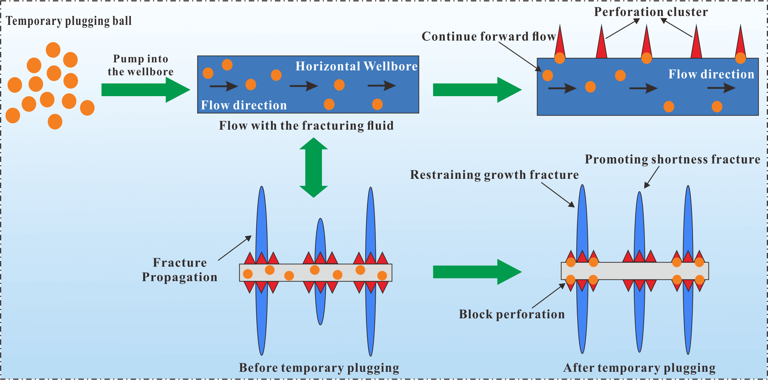
Several temporary plugging balls are typically pumped into the well during the process of temporary plugging multi-cluster fracturing at deep shale gas fractures to block the perforation of the partially divided clusters, restrain the dominant fractures’ excessive propagation, and promote the inferior fractures’ sufficient propagation, thereby realizing the regulation and control of the uniform propagation of each cluster fracture. While the fracturing fluid passes through the cluster perforation locations of the stage, the temporary plug ball is pumped. According to the flow distribution, whenever the temporary plugging ball passes through a cluster perforation, part of it will continue to flow ahead with the main flow, while the other part will flow toward the cluster perforation with the branch flow. Where the temporary plugging ball diameter is greater than the inner diameter of the perforation hole, then the temporary plugging ball blocks the perforation, as shown in Fig. 1.
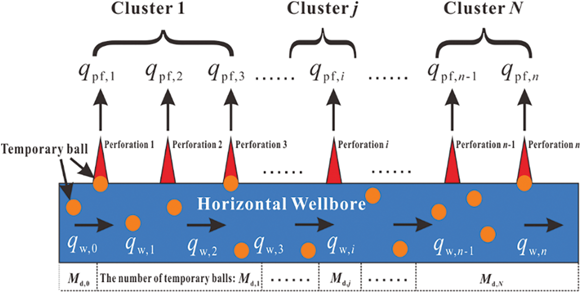
Figure 1: Temporary plugging ball blocking perforation mechanism
2.1 Control Equations for Two-Phase Flow
The temporary plugging ball is amalgamated with the fracturing fluid, creating a complex flow area. This interaction results in a certain degree of momentum exchange between the fluid and the temporary plugging ball. The fluid flow exerts a drag force on the temporary plugging ball, while concurrently, the temporary plugging ball phase imposes a counter-drag force on the fluid, altering the flow within the area. The control equations for the fluid-solid two-phase flow model comprise the fluid-phase control equations and the solid-phase motion equations, respectively.
2.1.1 Control Equations for Fluid Phase Flow
In the process of temporary plugging ball transportation, the complex interphase coupling of particles significantly influences the flow. This necessitates the consideration of the bidirectional coupling between fluid and particles. Consequently, it is essential to establish two-phase Navier–Stokes fluid flow control equations, which can depict the coupling term of fluid and solid phase. This involves the addition of the fluid volume fraction and two-phase interphase coupling term to the single-phase flow equations. Furthermore, the calculation of the fluid’s volume coefficient should account for the solid phase volume.
(1) Continuity equation
From the law of conservation of mass it follows that the difference in mass of the fluid entering and leaving the control body in a unit of time is equal to the incremental mass produced by the change in density of the fluid in the control body. From this, the fluid flow continuity equation can be derived as:
(2) Conservation of momentum equation
According to the momentum theorem, the change rate of fracturing fluid momentum and the sum of the mass force and surface force acting on the two-phase flow system are equal to each other.
2.1.2 Control Equations for Temporary Plugging Ball Motion
The process of temporary plugging ball motion is analyzed and resolved based on the discrete unit method within the Lagrangian framework. This process adheres to Newton’s second law. By employing the integral form of explicit advancement of the motion equations for the temporary plugging ball, we can determine the translational acceleration, velocity, angular velocity, angular acceleration, and position of the particles at any given moment. Particles in two-phase flows typically experience fluid drag forces, Saffman lift forces, virtual mass forces, pressure gradient forces, and gravity. This study focuses on the motion process of the temporary blocking ball. Given the high density of the temporary blocking ball, only gravity and drag force are taken into account, while other forces are deemed negligible due to their minimal impact.
The motion equation for the sloid-phase is:
2.1.3 Fluid and Solid Interaction Force
In the context of the fluid-solid two-phase flow model, a multitude of forces manifest between the fluid and solid phases. These encompass the drag force, pressure gradient force, Sommerfeld force, virtual mass force, Safman force, Basset force, and buoyancy force. In light of the insignificance of other forces, the drag force emerges as the fundamental agent governing momentum interchange between the fluid and solid phases. The influence of the solid phase can be accommodated through empirical or semi-empirical models.
The Di-Felice traction model [20] adds a porosity correction term to the Freestream traction model, which is able to take into account the drag effect generated between balls. Its calculation formula is:
χ is the coefficient, defined as:
Meanwhile, the Di-Felice traction model introduces a correction term for the particle volume fraction on the Gidaspow traction model, which makes it easier to converge in the numerical calculations for the solid phase.
The relative motion of the two phases makes the particles subject to the trailing force, and the coupling between the two phases of temporary plugging ball and fracturing fluid is achieved by adding the momentum exchange source phase S coefficient of the trailing force, which is calculated as:
Then:
The solid phase is subjected to fluid traction in addition to the above, and the fluid exerts a buoyant effect on the temporary plugging ball during injection of the fracturing fluid, calculated by the formula:
2.2 Multi-Cluster Fracture Propagation Model
The corresponding mathematical model is established based on the fracture propagation characteristics of the temporary plugging ball blocking the cluster, which mainly includes the plugging equation of the temporary plugging ball, the material balance equation, the flow equation in the fracture, and the flow rate distribution equation of multiple fractures.
2.2.1 Fluid Flow Equation in Fracture
Deep shale fracturing typically employs slippery water, which has Newtonian fluid properties and is incompressible. As a result, the fluid flow equation in hydraulic fractures is as follows:
2.2.2 Material Balance Equation in Fracture
According to the material balance principle, the material balance equation of a single hydraulic fracture propagation is:
Then:
2.2.3 Fracture Height and Width Equation
The hydraulic fracture height and width are closely related to the fracture toughness of the reservoir rocks and the pressure within the fractures. The expression is as follows:
2.2.4 Boundary and Initial Conditions for Fracture Propagation
The following are the initial and boundary conditions for the propagation of each hydraulic fracture cluster:
2.3 Temporary Plugging Ball Blocking Probability Model
2.3.1 Flow Distribution Equation of Each Perforation Cluster
When multiple hydraulic fractures begin and extend at the same time, the stress interference effect causes not only the fracture propagation to be diverted but also a significant difference in the flow rate of fracturing fluid at each fracture’s entrance. As a result, the flow distribution equation must be established to calculate the flow rate of each hydraulic fracture.
According to the principle of material balance, the global material conservation equation can be obtained:
Then, according to the equation of pressure drop along the path, N equations are obtained:
By combining the above formula, a set of nonlinear equations of N + 1 order can be obtained, and N + 1 unknowns can be solved by Newton iteration method (q1, q2, …, qn, pheel).
First, construct the following function:
Then the Jacobian matrix of the above nonlinear equations can be obtained from the constructor:
where
For the partial derivatives of the above equations, the Jacobian matrix elements can be written as:
After the Jacob matrix is constructed according to the above types, Newton iterative method can be used to solve the nonlinear equations of flow distribution. The iterative formula is as follows:
where
The initial value of the iteration can be assigned as:
Then, the flow distribution equation of each hole in the perforating cluster is:
2.3.2 Blocking Equation of Temporary Plugging Ball
The blocking perforation probability equation of the temporary plugging ball is given by:
The blocking quantity equation of the perforating cluster temporary plugging ball is as follows:
After the temporary plugging balls are pumped in during the fracturing process, the number of perforations in each cluster can be calculated, and the flow distribution equation can be used to determine the flow rate of each cluster fracture in the next step.
Then, it is necessary to construct the flow distribution equation after the temporary plugging ball blocking to calculate the flow rate of each perforation clusters.
Then the flow distribution equation for each hole in the perforation clusters at the next time step is:
The difference with the flow distribution before temporary plugging ball blocking is the reduction of the total number of perforations in the cluster i. As the pump flow rate is constant, the flow rate of single cluster increases, the force of fluid on the temporary plugging ball increases, the difficulty of turning the temporary plugging ball at the perforation increases, and the plugging probability increases, making it easier to plug the perforation hole.
2.3.3 Dynamic Perforating Hole Abrasion Equation
The perforation flow velocity equation is:
The perforating hole diameter equation is:
During the process of fracturing, under the condition of constant pumping flow rate, the perforation holes are constantly blocked by temporary plugging balls, the number of effective holes decreases, the flow rate of fluid entering a single hole increases, the dynamic abrasion strength of the holes increases, and the diameter of the holes continues to increase.
Finally, based on the change in the perforation hole diameter of each cluster over time, each cluster’s maximum perforation hole diameter was determined, and the obtained temporary plugging ball diameter was larger than 1.2 times the maximum perforation hole diameter of each cluster.
Combined with the schematic diagram of the simulation process in this paper, as shown in Fig. 2. It is totally and clearly explained how to optimize the temporary blocking ball’s diameter.
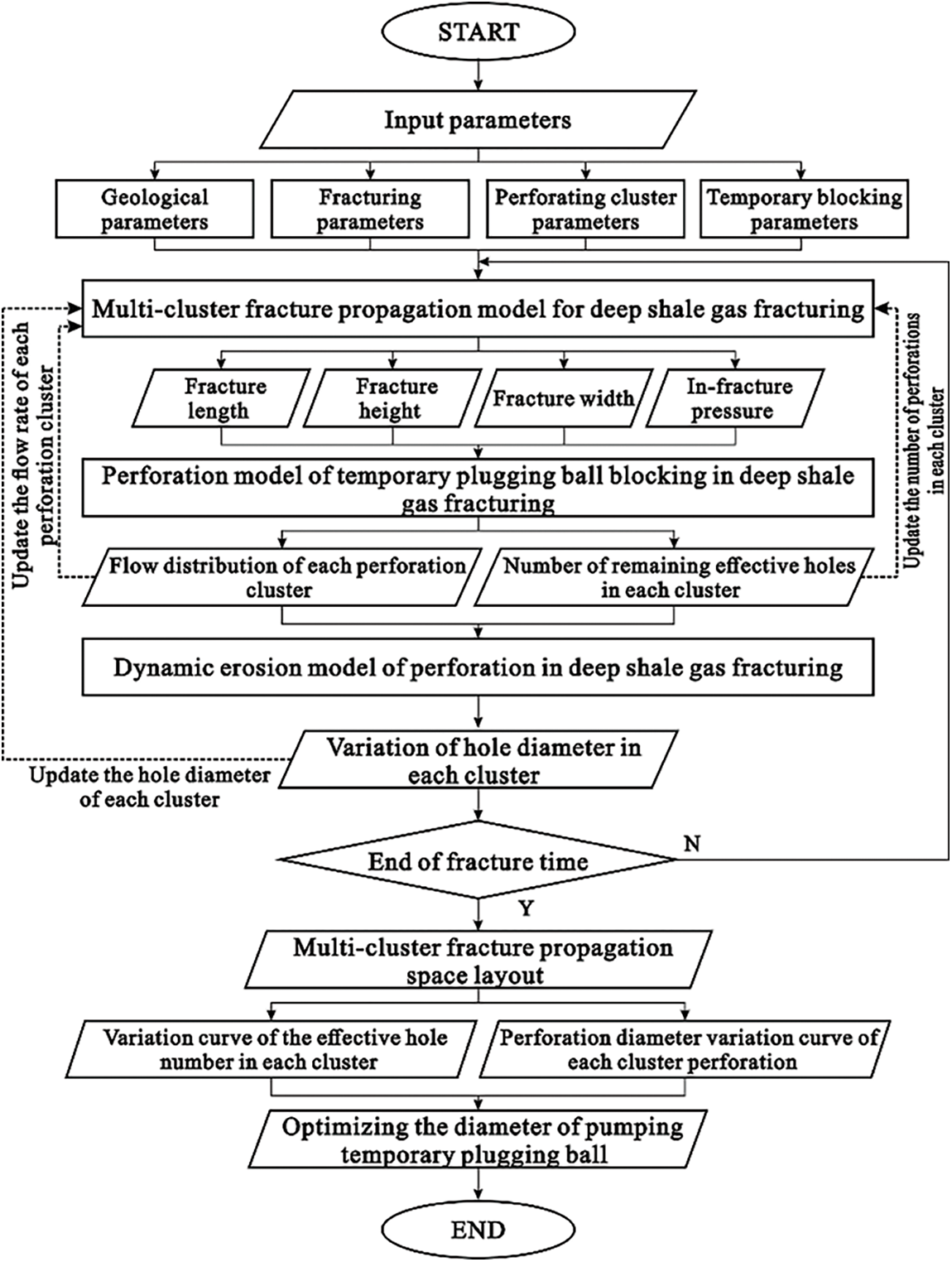
Figure 2: Simulation process schematic diagram of optimization temporary plugging ball diameter
We developed a simulation methodology to optimize the diameter of temporary plugging balls used in deep shale gas fracturing. This approach combines fluid-solid two-phase flow characteristics and utilizes the Newton iterative method to calculate the flow distribution, likelihood and number of temporary plugging ball blockages, and the count of remaining effective perforation holes during fracturing.
The number of perforations in each cluster and the flow rate of each fracture are updated as initial conditions for the calculation of the multi-cluster fracture extension model in the next time step. A differential equation is then used to determine the dynamic changes in the flow velocity and diameter of each perforation hole during the fracturing process. The hole diameter of each cluster perforation is updated, and the flow rate of each fracture in the next time step is calculated. Finally, based on the hole diameter of each cluster perforation over time, we determine the diameter of each cluster perforation at the time of pumping and optimize the diameter of the temporary plugging ball to ensure it is at least 1.2 times the maximum perforation diameter of each cluster.
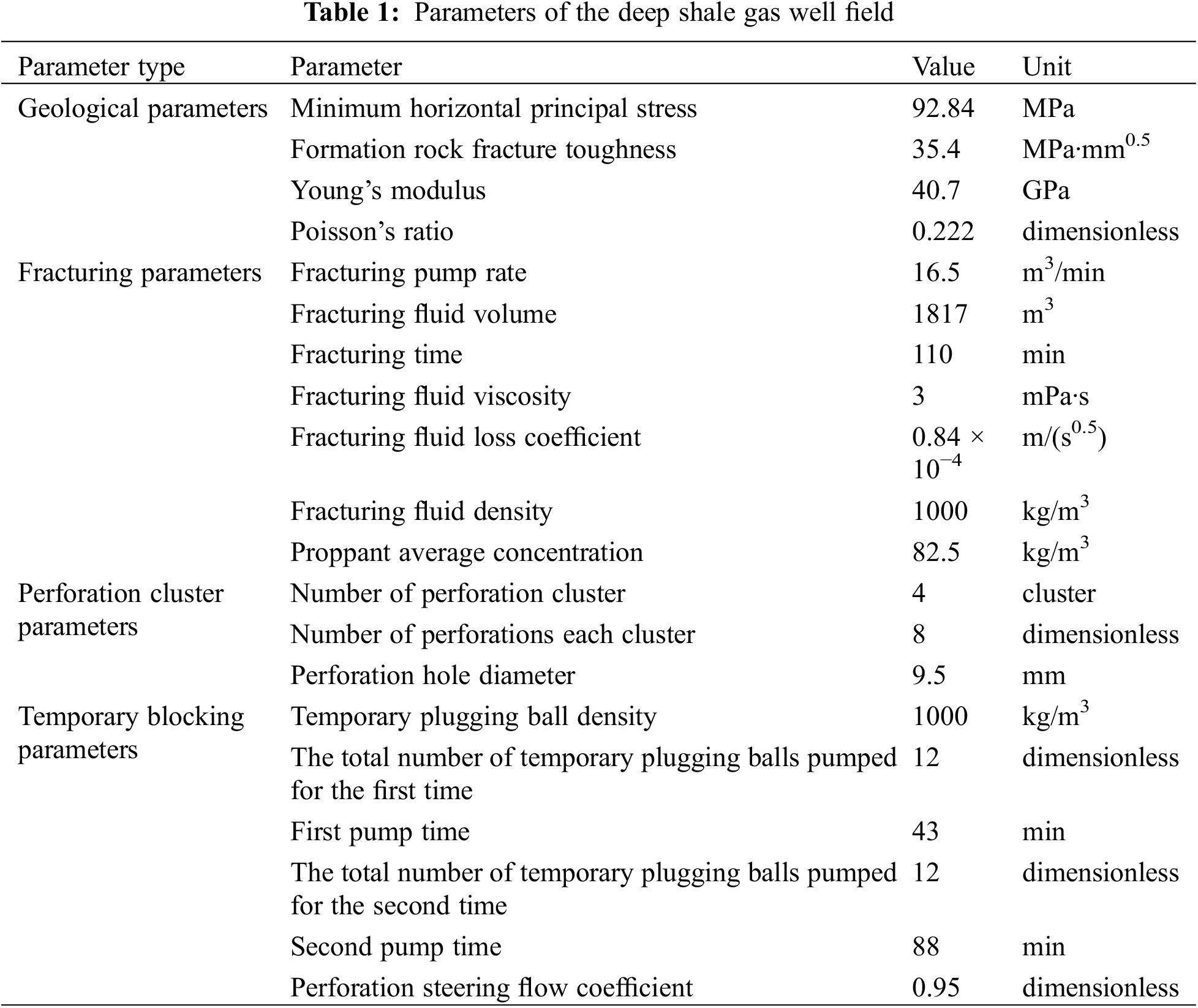
Based on the optimization model of the temporary plugging ball diameter for TPDF in deep shale gas horizontal wells, the matching of perforating cluster parameters and temporary plugging steering parameters and their effects were studied. Through the earlier discussed calculation methods and processes, and based on the parameters of a deep shale gas well, a horizontal well was assumed to be perforated in four clusters, with each cluster having eight perforations, and the optimization of the temporary plugging ball diameter under the influence of sustained proppant erosion on hole diameter was analyzed and discussed. The deep shale gas well parameters are presented in Table 1.
The simulation results show that 12 temporary plugging balls were pumped at 43 and 88 min respectively during the temporary plugging of diverting fracturing in deep shale gas horizontal wells. The number of effective perforations in each cluster gradually decreased as the temporary plugging time passed, indicating that the temporary plugging balls effectively plugged the perforations in each cluster, with cluster No. 1 and cluster No. 4 showing the more obvious effects. The number of effective holes was only one after the temporary plugging balls were pumped at the 88th min, as shown in Figs. 3 and 4.
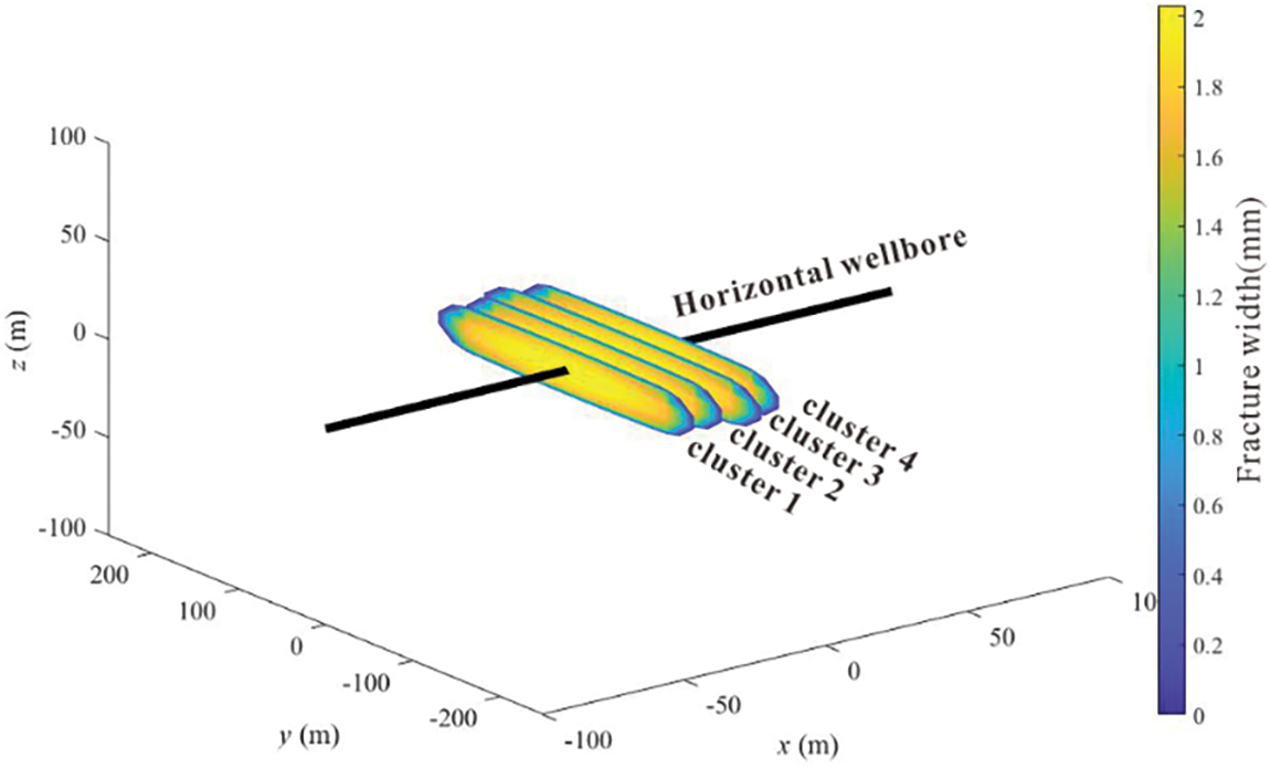
Figure 3: Propagation of multi-cluster fractures in deep shale gas horizontal wells
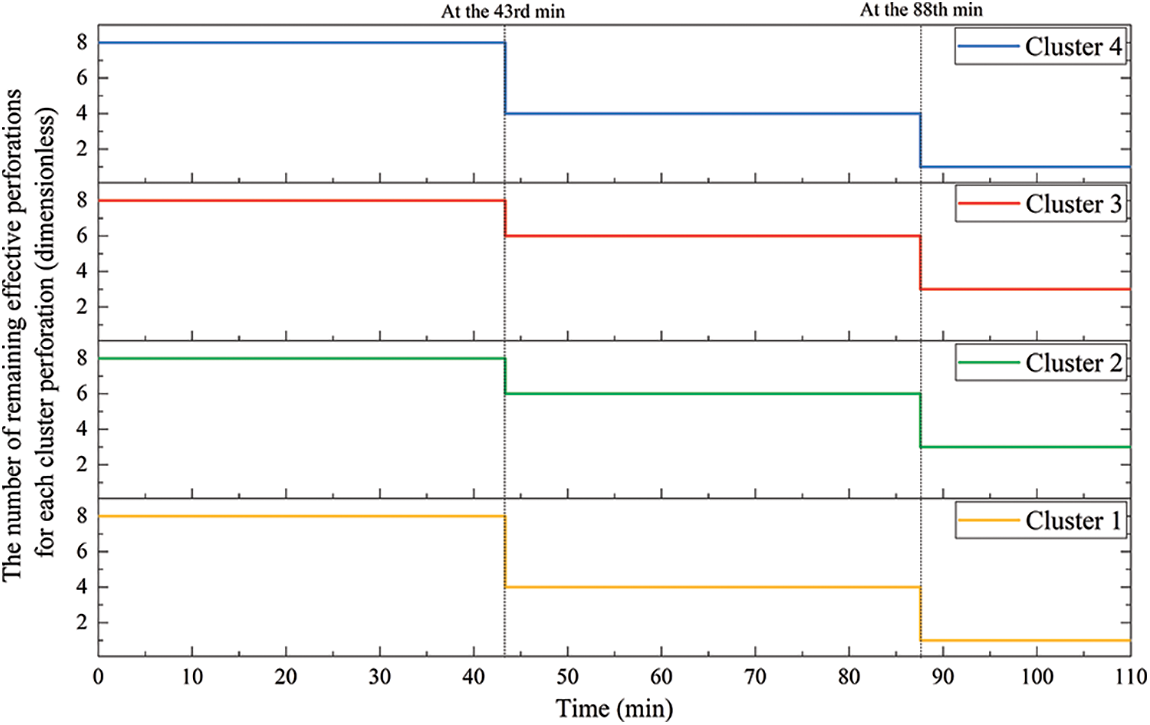
Figure 4: The changes in the number of effective perforations in each cluster with time
The simulation results show that the temporary plugging operation time increased the perforation diameter of each cluster. When the temporary plugging balls were pumped for the first time at the 43rd min, the perforation diameter of clusters No. 1 and No. 4 were the largest and were approximately 12.25 mm. When the temporary plugging balls were pumped for the second time at the 88th min, the perforation diameter of clusters No. 1 and No. 4 were approximately 14.82 mm, a 21% increase. As illustrated in Fig. 5. If it is necessary to plug each cluster of perforating holes, it is necessary to consider effective plugging. Therefore, the selection of temporary plugging ball diameters should retain a redundancy of 0.2 times, that is, 1.2 times the maximum diameter of the perforating hole.
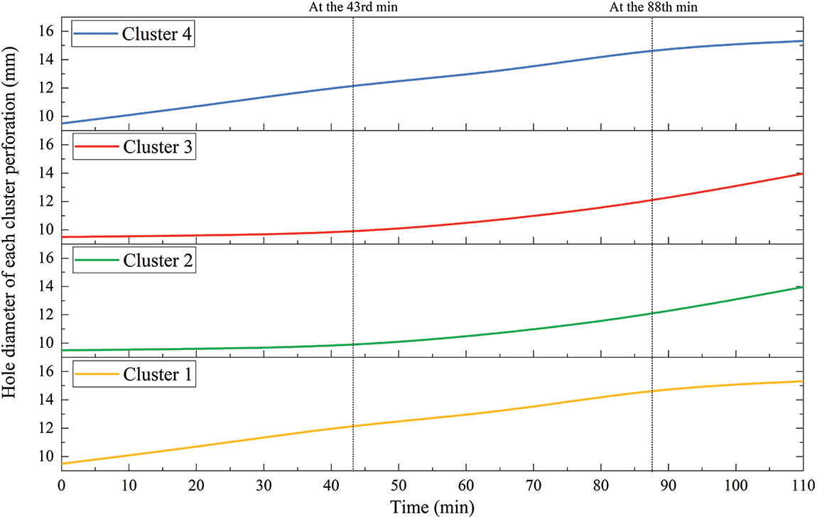
Figure 5: Perforation diameter of each cluster perforation changes with time
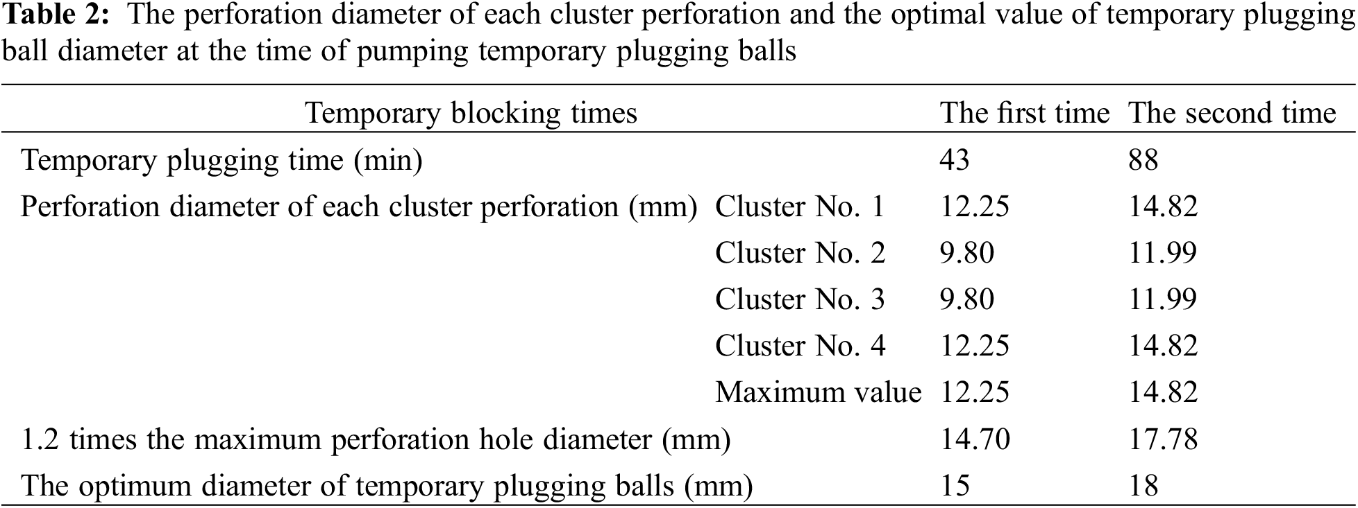
Table 2 shows the diameter of each cluster perforation hole when the temporary plugging balls were pumped. The maximum perforation hole diameters at the 43rd min for the first time and at the 88th min for the second time were 14.7 and 17.78 mm, respectively. Therefore, the selected temporary plugging ball diameters were 15 mm for the first pumping of 12 temporary plugging balls at 43 min and 18 mm for the second pumping of 12 temporary plugging balls at 88 min to achieve effective plugging of the perforating holes and promote the uniform propagation of each fracture.
This paper established the optimization model of temporary plugging ball diameter for the temporary plugging diverting fracturing of deep shale gas horizontal wells based on fluid-structure coupling theory, fluid mechanics, and frictional mechanics theory. The process parameters of temporary plugging diverting fracturing of field fractured wells were also optimized through numerical simulation, drawing the following conclusions:
(1) Field tests have shown that the diameters of multi-cluster perforation holes continue to increase under continuous proppant erosion. Effective plugging cannot be performed if the dynamic change of hole diameters is not considered, affecting the temporary plugging diverting fracturing effect.
(2) When the diameter of the temporary plugging ball is 1.2 times the perforation hole diameter at the pump time, the perforation holes of each cluster can be effectively blocked. The effective holes of each cluster can be changed from 8 holes in the original cluster to 3 holes or even 1 hole in the last cluster.
(3) To achieve effective plugging of perforating holes and promote the uniform propagation of each fracture, this model considers the behavior of gradually changing hole diameters caused by continuous proppant perforation erosion during the temporary plugging diverting fracturing. Appropriate temporary plugging ball diameters are selected based on the hole diameters at different times when the temporary plugging ball is pumped.
(4) In this paper, the model adopts the field implementation data, and the comparison of the field data confirms the accuracy of the model. The next step is to combine these with laboratory experiments to compare the dynamic changes of perforating perforations under continuous proppant erosion to enhance the reliability of the model.
Acknowledgement: None.
Funding Statement: This work was supported by the National Natural Science Foundation of China (No. U21B2071).
Author Contributions: The authors confirm contribution to the paper as follows: study conception and design: Yi Song, Lan Ren; data collection: Cheng Shen, Xingwu Guo, Kun Wang, Zhiyong Zhao; methodology: Ran Lin; analysis and interpretation of results: Zheyu Hu; draft manuscript preparation: Zheyu Hu. All authors reviewed the results and approved the final version of the manuscript.
Availability of Data and Materials: The data that support the findings of this study are available on request from the corresponding author. The data are not publicly available due to privacy or ethical restrictions.
Conflicts of Interest: The authors declare that they have no conflicts of interest to report regarding the present study.
References
1. Zhao, J. Z., Ren, L., Jiang, T. X., Hu, D. F., Wu, L. Z. et al. (2022). Ten years of gas shale fracturing in China. Review and Prospect. Natural Gas Industry B, 9(2), 158–175. https://doi.org/10.1016/j.ngib.2022.03.002 [Google Scholar] [CrossRef]
2. Olson, J. E. (2004). Predicting fracture swarms—The influence of subcritical fracture growth and the fracture-tip process zone on joint spacing in rock. Geological Society of London Special Publications, 231(1), 73–88. https://doi.org/10.1144/GSL.SP.2004.231.01.05 [Google Scholar] [CrossRef]
3. Hossain, M. M., Rahman, M. K. (2008). Numerical simulation of complex fracture growth during tight reservoir stimulation by hydraulic fracturing. Journal of Petroleum Science and Engineering, 60(2), 86–104. https://doi.org/10.1016/j.petrol.2007.05.007 [Google Scholar] [CrossRef]
4. Yong, R., Zhou, F. J., Li, M. H., Song, Y., Zhou, X. Y. et al. (2021). Effects of fracturing parameters on fracture unevenness during large-stage multi-cluster fracturing in horizontal wells. Frontiers in Energy Research, 9, 612486. [Google Scholar]
5. Manchanda, R., Mukul, M. S. (2013). Time-delayed fracturing: A new strategy in multi-stage, multi-well pad fracturing. Proceedings of the SPE Annual Technical Conference and Exhibition, New Orleans, Louisiana, USA. https://doi.org/10.2118/166489-MS [Google Scholar] [CrossRef]
6. Zhang, R., Hou, B., Tan, P., Muhadasi, Y., Fu, W. et al. (2020). Hydraulic fracture propagation behavior and diversion characteristic in shale formation by temporary plugging fracturing. Journal of Petroleum Science and Engineering, 190, 107063. https://doi.org/10.1016/j.petrol.2020.107063 [Google Scholar] [CrossRef]
7. King, G. E. (2010). Thirty years of gas shale fracturing: What have we learned? Proceedings of the SPE Annual Technical Conference and Exhibition, Florence, Italy. https://doi.org/10.2118/133456-MS [Google Scholar] [CrossRef]
8. Patankar, N. A., Huang, P. Y., Ko, T., Joseph, D. D. (2001). Lift-off of a single particle in Newtonian and viscoelastic fluids by direct numerical simulation. Journal of Fluid Mechanics, 438, 67–100. https://doi.org/10.1017/S0022112001004104 [Google Scholar] [CrossRef]
9. Choi, H. G., Joseph, D. D. (2001). Fluidization by lift of 300 circular particles in plane Poiseuille flow by direct numerical simulation. Journal of Fluid Mechanics, 438, 101–128. https://doi.org/10.1017/S0022112001004177 [Google Scholar] [CrossRef]
10. Acharya, A. R. (1986). Particle transport in viscous and viscoelastic fracturing fluids. SPE Production Engineering, 1(2), 104–110. https://doi.org/10.2118/13179-PA [Google Scholar] [CrossRef]
11. Xu, B. H., Yu, A. B. (1997). Numerical simulation of the gas-solid flow in a fluidized bed by combining discrete particle method with computational fluid dynamics. Chemical Engineering Science, 52(16), 2785–2809. https://doi.org/10.1016/S0009-2509(97)00081-X [Google Scholar] [CrossRef]
12. Cao, X., Wang, M., Kang, J., Wang, S., Liang, Y. (2020). Fracturing technologies of deep shale gas horizontal wells in the Weirong Block, southern Sichuan Basin. Natural Gas Industry B, 7(1), 64–70. https://doi.org/10.1016/j.ngib.2019.07.003 [Google Scholar] [CrossRef]
13. Chen, J. (2019). Application of temporary plugging stimulated reservoir volume fracturing in Mahu conglomerate tight oil. IOP Conference Series: Earth and Environmental Science, 237(4), 042035. [Google Scholar]
14. Carpenter, C. (2017). Enhancing well performance by in-stage diversion in unconventional wells. Journal of Petroleum Technology, 69(7), 70–72. https://doi.org/10.2118/0717-0070-JPT [Google Scholar] [CrossRef]
15. Liang, X., Zhu, J., Shi, X., Zhang, J., Liu, C. et al. (2017). Staged fracturing of horizontal shale gas wells with temporary plugging by sand filling. Natural Gas Industry B, 4(2), 134–140. https://doi.org/10.1016/j.ngib.2017.07.017 [Google Scholar] [CrossRef]
16. Fragachán, F. E., Shahri, M. P., Arnold, D. M., Babey, A. G., Smith, C. S. (2016). Enhancing well performance via in-stage diversion in unconventional wells: Physics and case studies. Prceedings of the SPE Argentina Exploration and Production of Unconventional Resources Symposium, Buenos Aires, Argentina. https://doi.org/10.2118/180985-MS [Google Scholar] [CrossRef]
17. Chen, M., Zhang, S., Zhou, T., Ma, X., Zou, Y. (2020). Optimization of in-stage diversion to promote uniform planar multi-fracture propagation: A numerical study. SPE Journal, 25(6), 3091–3110. https://doi.org/10.2118/201114-PA [Google Scholar] [CrossRef]
18. Thanh, T. N., Jean, S., Rawaz, D. M., Jean-Claude, D., Jean, C. et al. (2023). Experimental investigation of plugging and fracturing mechanisms inunconsolidated sand reservoirs under injection of water containing suspended fine particles. Geoenergy Science and Engineering, 221, 211346. https://doi.org/10.1016/j.geoen.2022.211346 [Google Scholar] [CrossRef]
19. Cheng, W., Lu, C., Feng, G., Xiao, B. (2021). Ball sealer tracking and seating of temporary plugging fracturing technology in the perforated casing of a horizontal well. Energy Exploration & Exploitation, 39(6), 2045–2061. https://doi.org/10.1177/01445987211020414 [Google Scholar] [CrossRef]
20. di Felice, R. (1994). The voidage function for fluid-particle interaction systems. International Journal of Multiphase Flow, 20(1), 153–159. https://doi.org/10.1016/0301-9322(94)90011-6 [Google Scholar] [CrossRef]
Cite This Article
 Copyright © 2024 The Author(s). Published by Tech Science Press.
This work is licensed under a Creative Commons Attribution 4.0 International License , which permits unrestricted use, distribution, and reproduction in any medium, provided the original work is properly cited.
 Downloads
 Citation Tools