
 Submit a Paper
 Propose a Special lssue
 Open Access
ARTICLE

Numerical Simulation of Droplet Generation in Coaxial Microchannels
School of Mechanical Engineering, Anhui Institute of Information Technology, Wuhu, 241100, China
* Corresponding Author: Zongjun Yin. Email:
Fluid Dynamics & Materials Processing 2024, 20(3), 487-504. https://doi.org/10.32604/fdmp.2023.042631
Received 06 June 2023; Accepted 05 September 2023; Issue published 12 January 2024
 View Full Text
 Download PDF
Abstract
In this study, numerical simulations of the pinching-off phenomena displayed by the dispersed phase in a continuous phase have been conducted using COMSOL Multiphysics (level-set method). Four flow patterns, namely “drop flow”, “jet flow”, “squeeze flow”, and “co-flow”, have been obtained for different flow velocity ratios, channel diameter ratios, density ratios, viscosity ratios, and surface tension. The flow pattern map of two-phase flow in coaxial microchannels has been obtained accordingly, and the associated droplet generation process has been critically discussed considering the related frequency, diameter, and pinch-off length. In particular, it is shown that the larger the flow velocity ratio, the smaller the diameter of generated droplets and the shorter the pinch-off length. The pinch-off length of a droplet is influenced by the channel diameter ratio and density ratio. The changes in viscosity ratio have a negligible influence on the droplet generation pinching frequency. With an increase in surface tension, the frequency of generation and pinch-off length of droplets decrease, but for small surface tension the generation diameter of droplet increases.Graphic Abstract
Keywords
Nomenclature
| Cac | Capillary number Cac = μcuc/σ |
| D | Diameter of droplet generation |
| Dc | Diameter of continuous phase inlet |
| dd | Diameter of dispersed phase inlet |
| Fst | Surface force |
| Fθ | Boundary force |
| F | Frequency of droplet generation |
| g | Gravitational acceleration |
| I | Identity matrix |
| K | Viscous stress tensor |
| Knt | Tangential stress |
| L | Pinch-off length of droplet generation |
| Lc | Length of continuous phase channel |
| Ld | Length of dispersed phase channel |
| nint | Normal direction of interface |
| t | Time |
| uslip | Slip velocity |
| nwall | Normal unit vector of the wall |
| p | Pressure of the mixed fluid |
| β | Slip length |
| γ | Reinitializing parameter |
| δ | Viscosity ratio δ = μd/μc |
| δd | Dirac function |
| εls | Thickness controlling parameter |
| η | Flow velocity ratio η = ud/uc |
| θw | Contact angle |
| λ | Channel diameter ratio λ = dc/dd |
| μ | Density of the mixed fluid |
| μc | Density of the continuous phase |
| μd | Density of the dispersed phase |
| ρ | Density of the mixed fluid |
| | Density of the continuous phase |
| | Density of the dispersed phase |
| σ | Surface tension coefficient |
| | Level set function |
| | Density ratio |
Microfluidic chips can achieve environmental detection, drug screening, and real-time disease diagnosis on a tiny chip by manipulating a tiny amount of liquid [1,2]. Microfluidic chips have such advantages as low sample consumption, high analysis speed, high throughput, miniaturization, and portability [3,4]. The increasing maturity and abundance of droplet microfluidic applications have led to new requirements for droplet preparation technology, mainly including the preparation of mono-disperse droplets with high throughput [5] and the complexity of droplet composition structure [6].
Microfluidics can be divided into passive microfluidics and active microfluidics [7]. Passive microfluidic control can be used to complete various reactions through the capillary action of the liquid itself without any external force. Active microfluidics uses external driving forces (including electrical wetting, surface waves, and magnetic forces) for microfluidic manipulation. Passive microfluidics include the multiphase flow method [8], and the concentration gradient method [9]. The multiphase flow method utilizes shear force, viscosity, and surface tension to generate velocity differences by designing microchannels and controlling fluid flow rates, thereby splitting the liquid flow into microdroplets. The concentration gradient method obtains a complex series of concentration gradients by forming precise concentration gradients and changing the configuration design of the network channels. Active microfluidics include the centrifugal method [10], the thermal capillary method [11], the electrowetting-on-dielectric (EWOD) method [12], the pneumatic method [13], the electric wetting method [14] and the magnetic method [15]. The centrifugal method utilizes centrifugal force to generate a velocity difference, dispersing the fluid into different channels for reactions. The thermal capillary method operates on the fluid by locally heating the fluid to create a thermal gradient and changing the local surface energy of the fluid. The EWOD method applies voltage at both ends of the channel to make the liquid flow in the channel generate electroosmotic force. The pneumatic method uses gas pressure (positive or negative pressure) as the shear and driving force to drive the liquid flow movement. The electrical wetting method alters the wetting characteristics of the liquid through an array of microelectrodes under the surface of the chip, creating a pressure difference within the droplet, which allows for precise droplet manipulation. The magnetic method applies a magnetic field locally to the chip to generate magnetic propulsion, which pushes magnetic beads, or a suspension containing magnetic beads to squeeze the microchannel space and cause the fluid to move.
T-channel, flow focusing, and coaxial flow focusing are three simple forms of the multiphase flow method [16,17]. In recent years, many scholars have conducted research on droplet preparation using various channel structures based on the multiphase flow method. In the T-channel form, two immiscible fluids meet at the intersection of a vertical T-shaped pipeline, and under the action of pressure and shear force, the continuous phase truncates the dispersed phase, forming droplets. In the flow focusing form, three flow paths are focused in a pipeline, where the dispersed phase and the continuous phase converge at the cross pipe. The dispersed phase is squeezed to break, forming droplets. In the coaxial flow focusing form, the dispersed phase and continuous phase flow in parallel in the pipeline. When the dispersed phase enters the continuous phase pipeline, it is squeezed and fractured to form droplets under the shear force of the continuous phase fluid. Tang et al. [18] observed the diffusion rate and size of dielectric droplets under distinct driving voltages and conductive microchannels. Majnis et al. [19] prepared polydimethylsiloxane (PDMS) microchannels using photolithography, and observed squeeze and drop flow patterns. Hirama et al. [20] prepared various aqueous and organic droplets using glass microchannels. Pang et al. [21] found that the deformation of the soft wall was able to reduce the dispersion of droplet size. Yan et al. [22] studied the kinetic properties of water droplets and considered the effect of microchannel size behavior parameters. Zhang et al. [23] found that necked microchannels can produce droplets with smaller diameters and faster frequencies than other double-T microchannels. Jing et al. [24] observed droplet flow and plug flow in a reverse flow T-shaped microchannel. Hsiung et al. [25] made a new controllable microfluidic chip producing uniform emulsion droplets. Marculescu et al. [26] studied the variation of the inlet flow ratio for different capillary numbers. Yan et al. [27] observed different flow patterns, including long segment plug flow, small spherical flow, steady flow, and parallel flow, and found that the pressure amplitudes of droplet, squeeze, jet, and parallel flow types decreased sequentially at different flow rates. Sivasamy et al. [28] increased the residence time of droplets in the T-tube, enhancing the droplet coalescence. Li et al. [29] verified that the accumulation of upstream pressure favors the formation of long-segmented plugs. Han et al. [30] investigated the effect of geometric configuration on droplet merging in double T-shaped structured microchannels. Chen et al. [31] investigated the serpentine microchannel, involving square wave, multi-wave, and zigzag. Yang et al. [32] studied the fluid dynamics and mixing processes of droplets in T-shaped microchannels and sinusoidal microchannels. Gidde et al. [33] performed numerical simulations of the micro-mixer and investigated the effect of Reynolds number Re. Zhu et al. [34] explored the occurrence of droplet breakup in the cross-flow, co-flow, flow focusing, and step emulsion structure.
However, the mechanisms regulating the generation and evolution of droplet flow patterns with respect to the two-phase physical parameters in coaxial microchannels are still unclear, and the quantitative influence laws on droplet generation still need to be further elucidated. In this paper, four flow patterns of oil droplets in coaxial microchannels were simulated by COMSOL Multiphysics software, namely drop flow, jet flow, squeeze flow, and co-flow, and the pinch-off mechanisms of drop flow and jet flow were interpreted. The effects of flow velocity ratio, channel diameter ratio, density ratio, viscosity ratio, and surface tension on droplet generation characteristics are also analyzed.
The Level Set method was first proposed by mathematicians Osher et al., and subsequently, it has been applied to fluid mechanics, material science, and other fields [35]. Because the Level Set method applies a smooth distance function
where u denotes the velocity field of the flow field, γ expresses the reinitializing parameter, εls is the interface thickness controlling parameter. The Level Set method does not require reconstructing the interface, but treats the phase interface as an iso-surface of the smooth and continuous Level Set function
In the dynamic process of droplet generation, the oil/water two phases are incompressible Newtonian fluids, the flow of dispersed phase and continuous phase are considered as laminar flow, and the whole system is adiabatic. Therefore, the governing equations for viscous incompressible fluids are as follows:
where, ρ, μ, and p are the density, viscosity, and pressure of the mixed fluid; I denotes the identity matrix; Fst is the surface force; and g is the gravitational acceleration. The density and viscosity of the mixed fluid in the flow field are calculated as follows:
where,
Surface tension is the force acting on the interface of two phases along the surface of a droplet due to the imbalanced molecular attraction. The level set method introduces surface tension into the source term of the N-S equation:
where,
in which, σ represents the surface tension coefficient, nint denotes the normal direction of the liquid-liquid interface, δd is the Dirac function.
On the boundary of a solid wall, the velocity of the fluid is different from that of the solid wall, resulting in slip velocity. Therefore, the wall meets the condition of no permeability:
where, nwall is the normal unit vector of the wall. The tangential stress Knt and slip velocity uslip of fluid at the wall are:
where, Knt = Kn − ( Kn ⋅ nwall) nwall, Kn = Knwall, K = (∇u + ∇uT), K is the viscous stress tensor, and β is the slip length. For walls in contact with the fluid-fluid interface, a boundary force Fθ is also applied to enforce the contact angle θw:
The boundary conditions for ϕ(x,t) on the open boundary (including inlet and outlet) and wall are:
where,
2.2 Solution of Finite Element Method
COMSOL Multiphysics is a computing platform that converts mathematical models into computer simulations. By Discretization, the continuous geometric modeling is divided into several grid elements, thus a matrix problem can be obtained, and various partial differential equations can be solved based on finite element method. In the COMSOL Multiphysics, partial differential equations are transformed into weak forms, and boundary conditions are also transformed into corresponding weak constraints. The integral form is known to be particularly suitable for finite element methods because it circumvents the discontinuity of the integral variables. The weak form is an integral form, but it requires less continuity of the integration variables and is well suited for solving nonlinear multi-physics field problems. When performing finite element calculations in COMSOL Multiphysics, the software always automatically transforms the control equations into their weak form first, and then constructs a set of finite element equations for calculation. By grid partitioning, a set of algebraic equations is obtained by the Galerkin method [36]. Finally, the approximate solutions of these equations at the grid vertices are obtained by solving the algebraic equations, and then the solutions at any point inside the grid element can be obtained by the interpolation method.
The weak forms of Eqs. (1), (3), and (4) can be written in the following forms [37]:
where, V is the bulk of computational domain, Γ means the boundary of computational domain,
where, k and g are known coefficient parameters, ψ is a test function, U is the dependent solution variable (i.e., velocity u, Level Set function ϕ, pressure p, etc.). The numerical equation is constructed by the weak form, which means that the solution of the numerical equation is the approximate solution of the corresponding control equation.
Assuming that the approximate solution can be represented as a linear combination of a set of basis functions ψi, the variable U can be expressed in the following form:
where, Ui is is the value of U at grid node i. Thus, the discretization form of Eq. (19) becomes:
Once boundary conditions are applied, Eq. (14) can be further represented in the following form:
where U = ( u, p,
The process of generation of oil droplets in coaxial microchannels is a transient process. As shown in Fig. 1, the coaxial microchannel includes a main channel with a diameter of dc = 0.12−0.36 mm (continuous phase inlet) and a branch channel with a diameter of dd = 0.03–0.06 mm (dispersed phase inlet). The length of the continuous phase channel is Lc = 3 mm, and the length of the dispersed phase channel is Ld = 0.5 mm. The inlet of the continuous phase and the dispersed phase are both velocity inlet boundary conditions, and the outlet is pressure outlet boundary condition. The wall of the channel has a non-slip boundary condition. At the initial moment, the two-phase fluids remain stationary at a pressure of 1 atm.
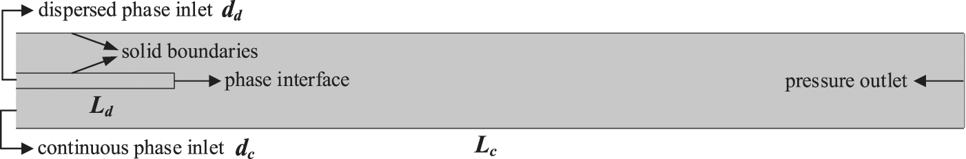
Figure 1: Structure of the coaxial microchannels
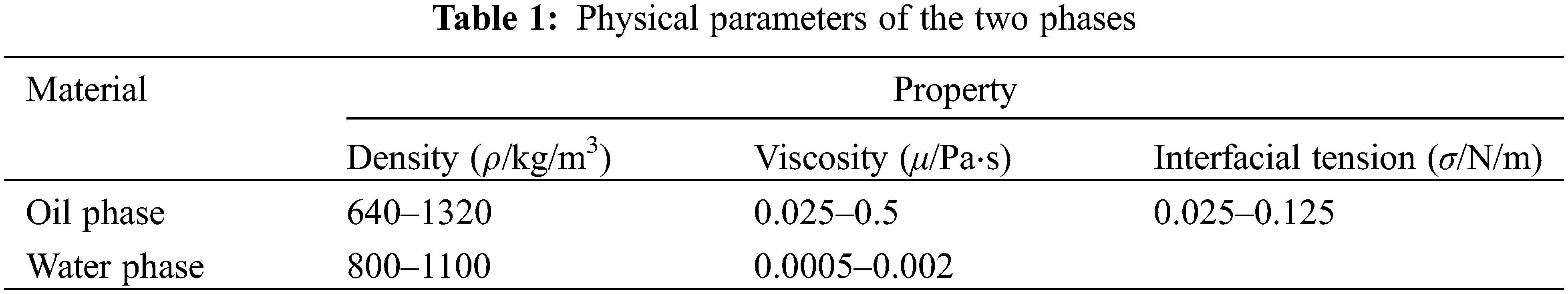
The generation of droplets on microfluidic chips involves the separation of two immiscible liquids, one as a continuous phase and the other as a dispersed phase. The dispersed phase is dispersed in the form of small volume units in the continuous phase, forming droplets. According to the difference between dispersed and continuous phases, droplets can be divided into two types: water-in-oil (W/O) type droplets and oil-in-water (O/W) type droplets. Specifically, the W/O type droplets consider water phase as the dispersed phase and oil phase as the continuous phase, while the O/W type is the opposite. Our study only refers to the O/W fluid droplets, where the water phase refers to various aqueous solutions in general and the oil phase is an organic solvent that is insoluble in water. The water phase and oil phase simultaneously flow into the microchannels from the different entrances. The walls of the channels are oleophobic, while the water phase can infiltrate the channels and encapsulate the oil phase, forming O/W-type droplets. Table 1 provides the range of values for the two-phase physical parameters.
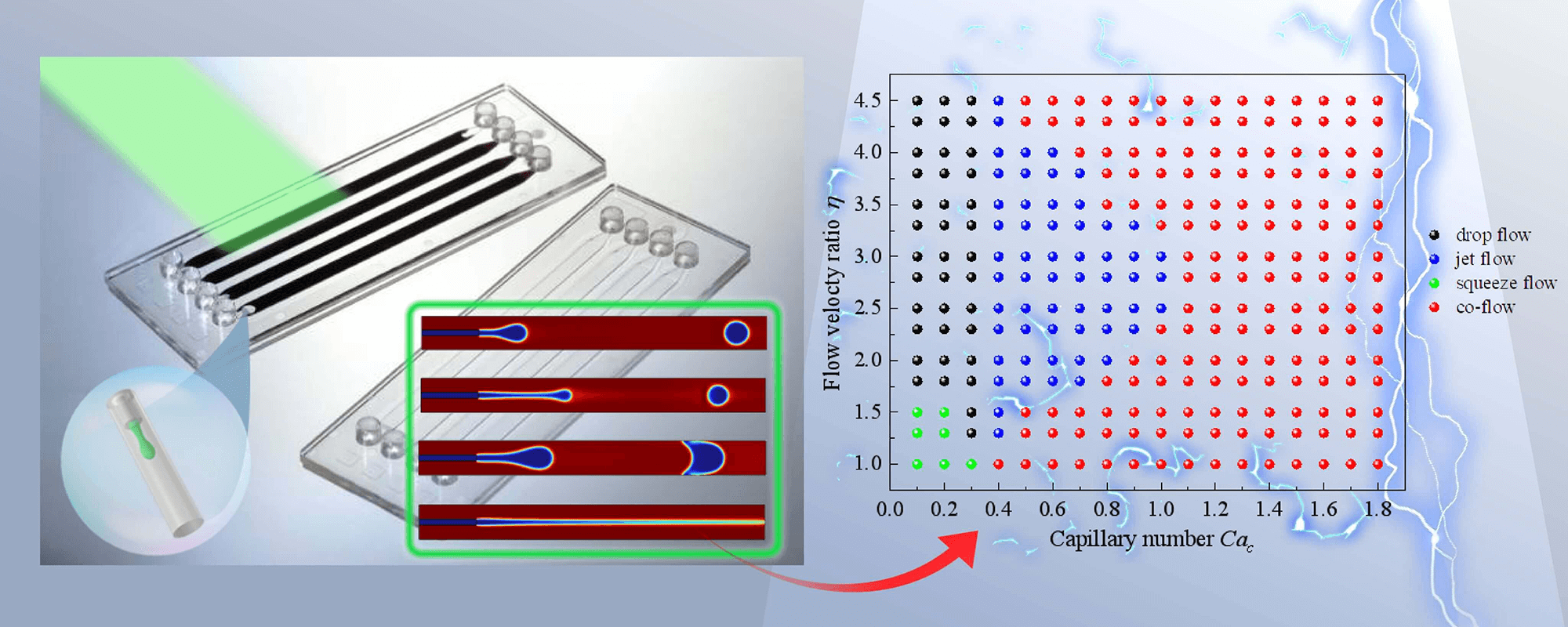
The formation of liquid droplets is due to the combined action of the surface tension and shear force of the water/oil two phases. The flow pattern of droplet generation is strongly influenced by the flow velocity ratio between the two phases η = ud/uc (ud and uc are the flow velocities of the dispersed and continuous phases), and the capillary number of the dispersed phase Cac = μcuc/σ (μc is the viscosity of the continuous phase, σ is the interfacial tension coefficient between the two phases). Changing the flow velocity ratio of the oil and water phases can change the relative magnitude of the surface tension and shear force, resulting in different flow patterns.
The dynamic characteristics of droplet formation can be described using the frequency f, diameter d, and the pinch-off length L of droplet generation. As shown in Fig. 2a, the pinch-off length L is defined as the distance from the head of the droplet to the tail of the liquid bridge when a complete droplet is just generated. Fig. 2b shows the variation of flow streamline l with time t in a drop flow pattern, in which the frequency f and the pinch-off length L of droplet generation can be identified.
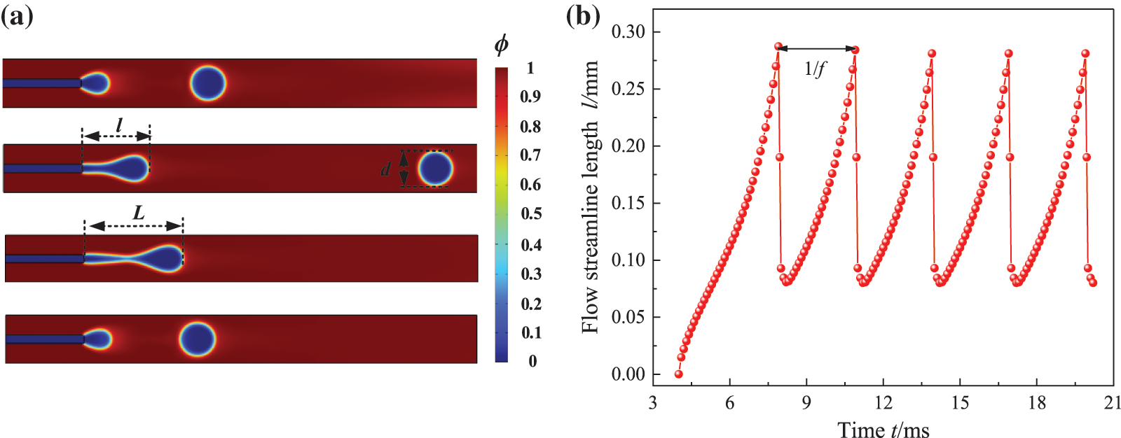
Figure 2: Definition of parameters; (a) geometric configuration; (b) the evolution of flow streamline l over time t for case η = 2.4 and Cac = 0.28
2.5 Verification of Grid Independence
The quantity and quality of grids are crucial for simulating the flow state of oil droplets. The purpose of grid independence verification is to eliminate the effect of grid on the calculation results in the balance between numerical accuracy and computational cost.
As shown in Fig. 3a, the structured grid was used to disperse the flow field considering the regular geometric characteristics of the flow field. Due to the jump in physical variables of the two-phase flow, boundary layer grids were used to refine solid boundaries and phase interfaces. The grid-independence of the oil droplet generation process was verified by using five different grid quantities for the dispersed phase flow velocity ud = 0.294 m/s and flow velocity ratio η = 2.1. In addition, the channel width dd = 0.03 mm, channel width ratio λ = dc/dd = 6, continuous phase viscosity μd = 0.001 Pa⋅s, viscosity ratio δ = μd/μc = 100, continuous phase density
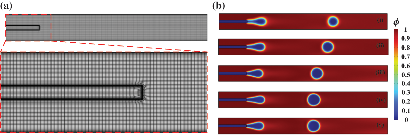
Figure 3: Verification of grid independence; (a) grid partition when the quantity of grid elements is Γ = 35619; (b) comparison of calculation results at t = 0.02 for five different grids (i) Γ = 15752, (ii) 19256, (iii) 22481, (iv) 35619, and (v) 89596
As depicted in Fig. 3b, there is a spurious flow when the quantity of grid elements is Γ = 15752, 19256, and 22481. The spurious flow refers to the phenomenon of velocity anomalies caused by velocity calculation errors in the numerical solution process of two-phase flow. The accuracy of the calculation depends on the quality of the grid, and the finer the grid, the higher the accuracy. When the quantity of grids is Γ = 35619 and 89596, the position of the oil droplets tends to be more precise in fluid flow. To eliminate the sensitivity of calculation results caused by grid variation, the grid quantity Γ = 35619 is applied to generate computational nodes for the flow field.
2.6 Comparison with Experiments
Lan et al. [40] experimentally investigated the liquid-liquid two-phase flow in a coaxial microchannel. Wang et al. [41] studied the breakup-mechanism of nanowires, which provide an alternative insight for the generation of droplets. Wang et al. [42] argued for a breakup transition from a continuous phase via dispersed particles towards a uniform-radius cylinder and described Plateau-Rayleigh’s criterion. To further verify the accuracy of the simulation algorithm, the Level Set simulations were compared with Lan’s work on droplet generation characteristics in coaxial microchannels.
As shown in Fig. 4a, in the drop flow regime, a concave neck (t = 141 ms) appeared at the interface between the continuous and dispersed phases downstream of the channel intersection. As the fluid in the dispersed phase continuously flowed into the continuous phase, the neck was continuously stretched. After the neck fracture, the ellipsoidal droplets rapidly became spherical under the action of interfacial tension (t = 163 ms). As shown in Fig. 4b, in the jet flow regime, a small rim (t = 45 ms) was maintained at the top of the jet line. As the dispersed phase was continuously injected, the jet line gradually elongated (t = 55 ms) and the rim also increased. The jet extended further downstream of the channel intersection (t = 59 ms), and the slender jet was not enough to drag the rim, causing the jet line to break and droplets to form. Fig. 4 shows good consistency between the calculated results and the experimental results. The simulation results remarkably reflected the experimental results, and also verified the reliability of the Level Set method in interface capture.
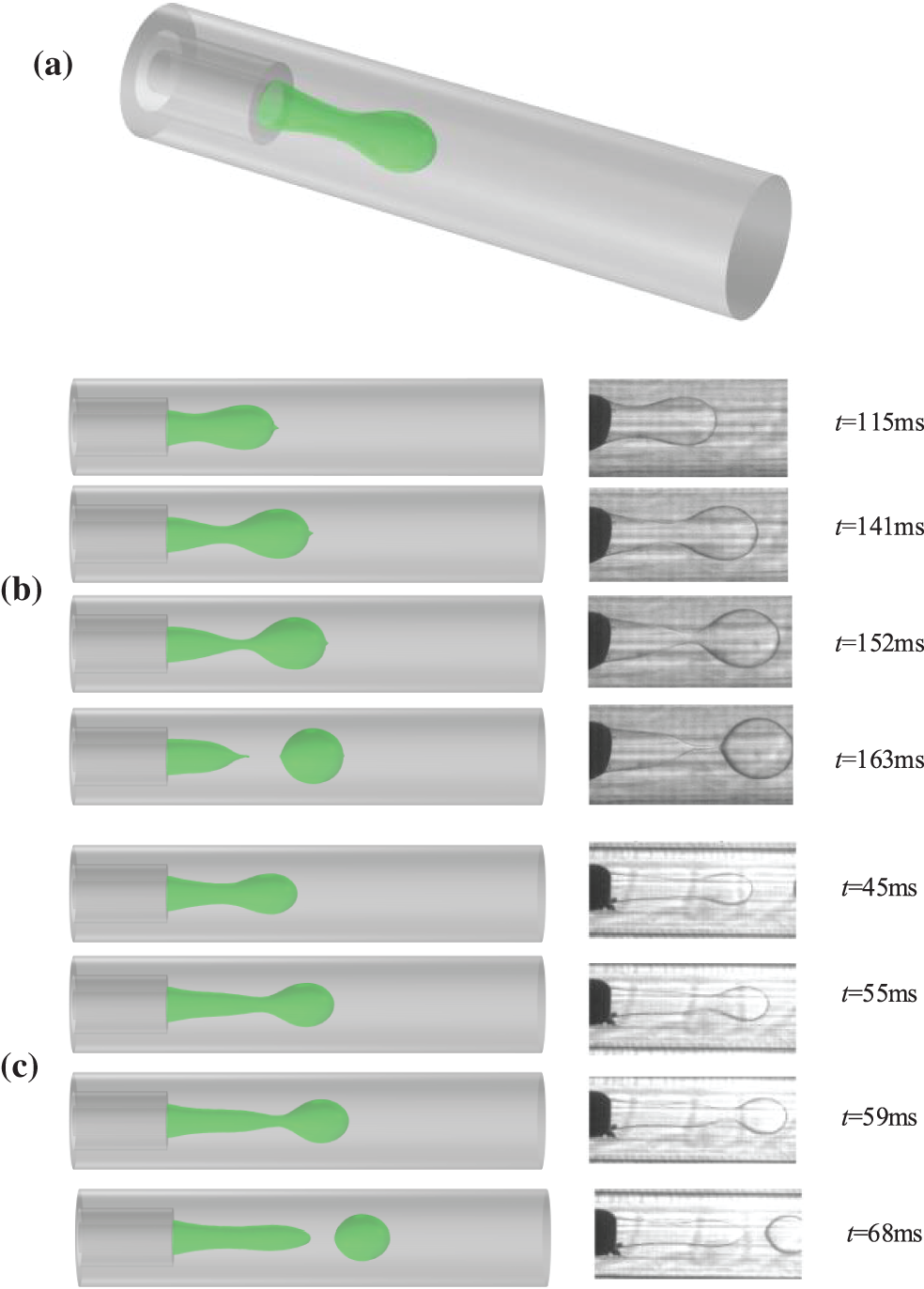
Figure 4: Comparison of droplet generation characteristics (our simulations are on the left, and Lan’s experiments [36] are on the right); (a) three-dimensional model, (b) drop flow at η = 6 and Cac = 0.12, (c) jet flow at η = 7 and Cac = 0.41
3 Flow Evolution of Droplet Generation
The flow pattern of droplet generation is strongly influenced by the flow velocity ratio η and the capillary number Cac. The conversion between flow patterns can be obtained by changing these two parameters (i.e., η and Cac). As shown in Fig. 5, four different flow types, drop flow, jet flow, squeeze flow, and co-flow, can be observed from the coaxial microchannel. If the pinch-off length L is more than triple the diameter d of the generated droplets, this situation is not called jet flow; instead, it is called drop flow. In addition, there is a transitional stage in the transformation between two flow patterns, for example, increasing the Cac number in the state of drop flow results in a transitional flow pattern, which has a shorter jet streamline than jet flow, but a longer flow streamline than drop flow.
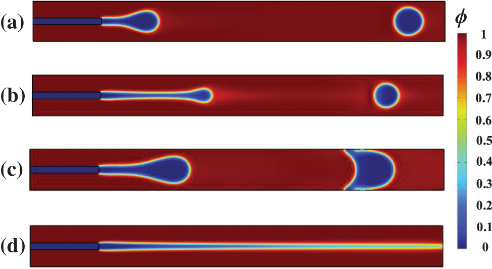
Figure 5: Flow patterns occurring in coaxial microchannels; (a) drop flow, (b) jet flow, (c) squeeze flow, (d) co-flow
3.2 Droplet Pinch-Off Mechanism in Drop Flow and Jet Flow Patterns
In coaxial microchannels, the droplet flow and jet flow are flow patterns that can generate liquid droplets. As shown in Fig. 6a, in a droplet flow pattern, droplets are generated near the tail part of the microchannel. The velocity distribution and pressure distribution showed that the pressure difference between the inside and outside of the generated droplet becomes very prominent, and the pressure at the thinnest part of the liquid bridge is the largest. The dispersed phase continues to move forward within the continuous phase, and the velocity continues to increase until the liquid bridge breaks and forms droplets. This process is known as the end-pinch mechanism. Fig. 6b shows the droplet growth process in the jet flow pattern, and the liquid bridge of jet structure was longer compared to the drop flow pattern. At this point, the liquid bridge is about to break, the pressure on the connecting neck reaches its peak, while the speed also continuously increases. When the end of the jet is pinched off, the surface tension between the two phases is difficult to keep the interface of the two-phase stable, and droplets are generated in the dispersed phase.
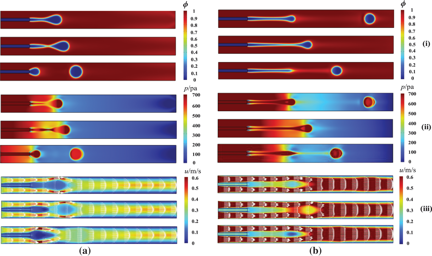
Figure 6: Droplet pinch-off mechanism (i) phase distribution, (ii) pressure distribution and (iii) velocity distribution; (a) drop flow and (b) jet flow
As shown in Fig. 7, the co-flow pattern is a common flow pattern in microchannels, mainly occurring in the case of a dispersed phase with larger capillary numbers. The dispersed phase does not produce continuous droplets in the channel but presents a stable parallel flow. The co-flow pattern is widely found in cases where the capillary number Cac is greater than 1. The squeeze flow pattern mainly occurs in conditions where the capillary number and flow velocity ratio are very small. In the squeeze flow, the dispersed phase blocks the flow progression of the continuous phase, resulting in slugging of the continuous phase. The drop flow does not form a slug structure and is a flow pattern that can stably produce liquid droplets. When Cac = 0.1–0.3, as long as the flow velocity ratio is large enough (η > 1.5), the drop flow pattern can be generated. The jet flow pattern can also generate droplets, and their flow process involves the growth, deformation, and pinching of the jet streamline. When droplets are generated, the jet streamline may have a long streamline length, so the diameter distribution of the generated droplets is not uniform. Our study found that Cac = 0.4 was a critical threshold for the appearance of the jet flow pattern.
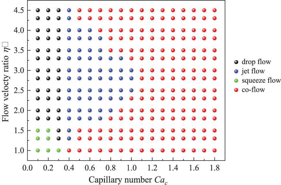
Figure 7: Flow pattern map of oil/water two phase flow in coaxial microchannels
4.1 Effect of Flow Velocity Ratio
The flow velocity ratio at the inlet had a significant influence on the generation characteristics of droplets, and the shape of droplets varied greatly at different velocity ratios. The flow velocities of the continuous phase were designated as uc = 0.1, 0.14, 0.18 and 0.22 m/s, and the oil droplet generation processes were numerically simulated at five different flow velocity ratios of η = 1.8, 2.1, 2.4, 2.7 and 3 to study the effects of different flow velocity ratios on the generation processes of oil droplets.
Fig. 8 shows the effect of flow rate ratio η on the frequency, diameter, and pinch-off length of droplet generation. The flow velocity of the continuous phase flow uc remained unchanged, and the influence of flow velocity ratio on droplet formation characteristics was reflected by adjusting the flow velocity of the dispersed phase ud. The larger the flow velocity ratio was, the higher the droplet generation frequency was. When the flow velocity ratio was at 2.1 and 2.4, there was a small effect of the velocity of the continuous phase on the droplet generation frequency, but a significant effect on the generation diameter and pinch-off length of the droplets. At the same flow velocity ratio, the continuous phase flowed at higher velocities, which resulted in smaller droplet diameters, shorter pinch-off lengths, and higher frequency of droplet generation.
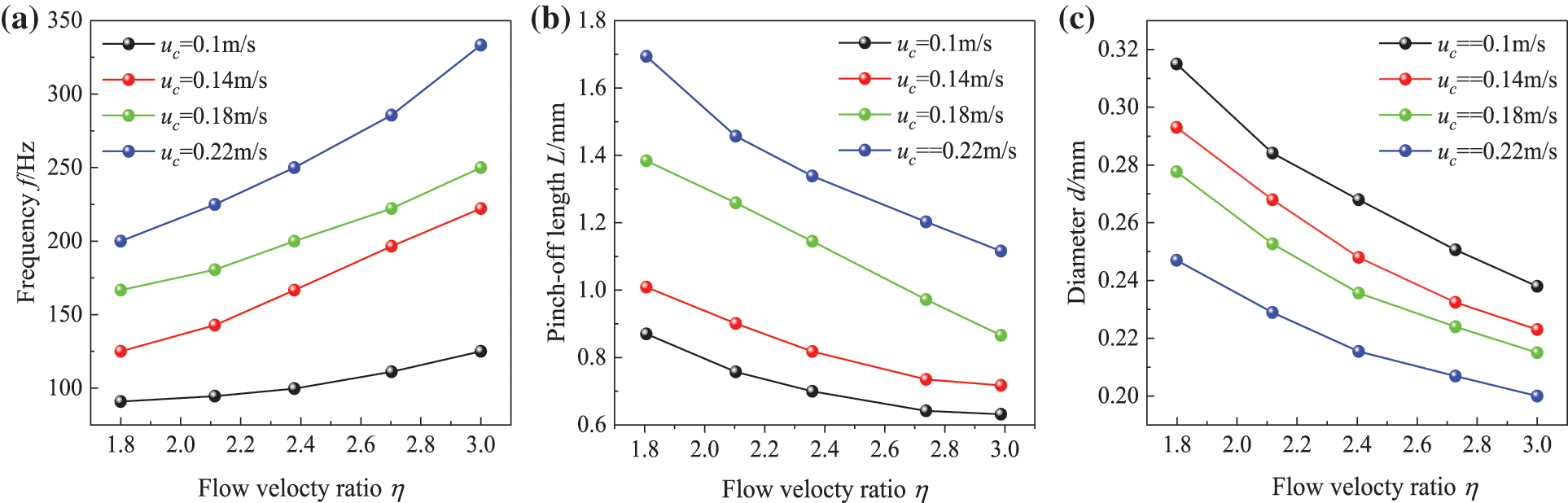
Figure 8: Effects of flow velocity ratio; (a) frequency f, (b) pinch-off length L and (c) diameter d
4.2 Effect of Channel Diameter Ratio
The channel diameter ratio is defined as λ = dc/dd, where dc and dd are the channel widths of the continuous phase and dispersed phase, respectively. The width of the channel determines whether oil droplets can be generated in the microchannel. If the width of channel is too narrow, it can cause droplets to generate squeezed flow inside the channel. Squeezing flow is the flow pattern with the largest droplet size among all flow patterns. In the squeezing flow pattern, the generated droplets block the entire channel, and the flow of the dispersed phase is subject to resistance. Jena et al. [43] studied the effect of channel geometry on the frequency of droplet generation in the T-junction microchannels and reported that the droplet production frequency decreases with an increase in the width of the continuous phase channel. Ji et al. [44] reported the effects of the cross-sectional shape and height-to-width ratio of microfluidic channels on the size and uniformity of generated droplets. Kim et al. [45] examined the effects of the intersection angle between the inlet channels on the droplet diameter and found that the smallest diameter droplet formed when the intersection angle was 90 degrees. Tan et al. [46] studied the effect of inlet width of the bifurcating junction on the breakable droplet sizes. The channel widths of the dispersed phase were set to dd = 0.03, 0.04, 0.05, and 0.06 mm. To investigate the effect of the channel diameter ratio on the microdroplet generation characteristics, the channel widths of the continuous phase were obtained in five multiples of λ = 4, 4.5, 5, 5.5 and 6.
Fig. 9 shows the effect of channel diameter ratio on the frequency, diameter, and pinch-off length of droplet generation. The effect of the channel diameter ratio on the droplet generation characteristics was determined by adjusting the channel width dc of the continuous phase. The larger the channel diameter ratio was, the lower the droplet generation frequency was, and the larger the diameter of droplet generation was, the longer the droplet generation pinch-off length was. At a certain diameter ratio, the droplet generation frequency was lower and the diameter was larger as the channel width of the dispersed phase grew larger, and the pinch-off length of droplet generation was also larger.
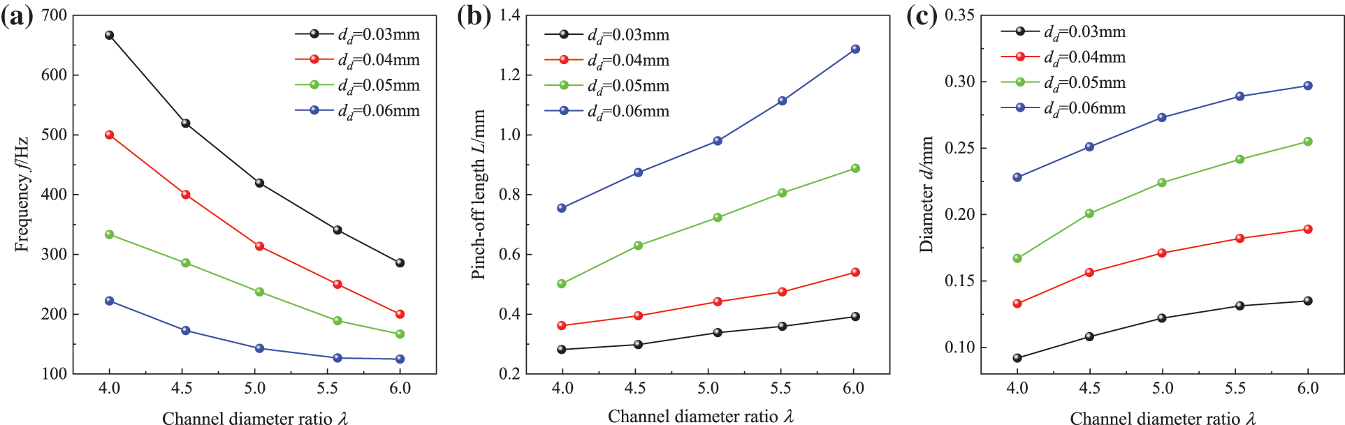
Figure 9: Effects of channel diameter ratio on (a) frequency f, (b) pinch-off length L, and (c) diameter d
The difference in density between the water phase and the oil phase affects the generation of droplets in the channel. The initial densities of the water phase were set as
Fig. 10 shows the effect of density ratio on droplet generation frequency, diameter distribution, and pinch-off length. With the increase of density ratio, the droplet generation frequency remained almost constant, while the diameter of oil droplet generation grew larger and the droplet pinch-off length became shorter. The water phase density of
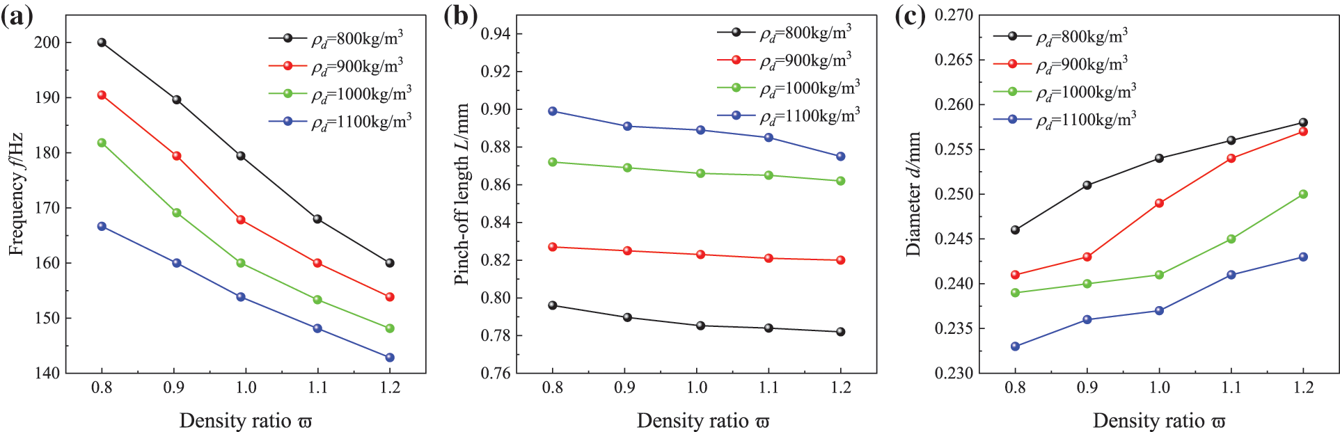
Figure 10: Effects of density ratio on (a) frequency f, (b) pinch-off length L, and (c) diameter d
The effect of viscosity ratio (δ = μd/μc) of the dispersed and continuous phases on oil droplet generation was investigated. The flow velocity ratio, density ratio, and surface tension of the dispersed and continuous phases were kept constant, and the viscosity of the continuous phase was set to μc = 0.0005, 0.001, 0.0015, and 0.002 Pa⋅s, respectively. Numerical simulations were conducted to study the process of oil droplet generation under five different viscosity ratios, δ = 50, 100, 150, 200, and 250, respectively.
Fig. 11 shows the effect of viscosity ratio on the generation frequency, diameter, and pinch-off length of droplets, respectively. The effect of density ratio on droplets was determined by adjusting the viscosity of the oil phase. Changing the viscosity ratio had little effect on the droplet generation frequency. When the viscosity of continuous phase was held constant, the droplet generation frequency increased as the viscosity of the dispersed phase grew larger. In addition, as the viscosity ratio increased the droplet generation diameter became smaller and the pinch-off length grew longer, which was more obvious when the viscosity of the water phase was μc = 0.002 Pa⋅s. It shows that as the viscosity of oil droplets increased, the process of oil droplet formation needed to overcome the effect of larger viscous forces, so the pinch-off length of oil droplet formation grew longer.
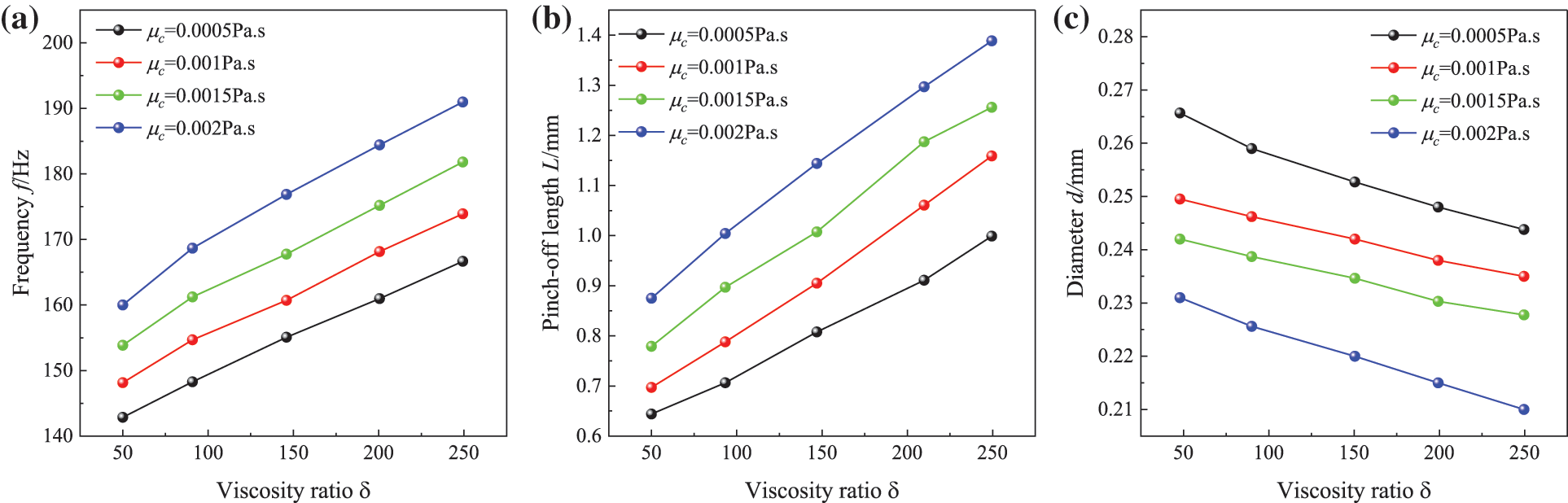
Figure 11: Effects of viscosity ratio on (a) frequency f, (b) pinch-off length L, and (c) diameter d
The formation of a liquid line is mainly caused by the surface tension and pressure difference at the interface of the oil-water phases, and the surface tension plays a significant role in the formation of oil droplets. The oil-water density ratio and viscosity ratio were kept constant, and the surface tension coefficient was changed. To explore the effect of surface tension on the process of oil droplet generation, numerical simulations were conducted for five cases of surface tension coefficient of
Fig. 12 shows the variation of the generation frequency, diameter, and pinch-off length of oil droplets under different surface tensions. With the increase of surface tension, the frequency of droplet generation gradually decreased, the diameter of droplet generation increased, and the pinch-off length of droplets decreased. When the surface tension was larger, the interaction between the continuous and discrete phases was larger and the deformation of oil droplets was smaller. The degree of deformation of oil droplets was determined by the interfacial tension between the two phases. As the interfacial tension increased, the ability of oil droplets to resist deformation grew stronger, and the degree of deformation of oil droplets decreased, which meant that the shape of generated droplets gradually transformed from ellipsoidal to spherical.
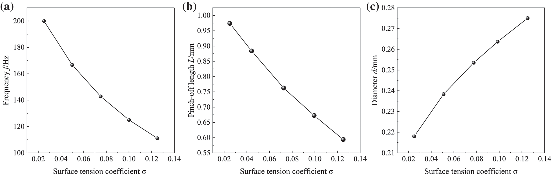
Figure 12: Effects of surface tension on (a) frequency f, (b) pinch-off length L, and (c) diameter d
The oil droplet generation process was numerically simulated by using COMSOL software. The flow pattern of oil droplets in the micro-channel channel was analyzed, and the effects of considering the flow rate ratio, channel diameter ratio, density ratio, viscosity ratio, and surface tension on the oil droplet generation process in the water/oil two-phase flow were analyzed. The main conclusions are as follows:
(1) The frequency of droplet generation tends to increase with the increase of the flow velocity ratio. The larger the flow velocity ratio, the smaller the diameter of droplet generation and the shorter the pinch-off length. The flow velocity ratio in the range of η = 1.8–3 can generate a stable droplet pattern.
(2) Droplet pinch-off length is influenced by the channel diameter ratio and density ratio. With the increase of channel diameter ratio, the long-range resistance of fluid flow becomes smaller, resulting in a longer droplet pinch-off length. As the density ratio increases, the long-range resistance of fluid flow increases, the pinch-off length of droplets becomes shorter.
(3) The change in viscosity ratio exerts an insignificant effect on the frequency of droplet generation. However, as the viscosity ratio increases, the diameter of droplet generation becomes smaller, and the pinch-off length becomes longer.
(4) With the increase of surface tension, the frequency of droplet generation and pinch-off length decrease, but the smaller the increase in the diameter of droplet generation. In addition, a higher surface tension leads to a greater interaction between the two phases, resulting in less oil droplet deformation.
Acknowledgement: All authors are grateful for the hard work of the journal editorial office and the dedication of the Comsol developers.
Funding Statement: This research was funded by University Natural Science Research Project of Anhui Province, Grant Numbers (KJ2020A0826, 2022AH051885, 2022AH051891, 2022AH030160, 62303231), and Intelligent Detection Research Team Funds for the Anhui Institute of Information Technology, Grant Number (AXG2023_kjc_5004).
Author Contributions: The authors confirm contribution to the paper as follows: Data curation, Formal analysis, Writing-original draft: Zongjun Yin. Conceptualization, Project administration, Writing-review & editing: Rong Su. Software, Data curation: Hui Xu. All authors reviewed the results and approved the final version of the manuscript.
Availability of Data and Materials: The data used to support the findings of this study are available from the corresponding author upon request.
Conflicts of Interest: The authors declare that they have no conflicts of interest to report regarding the present study.
References
1. He, C. X., Jiang, B., Zhan, W., Li, S. C., Wang, X. D. et al. (2022). Mesoscale effect on droplet formation in a step-emulsification microdevice with parallel microchannels. Chemical Engineering Journal, 454(2), 140275. [Google Scholar]
2. Liu, L. Y., Wang, H., Zhu, C. Y., Ma, Y. G., Fu, T. T. (2023). Fragmentation of asymmetric liquid filaments and formation of satellite droplets in a microchannel. International Journal of Multiphase Flow, 158, 104290. [Google Scholar]
3. Fan, X. Y., Deng, Z. F., Yan, Y. Y., Orel, V. E., Shypko, A. et al. (2022). Application of microfluidic chips in anticancer drug screening. Bosnian Journal of Basic Medical Sciences, 22(3), 302–314 [Google Scholar] [PubMed]
4. Dong, Y. P., Xiang, X. Y., Wang, Z. D., Zhu, C. Y., Ma, Y. G. et al. (2023). Formation of droplets of shear-thinning non-newtonian fluids in asymmetrical parallelized microchannels. Langmuir, 39(6), 2218–2232 [Google Scholar] [PubMed]
5. Sontti, S. G., Atta, A. (2023). Regulation of droplet size and flow regime by geometrical confinement in a microfluidic flow-focusing device. Physics of Fluids, 35(1), 012010. [Google Scholar]
6. Deng, Y. J., Zhu, C. Y., Fu, T. T., Ma, Y. G. (2023). Coalescence dynamics of nanofluid droplets in T-junction microchannel. Chemical Engineering Science, 265, 118243. [Google Scholar]
7. Hebert, M., Huissoon, J., Ren, C. L. (2022). A perspective of active microfluidic platforms as an enabling tool for applications in other fields. Journal of Micromechanics and Microengineering, 32(4), 043001. [Google Scholar]
8. Geng, Y. H., Ling, S. D., Huang, J. P., Xu, J. H. (2020). Multiphase microfluidics: Fundamentals, fabrication, and functions. Small, 16(6), 1906357. [Google Scholar]
9. Toh, A. G. G., Wang, Z. P., Yang, C., Nguyen, N. T. (2014). Engineering microfluidic concentration gradient generators for biological applications. Microfluidics and Nanofluidics, 16(1–2), 1–18. [Google Scholar]
10. Clime, L., Daoud, J., Brassard, D., Malic, L., Geissler, M. et al. (2019). Active pumping and control of flows in centrifugal microfluidics. Microfluidics and Nanofluidics, 23(3), 2–9. [Google Scholar]
11. Zhang, C., Xing, D., Xu, J. (2007). Continuous-flow PCR microfluidics for rapid DNA amplification using thin film heater with low thermal mass. Analytical Letters, 40(9), 1672–1685. [Google Scholar]
12. Poulos, J. L., Nelson, W. C., Jeon, T. J., Kim, C. J., Schmidt, J. J. (2009). Electrowetting on dielectric-based microfluidics for integrated lipid bilayer formation and measurement. Applied Physics Letters, 95(1), 013706. [Google Scholar]
13. Hess, J. F., Zehnle, S., Juelg, P., Hutzenlaub, T., Zengerle, R. et al. (2019). Review on pneumatic operations in centrifugal microfluidics. Lab on a Chip, 19(22), 3745–3770 [Google Scholar] [PubMed]
14. Zhang, J. F. (2011). Lattice Boltzmann method for microfluidics: Models and applications. Microfluidics and Nanofluidics, 10(1), 1–28. [Google Scholar]
15. Zhang, Y., Nguyen, N. T. (2017). Magnetic digital microfluidics—A review. Lab on a Chip, 17(6), 994–1008 [Google Scholar] [PubMed]
16. Shang, L. R., Cheng, Y., Zhao, Y. J. (2017). Emerging droplet microfluidics. Chemical Reviews, 117(12), 7964–8040 [Google Scholar] [PubMed]
17. Raj, M. K., Chakraborty, S. (2020). PDMS microfluidics: A mini review. Journal of Applied Polymer Science, 137(27), 48958. [Google Scholar]
18. Tang, Q., Zhou, S. R., Hu, R. H., Zheng, H., Pan, J. H. et al. (2020). Generation and transport of dielectric droplets along microchannels by corona discharge. Micromachines, 11(2), 181 [Google Scholar] [PubMed]
19. Majnis, M. F., Francis, H., Shaari, K. Z. K. (2018). Droplet formation in microchannels at low values of the capillary and the reynolds numbers. Materials Today: Proceedings, 5(10), 21765–21771. [Google Scholar]
20. Hirama, H., Wada, S., Shimamura, J., Komazaki, Y., Inoue, T. et al. (2017). Surface modification of a glass microchannel for the formation of multiple emulsion droplets. Microfluidics and Nanofluidics, 21(5), 91. [Google Scholar]
21. Pang, Y., Kim, H., Liu, Z., Stone, H. A. (2014). A soft microchannel decreases polydispersity of droplet generation. Lab on a Chip, 14(20), 4029–4034 [Google Scholar] [PubMed]
22. Yan, Y., Guo, D., Luo, J., Wen, S. Z. (2012). Numerical simulation of droplet dynamic behaviors in a convergent microchannel. BioChip Journal, 7(4), 325–334. [Google Scholar]
23. Zhang, Y., Chen, X., Han, W. (2021). Generation of droplets in double T-shaped microchannels with necked structures. Chemical Engineering & Technology, 44(7), 1241–1250. [Google Scholar]
24. Jing, T., Xubin, Z., Wangfeng, C., Wang, F. M. (2013). Liquid-liquid extraction based on droplet flow in a vertical microchannel. Experimental Thermal and Fluid Science, 49, 185–192. [Google Scholar]
25. Hsiung, S. K., Chen, C. T., Lee, G. B. (2006). Micro-droplet formation utilizing microfluidic flow focusing and controllable moving-wall chopping techniques. Journal of Micromechanics and Microengineering, 16(11), 2403–2410. [Google Scholar]
26. Marculescu, C., Tincu, B., Avram, A., Burinaru, T., Avram, M. (2016). Computational prediction of capillary number impact on droplets formation in microchannels. Energy Procedia, 85(4), 339–349. [Google Scholar]
27. Yan, Y., Guo, D., Wen, S. Z. (2012). Numerical simulation of junction point pressure during droplet formation in a microfluidic T-junction. Chemical Engineering Science, 84(15), 591–601. [Google Scholar]
28. Sivasamy, J., Chim, Y. C., Wong, T. N., Nguyen, N. T., Yobas, L. (2009). Reliable addition of reagents into microfluidic droplets. Microfluidics and Nanofluidics, 8(3), 409–416. [Google Scholar]
29. Li, X. B., Li, F. C., Yang, J. C., Kinoshita, H., Oishi, M. et al. (2012). Study on the mechanism of droplet formation in T-junction microchannel. Chemical Engineering Science, 69(1), 340–351. [Google Scholar]
30. Han, W., Chen, X. (2019). Effect of geometry configuration on the merged droplet formation in a double T-junction. Microgravity Science and Technology, 31(6), 855–864. [Google Scholar]
31. Chen, X., Li, T., Zeng, H., Hu, Z. L., Fu, B. D. (2016). Numerical and experimental investigation on micromixers with serpentine microchannels. International Journal of Heat and Mass Transfer, 98(1), 131–140. [Google Scholar]
32. Yang, L., Li, S., Liu, J., Cheng, J. M. (2018). Fluid mixing in droplet-based microfluidics with T junction and convergent-divergent sinusoidal microchannels. Electrophoresis, 39(3), 512–520 [Google Scholar] [PubMed]
33. Gidde, R. R., Pawar, P. M., Ronge, B. P., Misal, N. D., Kapurkar, R. B. et al. (2017). Evaluation of the mixing performance in a planar passive micromixer with circular and square mixing chambers. Microsystem Technologies, 24(6), 2599–2610. [Google Scholar]
34. Zhu, P., Wang, L. (2017). Passive and active droplet generation with microfluidics: A review. Lab on a Chip, 17(1), 34–75. [Google Scholar]
35. Sethian, J. A., Smereka, P. (2003). Level set methods for fluid interfaces. Annual Review of Fluid Mechanics, 35(35), 341–372. [Google Scholar]
36. Seymen, Z. K., Yucel, H., Karasozen, B. (2014). Distributed optimal control of time-dependent diffusion-convection-reaction equations using space-time discretization. Journal of Computational and Applied Mathematics, 261, 146–157. [Google Scholar]
37. Legay, A., Chessa, J., Belytschko, T. (2006). An Eulerian-Lagrangian method for fluid-structure interaction based on level sets. Computer Methods in Applied Mechanics and Engineering, 195(17–18), 2070–2087. [Google Scholar]
38. Storti, M. A., Garelli, L., Paz, R. R. (2012). A finite element formulation satisfying the discrete geometric conservation law based on averaged Jacobians. International Journal for Numerical Methods in Fluids, 69(12), 1872–1890. [Google Scholar]
39. Shah, I. A., Bilal, S., Asjad, M. I., Tag-ElDin, E. M. (2022). Convective heat and mass transport in casson fluid flow in curved corrugated cavity with inclined magnetic field. Micromachines, 13(10), 1624 [Google Scholar] [PubMed]
40. Lan, W., Li, S., Luo, G. (2015). Numerical and experimental investigation of dripping and jetting flow in a coaxial micro-channel. Chemical Engineering Science, 134, 76–85. [Google Scholar]
41. Wang, F., Nestler, B. (2016). Detachment of nanowires driven by capillarity. Scripta Materialia, 113, 167–170. [Google Scholar]
42. Wang, F., Tschukin, O., Leisner, T., Zhang, H. D., Nestler, B. (2020). Morphological stability of rod-shaped continuous phases. Acta Materialia, 192, 20–29. [Google Scholar]
43. Jena, S. K., Srivastava, T., Bahga, S. S., Bahga, S. S., Kondaraju, S. (2023). Effect of channel width on droplet generation inside T-junction microchannel. Physics of Fluids, 35(2), 022107. [Google Scholar]
44. Ji, H., Lee, J., Park, J., Kim, J., Kim, H. S. et al. (2022). High-aspect-ratio microfluidic channel with parallelogram cross-section for monodisperse droplet generation. Biosensors, 12(2), 118 [Google Scholar] [PubMed]
45. Kim, G. B., Park, Y., Kim, S. J., Park, K. H. (2022). Effect of intersection angle of input channels in droplet generators. Molecules, 27(6), 1791 [Google Scholar] [PubMed]
46. Tan, Y. C., Fisher, J. S., Lee, A. I., Cristini, V., Lee, A. P. (2004). Design of microfluidic channel geometries for the control of droplet volume, chemical concentration, and sorting. Lab on a Chip, 4(4), 292–298 [Google Scholar] [PubMed]
Cite This Article
 Copyright © 2024 The Author(s). Published by Tech Science Press.
This work is licensed under a Creative Commons Attribution 4.0 International License , which permits unrestricted use, distribution, and reproduction in any medium, provided the original work is properly cited.
 Downloads
 Citation Tools