
 Submit a Paper
 Propose a Special lssue
 Open Access
ARTICLE

Analysis and Optimization of the Electrohydraulic Forming Process of Sinusoidal Corrugation Tubes
State Key Laboratory of Advanced Design and Manufacturing Technology for Vehicle, Hunan University, Changsha, 410082, China
* Corresponding Author: Junjia Cui. Email:
Fluid Dynamics & Materials Processing 2024, 20(4), 873-887. https://doi.org/10.32604/fdmp.2023.025833
Received 01 August 2022; Accepted 27 September 2023; Issue published 28 March 2024
 View Full Text
 Download PDF
Abstract
Aluminum alloy thin-walled structures are widely used in the automotive industry due to their advantages related to light weight and crashworthiness. They can be produced at room temperature by the electrohydraulic forming process. In the present study, the influence of the related parameters on the forming quality of a 6063 aluminum alloy sinusoidal corrugation tube has been assessed. In particular, the orthogonal experimental design (OED) and central composite design (CCD) methods have been used. Through the range analysis and variance analysis of the experimental data, the influence degree of wire diameter (WD) and discharge energy (DE) on the forming quality was determined. Multiple regression analysis was performed using the response surface methodology. A prediction model for the attaching-die state coefficient was established accordingly. The following optimal arrangement of parameters was obtained (WD = 0.759 mm, DE = 2.926 kJ). The attaching-die state coefficient reached the peak value of 0.001. Better optimized wire diameter and discharge energy for a better attaching-die state could be screened by CCD compared with OED. The response surface method in CCD was more suitable for the design and optimization of the considered process parameters.Keywords
Thin-walled structures have been widely used in the automotive industry to absorb energy, due to their advantages in crashworthiness and lightweight [1,2]. The strong demand to reduce fuel consumption has led to the adoption of advanced lightweight materials by the automotive industry. Aluminum and aluminum alloys are ideal candidates. The application of aluminum alloys in thin-walled tubes will grow rapidly in the future [3–5].
Geometry and manufacturing defects are two factors that affect the performance of thin-walled tubes during energy absorption. To ensure the absorption performance, a sinusoidal corrugation tube was proposed. This geometry can achieve stabilized collapse mode and low peak crushing force [6]. The traditional manufacturing methods included roll-type incremental forming, welding forming and hydraulic forming, etc. [7,8]. However, among these conventional quasi-static forming processes, the low formability of aluminum and aluminum alloys at room temperature has caused serious problems [9].
The high-speed forming process can improve formability significantly compared with the quasi-static forming process [10]. Three typical high-speed forming processes are the explosive forming process, electromagnetic forming process, and electrohydraulic forming process [5]. During the electrohydraulic forming process (wire-assisted), a pulsed current within a certain parameter range was injected into the metal wire. Joule heat caused a sharp phase transition in the wire. It experienced solid state, liquid state, gas state, and plasma state successively. The plasma channel was generated and expanded outward. Shock waves were generated and propagated by the weak compressibility of the liquid medium [11]. Under the action of the strong shock waves, the metal plate hit the mold at a high speed and plastic deformation occurred.
The electrohydraulic forming process (wire-assisted) could be divided into two steps. The first step was the shock wave generation process. The second step was the high-speed forming process. Peak pressure, specific impulse, and positive pressure action time were used to characterize the shock wave characterization in the first step. However, the mechanism of shock wave generation and energy conversion in the electrohydraulic forming process was complex. There is no complete theory to describe it yet [12]. In recent years, scholars have carried out research on shock wave characteristics by means of experiments. The rules between wire size, discharge parameters, and shock wave parameters under specific conditions were given [13,14]. Some empirical formulas were given [11]. Increasing the energy deposition prior to plasma formation could increase the shock wave intensity. Another way to increase the shock wave intensity was to use a faster pulsed current source to increase the superheat coefficient [15]. Using a large mass of wire to make most of the energy storage for metal phase transitions could also increase the shock wave intensity [16].
Most of the published studies have focused on the improvement of formability and the analysis of the electrohydraulic forming process in the second step. Golovashchenko et al. [17] indicated that the high strain rate and the high hydrostatic stresses were the two factors that improved the formability. The formability improvement mainly occurred in the contact area between the blank and the die. Maris et al. [18] believed that high-speed impact between the sheet and die could improve the formability during the forming of aluminum alloys and steel sheets. Another group of scholars [19,20] used electrohydraulic forming in combination with a quasi-static preforming to improve the formability of the material.
The simulation has been an important tool for analyzing the forming process. Mamutov et al. [21] developed a model based on the application of energy in the plasma channel by channel expansion and pressure pulses through water to the plate. Hajializadeh et al. [22] modeled EHF as an underwater explosion forming. Another group of scholars [23–25] used the pressure waves originating from electrode positions as the loading for the forming process. Hassannejadasl et al. [26] represented the pressure waves by accelerating the hemispherical surface in a liquid medium. The experiment was another reliable tool to analyze the forming process. Other researchers [27] have studied the electrohydraulic forming of sheets through experiments. The key parameters in the forming process were studied. However, the forming of aluminum alloy sinusoidal corrugation tubes at room temperature by means of the electrohydraulic forming process has not yet been studied. The key parameters of the forming process and the evaluation of forming quality need to be studied.
In this study, the electrohydraulic forming process was used to manufacture an aluminum alloy sinusoidal corrugation tube. Firstly, experiments were designed based on the orthogonal experiment design (OED) and central composite design (CCD) technology. Secondly, experiments were carried out. The influence of the wire diameter and the discharge energy on the attaching-die state was analyzed. Subsequently, the optimal arrangement of parameters was given to achieve the best attaching-die state. It was verified by experiments. Finally, the two experimental design methods were compared. The wall thickness distribution was analyzed.
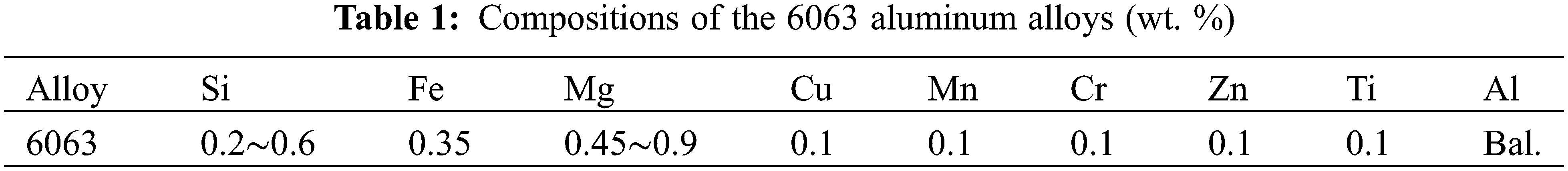
The commercial material 6063 aluminum alloy was used. The thickness of the aluminum alloy tube was 1 mm. The outer diameter of the aluminum alloy tube was 50 mm. The length of the tube was 203.5 mm. The chemical composition is presented in Table 1. The density was 2.7 g/cm3. The tensile strength was 216 MPa, and the Poisson’s ratio was 0.33.
2.2 Electrohydraulic Forming Experiments
The tube was formed by the electrohydraulic forming process. The schematic and equipment of the electrohydraulic forming process are presented in Figs. 1a and 1b. The equipment was divided into two parts: the pulse generator and the forming device. The capacitance of the pulse generator was 408 μF. The maximum energy it could provide was 48 kJ. The forming device included die, upper plate, lower plate and electrodes. The electrodes were made of steel and wrapped with insulating bushings to prevent unnecessary short circuits. The aluminum wire was fixed between the two electrodes. The wire was located in the axial center of the die (facing the third peak). The wire length was 20 mm. Initially, electric energy was stored in the capacitors. When the switch was closed, the high amplitude pulse current passed through the wire. Shock waves were generated. The tube was plastically deformed. Tap water was used in all experiments. For ease of operation and to ensure reasonable utilization of energy, the wire diameters were set to 0.6, 0.8 and 1 mm. The discharge energy of 2.25, 2.5 and 2.75 kJ were selected.

Figure 1: The schematic and equipment of the electrohydraulic forming process: (a) The schematic, (b) the equipment
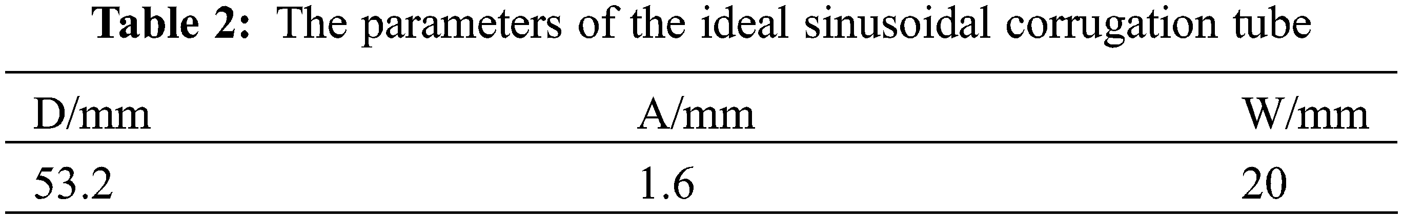
The profile of sinusoidal corrugation and forming process are depicted in Fig. 2. The sinusoidal corrugation tube had 5 peaks. These peaks were labeled 1, 2, 3, 4 and 5 in order of location. The Eq. (1) was used to describe the corrugation profile of the ideal tube walls [6]:
where, D is the mean diameter, A is the amplitude, W is the wave length (the vertical distance). The parameters are shown in Table 2. The wire was located at the center of the peak 3 during the electrohydraulic forming process.

Figure 2: The profile of sinusoidal corrugation and forming process
2.3 Forming Quality Evaluation
After the electrohydraulic forming process, the following function was defined to evaluate the attaching-die state of the tube:
where, C is attaching-die state coefficient, Di is the diameter at each peak after deformation, D0 is the initial outer diameter of the tube, n is the number of peaks. A small value of C indicates good attaching-die state of the tube. All samples were collected in triplicate, the average of the three measurements was presented.
2.4.1 Orthogonal Experiment Design
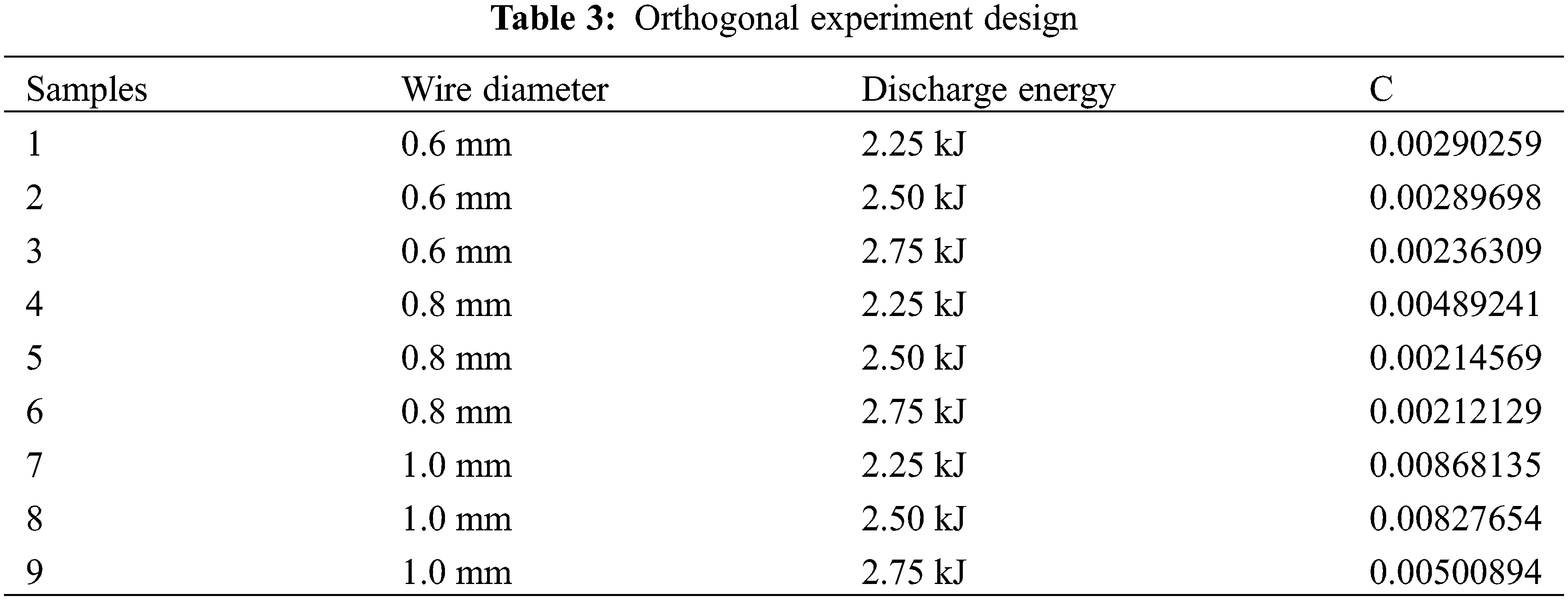
OED is one of the important statistical methods for studying multi-factor and multi-level experiments and analyzing factor design [28,29]. An orthogonal table was used to arrange the experimental and analytical results in the experiment design. An orthogonal table of L9 (32) was selected. In this study, the orthogonal table contained two design variables (discharge energy and wire diameter). The three levels of variables were set as low, intermediate, and high. The OED is listed in Table 3. Table 3 shows that each variable of each level and another variable of each level intersect once, showing orthogonality. Nine sets of combined experiments were conducted.
2.4.2 Central Composite Design
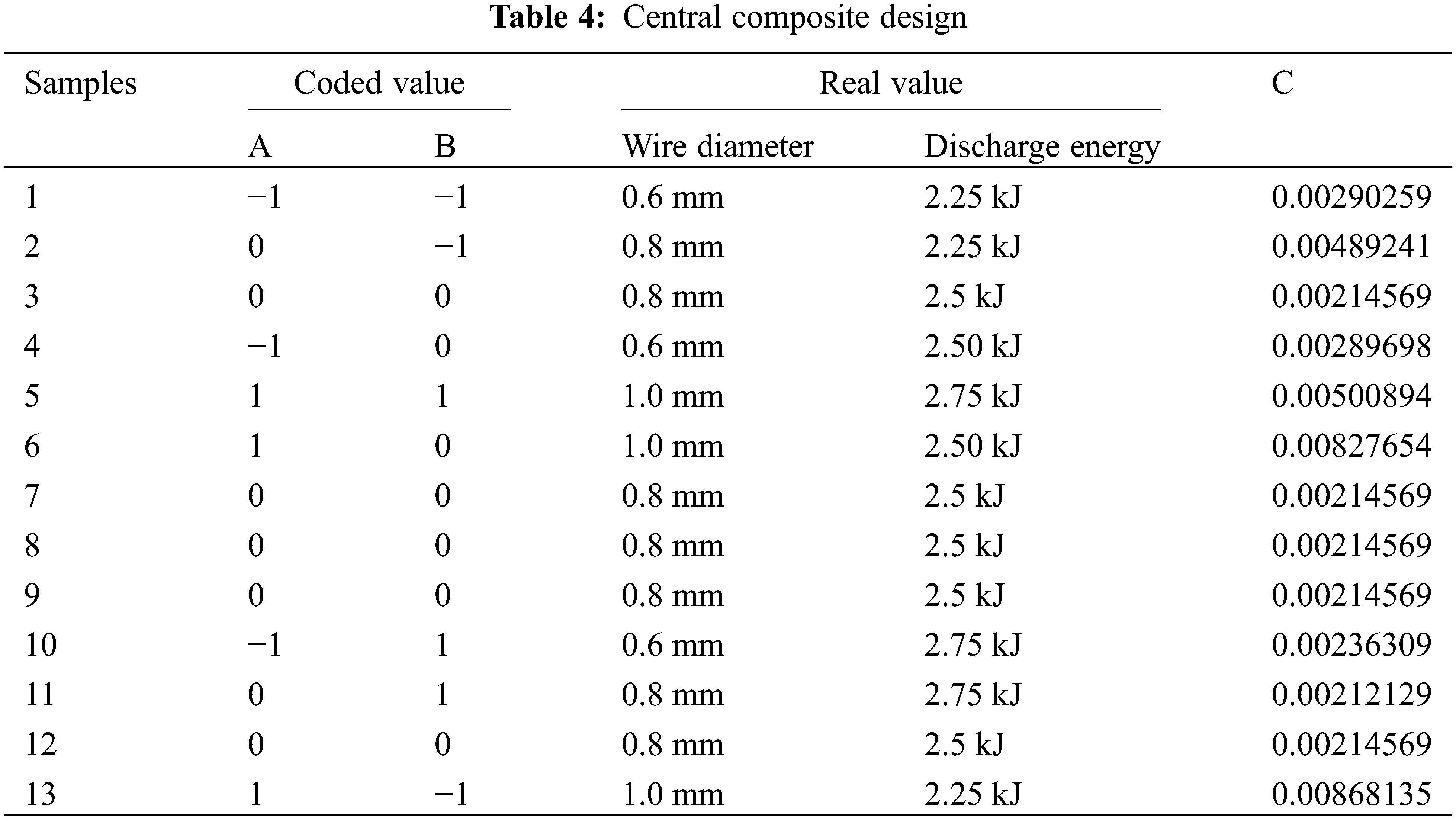
CCD is a method suitable for multivariate analysis. This method could determine linear relationships and interactions between variables. The importance of variables relative to the response can also be determined. Information about variables and experimental errors could also be obtained by this method [30]. Two variables (discharge energy and wire diameter) were investigated in this study. Table 4 shows the groups of CCD. CCD was used to analyze the same tests as in OED to ensure accuracy. All samples were obtained in triplicate.
2.5.1 Direct-Vision Comparison Method
Direct-vision comparison and indirect vision comparison were used to compare the measurement results of the same indicator directly or indirectly. The direct-vision comparison method is a comparison method that does not rely on any functional relationship. It was adopted to compare the attaching-die state coefficient of each sample in the OED.
The response surface method is a statistical method for solving multivariate problems [30]. In this study, the experimental data were obtained by means of the CCD method and experiments. The functional relationships between attaching-die state coefficient and variables (discharge energy and wire diameter) were obtained by the following second-order polynomial regression model:
where, β0 stands for regression intercept, βi, βii, βij are the linear, quadratic, and linear interaction effects of the variables, respectively. xi, xj are variables in the electrohydraulic forming process. The model could be used to optimize the attaching-die state coefficient according to the domains of variables. The optimal set of variables could be obtained. Data analysis was performed using the range analysis and analysis of variance (ANOVA).
3.1 Direct-Vision Method and Range Analysis in OED
The formed sinusoidal corrugation tubes are shown in Fig. 3. The experimental design data and results obtained from the orthogonal experiment are presented in Table 3. The influences of wire diameter and discharge energy on attaching-die state are shown in Fig. 4. When the wire diameter was 0.8 mm and the discharge energy was 2.75 kJ, the attaching-die state coefficient of the tube was the smallest, which was 0.00212129. As shown in Fig. 4, when the wire diameter was the same, as the discharge energy increased, the attaching-die state coefficient decreased. The attaching-die state of the sinusoidal corrugation tube increased.

Figure 3: The formed sinusoidal corrugation tubes

Figure 4: Attaching-die state coefficient in the orthogonal experiment
The comparison of the attaching-die state coefficient of the sinusoidal corrugation tube at three discharge energies is shown in Fig. 5. As the wire diameter changed, there was no obvious law in the change of the attaching-die state coefficient. When the discharge energy was 2.25 kJ, as the wire diameter increased, the attaching-die state coefficient increased. The attaching-die state of the sinusoidal corrugation tube became bad. When the discharge energy was 2.5 and 2.75 kJ, as the wire diameter increased, the attaching-die state coefficient first decreased and then increased. When the wire diameter was 0.8 mm, the attaching-die state coefficient was the smallest. The sinusoidal corrugation tube had the best attaching-die state. This may be due to the different energy required for the plasma channel expansion of different diameter wires.
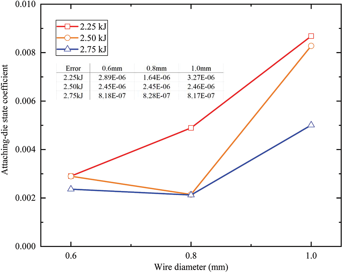
Figure 5: The comparison of the attaching-die state coefficient at three discharge energies in the orthogonal experiment
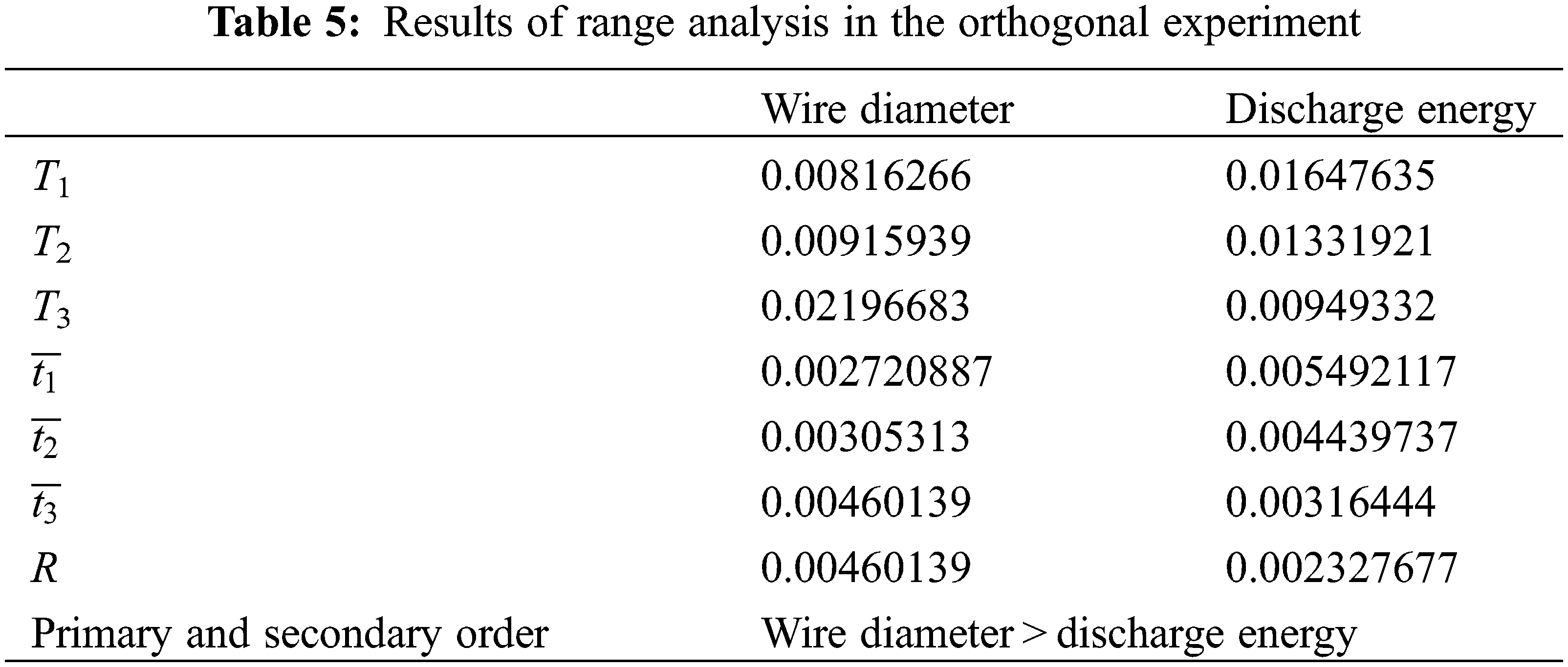
The range analysis was performed on the results of the orthogonal experiment. The effect of process variables on attaching-die state coefficient can be found. T represents the sum of a certain factor and a certain level. The T1, T2 and T3 were calculated using Eqs. (4)–(6):
The range of the attaching-die state coefficient caused by the different levels can be calculated using Eq. (10):
where, R denotes the range of the attaching-die state coefficient. The larger the R value, the greater the influence of the corresponding factors on the attaching-die state coefficient. The result of the range analysis in the orthogonal experiment is shown in Table 5. The results showed that the influence of the wire diameter on the attaching-die state was greater than that of the discharge energy.
ANOVA was performed. The results are listed in Table 6. The coefficient of determination (R2) value was selected to describe the proportion of the variability in the data explained by the ANOVA model and its value of 0.901 suggested acceptable accuracy of the model.
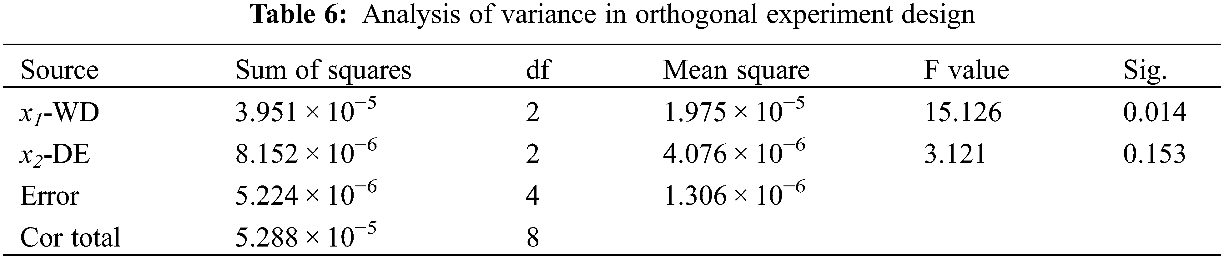
ANOVA results showed that for different wire diameters, the average value of the attaching-die state coefficient was significantly different. For different discharge energies, the average value of the attaching-die state coefficient was not significantly different. The results of ANOVA also showed that the influence of the wire diameter on the attaching-die state was greater than that of discharge energy.
3.2 Response Surface Method in Central Composite Design
The response parameters (attaching-die state coefficient) and the experimental design data obtained using the CCD are shown in Table 4. The attaching-die state coefficient of the response surface is presented in Fig. 6. The quadratic regression equation for the attaching-die state coefficient of the sinusoidal corrugation tube after the electrohydraulic forming process was:
where, x1 and x2 represent wire diameter and discharge energy, respectively. R2 = 0.9404 suggested that the experimental and predicted values were in good agreement based on the response surface method.
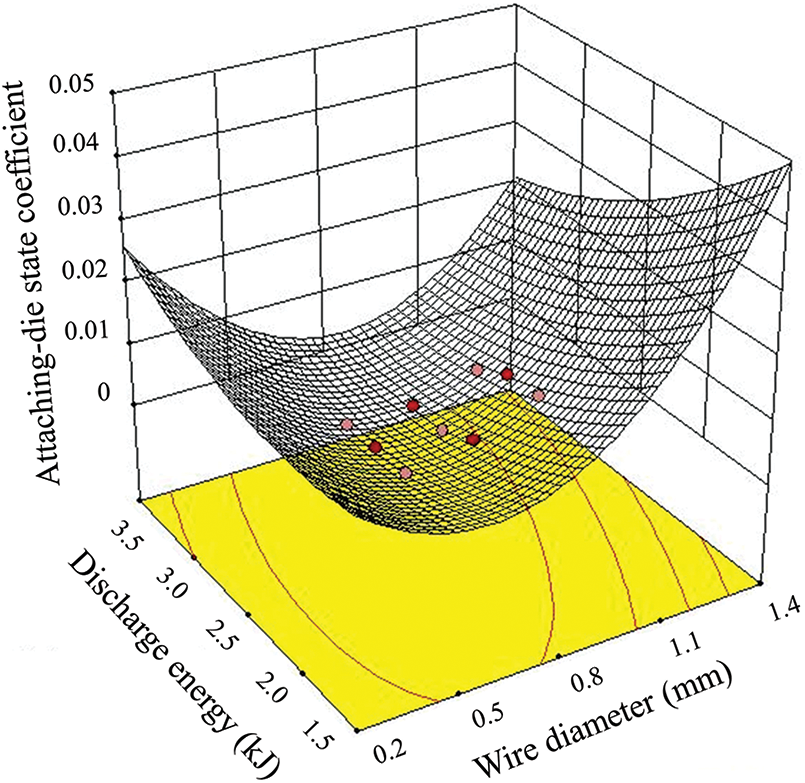
Figure 6: Response surface of the attaching-die state coefficient in central composite design
The results of the ANOVA are given in Table 7. Considering 95% reliability, the model with a probability value (the minimum significance level that may make the null hypothesis H0 negative) below 0.05 was considered significant [27]. According to the ANOVA results and the statistical analysis, the quadratic regression model had an F-value of 22.08, a significantly low probability value of 0.0004 and a lack of fit whose sum of squares was close to 0, indicating that the model was significant. The quadratic regression equation could describe the relationship between variables and response values. The attaching-die state coefficient of the formed sinusoidal corrugation tube can be predicted and analyzed by the quadratic regression equation.
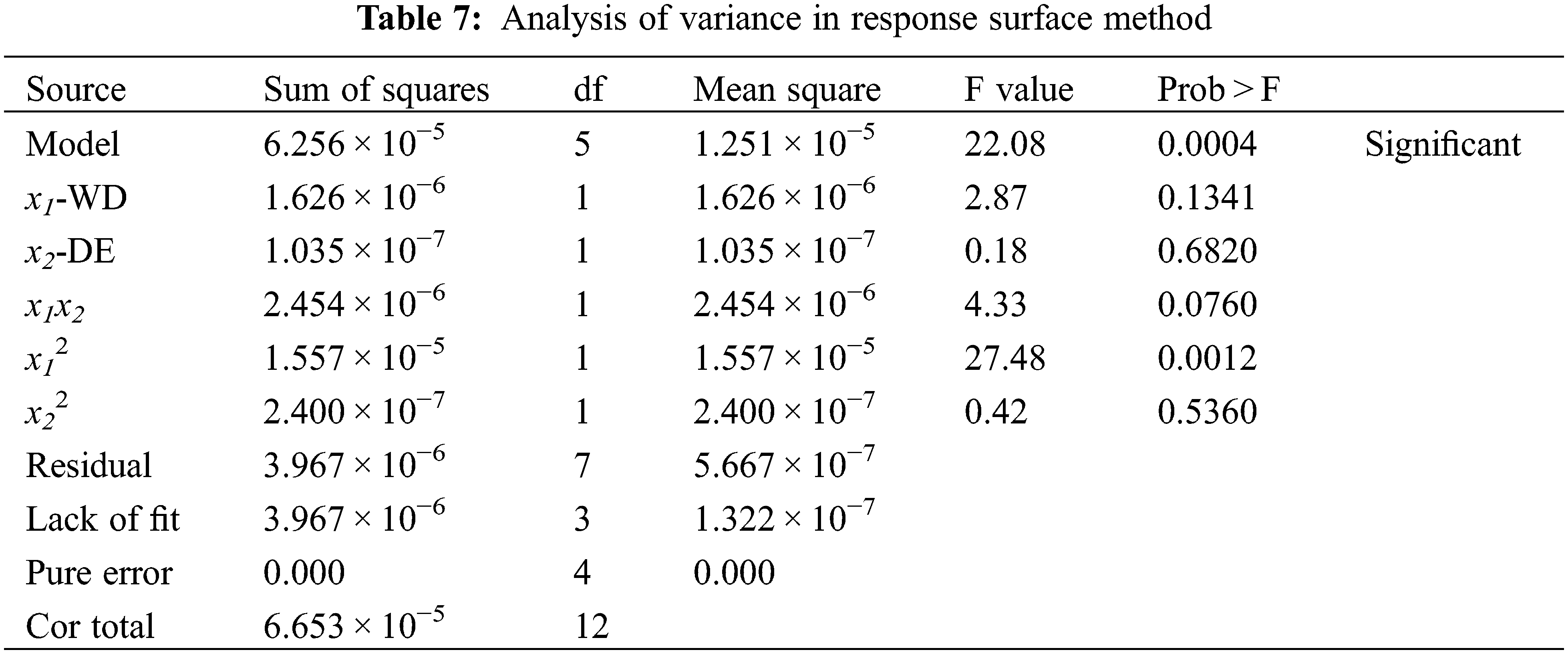
In the ANOVA, the linear terms x1 and x2 had no significant influence on the response. The quadratic term x12 had a significant influence on the response. The quadratic term x22 did not have a significant influence on the response. The interaction term x1x2 did not have a significant influence on the response. The results indicated that the influence of the parameters on the attaching-die state coefficient of the sinusoidal corrugation tube was not a simple linear relationship.
To analyze the influence of various parameters on the attaching-die state of the formed tube, it was necessary to study the main factors in these parameters and their interactions. Fig. 7 represents the contour of the interaction between the wire diameter and the discharge energy. When the wire diameter was 0.8 mm, as the discharge energy increased, the attaching-die state coefficient of the formed sinusoidal corrugation tube firstly decreased and then increased. The attaching-die state was gradually better and then worse. When the discharge energy was 2.5 kJ, as the wire diameter increased, the attaching-die state coefficient of the formed sinusoidal corrugation tube firstly decreased and then increased. The attaching-die state was gradually better and then worse. By analyzing the quadratic regression equation, it was found that when A = 0.759 and B = 2.926, the theoretical minimum value of C was 0.001. This meant that in EHF process when the wire diameter was 0.759 mm and the discharge energy was 2.926 kJ, the attaching-die state coefficient of the sinusoidal corrugation tube was the smallest. The attaching-die state was the best. To verify the model, experiments were performed on the optimal combination of parameters. The experiment result is shown in Fig. 8. When the wire diameter was 0.76 mm and the discharge energy was 2.926 kJ, the attaching-die state coefficient reached 0.0010028 which was quite close to the predicted value of 0.001. Therefore, the model can be used to predict the optimal process parameters.
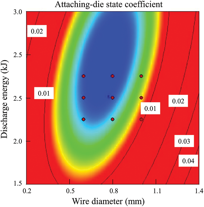
Figure 7: Contour of the interaction between the wire diameter and the discharge energy
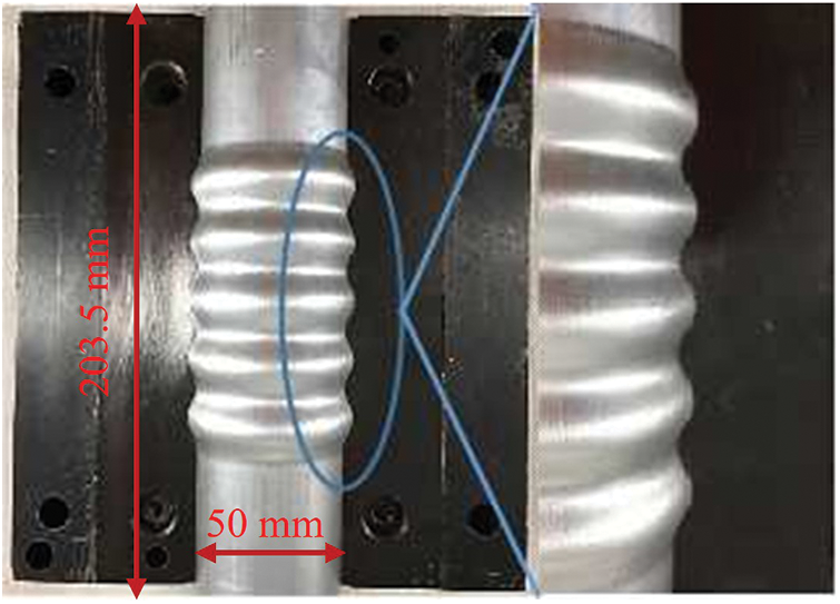
Figure 8: Optimize experiment result
According to the intuitive observation of experimental data, the optimal process parameters in OED are shown in sample 6 in Table 3. The optimum process parameters in CCD were obtained by Eq. (11). It was found that both experiment design methods OED and CCD can be used to optimize process parameters in the electrohydraulic forming process of the sinusoidal corrugation tube. But the results of parameters optimal arrangement were different. The attaching-die state coefficient of the formed tube reached the peak value of 0.00212129, when the wire diameter was 0.8 mm and the discharge energy was 2.75 kJ in OED. When the wire diameter was 0.76 mm and the discharge energy was 2.926 kJ, the minimum attaching-die state coefficient of the formed tube was 0.001. The minimum attaching-die state coefficient of the formed sinusoidal corrugation tube in OED was higher than that in CCD. The best attaching-die state of the formed tube in OED was worse than that in CCD. Therefore, the conclusion was that CCD was more suitable for the electrohydraulic forming process of the sinusoidal corrugation tube.
The reason account for this difference was the different characteristics of the two test design methods. The traditional OED was a design method using a linear mathematical model, which can find the best combination of multiple factors. However, OED can only analyze discrete data, and had the characteristics of low accuracy and poor prediction. The CCD and the response surface method used a non-linear model to obtain high-precision regression equations and made reasonable predictions to find the optimal process conditions.
The attaching-die state coefficient reached a peak of 0.001 when the wire diameter was 0.76 mm and the discharge energy was 2.926 kJ in CCD, but the samples with same parameters arrangement did not appear in OED. Compared to the parameter combination of 0.8 mm and 2.75 kJ, the superheating conditions in the wires were increased due to the larger discharge energy released in the wire of smaller mass. The intensity of the shock wave increased. The attaching-die state coefficient of the sinusoidal corrugation tube was small.
3.4 Wall Thickness Distribution
The thinning rate is one of the important parameters to evaluate the forming quality of bellows. The thinning ratio Rt can be calculated by Eq. (12).
where, t0 is the initial thickness of the tube, tb is the thickness of the bellows. A large thinning ratio indicates severe thinning. The experimental results showed that the maximum thinning ratio was at the center of the sinusoidal corrugation tube (the peak 3 position). Possible reasons are as follows. Firstly, the deformation was the largest at the peaks. Secondly, the center of the tubes was the closest to the explosion position of the wire. The shock load was the largest. Finally, in the high-speed forming process, the material at both ends could not flow to the center in time. The maximum thinning ratio of the sinusoidal corrugation tube under different discharge energies was compared under the condition of wire diameter of 0.8 mm. The result is shown in Fig. 9.
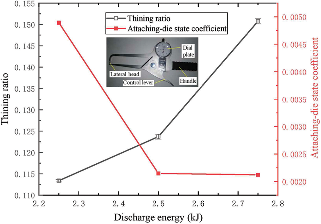
Figure 9: The maximum thinning ratio and the attaching-die state coefficient under different discharge energies (wire diameter was 0.8 mm)
The results showed that the maximum thinning ratio of the sinusoidal corrugation tubes increased with the increase of discharge energy. As shown in Fig. 8, as the discharge energy increased, the attaching-die state coefficient decreased. When the discharge energy was increased from 2.5 to 2.75 kJ, the thinning rate increased by 21.86% and the attaching-die state coefficient decreased by only 1.4%. Possible reasons are as follows. The increase in discharge energy resulted in an increase in shock wave intensity and deformation velocity. The material flow rate was much lower than the deformation rate. However, the amount of deformation due to die limitations was similar. The attaching-die state coefficient did not change much, while the thinning ratio changed significantly.
The electrohydraulic forming process of the 6063 aluminum alloy sinusoidal corrugation tube was studied. The experiments based on OED and CCD were carried out. The influence of process parameters on the attaching-die state was found. The optimal arrangement of parameters was given to achieve the best attaching-die state. The main conclusions could be drawn as follows:
(1) Better optimized wire diameter and discharge energy for a better attaching-die state can be screened by CCD compared with OED. The response surface method in CCD was more suitable for the design and optimization of process parameters in the electrohydraulic forming process of the novel 6063 aluminum alloy sinusoidal corrugation tube.
(2) The influence of the parameters on the attaching-die state coefficient of the sinusoidal corrugation tube was not a simple linear relationship. The results of the nonlinear regression model of the attaching-die state coefficient were in good agreement with the experimental results, indicating that the model can accurately predict the attaching-die state coefficient.
(3) When the wire diameter was 0.76 mm and the discharge energy was 2.926 kJ in CCD, the attaching-die state coefficient reached the peak value of 0.001. The outer surface of the formed tube was in good contact with the inner surface of the die.
Acknowledgement: None.
Funding Statement: This project is supported by National Natural Science Foundation of China (Grant Nos. 51975202 (Junjia Cui received the grant) and 52175315 (Guangyao Li received the grant)).
Author Contributions: The authors confirm contribution to the paper as follows: study conception and design: Da Cai, Hao Jiang, Guangyao Li, Junjia Cui; data collection: Da Cai, Yinlong Song; analysis and interpretation of results: Da Cai, Hao Jiang, Guangyao Li, Junjia Cui; draft manuscript preparation: Da Cai, Hao Jiang, Junjia Cui. All authors reviewed the results and approved the final version of the manuscript.
Availability of Data and Materials: The raw/processed data required to reproduce these findings cannot be shared at this time due to technical or time limitations.
Conflicts of Interest: The authors declare that they have no conflicts of interest to report regarding the present study.
References
1. Tarlochan, F., Samer, F., Hamouda, A. M. S., Ramesh, R., Khalid, K. (2013). Design of thin wall structures for energy absorption applications: Enhancement of crashworthiness due to axial and oblique impact forces. Thin-Walled Structures, 71, 7–17. [Google Scholar]
2. Jiang, H., Liao, Y. X., Gao, S., Li, G. Y., Cui, J. J. (2021). Comparative study on joining quality of electromagnetic driven self-piecing riveting, adhesive and hybrid joints for Al/steel structure. Thin-Walled Structures, 164, 107903. [Google Scholar]
3. Miller, W. S., Zhuang, L., Bottema, J., Wittebrood, A., De Smet, P. et al. (2000). Recent development in aluminium alloys for the automotive industry. Materials Science and Engineering: A, 280(1), 37–49. [Google Scholar]
4. Jiang, H., Zeng, C. C., Li, G. Y., Cui, J. J. (2021). Effect of locking mode on mechanical properties and failure behavior of CFRP/Al electromagnetic riveted joint. Composite Structures, 257, 113162. [Google Scholar]
5. Cai, D., Liang, J., Ou, H., Li, G. Y., Cui, J. J. (2021). Mechanical properties and joining mechanism of electrohydraulic expansion joints for 6063 aluminum alloy/304 stainless steel thin-walled pipes. Thin-Walled Structures, 161, 107427. [Google Scholar]
6. Wu, S. Y., Li, G. Y., Sun, G. Y., Wu, X., Li, Q. (2016). Crashworthiness analysis and optimization of sinusoidal corrugation tube. Thin-Walled Structures, 105, 121–134. [Google Scholar]
7. Lin, J., Wang, X. B., Lei, Y. P., Ding, J. C., Li, K. L. et al. (2021). Residual stress analysis and measurement in multi-layer bellows. Journal of Manufacturing Processes, 72, 179–194. [Google Scholar]
8. Furushima, T., Hung, N. Q., Manabea, K., Sasaki, O. (2013). Development of semi-dieless metal bellows forming process. Journal of Materials Processing Technology, 213(8), 1406–1411. [Google Scholar]
9. Li, G. Y., Deng, H. K., Mao, Y. F., Zhang, X., Cui, J. J. (2018). Study on AA5182 aluminum sheet formability using combined quasi-static-dynamic tensile processes. Journal of Materials Processing Technology, 255, 373–386. [Google Scholar]
10. Psyk, V., Risch, D., Kinsey, B. L., Tekkaya, A. E., Kleiner, M. (2011). Electromagnetic forming-A review. Journal of Materials Processing Technology, 211(5), 787–829. [Google Scholar]
11. Yao, W. B., Zhou, H. B., Han, R. Y., Zhang, Y. M., Zhao, Z. et al. (2019). An empirical approach for parameters estimation of underwater electrical wire explosion. Physics Plasmas, 26(9), 093502. [Google Scholar]
12. Han, R. Y., Zhu, W. Y., Wu, J. W., Li, C., Zhang, C. Y. et al. (2020). Spatial-temporal evolution of plasma radiation in electrical wire explosion: A morphological observation. Journal of Physics D: Applied Physics, 53(34), 345201. [Google Scholar]
13. Han, R. Y., Zhou, H. B., Wu, J. W., Qiu, A. C., Ding, W. D. et al. (2017). Relationship between energy deposition and shock wave phenomenon in an underwater electrical wire explosion. Physics of Plasmas, 24(9), 093506. [Google Scholar]
14. Li, L. X., Qian, D., Zou, X. B., Wang, X. X. (2018). Effect of deposition energy on underwater electrical wire explosion. IEEE Transactions on Plasma Science, 46(10), 3444–3449. [Google Scholar]
15. Grinenko, A., Krasik, Y. E., Efimov, S., Fedotov, A., Gurovich, V. T. et al. (2006). Nanosecond time scale, high power electrical wire explosion in water. Physics of Plasmas, 13(4), 042701. [Google Scholar]
16. Virozub, A., Gurovich, V. T., Yanuka, D., Antonov, O., Krasik, Y. E. (2016). Addressing optimal underwater electrical explosion of a wire. Physics of Plasmas, 23(9), 092708. [Google Scholar]
17. Golovashchenko, S. F., Gillard, A. J., Mamutov, A. V. (2013). Formability of dual phase steels in electrohydraulic forming. Journal of Materials Processing Technology, 213(7), 1191–1212. [Google Scholar]
18. Maris, C., Hassannejadasl, A., Green, D. E., Cheng, J., Golovashchenko, S. F. et al. (2016). Comparison of quasi-static and electrohydraulic free forming limits for DP600 and AA5182 sheets. Journal of Materials Processing Technology, 235, 206–219. [Google Scholar]
19. Gillard, A. J., Golovashchenko, S. F., Mamutov, A. V. (2013). Effect of quasi-static prestrain on the formability of dual phase steels in electrohydraulic forming. Journal of Manufacturing Processes, 15(2), 201–218. [Google Scholar]
20. Golovashchenko, S. F., Bessonov, N. M., Ilinich, A. M. (2011). Two-step method of forming complex shapes from sheet metal. Journal of Materials Processing Technology, 211(5), 875–885. [Google Scholar]
21. Mamutov, A. V., Golovashchenko, S. F., Mamutov, V. S., Bonnen, J. J. F. (2015). Modeling of electrohydraulic forming of sheet metal parts. Journal of Materials Processing Technology, 219, 84–100. [Google Scholar]
22. Hajializadeh, F., Mashhadi, M. M. (2016). Investigation and numerical analysis of impulsive hydroforming of aluminum 6061-T6 tube. Journal of Manufacturing Processes, 20, 257–273. [Google Scholar]
23. Melander, A., Delic, A., Bjorkblad, A., Juntunen, P., Samek, L. et al. (2013). Modelling of electro hydraulic free and die forming of sheet steels. International Journal of Material Forming, 6(2), 223–231. [Google Scholar]
24. Mane, T., Goel, V., Kore, S. D. (2014). Finite element modelling of electro-hydraulic forming of sheets. Procedia Materials Science, 6, 105–114. [Google Scholar]
25. Rohatgi, A., Soulami, A., Stephens, E. V., Davies, R. W., Smith, M. T. (2014). An investigation of enhanced formability in AA5182-O Al during high-rate free-forming at room-temperature: Quantification of deformation history. Journal of Materials Processing Technology, 214, 722–732. [Google Scholar]
26. Hassannejadasl, A., Green, D. E., Golovashchenko, S. F., Samei, J., Maris, C. (2014). Numerical modelling of electrohydraulic free-forming and die-forming of DP590 steel. Journal of Manufacturing Processes, 16(3), 391–404. [Google Scholar]
27. Zohoor, M., Mousavi, S. M. (2018). Evaluation and optimization of effective parameters in electrohydraulic forming process. Journal of the Brazilian Society of Mechanical Sciences and Engineering, 40(11), 524. [Google Scholar]
28. Li, J. Y., Zhu, S. F., Zhu, J. B., Xu, C. Y., Zhang, H. F. et al. (2022). Quality prediction of polygonal helical curved tube by abrasive flow precision machining. International Journal of Advanced Manufacturing Technology, 119(1–2), 827–839. [Google Scholar]
29. Tian, P., Huang, J., Shi, W. D., Zhou, L. (2019). Optimization of a centrifugal pump used as a turbine impeller by means of an orthogonal test approach. Fluid Dynamics & Materials Processing, 15(2), 139–151. https://doi.org/10.32604/fdmp.2019.05216 [Google Scholar] [CrossRef]
30. Ola, O. T., Valdez, R. L., Oluwasegun, K. M., Ojo, O. A., Chan, K. et al. (2019). Process variable optimization in the cold metal transfer weld repair of aerospace ZE41A-T5 alloy using central composite design. International Journal of Advanced Manufacturing Technology, 105(11), 4827–4835. [Google Scholar]
Cite This Article
 Copyright © 2024 The Author(s). Published by Tech Science Press.
This work is licensed under a Creative Commons Attribution 4.0 International License , which permits unrestricted use, distribution, and reproduction in any medium, provided the original work is properly cited.
 Downloads
 Citation Tools