
 Submit a Paper
 Propose a Special lssue
 Open Access
ARTICLE

Linear and Non-Linear Dynamics of Inertial Waves in a Rotating Cylinder with Antiparallel Inclined Ends
1 Laboratory of Vibrational Hydromechanics, Perm State Humanitarian Pedagogical University, Perm, 614000, Russia
2 The Department for Construction Engineering and Material Science, Perm National Research Polytechnic University, Perm, 614990, Russia
* Corresponding Author: Stanislav Subbotin. Email:
(This article belongs to the Special Issue: Advanced Problems in Fluid Mechanics)
Fluid Dynamics & Materials Processing 2024, 20(4), 787-802. https://doi.org/10.32604/fdmp.2024.048165
Received 29 November 2023; Accepted 16 January 2024; Issue published 28 March 2024
 View Full Text
 Download PDF
Abstract
This work is devoted to the experimental study of inertial wave regimes in a non-uniform rotating cylinder with antiparallel inclined ends. In this setting, the cross-section of the cylinder is divided into two regions where the fluid depth increases or decreases with radius. Three different regimes are found: inertial wave attractor, global oscillations (the cavity’s resonant modes) and regime of symmetric reflection of wave beams. In linear wave regimes, a steady single vortex elongated along the rotation axis is generated. The location of the wave’s interaction with the sloping ends determines the vortex position and the vorticity sign. In non-linear regimes several pairs of the triadic resonance subharmonics are detected simultaneously. The instability of triadic resonance is accompanied by the periodic generation of mean vortices drifting in the azimuthal direction. Moreover, the appearance frequency of the vortices is consistent with the low-frequency subharmonic of the triadic resonance. The experimental results shed light on the mechanisms of the inertial wave interaction with zonal flow and may be useful for the development of new methods of mixing.Keywords
A rotating homogeneous fluid can support the internal oscillatory motion known as inertial waves [1]. The existence of these waves is associated with the quasi-elastic properties of the Coriolis force, which tends to return radially displaced liquid particles to their original position. In the absence of viscosity, such a motion would be equivalent to circularly polarized oscillations. If the oscillation frequency is less than twice the rotation rate of the system , the fluid particles describe circles in an inclined direction with respect to the vector
The properties of inertial waves have much in common with internal waves in a stratified fluid, where the difference between gravity and buoyancy forces plays a role of the restoring force. If the density-stratified fluid rotates, inertia-gravity waves arise [9]. In connection with the geophysical applications, the geometry of the spherical shell is of great interest for the research [6]: inertial waves are widespread in the oceans, atmosphere, liquid planetary cores and rotating stars. Nevertheless, the main features of the linear and non-linear wave regimes can be studied in the cavities that are geometrically simpler. On the one hand, the cavity geometry makes it possible to simulate different regimes; on the other hand, the simplicity of setting problems allows discovering new, previously unknown features. For example, in [4,10,11] the cavity was a rotating prism with a rectangular trapezoidal cross-section. We also note a series of works on the study of wave motion in an unevenly rotating cube. If the rotation axis passes through two opposite faces of the cube, then the flow regimes are inertial modes [12,13]. If the rotation axis passes through two opposite vertices, the sources of the waves are the corners and edges of the cube. The appearance of the sloping walls makes it possible to focus the waves into an attractor [14]. In the case of the rotation axis passing through the midpoints of two opposite edges, the spatial structure of the wave patterns becomes more complicated [15].
With an increase in the oscillation amplitude, the non-linear interactions in the wave beam lead to the development of the cascade processes. The perturbations are transmitted to the smaller scales by the mechanism of triadic interactions and dissipate due to viscosity. Most often, the wave attractors of the inertial or internal waves are used for laboratory modelling of the triadic resonance instability [11,16–18]. Nevertheless, the use of the focusing reflection is not necessary to achieve weakly non-linear regimes [19,20]. In a rotating cylinder close to the eigenfrequency of inertial mode, the triadic resonance has been known since McEwan [21] as “resonant collapse”. In a precessing cylinder, the instability satisfies the triadic resonance condition in the form of two inertial modes of the cylinder and one forced Kelvin mode [22,23]. In the case of spherical shell geometry, the triadic interactions appear against the background of the non-axisymmetric instability of the Taylor column [24].
An important issue is the transfer of wave energy to the zonal flow. Thus, the linear and non-linear fluid response in a rotating cavity with one sloping wall is experimentally studied in [4]. The wave focusing on the attractor leads to the generation of a cyclonic mean flow. This flow is localized along the axial cylinder that intersects the sloping bottom at the position where the focusing takes place. It is shown that this is the result of centrifugal instabilities, due to the mixing of angular momentum. A cylindrical cuvette with two parallel inclined ends is used in [25]. Since the attractor branches are reflected from two inclined walls, the number of mean vortices is two. When the focusing reflections are located opposite to each other (near the rotation axis), the vortices are combined into one cyclonic vortex. In the axisymmetric cavity geometry (spherical shell [26] or the annular layer with a sloping bottom [18]), the mean flow has the form of a liquid geostrophic cylinder. In [26], a forcing is introduced into the system by the circular oscillations of the inner core, and in [18]–by precessions of the upper lid representing a flat annular disk. An increase in the oscillation amplitude leads to a non-axisymmetric instability and the appearance of a periodic system (cluster) of the mean columnar vortices. In both cases, the trigger mechanism is the triadic resonance instability. Moreover, the dispersion equation allows one to interpret the vortex cluster as Rossby waves.
Considering the effects mentioned above, inertial waves can be useful for controlling fluid movement in industrial processes. An example is the concept of a soft bioreactor for the culture of microalgae [27]. The resonance of the inertial mode in a precessing cavity creates an effective mixing, resulting in nutrient transfer and more active cell growth. There are laminar planetary mixers, which use the combined effect of the rotation of a cavity around an axis and the rotation around an off-axis distance from the cavity [28]. Mean flows excited by inertial waves can be a convenient tool for controlling heat-mass transfer [29], a chemical reaction at the interface [30], fluidization, and transport of granular medium [31,32].
In this paper, we experimentally study the linear and non-linear fluid response in an unevenly rotating cylinder with two antiparallel inclined ends. Referring to geophysical applications [33], we will use the term “librations” to denote the non-uniform rotation. In contrast to [8], the azimuthal cross-section of the cavity can be conditionally divided into two parts, where the cavity length narrows and expands with radius. It allows us to investigate how the boundary conditions (fluid depth increases or decreases with radius) affect the zonal flow excited by inertial waves. At large amplitudes of librations, the wave regime with the fundamental frequency is destroyed according to the scenario of triadic interactions. For the first time, we study the relationship between subharmonics of the triadic resonance and the appearing mean vortex structures.
2 Experimental Setup and Methodology
The cavity is a circular cylinder of a radius
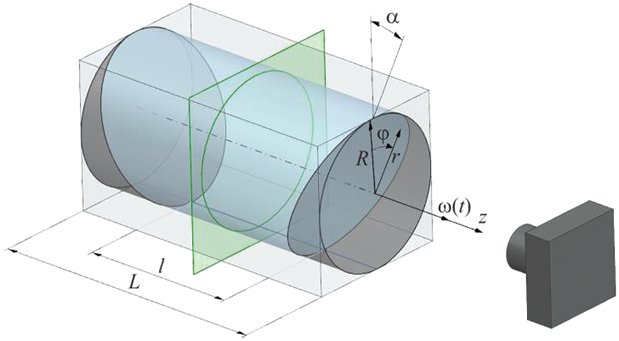
Figure 1: Sketch of a rotating cylinder with the antiparallel ends. The green plane indicates the position of laser sheet
where
The experiments are carried out on the same setup as in [8]. The cuvette is installed in the ball bearings of the vertical metal supports and driven into rotation by a stepper motor (Fulling Motor FL86STH118-6004A). A high-speed camera (CamRecord CL600x2) and a continuous DPSS laser (KLM-532/h-1000) stationary in the laboratory reference frame are used to study the flow structure. The working fluid is a water-glycerol solution with kinematic viscosity
The flow structure is characterized by the Ekman number
3.1 Linear Regimes of Inertial Wave
In a rotating cylinder with sloping ends, librations can excite various resonance wave regimes. The strongest resonant response can be expected when the inertial modes–eigenfrequencies of a rotating fluid in a closed cavity–are excited. These regimes are characterized by large-scale fluid oscillations. On the other hand, due to the wall inclination relative to the rotation axis, inertial wave beams can focus on closed trajectories. To identify the regimes, we plot the time-averaged velocity of the oscillatory flow
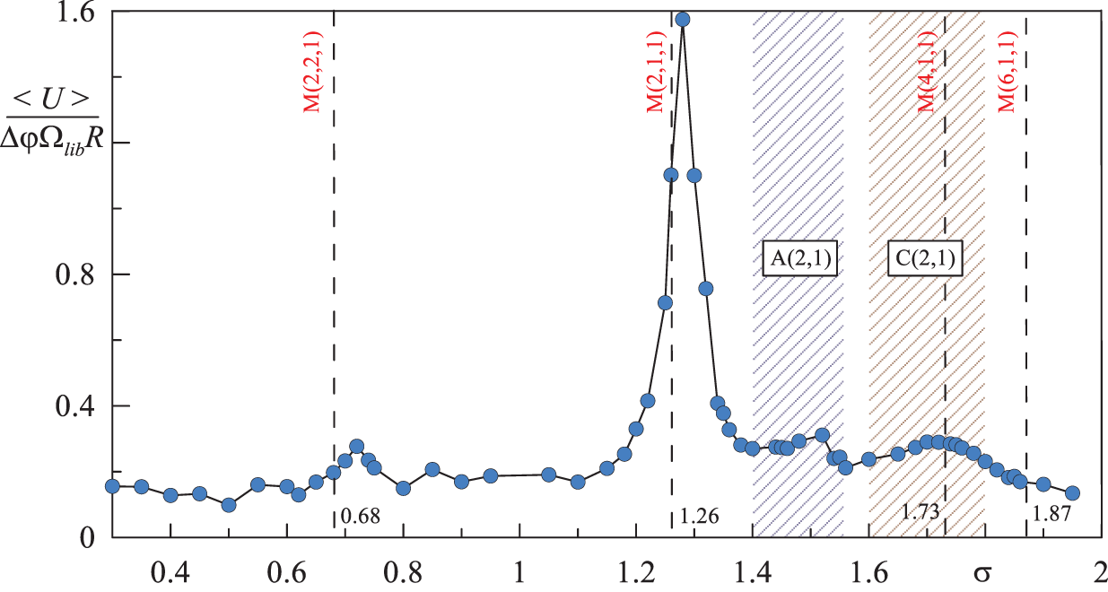
Figure 2: Time-averaged velocity of the oscillatory flow depending on the libration frequency
There is a set of peaks in Fig. 2:
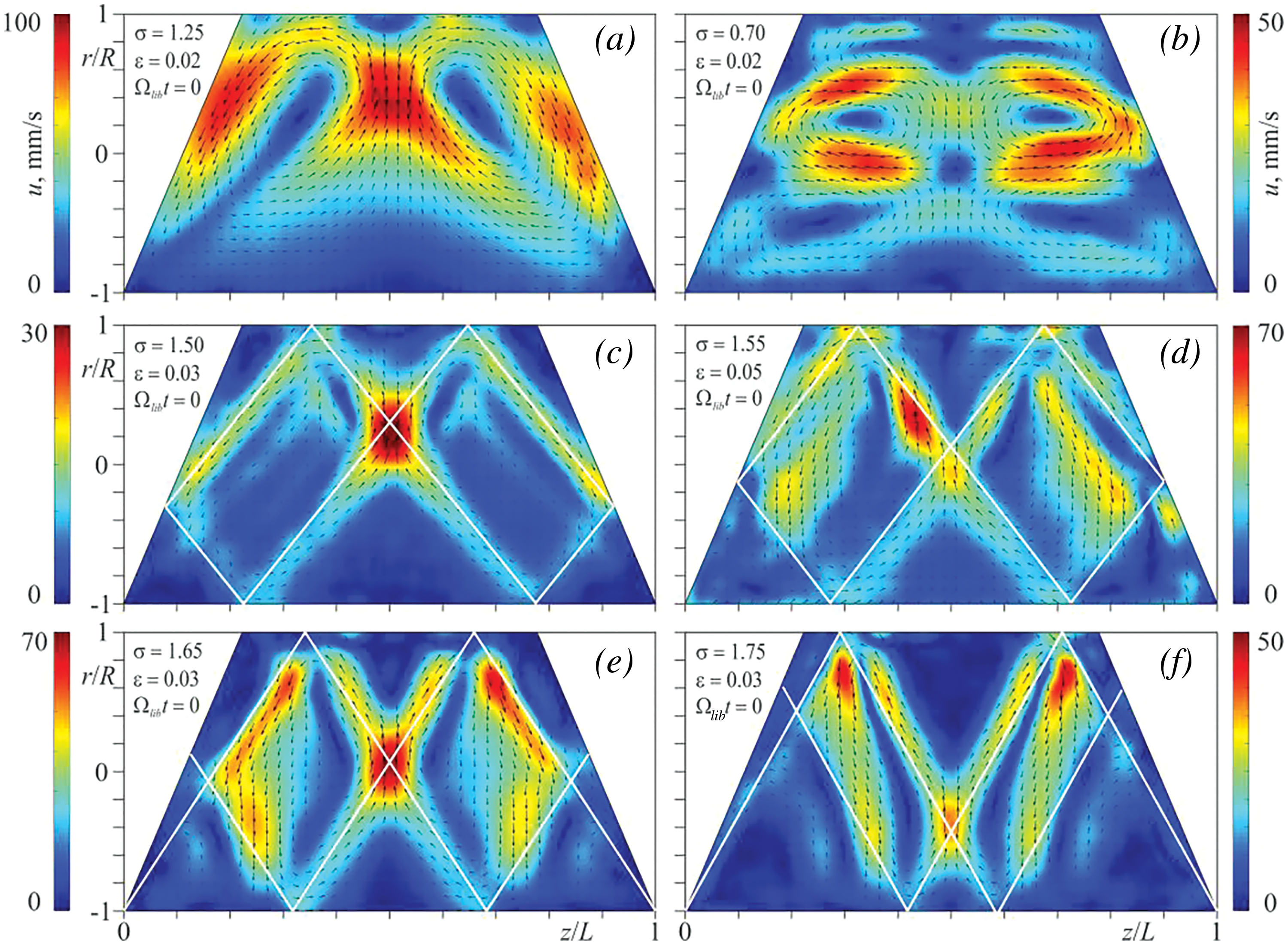
Figure 3: Snapshots of the velocity fields for different regimes in the libration phase
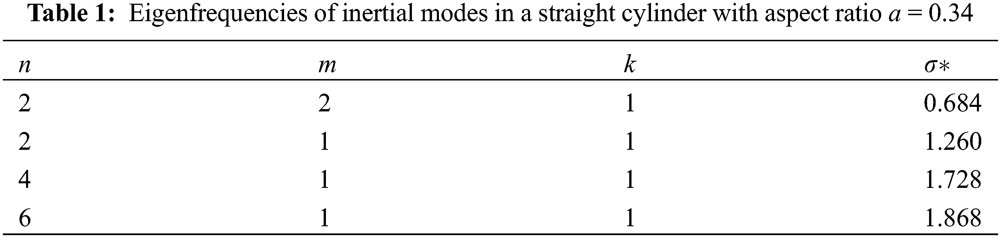
Eigenfrequencies of the inertial modes depend only on the geometry of the cavity, and their values are most easily calculated for a straight cylinder [1]. Therefore to estimate the theoretical values of frequencies
where
Attractors are characterized by the convergence of wave beams to the limit cycle and are denoted as A(n,m), where n and m are the number of reflections from the horizontal and vertical walls in the axial section, respectively. The focusing effects into A(2,1) attractor are observed in the frequency range
In the frequency range
Thus, the cavity geometry supports various wave regimes, which differ in the spatial distribution of wave energy: inertial modes, inertial wave attractor and symmetric reflection of wave beams. The first regime–inertial modes–is characterized by the global fluid oscillations in the cavity. The structure of instantaneous flow is a system of oscillating vortices, the sign of vorticity in which periodically changes (Figs. 3a and 3b). The excitation of the inertial mode M(2,1,1) corresponds to the strongest inertial response of the fluid to the libration forcing (Fig. 2). The next discovered regime is the A(2,1) wave attractor. In this regime, the fluid oscillates along a relatively thin closed trajectory formed by the attractor branches (Figs. 3c and 3d). The focusing of wave beams is ensured by the presence of two inclined boundaries: sequential reflection leads to the narrowing of the wave beam and reaching the limit cycle. The last regime of symmetric wave reflection can be obtained by the first two reflections of beams emitted from the sharp cavity corners (Figs. 3e and 3f). Visually, the C(2,1) regime strongly resembles the A(2,1) attractor and is also accompanied by a local increase in the inertial response (Fig. 2). The main difference is that for the C(2,1) regime, the closed trajectory obtained in the experiments is not a limit cycle. To better understand the behaviour of fluid motion in various regimes, we attach a series of videos (see supplementary materials). The video demonstrates the dynamics of velocity fields in the axial section of the cavity; the colour shows the vorticity.
The fluid oscillations excited by librations lead to the appearance of a steady azimuthal flow. In a straight cylinder in the absence of inertial waves, this flow is retrograde, excluding the region near the side wall where the prograde flow is generated [35–37]. As shown in [38], the generation mechanism is associated with the non-linear effects in Ekman boundary layers on the end walls. The parallel inclination of the ends leads to a violation of the azimuthal flow symmetry along the coordinate
At a frequency
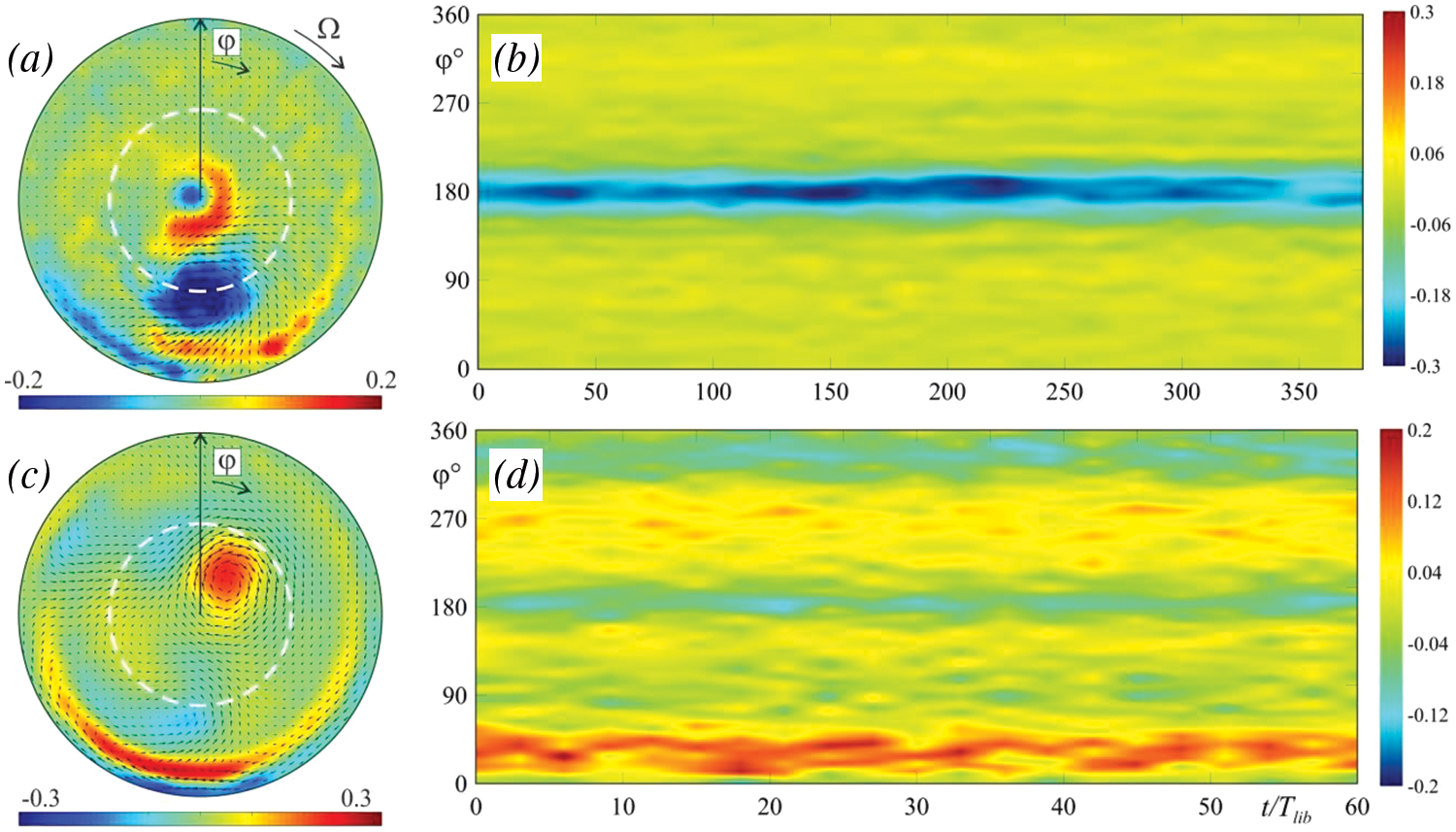
Figure 4: The averaged azimuthal velocity fields in cross-section passing through the cavity center (
Let us discuss the mechanism of the zonal flow generation. The place of the inertial wave interaction with the sloping walls determines the position of the mean vortices. The focusing reflection of the A(2,1) attractor is located at
Previously, the generation of the mean vortices was discovered in a librating cylinder with parallel inclined ends [25]. A cyclonic flow in the form of a cylindrical core arose when the A(1,1) attractor branches were reflected from the rotation axis. The change in the attractor shape and the corresponding displacement of the reflection points from the rotation axis were accompanied by the formation of a system of stationary cyclonic and anticyclonic vortices. Note that in a non-uniform rotating prism with a trapezoidal section, the inertial wave attractor also generates the cyclonic flow [4].
4.1 Zonal Flow Instability and Triadic Resonances
Visual observations from the end wall show that at a critical value of
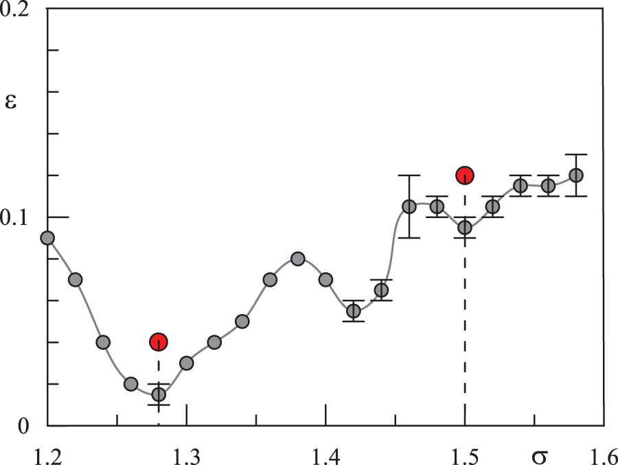
Figure 5: Azimuthal flow instability thresholds depending on the libration frequency (gray dots). The red dots correspond to the experimental results in the non-linear regimes shown in Figs. 6–9
To clarify the instability mechanism of the zonal flow, we study the instantaneous azimuthal velocity field in two cross-sections
where h(t) is the Hamming window.
Fig. 6 shows the spectrograms of the non-linear regimes at frequencies
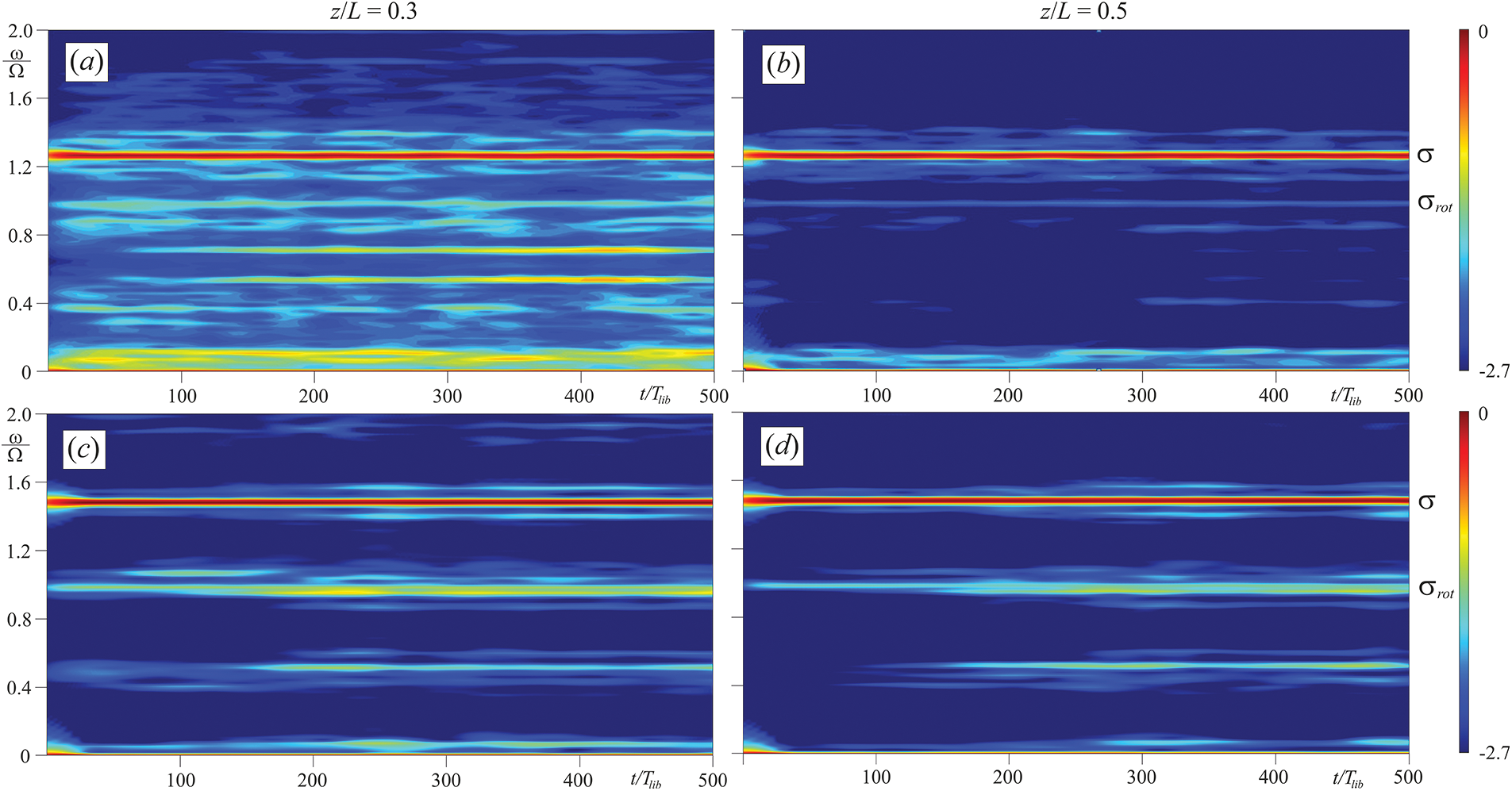
Figure 6: Spectrograms of the azimuthal velocity at
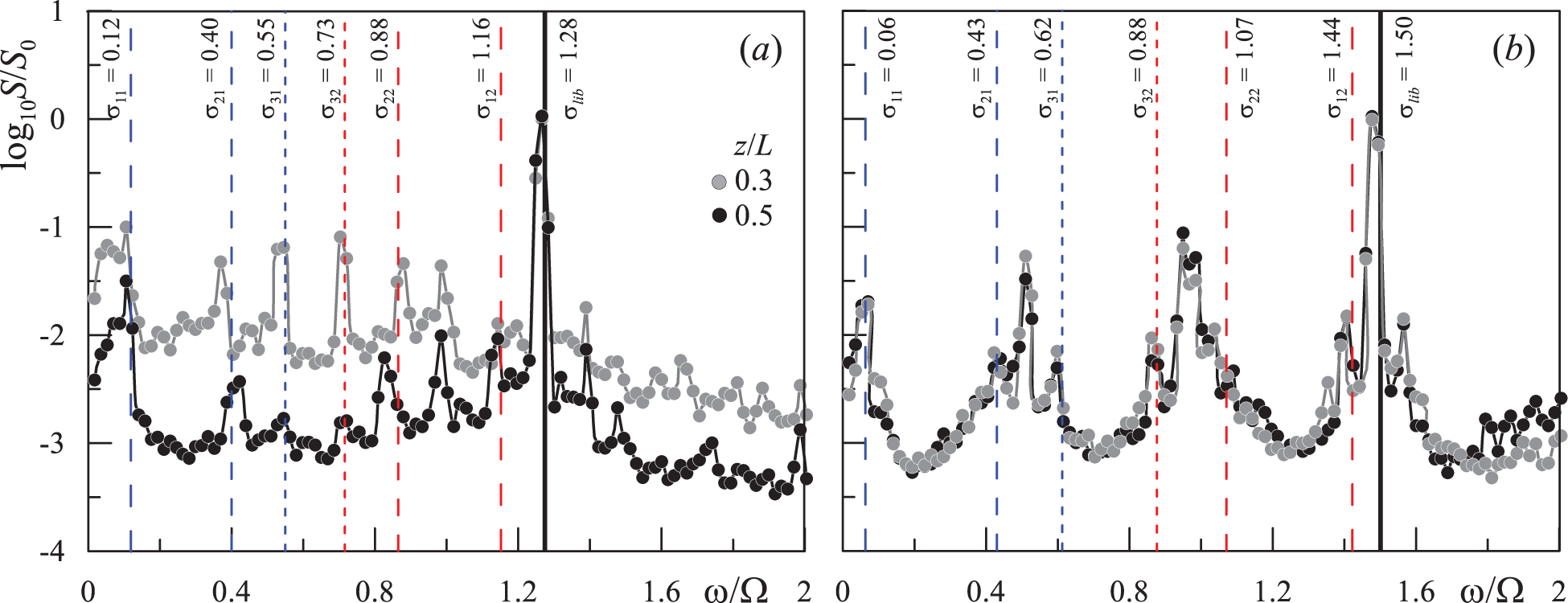
Figure 7: Spectrum of the azimuthal velocity at parameters same as in Fig. 6 and the time moment
In addition to the fundamental frequency, the spectra contain a large number of harmonics, which can be separated into pairs. At
The experiments at frequencies
Thus, the triadic resonance of inertial waves is a trigger for the destruction of the zonal flow and can be a tool for mixing. As noted earlier, in the subcritical region the flow is a single vortex elongated along the rotation axis. This flow resembles a Taylor column, in which the fluid motion along the rotation axis is prohibited [1]. The instability of the triadic resonance should lead to violation of two-dimensionality and the creation of chaotic mixing. It can be noted that mixing under conditions of triadic resonance was studied in [27]. In the non-linear regime, the streaks of the dye have been affected by the flow and spread in the fluid bulk. A detailed study of the characteristics of mixing is beyond the scope of this work.
Let us consider the non-linear fluid response to the triadic resonance instability. Fig. 8 shows the velocity fields averaged over the libration period at different times. At
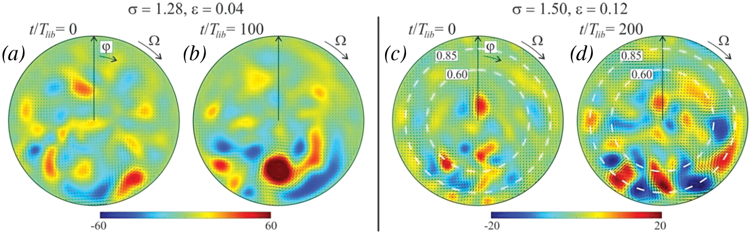
Figure 8: The mean azimuthal velocity fields in non-linear regime at
To further analyze the features of the dynamics of the mean velocity field, let us focus on the frequency
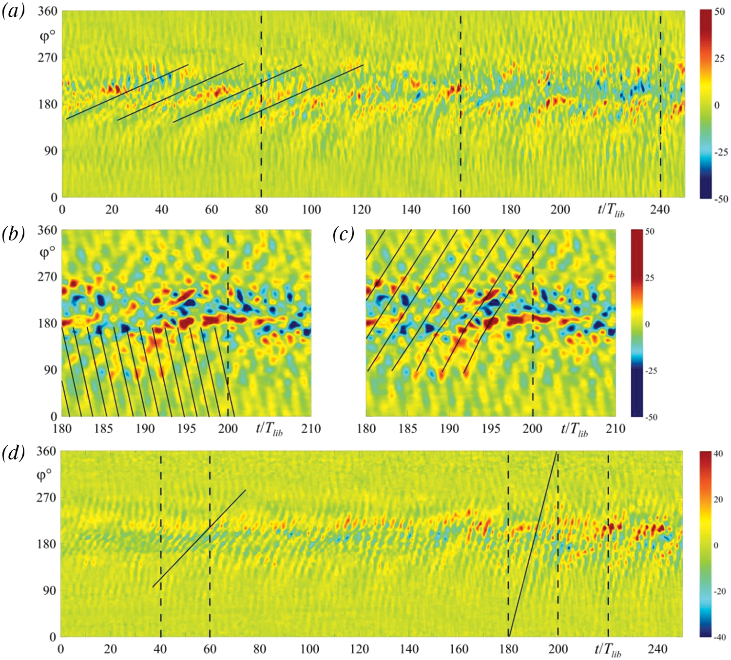
Figure 9: Time-dependence of the average vorticity moving along a ring of radius
The almost vertical lines in Fig. 9a correspond to fairly fast movement against the background of the slow drift. Moreover, at certain moments in time, the vorticity forms the intertwining patterns. For a detailed study of the nature of these structures, let us consider the enlarged fragments of the diagram in a time interval
The most pronounced prograde drift with a frequency
The linear and non-linear fluid response in a non-uniformly rotating (librating) cylindrical cavity with non-axisymmetric ends has been experimentally studied. The case of the antiparallel inclination of the ends relative to the cross-section is considered. The specific shape of the cavity geometry supports several types of inertial regimes: wave attractors, standing waves (so-called inertial modes) and symmetric reflection of the wave beams. The attractor arises due to the successive convergence of the wave beams after reflection from the inclined walls. Thus, the wave energy is localized along one closed trajectory with a sufficiently narrow beam width. The strongest resonant response is observed for the inertial modes, which are the global oscillating vortices. In a trapezoidal axial section, the position of the vorticity centres does not change with time, whereas in a rectangular section, the vortices move in the radial direction. For certain frequencies, the ray-tracing does not predict focusing effects; nevertheless, the wave beams form the closed trajectories. Unlike attractors, the branches of these trajectories at the moment of “focusing” do not lean on the inclined walls of the trapezoidal section and can be geometrically obtained as the first two reflections of the wave beams. It is worth noting that since the libration action is symmetrical, the inertial regimes with even axial wavenumbers arise.
In the linear regimes, inertial waves generate a non-axisymmetric steady azimuthal flow. The flow structure is a single vortex, the position of which is determined by the localization of the wave reflection from the inclined walls. The position of this vortex and the vorticity magnitude do not change with time. Interestingly, the generation of the cyclonic flow occurs in the region close to the acute cavity corners, while the anticyclonic–in the region close to the obtuse corners.
With an increase in the amplitude of librations, the single-vortex flow is destroyed. This process is accompanied by the separation of the main vortex into several pieces, which move in the azimuthal direction. The nature of the system’s non-linear behaviour is related to the triadic resonance instability. Regardless of the flow regime (attractor or inertial modes), several pairs of subharmonics appear in the spectrum, the sum of which is equal to the fundamental frequency. In the non-linear wave regime, the attention is on the long-time dynamics of the mean azimuthal flow. The latter is a system of vortices moving in the azimuthal and radial directions. The vorticity time diagrams show the simultaneous existence of several types of motion with different time scales. We discovered at least three frequencies: slow prograde vortex drift, fast prograde and slow retrograde drift. An estimate of the frequencies of the vortex appearance agrees well with the frequencies of the “lower” subharmonics of triads.
This work continues the study of the influence of the geometry of the end walls on the flow regimes in a rotating cylinder [8,25]. Despite the common features, the experimental setup is a rich dynamical system for studying various wave regimes, while the antiparallel inclination of the ends introduces a peculiar specificity. In contrast to parallel inclination [8,25], wave regimes with even axial wavenumbers are excited. The great interest is the non-linear response of the fluid in the form of generation of the mean single-vortex flow. The discovered dependence of the direction of the steady circulation on the cavity with radius sheds light on the mechanisms of generation of flows in geophysical systems with a
Acknowledgement: None.
Funding Statement: This work was supported by the Ministry of Education of the Russian Federation (Project KPZU-2023-0002).
Author Contributions: Study conception and design: S. Subbotin; data collection: M. Shiryaeva; analysis and interpretation of results: S. Subbotin, M. Shiryaeva, M. Subbotina; writing–original draft preparation: S. Subbotin, M. Shiryaeva, M. Subbotina; writing–review and editing: S. Subbotin. All authors reviewed the results and approved the final version of the manuscript.
Availability of Data and Materials: The data that support the findings of this study are available from the corresponding author.
Conflicts of Interest: The authors declare that they have no conflicts of interest to report regarding the present study.
References
1. Greenspan, H. P. (1968). The theory of rotating fluids. Cambridge: University Press. [Google Scholar]
2. Aldridge, K. D., Toomre, A. (1969). Axisymmetric inertial oscillations of a fluid in a rotating spherical container. Journal of Fluid Mechanics, 37, 307–323. [Google Scholar]
3. Rieutord, M., Georgeot, B., Valdettaro, L. (2000). Wave attractors in rotating fluids: A paradigm for ill-posed Cauchy problems. Physical Review Letters, 85, 4277–4280. [Google Scholar] [PubMed]
4. Maas, L. R. M. (2001). Wave focusing and ensuing mean flow due to symmetry breaking in rotating fluids. Journal of Fluid Mechanics, 437, 13–28. [Google Scholar]
5. Pillet, G., Maas, L. R. M., Dauxois, T. (2019). Internal wave attractors in 3D geometries: A dynamical systems approach. European Journal of Mechanics-B/Fluids, 77, 1–16. [Google Scholar]
6. Rieutord, M., Georgeot, B., Valdettaro, L. (2001). Inertial waves in a rotating spherical shell: Attractors and asymptotic spectrum. Journal of Fluid Mechanics, 435, 103–144. [Google Scholar]
7. He, J., Favier, B., Rieutord, M., Le Dizès, S. (2022). Internal shear layers in librating spherical shells: The case of periodic characteristic paths. Journal of Fluid Mechanics, 939, A3. [Google Scholar]
8. Subbotin, S., Shiryaeva, M. (2023). Inertial wave beam path in a non-uniformly rotating cylinder with sloping ends. Microgravity Science and Technology, 35(3), 32. [Google Scholar]
9. Dintrans, B., Rieutord, M., Valdettaro, L. (1999). Gravito-inertial waves in a rotating stratified sphere or spherical shell. Journal of Fluid Mechanics, 398, 271–297. [Google Scholar]
10. Maas, L. R. M., Benielli, D., Sommeria, J., Lam, F. P. A. (1997). Observation of an internal wave attractor in a confined, stably stratified fluid. Nature, 388, 557–561. [Google Scholar]
11. Brouzet, C., Ermanyuk, E. V., Joubaud, S., Pillet, G., Dauxois, T. (2017). Internal wave attractors: Different scenarios of instability. Journal of Fluid Mechanics, 811, 544–568. [Google Scholar]
12. Boisson, J., Lamriben, C., Maas, L. R. M., Cortet, P., Moisy, F. (2012). Inertial waves and modes excited by the libration of a rotating cube. Physics of Fluids, 24(7), 076602. [Google Scholar]
13. Wu, K., Welfert, B. D., Lopez, J. M. (2018). Librational forcing of a rapidly rotating fluid-filled cube. Journal of Fluid Mechanics, 842, 469–494. [Google Scholar]
14. Wu, K., Welfert, B. D., Lopez, J. M. (2020). Reflections and focusing of inertial waves in a librating cube with the rotation axis oblique to its faces. Journal of Fluid Mechanics, 896, A5. [Google Scholar]
15. Wu, K., Welfert, B. D., Lopez, J. M. (2022). Reflections and focusing of inertial waves in a tilted librating cube. Journal of Fluid Mechanics, 947, A10. [Google Scholar]
16. Scolan, H., Ermanyuk, E., Dauxois, T. (2013). Nonlinear fate of internal waves attractors. Physical Review Letters, 110, 234501. [Google Scholar] [PubMed]
17. Boury, S., Sibgatullin, I., Ermanyuk, E., Shmakova, N., Odier, P. et al. (2021). Vortex cluster arising from an axisymmetric inertial wave attractor. Journal of Fluid Mechanics, 926, A12. [Google Scholar]
18. Subbotin, S., Shmakova, N., Kozlov, V., Ermanyuk, E. (2023). Nonlinear regimes of inertial wave attractors generated by a precessing lid: Zonal flows and Rossby waves. Physics of Fluids, 35(7), 074110. [Google Scholar]
19. Xu, W., Harlander, U. (2020). Inertial mode interactions in a rotating tilted cylindrical annulus with free surface. Physical Review Fluids, 5(9), 094801. [Google Scholar]
20. Monsalve, E., Brunet, M., Gallet, B., Cortet, P. (2020). Quantitative experimental observation of weak inertial-wave turbulence. Physical Review Letters, 125, 254502. [Google Scholar] [PubMed]
21. McEwan, A. (1970). Inertial oscillations in a rotating fluid cylinder. Journal of Fluid Mechanics, 40(3), 603–640. [Google Scholar]
22. Lagrange, R., Eloy, C., Nadal, F., Meunier, P. (2008). Instability of a fluid inside a precessing cylinder. Physics of Fluids, 20(8), 081701. [Google Scholar]
23. Lagrange, R., Meunier, P., Nadal, F., Eloy, C. (2011). Precessional instability of a fluid cylinder. Journal of Fluid Mechanics, 666, 104. [Google Scholar]
24. Barik, A., Triana, S. A., Hoff, M., Wicht, J. (2018). Triadic resonances in the wide-gap spherical Couette system. Journal of Fluid Mechanics, 843, 211–243. [Google Scholar]
25. Subbotin, Shiryaeva, M. (2022). Steady vortex flow induced by inertial wave attractor in a librating cylinder with sloping ends. Microgravity Science and Technology, 34(5), 89. [Google Scholar]
26. Subbotin, S., Shmakova, N., Ermanyuk, E., Kozlov, V. (2022). Stewartson layer instability and triadic resonances in rotating sphere with oscillating inner core. Physics of Fluids, 34(6), 064103. [Google Scholar]
27. Meunier, P. (2020). Geoinspired soft mixers. Journal of Fluid Mechanics, 903, A15. [Google Scholar]
28. Yamagata, T., Sugisawa, H., Fujisawa, N. (2021). Experimental study on laminar mixing in planetary mixer. Experiments in Fluids, 62, 28. [Google Scholar]
29. Kozlov, V. G., Ivanova, A. A., Vjatkin, A. A., Sabirov, R. R. (2015). Vibrational convection of heat-generating fluid in a rotating horizontal cylinder. The role of relative cavity length. Acta Astronautica, 112, 48–55. [Google Scholar]
30. Ivanova, A. A., Kozlov, V. G., Polezhaev, D. A., Pareau, D., Stambouli, M. (2008). The concept of a vibrational cell for studying the interface chemical kinetics. Vibrational flow structure. Fluid Dynamics & Materials Processing, 4(3), 211–220. [Google Scholar]
31. Kozlov, V., Polezhaev, D. (2015). Flow patterns in a rotating horizontal cylinder partially filled with liquid. Physical Review E, 92(1), 013016. [Google Scholar]
32. Watson, P., Bonnieu, S. V., Lappa, M. (2024). Fluidization and transport of vibrated granular matter: A review of landmark and recent contributions. Fluid Dynamics & Materials Processing, 20(1), 1–29. https://doi.org/10.32604/fdmp.2023.029280 [Google Scholar] [CrossRef]
33. Le Bars, M., Cébron, D., Le Gal, P. (2015). Flows driven by libration, precession, and tides. Annual Review of Fluid Mechanics, 47, 163–193. [Google Scholar]
34. Thielicke, W., Stamhuis, E. J. (2014). PIVLab–Time-resolved digital particle image velocimetry tool for MATLAB (version: 1.41). Journal of Open Research Software, 2(1), e30. [Google Scholar]
35. Sauret, A., Cébron, D., Le Bars, M., Le Dizès, S. (2012). Fluid flows in a librating cylinder. Physics of Fluids, 24(2), 026603. [Google Scholar]
36. Subbotin, S. (2022). Steady circulation induced by inertial modes in a librating cylinder. Physical Review Fluids, 5(1), 014804. [Google Scholar]
37. Noir, J., Calkins, M. A., Lasbleis, M., Cantwell, J., Aurnou, J. M. (2010). Experimental study of libration-driven zonal flows in a straight cylinder. Physics of the Earth and Planetary Interiors, 182(1–2), 98–106. [Google Scholar]
38. Busse, F. H. (2011). Zonal flow induced by longitudinal librations of a rotating cylindrical cavity. Physica D, 240(2), 208–211. [Google Scholar]
39. Flandrin, P. (1999). Time-frequency/time-scale analysis, time-frequency toolbox for MATLab. San Diego (CAAcademic Press. [Google Scholar]
40. Sibgatullin, I. N., Ermanyuk, E. V. (2019). Internal and inertial wave attractors: A review. Journal of Applied Mechanics and Technical Physics, 60(2), 284–302. [Google Scholar]
41. Brunet, M., Dauxois, T., Cortet, P. P. (2019). Linear and nonlinear regimes of an inertial wave attractor. Physical Review Fluids, 4(3), 034801. [Google Scholar]
42. Mercier, M., Garnier, N., Dauxois, T. (2008). Reflection and diffraction of internal waves analyzed with the Hilbert transform. Physics of Fluids, 20(8), 086601. [Google Scholar]
Cite This Article
 Copyright © 2024 The Author(s). Published by Tech Science Press.
This work is licensed under a Creative Commons Attribution 4.0 International License , which permits unrestricted use, distribution, and reproduction in any medium, provided the original work is properly cited.
 Downloads
 Citation Tools