
 Submit a Paper
 Propose a Special lssue
 Open Access
ARTICLE

Analysis of the Stability of Filter Materials for Dust Removal and Denitration Integrated Applications
1 State Key Laboratory of Safety and Health for Metal Mines, Ma’anshan, 243000, China
2 Engineering Research Center of Biofilm Water Purification and Utilization Technology, Anhui University of Technology, Ma’anshan, 243032, China
3 Key Laboratory of Metallurgical Emission Reduction & Resources Recycling (Anhui University of Technology), Ministry of Education, Ma’anshan, 243032, China
4 School of Civil Engineering and Architecture, Anhui University of Technology, Ma’anshan, 243032, China
5 School of Energy and Environment, Anhui University of Technology, Ma’anshan, 243032, China
* Corresponding Authors: Fuping Qian. Email: ; Gang Li. Email:
Fluid Dynamics & Materials Processing 2025, 21(4), 833-849. https://doi.org/10.32604/fdmp.2024.056060
Received 13 July 2024; Accepted 25 November 2024; Issue published 06 May 2025
 View Full Text
 Download PDF
Abstract
Nitrogen oxides (NOx) and particulate matter (PM) present significant risks to both human health and environmental sustainability. The Integrated Dust Removal and Denitrification Technology (DRDt) offers a more efficient and cost-effective solution for achieving ultralow industrial flue gas emissions; however, its effectiveness is undermined by low catalyst load rates and poor stability in filter materials. This study addresses these limitations by modifying conventional PTFE filter media (PTFE-Tim) through the incorporation of sodium alginate (SA) and dopamine (DA) as modifiers, resulting in two new filter materials: PTFE–SA–MOF and PTFE–DA–MOF. By optimizing the parameters of an orthogonal experimental design, we identified the ideal preparation conditions for these composite materials. The addition of SA and DA enhanced the bonding between the catalyst (Mn–Cu–MOF) crystal particles and the PTFE fibers through mechanisms such as ion exchange, hydrogen bonding, and adhesion. Consequently, the catalyst loading rate and stability of the DRDt filters were significantly improved. Specifically, the PTFE–SA–MOF and PTFE–DA–MOF filters achieved high catalyst loading rates of 15.97% and 15.86%, these values represent improvements of 2.53 and 2.51 times, while maintaining excellent stability, with mass retention rates of 98.64% and 98.27%, respectively, over the conventional PTFE-Tim filter.Keywords
The issue of air pollution, exacerbated by the rapid rise of global industrialization, has become increasingly critical. Specifically, the emission of pollutants such as particulate matter (PM) and nitrogen oxides (NOx) has caused significant harm to human physical and mental health, triggering photochemical reactions and disrupting the balance of ecosystems [1–3]. The traditional process for industrial flue gas purification is lengthy and requires substantial space. The integration of a powder denitration catalyst with a dust collector enables the combined treatment of dust removal and denitration, representing an enhancement of the conventional dust removal and denitration process. This approach aligns with global energy conservation and emission reduction goals and has emerged as a vital technical solution for controlling industrial flue gas pollutant emissions [4–6].
The integration of dust removal and denitrification technology (DRDt) can be achieved through the in situ loading of the denitration catalyst onto the polymer filter material. MnOx/TiO2/SiC composite filters for the simultaneous removal of NOx and PM can be prepared by loading porous TiO2 aerogels onto SiC ceramic filters [7–9]. The Remedia filter bag combines a V2O5–TiO2 catalyst with polytetrafluoroethylene (PTFE) fiber through a special process, achieving integrated control of DRDt. Metal oxides supported on the surface of PTFE/polyphenylene sulfide membrane composite filter materials facilitate the integrated purification of dust removal and denitrification [10–13]. Computational fluid dynamics (CFD) numerical simulation of dust removal, denitrification, and catalyst stability can be conducted in the NH3–SCR purification process [14–16]. However, most research on integrated filter media primarily focuses on improving the catalytic activity, which is crucial for the practical application value and reliability of the media [17,18]. Bond strength and wear resistance stability are often overlooked. The development of integrated DRDt filter media is primarily hindered by low efficiency and poor stability. Research on the combination of catalysts and polymer-based filter media tends to concentrate on a single parameter, lacking a systematic approach. In the experimental procedure, it is challenging to control the forming process effectively because of the influence of individual parameters on the overall forming quality of composite materials [19,20]. Therefore, it is necessary to optimize the preparation process of integrated filter materials to enhance the competitive advantage of the products.
The orthogonal experiment is an effective method for addressing the challenges of two-factor or multifactor experiments [21–23]. This method allows for a reasonable arrangement of experiments and reduces the overall number of trials. By analyzing various experiments, we can obtain comprehensive results and enhance work efficiency [24,25]. The orthogonal experimental approach can be used to optimize and investigate the stability and performance of polymer-based integrated purification and filtration media for contaminants. Herein, PTFE was utilized as the matrix material to prepare the integrated filter medium for dust removal and denitrification. The primary objective was to determine the optimal preparation process conditions for the integrated filter medium using both the single-factor and orthogonal experiment methods, focusing on parameters such as impregnation time (h), impregnation concentration (g/L), catalyst impregnation time (min), and catalyst concentration (g/L). It is anticipated that by selecting appropriate concentration and time parameters, the bonding strength of the integrated filter medium can be significantly optimized, which is crucial for developing integrated filter materials with excellent purification performance while remaining cost effective and efficient.
The polytetrafluoroethylene (PTFE, 750 g/m2, 2 mm thick) filter material was purchased from Nantong Everclear Environment Technologies Co., Ltd., Nantong, China. Dopamine (DA) hydrochloride, Tris (hydroxymethyl) aminomethane (Tris, 99.8%), and anhydrous ethanol were obtained from Shanghai Aladdin Biochemical Technology Co., Ltd., Shanghai, China. Sodium alginate (SA) and sodium hydroxide were sourced from Sinopharm Chemical Reagent Co., Ltd., Shanghai, China, and distilled water was prepared in the laboratory.
2.2.1 Cleaning Filter Material
The selected filter material should be cleaned and dried before loading to ensure the accuracy of the experiment. The 10 cm × 10 cm cut PTFE filter material was immersed in distilled water, shaken, and cleaned in an ultrasonic cleaner for 1 h, then cleaned repeatedly three times and dried overnight in an oven at 80°C. After that, it was heated to 90°C for 30 min while being agitated in a 10 g/L sodium hydroxide solution. Once the filter material was thoroughly rinsed with distilled water until the pH of the fiber surface reached 7, it was dried at 80°C until the surface was free of tension, resulting in clean PTFE filter material.
(1) Traditional impregnation method
Metal-organic framework (MOF) materials are highly attractive for pollutant purification and energy applications [26–28]. The traditional impregnation method is widely used in the preparation of composite materials due to its simplicity and efficiency [29,30]. To load the active component onto the carrier, it is submerged in a solution containing the catalytically active component. The solute diffuses to the carrier via capillary action and is then adsorbed, deposited, exchanged, or even reacted by the active sites on the carrier [31,32]. The required MOF (Mn–Cu–MOF) catalyst [33] was dissolved in distilled water and continuously stirred at room temperature until fully dissolved. The PTFE was immersed in the resulting MOF mixed solution and agitated for a period to produce a composite filter material (PTFE-Tim) modified using the traditional impregnation method, as shown in Fig. 1.
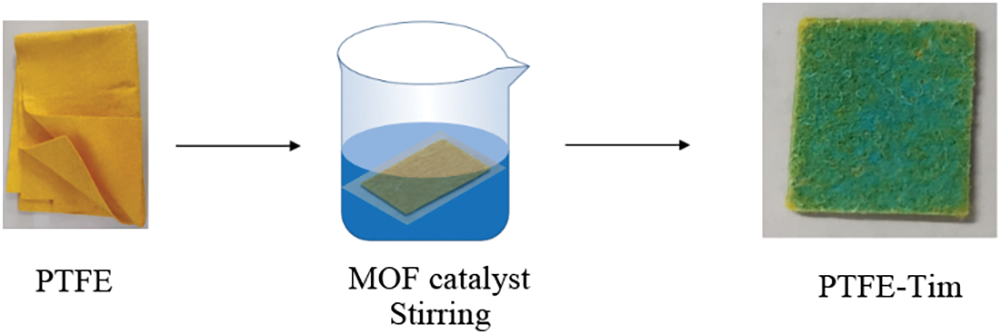
Figure 1: Catalyst supported by traditional impregnation method (PTFE-Tim)
(2) SA pretreatment
Compared with the traditional impregnation method, the SA pretreatment process was conducted prior to catalyst loading. The specific experimental method is as follows: a certain concentration of SA solution is prepared according to the experimental scheme, and the clean, dry PTFE filter material is immersed in the SA solution to ensure uniform soaking. After the predetermined time, the PTFE filter material deposited with SA is removed and dried in the oven at 80°C overnight, resulting in the PTFE filter material modified with SA (PTFE–SA). Using the same process as the traditional impregnation method, resulting in the composite filter material (PTFE–SA–MOF) pretreated with SA. The process flow for the preparation of PTFE–SA–MOF is shown in Fig. 2.
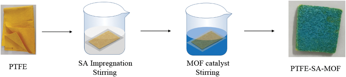
Figure 2: Process flow chart of SA pretreatment PTFE supported catalyst
(3) DA pretreatment
The dry and clean PTFE filter material was submerged in a DA solution (2 mg/mL, 10 mM Tris, pH 8.5) at 25°C for 24 h while being continuously stirred to perform polydopamine (PDA) coating. The filter material sample was washed three times with deionized water and dried in an oven at 80°C for 6 h to obtain a PTFE filter material with DA coating (PTFE–DA). Using the same procedure as the traditional impregnation method, resulting in a composite filter material (PTFE-DA-MOF) pretreated with DA. The preparation process is shown in Fig. 3.
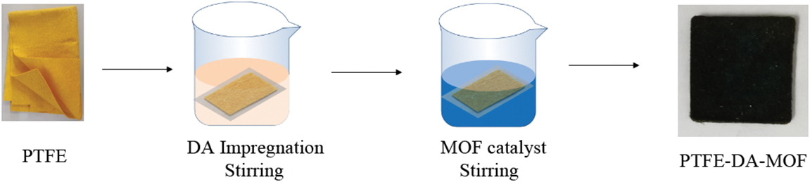
Figure 3: Experimental flow chart of DA modified PTFE supported catalyst
After the predetermined time, the excess water was removed by padding, rinsed repeatedly with distilled water, and then dried in a drying oven at 80°C overnight, to get three types of composite filter material.
The orthogonal test is a common method for obtaining the optimal level group under the influence of multiple factors and levels [34], which can save a significant amount of experimental time. In this study, a three-factor, two-level orthogonal test was applied to the traditional impregnation method, while a three-factor, four-level orthogonal test was used for SA deposition and DA modification pretreatment to investigate their effects on the debt ratio and firmness of the modified integrated PTFE composites.
According to the orthogonal experimental scheme defined by the single-factor experimental factor level, multiple sets of samples were prepared and tested following the same experimental process, resulting in the collection of orthogonal experimental data. The original data from the orthogonal experiment were processed to obtain the corresponding K, k, and R values. The K value and k value reflect the influence trend of the factor on this performance index. Here, Ki represents the sum of the test results corresponding to any level i (i = 1, 2, or 3) under a specific factor, and ki = Ki/n represents the arithmetic average of the results obtained when the factor is at level i in any column, where n is the number of occurrences of each level in that column. The R value (R = max {k1, k2, k3} − min {k1, k2, k3}, representing the range of ki on any column) indicates the degree of influence of this in on this performance index. A greater R value signifies a stronger influence of this factor on the performance index [35].
2.4.1 Evaluation Method of Filter Loading Rate
The loading rate refers to the mass ratio of the filter material before and after the catalyst is loaded. The catalyst loading effect of the integrated filter material is represented by the loading rate. This rate directly affects the catalytic activity of the integrated filter material. The higher the loading rate, the greater the mass ratio of the loaded catalyst. The calculation formula is shown in Eq. (1):
In the formula, η1 is the load rate, %; m1 and m2 are the weight of the filter before and after loading the catalyst, respectively, g.
2.4.2 Evaluation Method of Load Fastness of Integrated Filter Media
Loading firmness is another important criterion for evaluating the loading effect of the catalyst. The greater the loading firmness, the stronger the bond between the catalyst and the carrier, making it more difficult to peel off. The loading fastness of the catalyst was tested using the sandpaper wear method. The integrated composite filter material loaded with the catalyst was placed on 1500 mesh sandpaper, and the wear experiment was conducted under a weight load of 100 g. The wear distance was 10 cm, and the cycle involved moving back and forth.
The mass residual rate is used as an evaluation index of load firmness. It refers to the ratio of the mass of the integrated filter material after sandpaper wear to the mass of the integrated filter material before sandpaper wear. A higher mass residual rate indicates a greater mass of the integrated filter material after wear, less catalyst loss, and higher load firmness.
The calculation formula for the mass residual rate is shown in Eq. (2):
In the formula, η2 is the mass residual rate; M1 is the quality of the integrated filter material after the wear test, g; M0 is the quality of the integrated filter material before the wear test, g.
The primary factors influencing the loading rate of the impregnation method for the Mn-Cu-MOF catalysts include the impregnation time and the concentration of the mixed catalyst solution. Herein, a single-variable approach was employed to investigate the individual parameters affecting the loading rate.
Through a comparison of the literature and previous experiments, it was determined that the impregnation time of the filter material was 15–105 min, with data collected at 15-min intervals. The catalyst concentration was 0.4 g/L. The experimental results are shown in Fig. 4a. It can be observed from the figure that the loading rate of the PTFE filter material increases with the increase in impregnation time. After 60 min, the loading rate fluctuates and does not increase significantly. Therefore, the impregnation time levels selected for the subsequent orthogonal experiment to optimize the parameters were 45, 60, and 75 min, respectively.
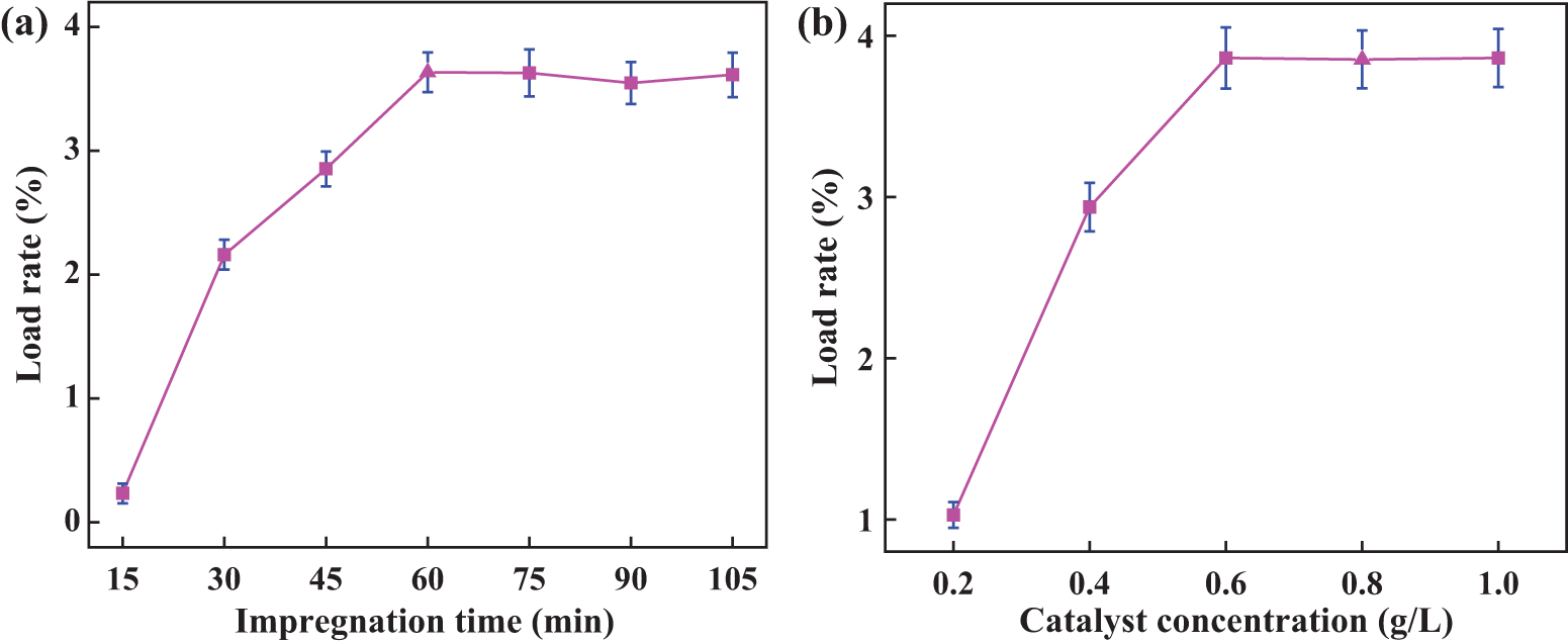
Figure 4: Loading rate of traditional impregnation method under different parameters (a) impregnation time; (b) Catalyst concentration
According to the impregnation time of the catalyst determined in the previous step, the impregnation time is 60 min, and the concentration of the catalyst is 0.2, 0.4, 0.6, 0.8, and 1.0 g/L, respectively. The experimental results are shown in Fig. 4b. The diagram shows that as the catalyst concentration increases, the loading rate also increases. When the catalyst concentration was 0.6 g/L, the loading rate reached its highest point. The loading rate essentially remained constant as the catalyst concentration increased. As a result, catalyst concentrations of 0.4, 0.6, and 0.8 g/L were chosen for the orthogonal experiment.
3.1.2 Optimization of Orthogonal Experimental Parameters
(1) Parameter selection
Considering the results of the single-factor experiment mentioned above, the catalyst impregnation times for the orthogonal experiments were selected as 45, 60, and 75 min, while the catalyst concentrations were 0.4, 0.6, and 0.8 g/L, respectively.
(2) Experimental design
From the analysis of the single-factor experimental results above, the factors and horizontal parameters of the traditional impregnation method are selected, as shown in Table 1.
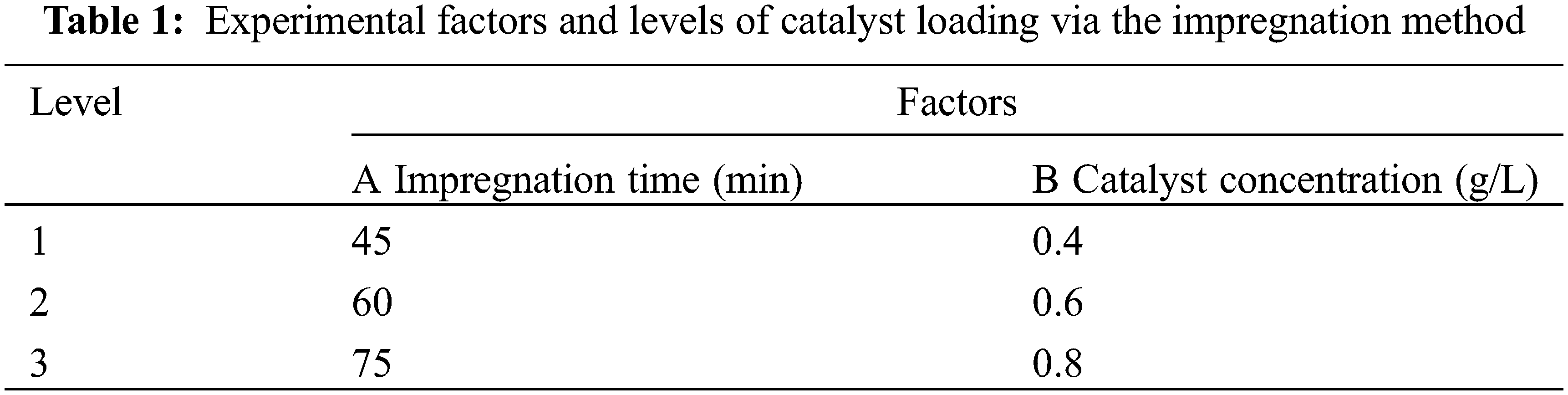
According to Table 1, the L9 (32) orthogonal experiment in Table 2 was selected to arrange the experiment. The obtained load rate value is the average of five experiments.
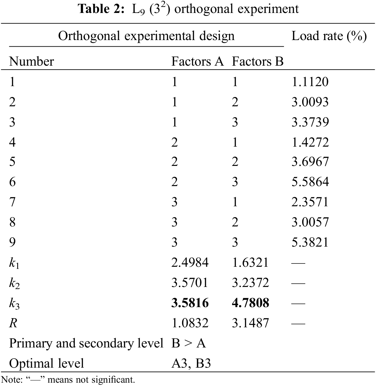
(3) Result analysis
The findings of the orthogonal trials indicate that the MOF catalyst concentration and the impregnation period have the greatest influence on the loading rate. The optimal experimental conditions for conventional impregnation of loaded catalysts were an impregnation time of 75 min and a catalyst concentration of 0.8 g/L.
SA, a natural polyanionic polysaccharide, is widely used in textile and cotton fabric printing and dyeing due to its excellent thickening, film-forming properties, and stability [36,37]. As a binder, SA can enhance the loading rate of the integrated filter catalyst. To further improve the loading rate and load stability of the catalyst, the PTFE filter material was functionalized and modified through SA deposition treatment before impregnation. Additionally, single-factor and orthogonal experiments were conducted to explore and optimize the experimental parameters of SA. The impact of SA addition on the loading rate and load fastness of the catalyst on the integrated filter material was discussed.
The concentration of the MOF catalyst, the PTFE impregnation time, the mass fraction of SA, and the SA deposition time are the primary factors influencing the sodium alginate deposition experiment. The results of the single-factor experiments are shown in Fig. 5.
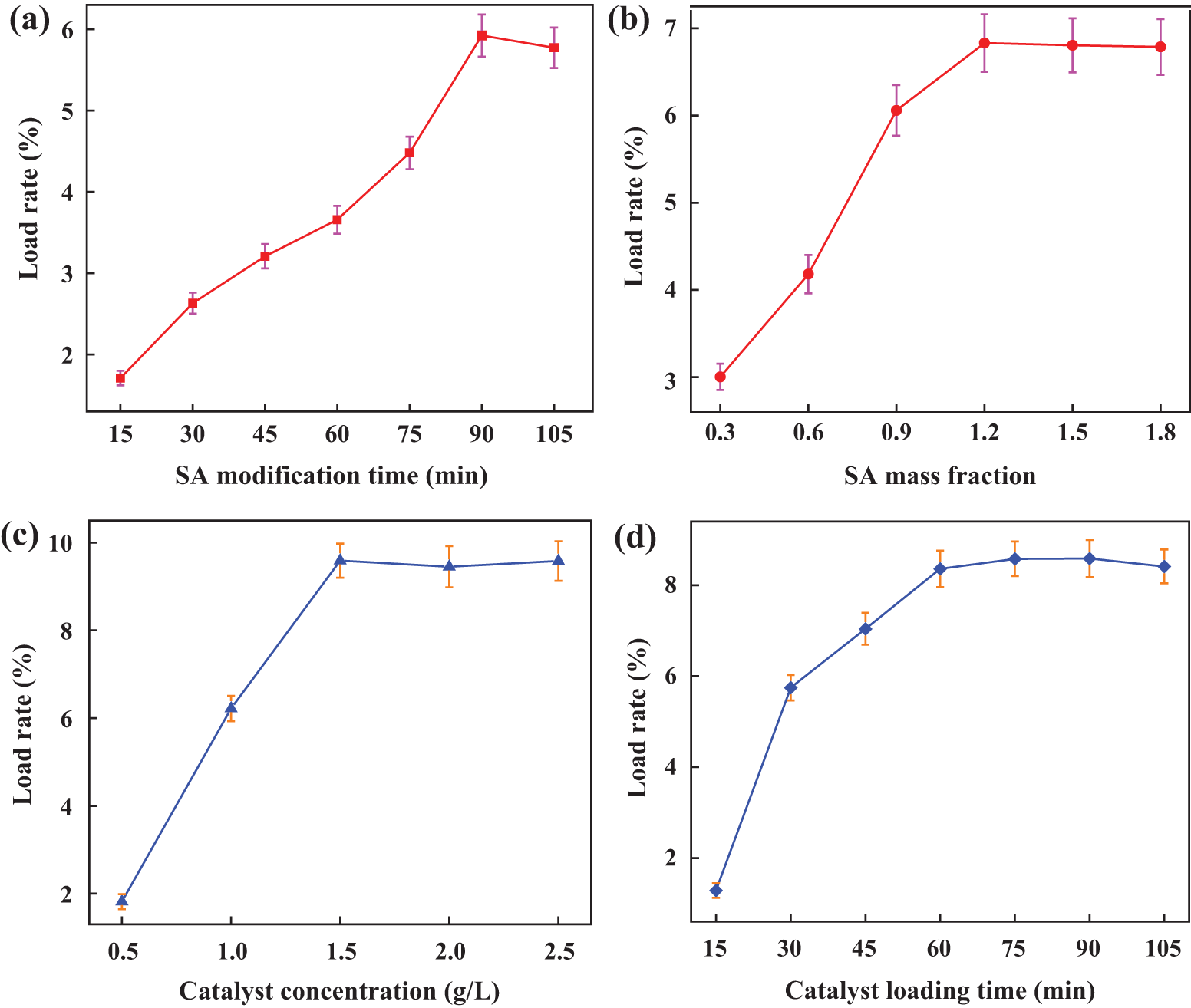
Figure 5: The loading rate of PTFE supported catalyst pretreated by SA under different parameters (a) The time of PTFE modified by SA, (b) The mass fraction of SA, (c) Catalyst concentration, (d) PTFE impregnation time of catalyst solution
The change in catalyst loading rate with SA deposition time is depicted in Fig. 5a. A lower catalyst loading rate results from short immersion times, likely due to the SA solution’s inability to fully deposit on the PTFE filter material. As deposition time increases, SA is completely deposited on the PTFE filter, leading to an increase in the loading rate. However, after the impregnation time exceeds 90 min, the catalyst loading rate does not increase significantly. Therefore, the SA modification times selected for the subsequent orthogonal experiment optimization are 75, 90, and 105 min.
Fig. 5b shows the influence of the mass fraction of SA on the load rate. Without the addition of SA, the loading rate of the catalyst was only about 2%. However, as the mass fraction of SA increases, the load rate also rises. When the mass fraction of SA reaches 1.2%, the load rate does not increase significantly. Therefore, the selected SA mass fraction levels for the next orthogonal experiment optimization are 0.9%, 1.2%, and 1.5%, respectively.
Fig. 5c shows the effect of catalyst concentration on the loading rate. Compared to the experimental results of the traditional impregnation method, the catalyst concentrations were set at 0.5, 1.0, 1.5, 2.0, and 2.5 g/L, respectively. As illustrated in Fig. 5c, as the catalyst concentration increases, the loading rate initially rises and then gradually stabilizes. When the catalyst concentration reaches 1.5 g/L, the loading rate attains its maximum value, after which it remains relatively constant. Therefore, the catalyst concentration levels selected for the subsequent orthogonal experiment optimization were 1.0, 1.5, and 2.0 g/L, respectively.
Fig. 5d shows how the length of the catalyst impregnation period affects the loading rate. The loading rate increases alongside the catalyst’s impregnation time. It tends to stabilize after the impregnation period exceeds 60 min. Consequently, 45, 60, and 75 min have been selected as the PTFE impregnation times for the upcoming orthogonal experiment optimization.
3.2.2 Optimization of Orthogonal Experimental Parameters
(1) Parameter selection
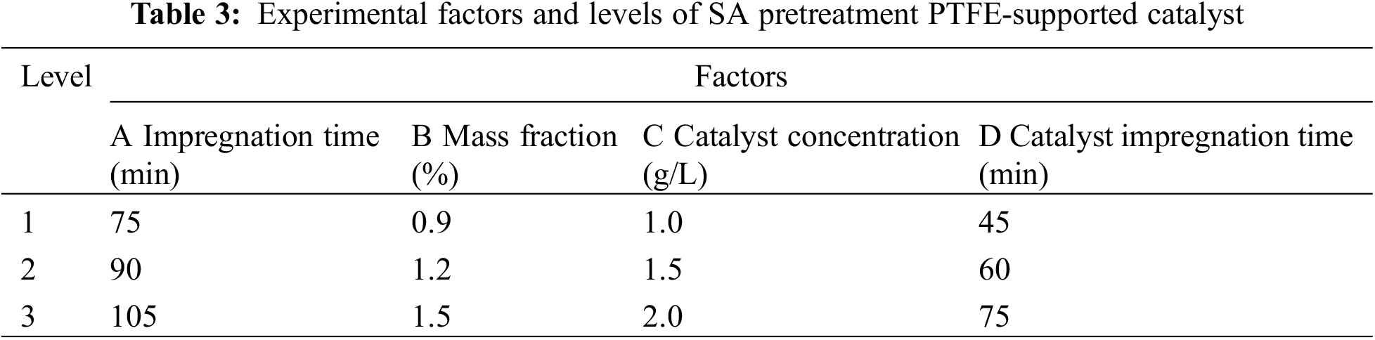
In light of the aforementioned single-factor experimental results, the parameters for the orthogonal experiment were selected: SA deposition times of 75, 90, and 105 min; SA mass fractions of 0.6%, 0.9%, and 1.2%; catalyst concentrations of 1.5, 2.0, and 2.5 g/L; and catalyst impregnation times of 45, 60, and 75 min.
(2) Orthogonal experimental design
Based on the analysis of the single-factor experimental results above, the factors and levels for this experiment are listed in Table 3.
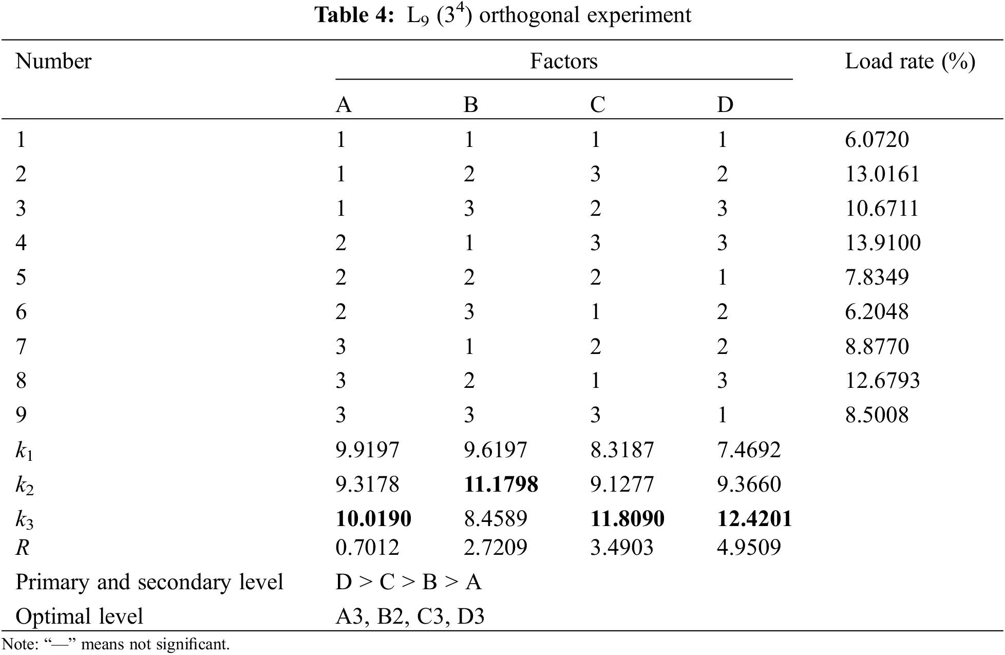
According to the factors and horizontal parameters of the orthogonal experiment in Table 3, the L9 (34) orthogonal experiment in Table 4 is selected to arrange the experiment. The obtained load rate and value are the average values after r testing five samples.
(3) Analysis of orthogonal experimental results
From the analysis of the orthogonal experimental results, the range results of the load rate and the relationships between the factors are shown in Table 4. The impregnation time of PTFE has the greatest influence on the load, while the modification time of SA has the least impact on the load rate. Additionally, the mass fraction of sodium alginate and the concentration of the catalyst exert minimal effects on the load rate, with the effect of catalyst concentration being slightly greater than that of the SA mass fraction. Therefore, the optimal experimental parameters for the SA-modified PTFE-supported catalyst experiment are as follows: SA impregnation time of 105 min, SA mass fraction of 1.2%, catalyst concentration of 2.0 g/L, and PTFE impregnation time of 75 min.
DA is a hormone and neurotransmitter commonly used in clinical settings, and it is also a key component of mussel adhesion proteins [38,39]. PDA produced by the self-polymerization of DA, has been widely utilized as a surface modifier owing to its excellent adhesion properties [40]. Inspired by the strong adhesion of mussels, we aimed to further enhance the interfacial activity and adhesion of the fiber surface in integrated filter materials. The surface activity of the PTFE filter material was modified through DA deposition treatment. The effects of DA pretreatment on the loading rate of the PTFE integrated filter material were investigated using single-factor and orthogonal test designs, and the impact of DA addition on the catalyst loading rate and loading firmness of the integrated filter material was examined.
As demonstrated in Fig. 6a, the modification time of DA was adjusted to 6, 12, 18, 24, and 30 h, respectively, according to the reported data [41]. The loading rate increased with the modification time of DA, but showed a downward trend after 24 h, which may be due to prolonged impregnation time leading to the oxidation of DA and a subsequent loss of adhesion. Therefore, the DA modification time levels were selected as 18, 24, and 30 h for the next orthogonal experiment optimization.
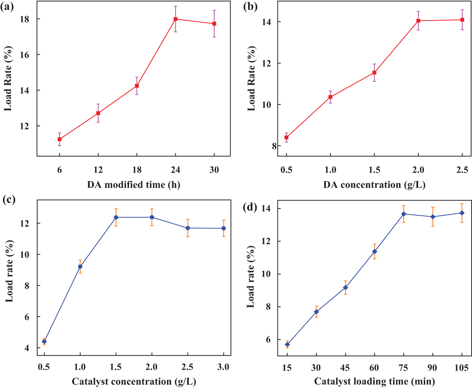
Figure 6: The loading rate of DA-modified PTFE supported catalyst under different parameters (a) The time of DA-modified PTFE filter material; (b) DA concentration; (c) Catalyst concentration; (d) PTFE impregnation time of catalyst
The concentrations of DA were 0.5, 1.0, 1.5, 2.0, and 2.5 g/L, respectively [41]. The experimental results are shown in Fig. 6b. As the DA concentration increases, the loading rate also increases. When the DA concentration reached 2.0 g/L, the loading rate gradually stabilized. Therefore, the DA concentration levels selected for the next orthogonal experiment optimization were 1.5, 2.0, and 2.5 g/L.
Fig. 6c shows the effect of catalyst concentration on the loading rate. When the catalyst concentration increases to 1.5 g/L, the loading rate stabilizes. Therefore, catalyst concentration levels of 1.0, 1.5, and 2.0 g/L were selected for the next orthogonal experiment optimization. Fig. 6d illustrates the effect of catalyst impregnation time on the loading rate. As time increases, the catalyst loading rate gradually rises, but does not increase significantly after 75 min. Therefore, the PTFE impregnation time levels of 60, 75, and 90 min were chosen for the next orthogonal experiment optimization.
3.3.2 Optimization of Orthogonal Experimental Parameters
(1) Parameter selection
In light of the single-factor experimental results mentioned above, the parameters for the orthogonal experiment were selected: DA modification time was set to 18, 24, and 30 h; DA concentration was set to 1.5, 2.0, and 2.5 g/L; catalyst concentration was set to 1.0, 1.5, and 2.0 g/L; and catalyst impregnation time was set to 60, 75, and 90 min.
(2) Orthogonal experimental design
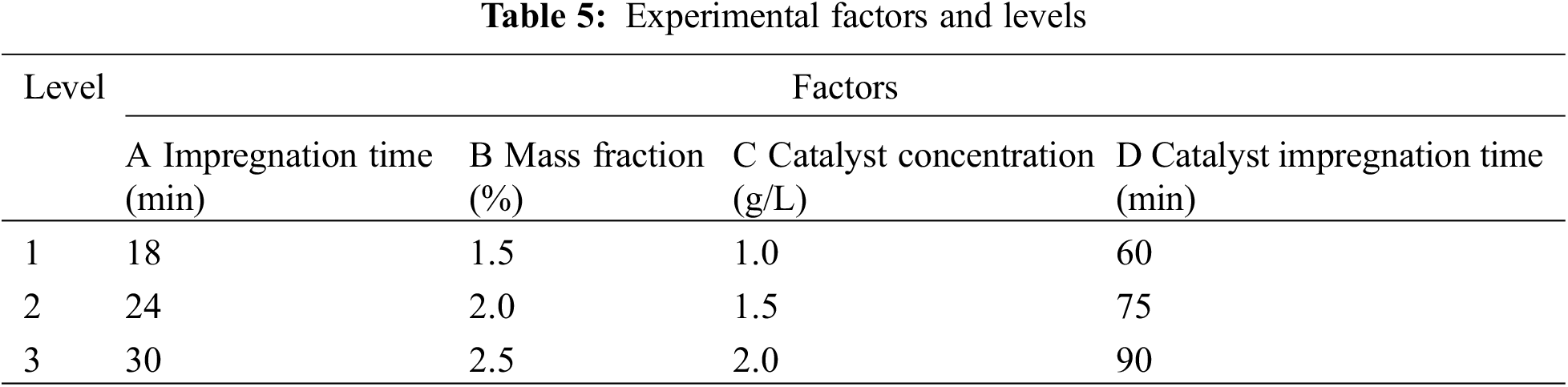
According to the analysis of the results from the single-factor experiment, the factors and levels for this experiment are presented in Table 5.
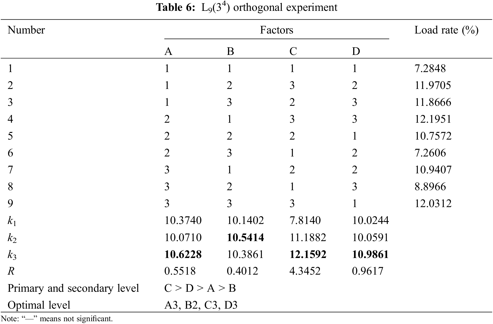
According to the factors and horizontal parameters of the orthogonal experiment in Table 5, the L9 (34) orthogonal experiment in Table 6 is chosen to conduct the experiment. In this experiment, the load rate value is the average obtained from testing 5 samples.
(3) Result analysis
Table 6 shows that the concentration of the catalyst has the greatest influence on the loading rate, while the concentration of DA has the least influence. The impregnation time of the catalyst and the modification time of DA have minimal effects on the loading rate. However, the influence of the catalyst’s impregnation time on the loading rate is slightly greater than that of the DA modification time. Therefore, the optimal parameters for the DA-modified PTFE-supported catalyst experiment are as follows: DA modification time of 30 h, DA concentration of 2.0 g/L, catalyst concentration of 2.0 g/L, and catalyst impregnation time of 90 min.
3.4 Evaluation of PTFE Filter Loading Effect Based on Optimized Process
The optimal catalyst loading process parameters identified through the aforementioned orthogonal experiments are summarized in Table 7.
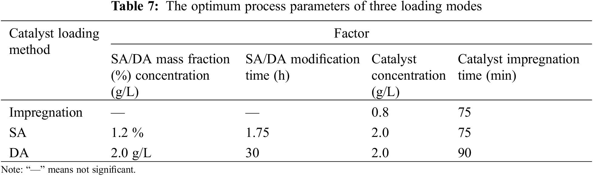
The optimal parameters for the three load modes are used to prepare the integrated filter material for denitrification and dust removal, and the load rate is calculated using Eqs. (1) and (2). The experimental results are shown in Fig. 7.
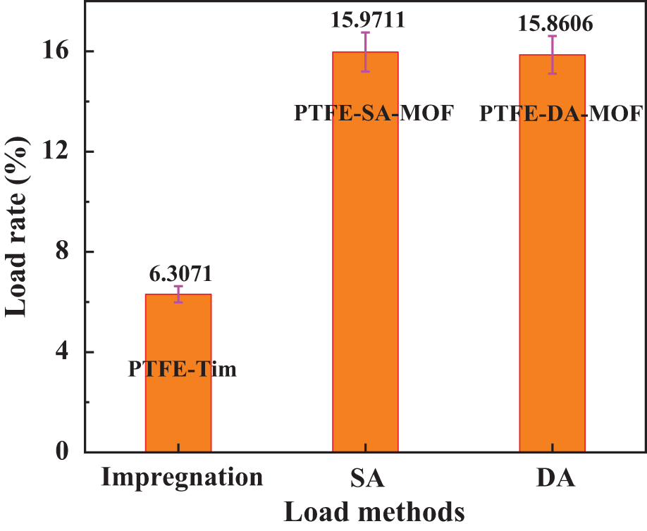
Figure 7: Optimal load rate of different load methods
It can be seen from Fig. 7 that the loading rate of the integrated filter material prepared by three different loading methods under the optimal experimental parameters is as follows: PTFE–SA–MOF > PTFE–DA–MOF > PTFE–MOF. The addition of the binder significantly improved the loading rate of the integrated filter material. The loading rates of PTFE–SA–MOF and PTFE–DA–MOF were 2.53 and 2.51 times higher, respectively, than that of the PTFE-Tim catalyst.
The integrated filter material prepared with the optimal parameters from various loading methods was used to test the load firmness of the catalyst and calculate the residual rate through the wear experiment scheme. The results are shown in Fig. 8.
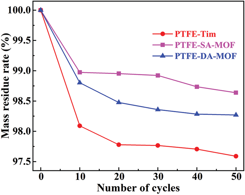
Figure 8: Evaluation of load fastness
It can be seen from Fig. 8 that the quality of the three integrated filter materials prepared by different methods has decreased significantly after 10 cycles of wear experiments, and the catalyst has obviously detached. Among them, the quality of PTFE-Tim has decreased the most, indicating that the simple impregnation method has low load fastness for the catalyst. In contrast, the quality of the PTFE–SA–MOF sample decreased the least, indicating that it has the highest load fastness. As the wear cycles increase, the residual mass of the filter materials prepared by the three loading methods decreases slowly. After 50 cycles, the residual mass of PTFE–SA–MOF is 98.64%, which is higher than the residual rate of PTFE–DA–MOF at 98.27% and the residual rate of PTFE-Tim at 97.59%. After 50 cycles of wear experiments, the residual mass gradually stabilized, indicating that PTFE–SA–MOF has the best load fastness.
Through the stability test mentioned above, it was found that the overall stability of PTFE filter material modified by DA and SA was significantly improved compared with the traditional impregnation method. For the SA-modified integrated filter material, the Mn–Cu–MOF material underwent an ion exchange reaction with the H+ ions on the alginate surface of the fiber and bonded to the fiber through a chemical bond. This chemical bond is considerably stronger than ordinary physical adsorption, allowing Mn2+ and Cu2+ to be firmly fixed on the fiber surface [42–44], thereby enhancing stability. For the DA-modified integrated filter material, this improvement may be attributed to the interactions and hydrogen bonding of the PDA formed after the polymerization of DA, which strengthened the binding between the Mn–Cu–MOF crystal particles and the fiber [45,46], thereby enhancing the wear resistance of the integrated filter material and constructing a microstructure with stable mechanical strength.
The integrated filter material for dust removal and denitrification technology (DRDt) was developed in this investigation using the conventional impregnation procedure. The loading rates of the integrated filter material were subsequently analyzed through orthogonal experimental methods to determine the optimal process parameters for each loading method. Single-factor experiments were conducted on the loading methods involving the traditional impregnation technique, SA, and DA pretreated PTFE composite filter material. The findings indicate that the loading rates follow the order: PTFE–SA–MOF > PTFE–DA–MOF > PTFE–MOF, while the load fastness is also ranked as PTFE–SA–MOF > PTFE–DA–MOF > PTFE–MOF. The loading rates for PTFE–SA–MOF and PTFE–DA–MOF are 15.97% and 15.86%, respectively, with load stability demonstrating stronger performance (98.64% and 98.27%) compared with PTFE-Tim. These loading rates are 2.53 and 2.51 times higher than those of PTFE-Tim. The Mn–Cu–MOF crystal particles were securely adhered to the surface of PTFE fibers through ion exchange, hydrogen bonding, and the adhesion of SA/DA. This enhances the bonding strength with the fibers and creates a microstructure with stable mechanical strength, significantly increasing both the loading rate and load stability. This study provides a robust experimental technique for advancing the integrated treatment of dust removal and denitrification, which is essential for achieving low-carbon environmental protection and high-quality treatment of industrial flue gas.
Acknowledgement: None.
Funding Statement: This study was financially supported by Natural Science Foundation of Anhui Provincial Department of Education (2022AH050337), State Key Laboratory of Safety and Health for Metal Mines (2022-JSKSSYS-04), the Project of National Key Research and Development Program (2022YFC3901405).
Author Contributions: Wei Dong: Prepare experiments, Data curation, Methodology, Investigation, Writing—review & editing. Fuping Qian: Resources, Writing—review & editing. Gang Li: Resources, Provide experimental ideas and experimental equipment. Shi’an Zhou: Participated experiments, Data curation. Lei Ding: Investigation. Qingda Gao: Participated experiments, Data curation. Xuemin Zeng: Methodology, Investigation. All authors reviewed the results and approved the final version of the manuscript.
Availability of Data and Materials: All data generated or analyzed during this study are included in this published article.
Ethics Approval: Not applicable.
Conflicts of Interest: The authors declare no conflicts of interest to report regarding the present study.
References
1. Sigsgaard T, Hoffmann B. Assessing the health burden from air pollution. Science. 2024;384(6691):33–4. doi:10.1126/science.abo3801. [Google Scholar] [CrossRef]
2. Kuntić M, Hahad O, Münzel T, Daiber A. Crosstalk between oxidative stress and inflammation caused by noise and air pollution—implications for neurodegenerative diseases. Antioxidants. 2024;13(3):266. doi:10.3390/antiox13030266. [Google Scholar] [PubMed] [CrossRef]
3. Tran HM, Tsai FJ, Lee YL, Chang JH, Chang LT, Chang TY, et al. The impact of air pollution on respiratory diseases in an era of climate change: a review of the current evidence. Sci Total Environ. 2023;898:166340. doi:10.1016/j.scitotenv.2023.166340. [Google Scholar] [PubMed] [CrossRef]
4. Mladenović M, Paprika M, Marinković A. Denitrification techniques for biomass combustion. Renew Sustain Energy Rev. 2018;82:3350–64. doi:10.1016/j.rser.2017.10.054. [Google Scholar] [CrossRef]
5. Chen K, Huang Y, Wang S, Zhu Z, Cheng H, Yuan Q. Integrated technology for dust removal and denitration of high-temperature flue gas in coal-fired power plants. Fuel. 2023;342:127687. doi:10.1016/j.fuel.2023.127687. [Google Scholar] [CrossRef]
6. Mateus G, Meiller M, Soukup K, Hornung A. Dust filtration influence on the performance of catalytic filters for NOx reduction. Emiss Contr Sci Tech. 2018;4(4):300–11. doi:10.1007/s40825-018-0102-x. [Google Scholar] [CrossRef]
7. Lyu F, Qiao J, Xu X, Zeng Y, Zhong Z, Xing W. Simple preparation of V2O5-WO3/TiO2/SiC catalytic membrane with highly efficient dust removal and NO reduction. Sep Purif Technol. 2024;343:127155. doi:10.1016/j.seppur.2024.127155. [Google Scholar] [CrossRef]
8. Kamble P, Unnikrishnan S, Khot S, Ananthanarayanan A, Banerjee D, Gopalakrishnan S, et al. Development of De-NOx selective catalytic reduction catalyst using V2O5–TiO2 supported on a ceramic filter candle. Int J Environ Stud. 2019;76(2):306–17. doi:10.1080/00207233.2018.1494926. [Google Scholar] [CrossRef]
9. Shin W, Lee KS, Kim KD, Park S, Choa Y, Park YO. Particulate removal characteristics of commercial-scale DeNOx catalyst cartridge coupled filter bags. Powder Technol. 2024;445:120071. doi:10.1016/j.powtec.2024.120071. [Google Scholar] [CrossRef]
10. Ahn S, Shim E, Kim Y, Bae YS, Eom H. Air filtration performance enhancement of PTFE foam-coated filters at high temperatures via secondary strongly adhering PTFE nanofiber coatings. Process Saf Environ Prot. 2022;162:914–22. doi:10.1016/j.psep.2022.04.067. [Google Scholar] [CrossRef]
11. Kadam VV, Wang L, Padhye R. Electrospun nanofibre materials to filter air pollutants–a review. J Ind Text. 2018;47(8):2253–80. doi:10.1177/1528083716676812. [Google Scholar] [CrossRef]
12. Li W, Liu H, Chen Y. Fabrication of MnOx–CeO2-based catalytic filters and their application in low-temperature selective catalytic reduction of NO with NH3. Ind Eng Chem Res. 2020;59(28):12657–65. doi:10.1021/acs.iecr.0c00131. [Google Scholar] [CrossRef]
13. Zhang B, Lu Y, Luo X, Wang W, Huang J, Lai Y, et al. Integration of dedusting and denitration in V2O5-WO3/TiO2/PTFE-based catalytic bag-filter materials: lab-and pilot-scale testing and development of SCR models. J Clean Prod. 2023;407:137122. doi:10.1016/j.jclepro.2023.137122. [Google Scholar] [CrossRef]
14. Shan L, Yin R, Xiao J, Wang H, Ma L, Li J, et al. Simultaneous removal of NOx and dust with integrated catalytic filter: interactions between NH3-SCR and filtration processes. Chem Eng J. 2023;458:141466. doi:10.1016/j.cej.2023.141466. [Google Scholar] [CrossRef]
15. Gao Y, Qian F, Sun Y, Wu Y, Wu S, Lu J, et al. A model for predicting the erosion rate induced by the use of a selective catalytic reduction denitrification technology in cement kilns flue gas. Fluid Dyn Mater Proc. 2023;19(8):1997–2011. doi:10.32604/fdmp.2023.026373. [Google Scholar] [CrossRef]
16. Javed MT, Irfan N, Gibbs BM. Control of combustion-generated nitrogen oxides by selective non-catalytic reduction. J Environ Manage. 2007;83(3):251–89. doi:10.1016/j.jenvman.2006.03.006. [Google Scholar] [PubMed] [CrossRef]
17. Abubakar A, Li C, Lin H, Gao S, Yu J. Simultaneous removal of particulates and NO by the catalytic bag filter containing V2O5-MoO3/TiO2. Korean J Chem Eng. 2020;37:633–40. doi:10.1007/s11814-020-0486-5. [Google Scholar] [CrossRef]
18. Jiang Z, Cheng T, Hu Y, Liu T, Qin K, Zhu C. Investigation of La-doped MnOx in PTFE filter bag for low-temperature selective catalytic reduction of NOx in cement industry flue gas with NH3. Mol Catal. 2024;556:113940. doi:10.1016/j.mcat.2024.113940. [Google Scholar] [CrossRef]
19. Xu X, Lyu F, Chen J, Zeng Y, Zhong Z, Zhang F, et al. Construction of V2O5-WO3/TiO2 nanocones catalyst layer on SiC ceramic membrane for efficient removal of NO and dust. Sep Purif Technol. 2023;323:124394. doi:10.1016/j.seppur.2023.124394. [Google Scholar] [CrossRef]
20. Boo JH, Kim E, Kwon BC, Seo MJ, Kim JM, Joo JB, et al. Addition of V2O5-MnO2/USY-zeolite catalyst in PTFE fiber for bag filter and its catalytic activity tests for NH3-SCR at low-temperature. J Ind Eng Chem. 2023;123:158–69. doi:10.1016/j.jiec.2023.03.032. [Google Scholar] [CrossRef]
21. Lee Y, Filliben JJ, Micheals RJ, Phillips PJ. Sensitivity analysis for biometric systems: a methodology based on orthogonal experiment designs. Comput Vis Image Underst. 2013;117(5):532–50. doi:10.1016/j.cviu.2013.01.003. [Google Scholar] [CrossRef]
22. Houtman AM, Speed TP. Balance in designed experiments with orthogonal block structure. Ann Stat. 1983;11:1069–85. [Google Scholar]
23. Yang K, Zhang X, Li M, Xiao Q, Wang H. Measurement of mixing time in a gas-liquid mixing system stirred by top-blown air using ECT and image analysis. Flow Meas Instrum. 2022;84:102143. doi:10.1016/j.flowmeasinst.2022.102143. [Google Scholar] [CrossRef]
24. Goicoechea HC, Olivieri AC. A comparison of orthogonal signal correction and net analyte preprocessing methods. Theoretical and experimental study. Chemometr Intell Lab. 2001;56(2):73–81. doi:10.1016/S0169-7439(01)00110-1. [Google Scholar] [CrossRef]
25. Lin E, Li X, Kure-Chu SZ, Li X, Xiao X. Effect of electrical parameters on the microstructure and corrosion resistance of anodized film of Mg-1Zn-1Gd alloy based on orthogonal experiment method. J Mater Eng Perform. 2023;33:1–12. [Google Scholar]
26. Han X, Yang S, Schröder M. Porous metal-organic frameworks as emerging sorbents for clean air. Nat Rev Chem. 2019;3(2):108–18. doi:10.1038/s41570-019-0073-7. [Google Scholar] [CrossRef]
27. Dong W, Zhou S, Ma Y, Chi D, Chen R, Long H, et al. N-doped C-coated MoO2/ZnIn2S4 heterojunction for efficient photocatalytic hydrogen production. Rare Met. 2023;42(4):1195–204. doi:10.1007/s12598-022-02196-7. [Google Scholar] [CrossRef]
28. Daglar H, Altintas C, Erucar I, Heidari G, Zare EN, Moradi O, et al. Metal-organic framework-based materials for the abatement of air pollution and decontamination of wastewater. Chemosphere. 2022;303:135082. doi:10.1016/j.chemosphere.2022.135082. [Google Scholar] [PubMed] [CrossRef]
29. Shi W, Li Z, Xu X, Yu Y, Ding X, Ju H. Protective graphite coating for two-dimensional carbon/carbon composites. Fluid Dyn Mater Proc. 2023;20(1):97–108. doi:10.32604/fdmp.2023.029028. [Google Scholar] [CrossRef]
30. Muñoz-Nuñez C, Hevilla V, Blázquez-Blázquez E, Zagora J, Placha D, Muñoz-Bonilla A, et al. Functionalization of chitosan films using essential oils by supercritical CO2 impregnation method for various applications. Carbohydr Polym Tech. 2024;8:100559. [Google Scholar]
31. Dolas H. Activated carbon synthesis and methylene blue adsorption from pepper stem using microwave assisted impregnation method: isotherm and kinetics. J King Saud Univ Sci. 2023;35(3):102559. doi:10.1016/j.jksus.2023.102559. [Google Scholar] [CrossRef]
32. Klimczak M, Kern P, Heinzelmann T, Lucas M, Claus P. High-throughput study of the effects of inorganic additives and poisons on NH3-SCR catalysts—part I: V2O5–WO3TiO2 catalysts. Appl Catal B-Environ. 2010;95(1–2):39–47. [Google Scholar]
33. Dong W, Qian F, Zhou S, Wu S, Gao Q, Chun T, et al. Synthesis of Cu/Mn bimetallic organic framework material and their catalytic performance for NH3-SCR. J Clean Prod. 2024;469:143182. doi:10.1016/j.jclepro.2024.143182. [Google Scholar] [CrossRef]
34. Collins LM, Dziak JJ, Li R. Design of experiments with multiple independent variables: a resource management perspective on complete and reduced factorial designs. Psychol Methods. 2009;14(3):202. doi:10.1037/a0015826. [Google Scholar] [PubMed] [CrossRef]
35. Wu X, Leung DY. Optimization of biodiesel production from camelina oil using orthogonal experiment. Appl Energ. 2011;88(11):3615–24. doi:10.1016/j.apenergy.2011.04.041. [Google Scholar] [CrossRef]
36. Siddaramaiah Swamy TM, Ramaraj B, Lee JH. Sodium alginate and its blends with starch: thermal and morphological properties. J Appl Polym Sci. 2008;109(6):4075–81. doi:10.1002/app.v109:6. [Google Scholar] [CrossRef]
37. Ehsan M, Razzaq H, Razzaque S, Bibi A, Yaqub A. Recent advances in sodium alginate-based membranes for dehydration of aqueous ethanol through pervaporation. J Polym Sci. 2022;60(16):2435–53. doi:10.1002/pola.v60.16. [Google Scholar] [CrossRef]
38. Gershman SJ, Assad JA, Datta SR, Linderman SW, Sabatini BL, Uchida N, et al. Explaining dopamine through prediction errors and beyond. Nat Neurosci. 2024;27(9):1645–55. doi:10.1038/s41593-024-01705-4. [Google Scholar] [PubMed] [CrossRef]
39. Channer B, Matt SM, Nickoloff-Bybel EA, Pappa V, Agarwal Y, Wickman J, et al. Dopamine, immunity, and disease. Pharmacol Rev. 2023;75(1):62–158. doi:10.1124/pharmrev.122.000618. [Google Scholar] [PubMed] [CrossRef]
40. Dimitrijevic NM, Rozhkova E, Rajh T. Dynamics of localized charges in dopamine-modified TiO2 and their effect on the formation of reactive oxygen species. J Am Chem Soc. 2009;131(8):2893–9. doi:10.1021/ja807654k. [Google Scholar] [PubMed] [CrossRef]
41. Wu Q, Razzak A, Bai H, Deng H, Ye Z, Zhu J. Dopamine concentration-dependent surface modification for gaining carbon fiber composites with enhanced interfacial adhesion. Compos Commun. 2022;29:101047. doi:10.1016/j.coco.2021.101047. [Google Scholar] [CrossRef]
42. Hecht H, Srebnik S. Structural characterization of sodium alginate and calcium alginate. Biomacromolecules. 2016;17(6):2160–7. doi:10.1021/acs.biomac.6b00378. [Google Scholar] [PubMed] [CrossRef]
43. Liang S, Cai W, Dang C, Peng X, Luo Z, Wei X. Synthesis of sodium alginate/phosphorus tetramethylmethyl sulfate biocomposite beads with exceptional adsorption rate for Cr(VI) removal. J Environ Chem Eng. 2023;11(2):109317. doi:10.1016/j.jece.2023.109317. [Google Scholar] [CrossRef]
44. Zhang H, Han X, Liu J, Wang M, Zhao T, Kang L, et al. Fabrication of modified alginate-based biocomposite hydrogel microspheres for efficient removal of heavy metal ions from water. Colloid Surf A. 2022;651(8):129736. doi:10.1016/j.colsurfa.2022.129736. [Google Scholar] [CrossRef]
45. Rezaie AB, Liebscher M, Ranjbarian M, Simon F, Zimmerer C, Drechsler A, et al. Enhancing the interfacial bonding between PE fibers and cementitious matrices through polydopamine surface modification. Compos Part B-Eng. 2021;217(4):108817. doi:10.1016/j.compositesb.2021.108817. [Google Scholar] [CrossRef]
46. Barclay TG, Hegab HM, Clarke SR, Ginic-Markovic M. Versatile surface modification using polydopamine and related polycatecholamines: chemistry, structure, and applications. Adv Mater Interfaces. 2017;4(19):1601192. doi:10.1002/admi.v4.19. [Google Scholar] [CrossRef]
Cite This Article
 Copyright © 2025 The Author(s). Published by Tech Science Press.
This work is licensed under a Creative Commons Attribution 4.0 International License , which permits unrestricted use, distribution, and reproduction in any medium, provided the original work is properly cited.
 Downloads
 Citation Tools