
 Submit a Paper
 Propose a Special lssue
 Open Access
REVIEW

A Review of Wind Turbine Blade Morphing: Power, Vibration, and Noise
Center for Turbulence Control, School of Mechanical Engineering and Automation, Harbin Institute of Technology (Shenzhen), Shenzhen, 518055, China
* Corresponding Author: Md. Mahbub Alam. Email:
Fluid Dynamics & Materials Processing 2025, 21(4), 657-695. https://doi.org/10.32604/fdmp.2025.060942
Received 13 November 2024; Accepted 27 February 2025; Issue published 06 May 2025
 View Full Text
 Download PDF
Abstract
Wind turbines play a vital role in renewable energy production. This review examines advancements in wind turbine blade morphing technologies aimed at enhancing power coefficients, reducing vibrations, and minimizing noise generation. Efficiency, vibration, and noise levels can be optimized through morphing techniques applied to the blade’s shape, leading edge, trailing edge, and surface. Leading-edge morphing is particularly effective in improving efficiency and reducing noise, as flow attachment and separation at the leading edge significantly influence lift and vortex generation. Morphing technologies often draw inspiration from bionic designs based on natural phenomena, highlighting the potential of biomimicry to improve aerodynamic performance and energy capture. Understanding fluid-structure interactions is critical to ensuring the lifespan, performance, and safety of wind turbine blades, which directly affect operational efficiency and noise levels. This review underscores the importance of comprehending the interdependencies between aerodynamics, vibration, and noise to guide future research and policy in sustainable wind energy development. By summarizing key advancements in the field, this paper serves as a valuable resource for researchers, policymakers, and industry leaders involved in wind energy technologies.Graphic Abstract
Keywords
Wind turbines convert kinetic energy from the wind into mechanical energy, which is then transformed into electricity, playing a crucial role in renewable energy production. They can be summarized and named based on different factors: rotation axis, torque produced, location, and power generation capacity (Fig. 1). Depending on the rotation axis of blades, wind turbines are classified as vertical axis wind turbine (VAWT) and horizontal axis wind turbine (HAWT), as illustrated in Fig. 1a. Particularly, conventional three-bladed horizontal turbines are the most common type of HAWT, used for large-scale energy production [1,2]. They have a higher power coefficient, large vibration, severe noise, and better performance in high-wind areas. The Archimedes spiral turbine is another example of HAWT that rotates around its horizontal axis. On the other hand, the VAWT has vertically arranged blades, low power coefficients, low vibrations, and low noises, typically used for small-scale production.
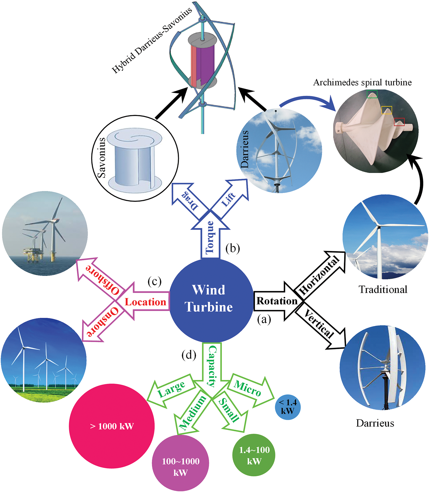
Figure 1: Classification of wind turbine based on (a) rotation axis, (b) torque produced, (c) location, and (d) power generation capacity
Wind turbines can also be classified based on the fluid dynamics involved in generating driving torque on the blades: specifically, ‘lift turbines’ and ‘drag turbines’ (Fig. 1b). In lift turbines, the driving force comes from lift generated on the blades (e.g., traditional, Darrieus, and Archimedes spiral turbines), while drag turbines rely on drag force to operate (e.g., Savonius turbine). The lift turbines can be both vertical axis (Darrieus) and horizontal axis turbines (Archimedes spiral turbines) while the drag turbines are mostly vertical axis turbines (Fig. 1b). The lift and drag turbines are suitable for low- and high-wind speeds, respectively. A hybrid of these two types is appropriate for intermediate wind speeds, known as a hybrid Darrieus-Savonius turbine.
Based on their location on the earth surface, wind turbines can be categorized as offshore (installed over water) or onshore (installed on land) (Fig. 1c). Offshore turbines typically provide more consistent large-scale power production but incur higher installation and maintenance costs. In contrast, although onshore turbines are generally less expensive to install and maintain, they have greater variability in power output. Additionally, wind turbines vary in their power production capacities. They can be classified according to the scale of power generation as micro-scale (<1.4 kW), small-scale (1.4–100 kW), medium-scale (100–1000 kW), and large-scale turbines (>100 kW) (Fig. 1d).
Regardless of the turbine type, blades are the primary component responsible for capturing wind energy and converting it into mechanical power, ultimately leading to electricity generation [3–5]. The blades play a crucial role in the overall performance, reliability, and cost of a wind turbine system [6,7]. Longer blades enhance energy yield by sweeping a larger area; however, they also become more flexible (with a longer aspect ratio) and face significant challenges due to high-speed airflow and fluid-structure interactions. These challenges can lead to reduced efficiency, violent vibrations, and excessive noise (Fig. 2a). Addressing these issues requires not only the use of advanced materials but also a comprehensive understanding of how fluid dynamics affects structural behavior and vice versa.
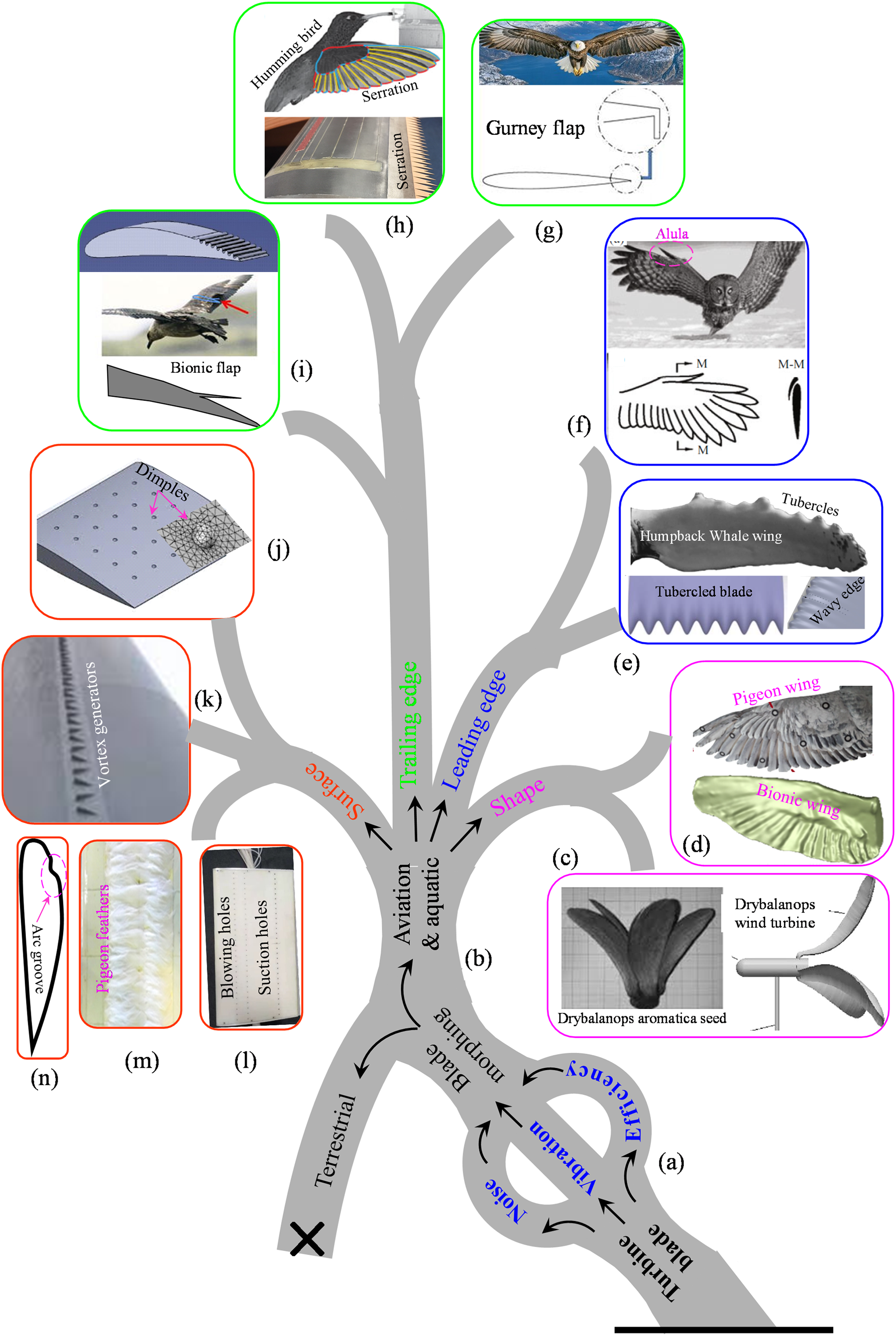
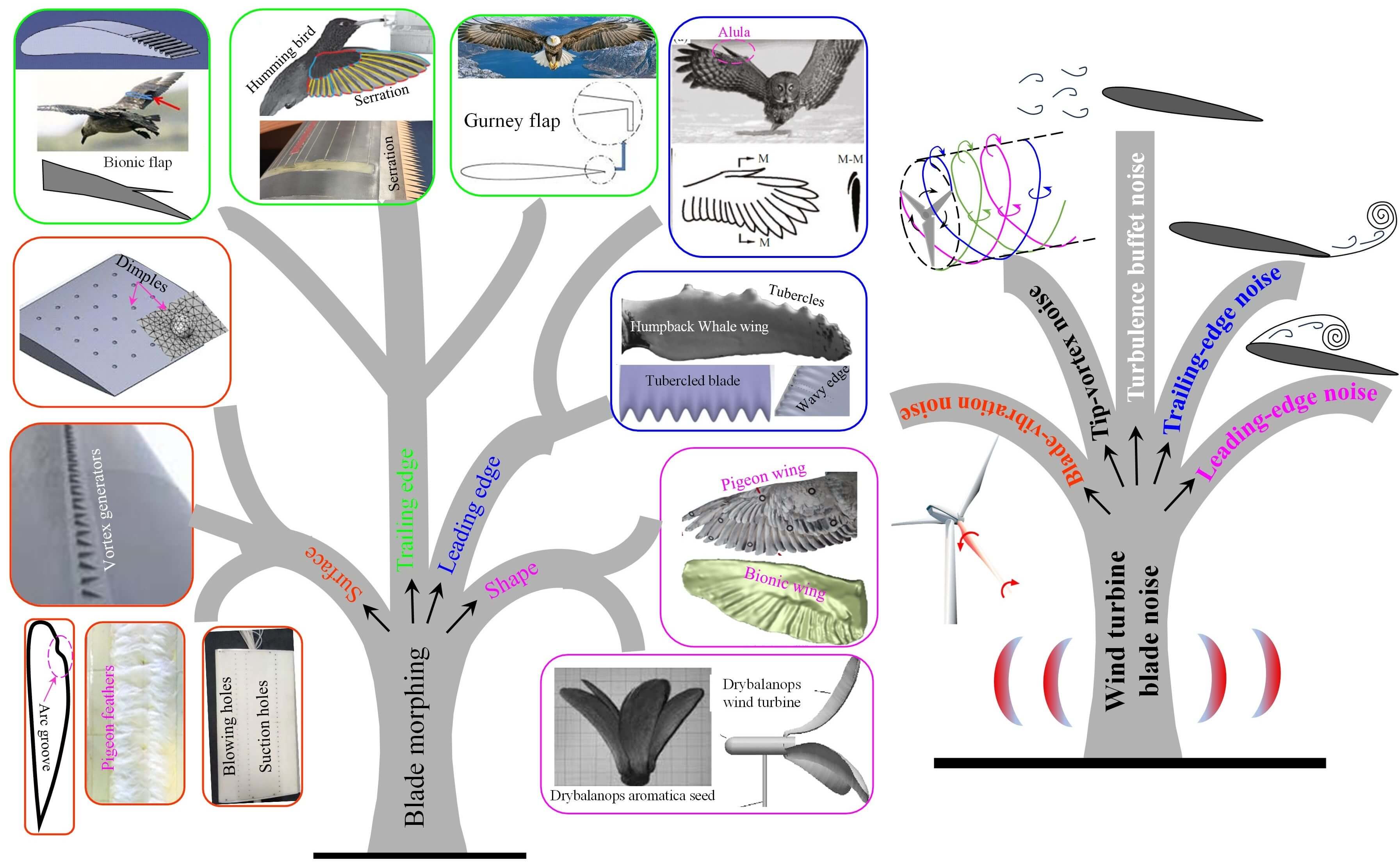
Figure 2: Wind turbine blade morphing tree illustrating key factors (efficiency, vibration, and noise) and morphing types (shape, leading edge, trailing edge, and surface morphing)
Researchers have employed various techniques to enhance the power coefficient (efficiency) of turbine blades as well as to reduce vibration and noise generation [8]. Given that aquatic or avian animals are generally faster than terrestrial animals, many researchers have exploited bionic morphing inspired by these species (Fig. 2b). The blade morphing techniques derived from aquatic and avian animals can be categorized into four: ‘shape morphing’ (Fig. 2c,d), ‘leading-edge morphing’ (Fig. 2e,f), ‘trailing-edge morphing’ (Fig. 2g–i), and ‘surface morphing’ (Fig. 2j–n). Blade shape morphing includes mimicking the structure of pigeon wings or the seeds of Drybalanops aromatica (Fig. 2c,d). The leading edge is particularly influential for power generation, as it affects primary flow separation, pressure on the suction side, and the formation of separation bubbles [9–11]. Bionic adaptations on the leading edge of the wings of aquatic and avian animals include features such as tubercles, alula, and serrations (Fig. 2e,f).
In contrast, the trailing edge plays a crucial role in managing secondary flow separation, pressure on the pressure side, and the quality of flow leaving the wing. Examples of trailing edge morphing include bionic flaps, Gurney flaps, and serrations (Fig. 2g–i). Finally, surface flow is controlled by mechanisms, such as vortex generators, feathers, dimples, grooves, blowing, and suction (Fig. 2j–n) [12–17].
Wind energy technology is rapidly evolving. As the demand for renewable energy sources grows, optimizing wind turbine performance is crucial to meet energy targets with minimal environmental impact. Blade morphing has the potential to optimize aerodynamic performance under varying wind conditions. Morphing technology presents challenges, including durability, control, and integration with existing turbine designs. Wind turbine design involves complex trade-offs between materials, aerodynamics, and structural integrity. A review paper is thus required, summarizing (i) the latest advancements in blade morphing technologies, (ii) multidisciplinary approaches needed for successful blade morphing, and (iii) how these adaptations can enhance energy capture, increase efficiency, and reduce noise. The topic of wind turbine blade morphing intersects various fields such as aerodynamics, materials science, mechanical engineering, and renewable energy policy. As such, the results published in the literature are not always cross-referenced.
This article aims to review the progress of research done on multiple interconnected aspects such as aerodynamics influencing the power coefficient, aeroelasticity affecting the vibration, and aero-acoustics addressing noise generation and its impact on both wildlife and human populations. Following the progress, researchers can create more effective and sustainable wind energy solutions and advocate for a more holistic approach to the design and development of wind turbine blades. By integrating these diverse aspects into the research framework, future studies can provide a more comprehensive understanding of wind turbine systems as a whole, paving the way for innovative designs and technologies that maximize the power coefficient, minimize environmental impact, and optimize the lifespan and safety of wind turbines. This review not only aims to direct upcoming research efforts but also serves as a guide for policymakers and industry leaders seeking to implement effective wind energy solutions in the quest for sustainable energy generation.
The efficiency of a turbine is defined by the power coefficient CP, which is the ratio of the power output P to the kinetic energy of the air available on the blade swept area. This can be expressed mathematically as:
where A = πR2 is the blade swept area, R is the blade length (rotor radius), ρ is the air density, and U is the approaching velocity of the air.
It is important to note that 100% extraction of energy from wind would result in a final velocity of zero, creating a situation where no flow occurs. Consequently, it is impossible to convert all the kinetic energy of air into electrical energy. Research has established that the efficiency of wind turbines cannot exceed 59.3%; surpassing this threshold would lead to flow reversal. This maximum efficiency limit is known as Betz’s limit, and it highlights the inherent constraints in harnessing wind energy effectively. A real-world wind turbine may capture (CP=) 25%–45% of the total available incoming wind energy. If this energy is harnessed for useful work, there may also be small additional losses for important power electronics, transformers, and power transmission.
Minimizing electricity costs is crucial to enhance the competitiveness of wind energy in the market. One effective approach is to continue the trend of developing larger wind turbines (Fig. 3). Due to factors such as space availability, noise concerns, and efficiency, offshore wind turbines are experiencing rapid growth in both size and power compared to their onshore counterparts. Offshore locations typically offer greater space for larger installations, allowing for more extensive turbine designs that can capture higher wind speeds and generate greater energy output. Additionally, since offshore wind projects are situated away from populated areas, they mitigate noise pollution issues that can arise with onshore turbines. These advantages make offshore wind energy increasingly attractive, driving significant advancements in turbine technology and size. Research indicates that the cost per kilowatt decreases with increased rated power [18–20]. This happens because the power generated by a wind turbine is theoretically proportional to the square of the blade length, while the blade mass increases with the cube of the length [21,22]. This relationship, known as the square-cube law, illustrates that blade mass grows more rapidly than energy output with increasing size, raising questions about a potential size limit for wind turbines [23]. However, advancements in design methodologies have shown that the mass of current turbine blades is increasing at an average exponent of 2.3, rather than the anticipated 3 [24]. Despite this efficiency improvement, the loads imposed by self-weight in larger turbines have become increasingly significant as the fundamental design has remained mostly unchanged.
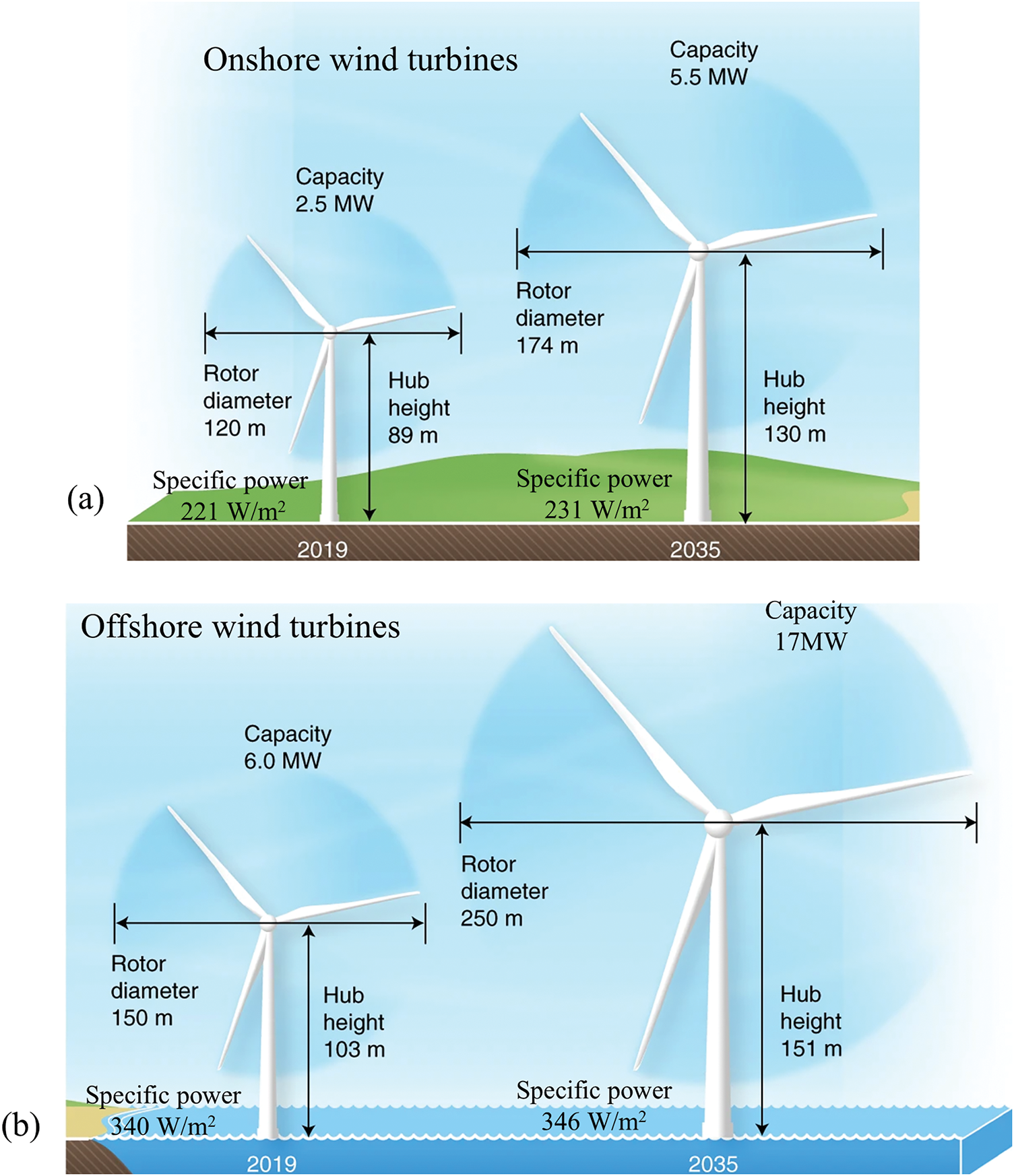
Figure 3: Illustration of increasing turbine size and capacity for (a) onshore wind turbine, and (b) offshore wind turbine (Adopted from [22])
Larger blades offer improved efficiency from both manufacturing and financial perspectives. Lightweight designs contribute to an overall reduction in mass-induced loads on the entire wind turbine system. While the rotor can account for about 20% of the total cost, minimizing its mass can significantly reduce material requirements, ultimately lowering the expenses related to the nacelle, tower, and foundations [25]. Consequently, as blade size increases, enhancing structural efficiency becomes increasingly crucial. The current blade design may have reached a point of maturity, and without substantial innovations, significant reductions in weight and cost may be unattainable [26]. Focusing on enhancing the structural efficiency of blades through innovative design concepts, it is possible to produce larger wind turbines that generate more energy, thereby reducing the overall cost of electricity.
The energy extraction efficiency of wind turbines is heavily influenced by rotation speed. If the speed is too low, a large volume of wind passes through the gaps between the blades without interacting, resulting in wasted energy. Conversely, when the rotation speed is excessively high, two issues arise: (i) the effective blade area starts to behave like a large, flat rotating disk, and (ii) the relative wind velocity increases along with the associated drag and lift forces [27]. To enhance wind turbine performance, optimizing the tip speed ratio is essential, as it is influenced by factors such as blade shape, number of blades, and overall design. Consequently, parameters like blade count, tip speed ratio, wind speed, and blade profile are critical in determining the system’s efficiency and effectiveness [28–33]. Designers constantly refine these parameters to achieve maximum power output at the minimal construction costs. These innovations lead to more compact, quieter, and efficient wind turbine systems that generate greater power from less wind.
The tip speed ratio (λ) is the ratio of the blade tip speed to the wind speed, and it plays a crucial role in determining the efficiency. A direct and significant correlation exists between λ and the turbine power coefficient. A higher tip speed enhances efficiency up to a certain point. However, beyond the optimal λ, efficiency may decline. For a standard three-blade horizontal wind turbine, the optimal λ value is 7–8, yielding a maximum CP = 0.45, which corresponds to rotational speeds of 10–20 rpm with a wind speed range of 6–12 m/s (Fig. 4). Notably, the optimal rotational speed of a wind turbine increases with wind speed but decreases with longer or more blades. On the other hand, a Darrieus lift turbine (a type of vertical axis turbine) achieves its maximum CP = 0.40 at an optimal λ ≈ 4 (Fig. 4). It suggests that vertical axis wind turbines have lower efficiency but perform better in lower wind speeds than horizontal axis wind turbines. Drag-type turbines, such as the Savonius turbine, exhibit a much smaller maximum CP (= 0.15) at an even smaller λ ≈ 1. Therefore, wind turbines in view of power coefficient can be sorted as drag-type vertical axis, lift-type vertical axis, and lift-type horizontal axis turbines.
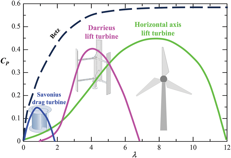
Figure 4: Comparison of power coefficient CP and tip speed ratio λ for different turbines
Turbine blade morphing refers to the blade structure change in response to operational demands, optimizing the power coefficient, reducing vibrations or weakening noise levels, and enhancing the overall viability of renewable energy sources. Major changes can occur through modifications to the blade shape, leading edge, trailing edge, or surface.
The morphed shape of a wind turbine blade is the intentional change in the blade geometry to enhance aerodynamic performance and overall efficiency [34–36]. Innovations such as those by Gao et al. [37], who developed bionic wind turbine blades inspired by the airfoil of owl wings and the herringbone groove structure of owl feathers (Fig. 5a,b), illustrate how biomimicry can enhance the turbine power coefficient [38–41]. The unique features of owl wings, including a specially curved leading edge and herringbone groove structures on the feathers, allow these bionic blades to optimize airflow. They found that the owl-inspired bionic blades provide a higher CP, up to 10.53% higher than that of a traditional prototype blade for λ = 6–10 (Fig. 5c). The larger leading-edge curvature and herringbone groove structures of bionic blades lead to larger flow velocity and smaller pressure on the suction surface (Fig. 5d).
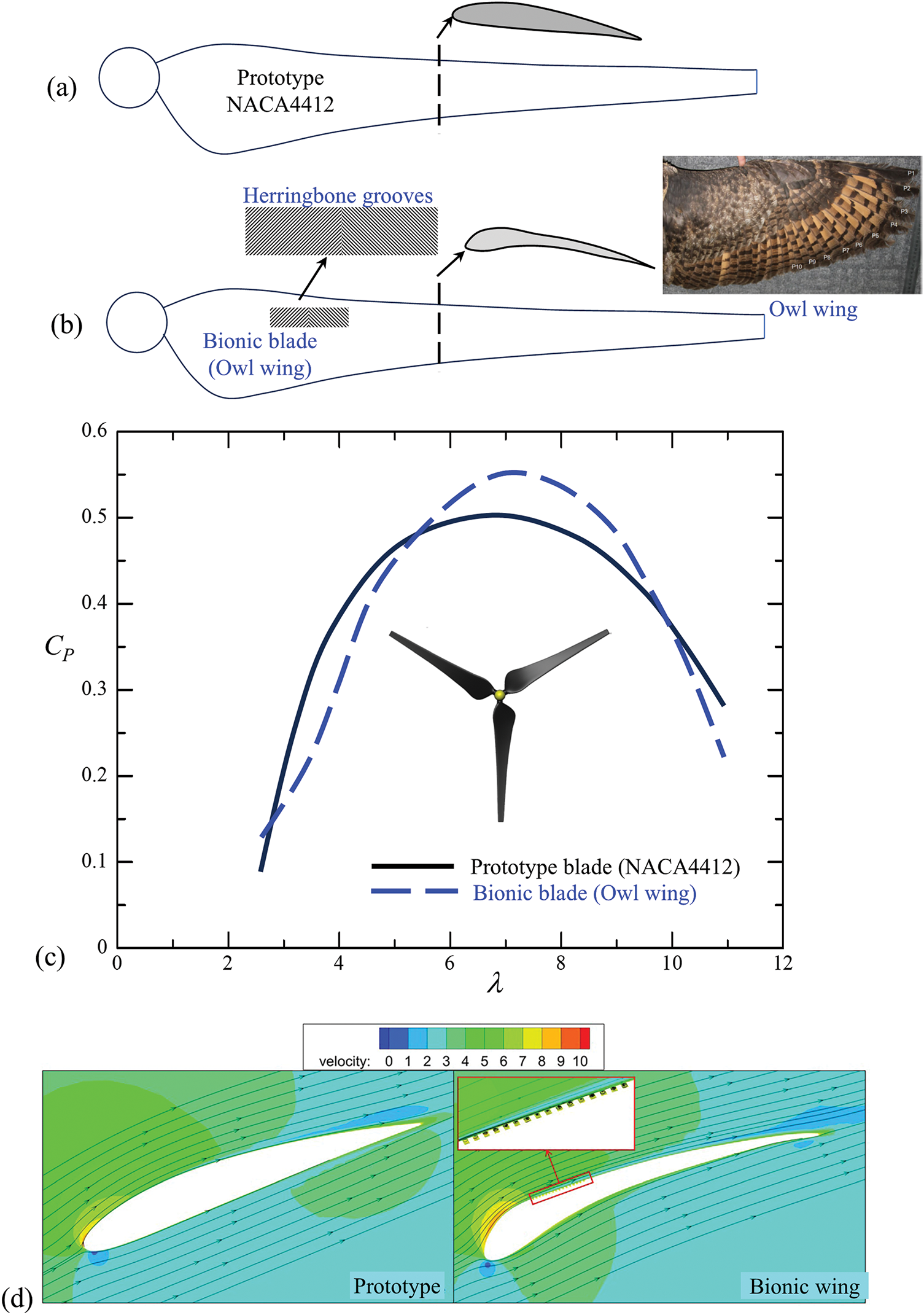
Figure 5: (a) Prototype blade (NACA4412). (b) Bionic blade traced from owl wing including the herringbone grooves. (c) Dependence of power coefficient CP on tip speed ratio λ for the prototype and bionic blades. (d) Streamlines and velocity contours at 20% section for λ = 8. Adopted with permission from [37]. Copyright © 2021, AIP Publishing
Chu et al. [42] developed a blade shape mimicking the seeds of Dryobalanops aromatica, which significantly differs from the traditional wind turbine blades (Fig. 6). They compared the performance of the Dryobalanops-inspired turbine and a scaled version with the tapered- and twisted-S826 turbine by Krogstad et al. [43]. Although the maximum CP of both Dryobalanops turbine and its scaled version is lower than that of the S826 turbine, the corresponding λ value at the maximum CP decreases from 6 for the S826 turbine to 3.5 for the scaled Dryobalanops turbine and then to 1.5 for the Dryobalanops turbine. This indicates that the latter two designs are more suited for low-speed wind environments, functioning as low-speed turbines without a significant drop in CP, particularly for the Dryobalanops turbine. This further implies that the cut-in speed for the Dryobalanops turbine is small.
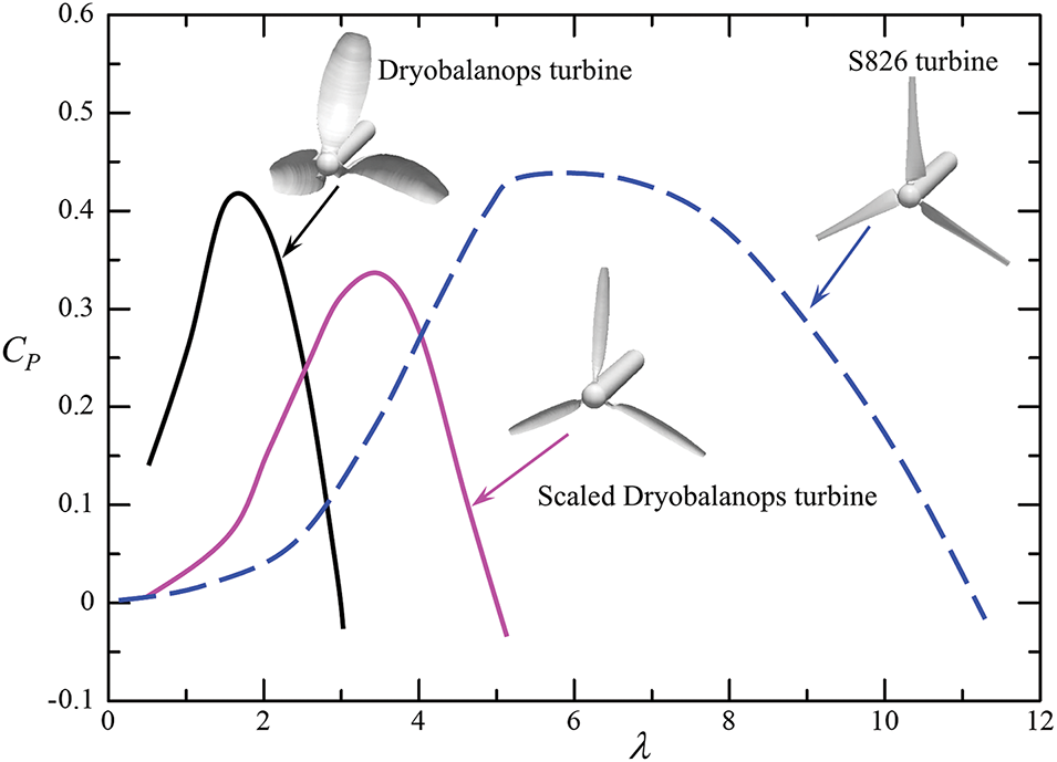
Figure 6: Performance coefficient CP curves for Dryobalanops-inspired (bionic) turbine, scaled Dryobalanops turbine and S826 airfoil turbine. Adopted with permission from [42]. Copyright © 2017, Elsevier
Ge et al. [39] developed a bionic airfoil inspired by the wing of the long-eared owl, which effectively delayed stall angles and enhanced the maximum lift coefficient of wind turbine blades. Similarly, Xu et al. [33] introduced a bionic groove structure into the blade tip design, inspired by the drag reduction characteristics of mantis shrimp. Krishnan et al. [38], Tian et al. [44] and Wang et al. [45] focused on the bionic design of small horizontal axis wind turbine blades using insights from biological airfoils, demonstrating that these bionic blades outperformed standard blades in efficiency tests. Additionally, Zhang et al. [46] identified that the three bionic airfoils derived from the long-eared owl achieved a high lift-to-drag ratio, corresponding to the wing’s cross sections at 20%, 40%, and 60%. These studies highlight the potential of biomimetic designs in enhancing wind turbine performance.
Controlling the flow over the leading edge of wind turbine blades presents an innovative approach to enhancing the power coefficient of these systems [47]. A fascinating case study that exemplifies this technique is the design of the pectoral flippers of the humpback whale, which exhibit a high aspect ratio planform that gently curves toward the distal end (Fig. 2e). Unlike traditional aerodynamic designs that favor a smooth, streamlined leading edge, the humpback whale’s flippers are characterized by the presence of large, rounded bumps known as tubercles. These tubercles create a serrated edge that disrupts the airflow in a way that offers several performance advantages. Butt et al. [48] conducted an experimental investigation on NACA0021 and NACA4412 blades with and without tubercles on the leading edge. They found that the lift coefficient of the NACA0021 with tubercles is higher at high angles of attack than that of the tubercle-free blade at Re = 1.2 × 10⁵ – 1.69 × 10⁵. The benefit of tubercles nevertheless faints at high Reynolds numbers. Hrynuk et al. [49] experimentally observed that the leading-edge tubercles on Humpback whale flippers act as control elements that delay dynamic stall, contributing to improved aerodynamic performance at high angles of attack [50–52].
Varying the amplitude and wavelength of serration on the leading edge, Johari et al. [50] identified a decrease in lift and an increase in drag for morphed blades with attack angles less than 20° compared to the plain blade (Fig. 7a). For angles greater than 20°, the lift of the morphed blades increases up to 50% with little or no drag penalty (see also [53–55]). The morphed blade exhibits a softer stall than the plain blade. Interestingly, the serration amplitude significantly influences the performance of the morphed blade, whereas the wavelength effect is minimal. The associated fluid dynamics could be understood from the tuft flow visualization shown in Fig. 7b,c. For the plain blade at α = 12° (before stall), the flow is attached along the first three-quarters of the blade before separating toward the tail (Fig. 7(b1)). When the amplitude of the serration increases to 0.12c, the separation shifts upstream, yet the flow remains attached for a longer distance at the node (peak) section compared to the saddle (trough) section (Fig. 7(b2, b3)). At a high α = 24°, beyond the stall condition, the flow on the plain blade separates from the leading edge, resulting in intense flow reversal across most of the surface (Fig. 7(c1)). The introduction of serrations makes the reversal flow highly three-dimensional (Fig. 7(c2)), leading to the generation of the streamwise vortices from the trough (see the inset in Fig. 7a). With a greater amplitude of serration, the flow stays attached for an extended distance at the node section (Fig. 7(c3)). This phenomenon explains why the lift coefficient of the serrated blade is greater than that of the plain blade at α > 20°.
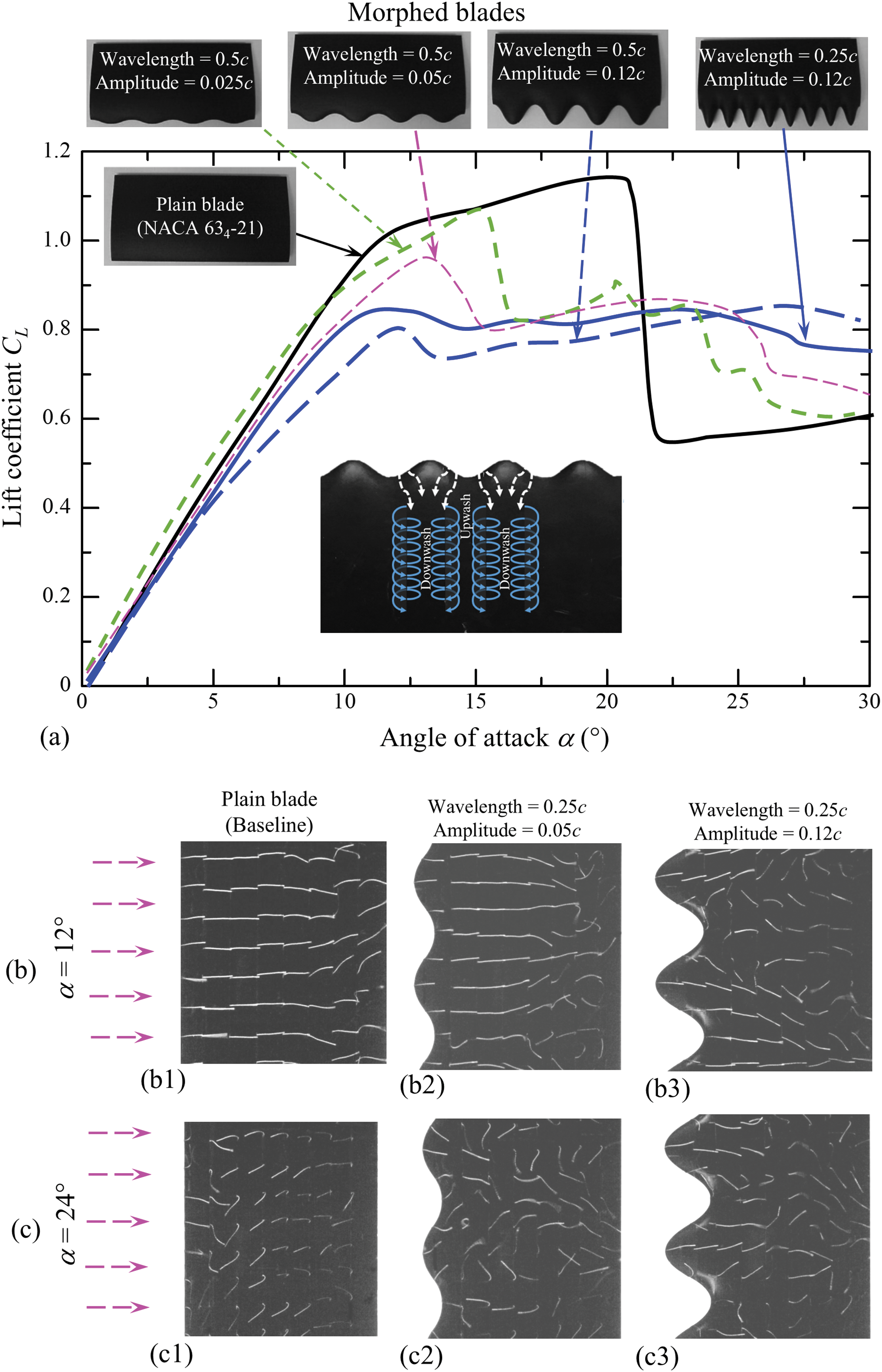
Figure 7: (a) Lift coefficient CL curves against angle of attack α for morphed blades with different amplitudes and wavelengths of serration at the leading edge. (b, c) Near surface flow on the blade for α = 12° and 24°. Leading-edge morphing. Adopted with permission from [51]. Copyright © 2014, AIP Publishing
Zhao et al. [56] utilized large-eddy simulations to analyze the performance of a blade with a wavy leading edge, featuring a wave amplitude of 0.015c and wavelength of 0.11c. Their findings revealed that the enhanced performance of this blade results from intense streamwise vortices generated by the leading-edge protuberances, which ferry the fluid momentum from a saddle to the neighboring nodes (see the inset in Fig. 7). Jones et al. [57] observed a sudden increase in lift at certain critical high angles of attack when a rigid flap was attached to the leading edge of the airfoil. They found that the leading-edge flap effectively trips the boundary layer to remain attached, preventing the formation of a laminar separation bubble. Wong et al. [58] and Rinoie et al. [59] also employed a leading-edge flap on an airfoil, successfully suppressing the bubble burst and increasing both stall angle and maximum lift.
There are several methods of trailing edge morphing, including the use of flexible bionic flaps, Gurney flaps, serrations, or blunt tails [60–64]. Liu et al. [64] made the blade trailing edge blunt, thickening the trailing edge as h = 0.015c, 0.03c, 0.045c, and 0.06c on the upper side (δ = 0) only, lower side (δ = 1) only and both sides (δ = 0.5), along with additional configurations at δ = 0.25 and 0.75. The δ ≠ 0.5 represents asymmetric modifications (Fig. 8a). For a symmetric thickness δ = 0.5, the trailing edge thickens uniformly on both sides with increasing h. Compared to the baseline case (original), both lift and drag coefficients of the airfoil grow with increasing h and decreasing δ (<0.5). On the other hand, when δ > 0.5, the impact of h prevails for large angles of attack (AOA) only, leading to an increased lift without appreciable changes in drag. Consequently, the lift-to-drag ratio does not improve before the stall but does enhance after the stall.
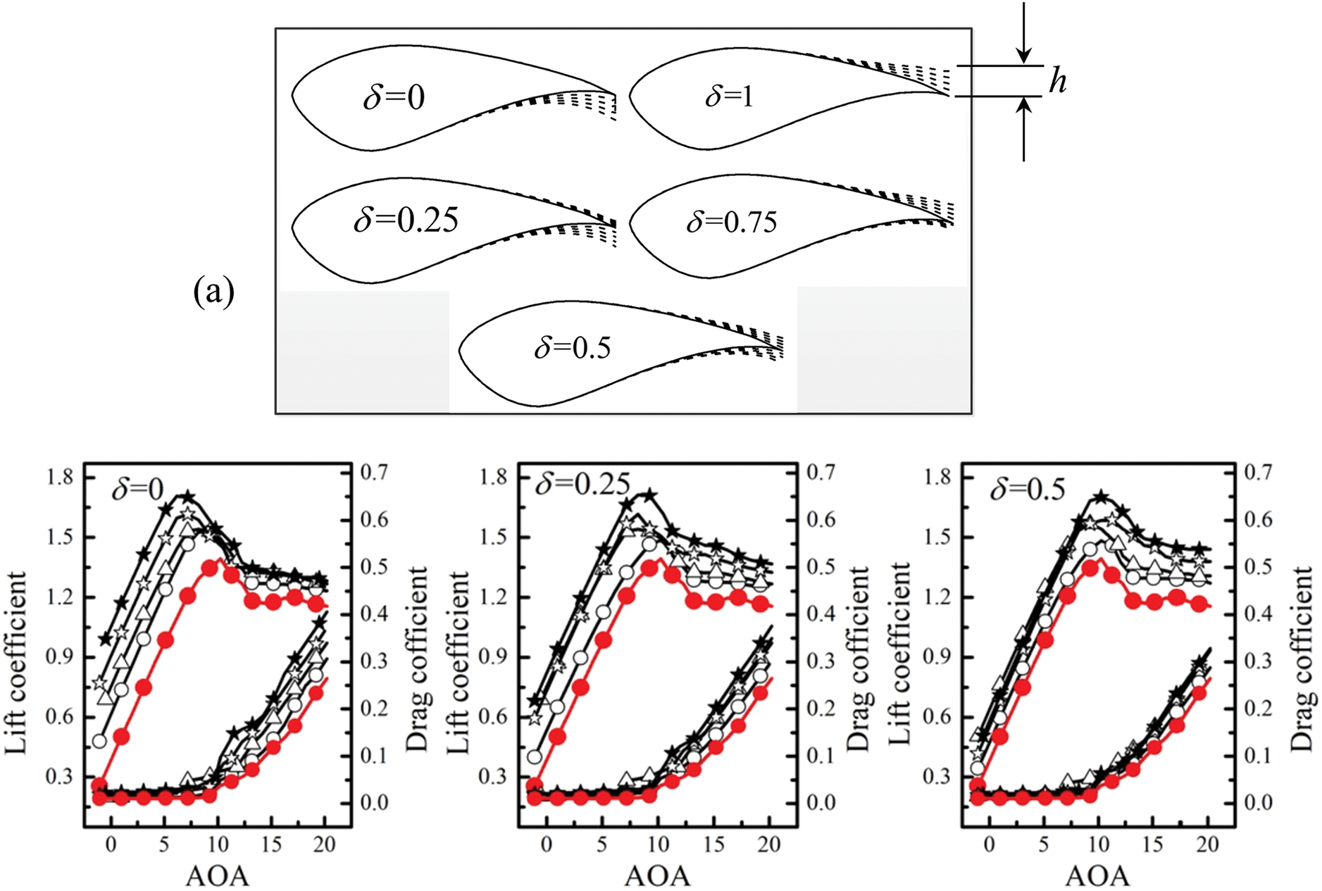
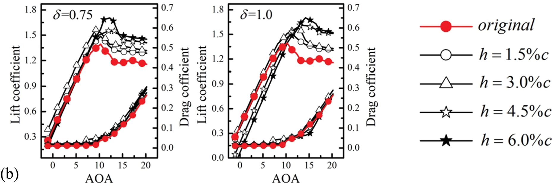
Figure 8: (a) Definition of on trailing-edge thickness h and asymmetry factor δ for S814 blade turbine. (b) Dependence of lift and drag coefficients on trailing-edge thickness h and asymmetry factor δ. Trailing-edge morphing. Adopted with permission from [64]. Copyright © 2020, Elsevier
A Gurney flap (GF) set on the lower side of the trailing edge can improve the performance of a blade [65,66]. On the other hand, a bionic flap (BF) applied to the upper side of the trailing edge can delay stall and enhance post-stall lift [67–70]. Wu et al. [71] examined the effects of using only the BF, only the GF, and a combination of both on the trailing edge of a NACA2414 blade, as illustrated in Fig. 9. The BF primarily increases the lift at the post-stall angles while the GF effectively boosts lift at pre-stall angles. In contrast, the combined use of both bionic and Gurney flaps (BG & GF) enhances lift across all angles of attack. Akhter et al. [72] conducted a three-dimensional simulation to investigate the effect of trailing-edge morphed blades on a two-bladed, fixed-pitch, stall-regulated, horizontal-axis wind turbine. Using the baseline S809 airfoil, they geometrically modified the aft 30% of the chord, implementing a smooth, seamless camber deflection. The degree of morphing was quantified by the trailing-edge deflection angle, defined as the angle formed by the intersection of the deflected chord line with the original chord at 70% of the total chord length from the leading edge. The results showed a 40% reduction in cut-in speed, a 367% increase in thrust, and a 600% increase in power.
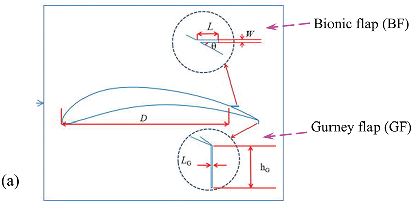
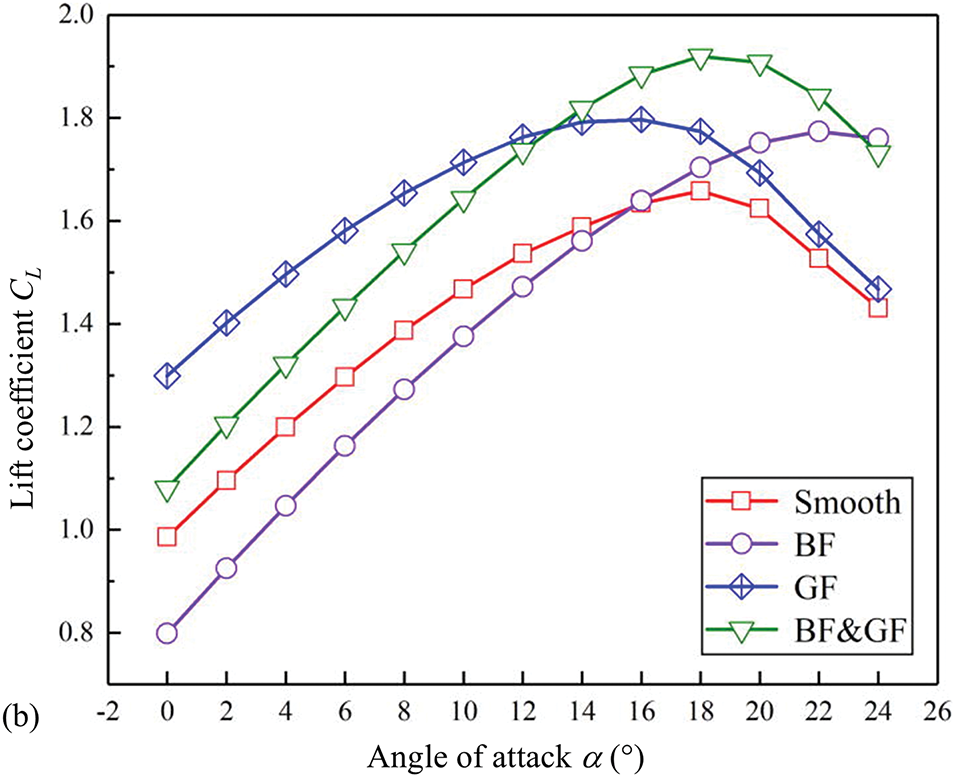
Figure 9: (a) Definition of bionic flap and Gurney flap. (b) Dependence of lift coefficient on angle of attack α for blades with bionic flap (BF) only, Gurney flap (GF) only, and both BF and GF (BF & GF). Reproduced from Wu et al. [71]. Trailing-edge morphing. Adopted with permission from [71]. Copyright © 2022, AIP Publishing
Researchers altered wind blade surface by integrating dimples [13,14,73], grooves [15,16], vortex generators [35], texturing [74], jets [75,76], feathers [77], etc., into the blades. The primary goals of this technology are to optimize aerodynamic characteristics, reduce noise, and improve energy capture across varying wind conditions.
Dimples: Dimples on blade surfaces are small, spherical indentations or protrusions that are intentionally incorporated into the turbine blade profile. These features are inspired by biomimicry and properties observed in nature, such as the design of golf balls and shark bodies [78–80]. Dimples not only enhance the turbulence of flow on the surface but also improve the mechanical strength of the turbine blades. Sedighi et al. [14] conducted a numerical study to assess the effects of surface dimples on the torque and power output of V47-660 kW horizontal axis wind turbine (Fig. 10a). They incorporated three rows of spherical dimples on the suction surface at positions 0.2c, 0.4c, and 0.6c from the leading edge, varying the dimple radius r and pitch distance pd between the dimples (Fig. 10b). The findings revealed that a decrease in r from 70 mm to 25 mm leads to an increase in torque for pd ≤ 30. Yet, the produced torque with r = 70 mm and 50 mm is lower than that of the original, no-dimple blades. Notably, the morphed blades provide greater torque than the original blades when (r, pd) = (25 mm, 20 cm) and (15 mm, 30 cm). The former condition yields higher torque than the latter and hence can be deemed optimal for rated wind speeds. For this optimal scenario, the torque increases by 16.08% compared to the blades without dimples. The enhanced performance is attributed to the ability of the surface dimples to delay the flow separation (Fig. 10(c1, c2, c4, c5)) or even eliminate the flow separation (Fig. 10(c3, c6)). In other words, the flow remains attached on the blade surface for a longer chord length for the dimpled cases.
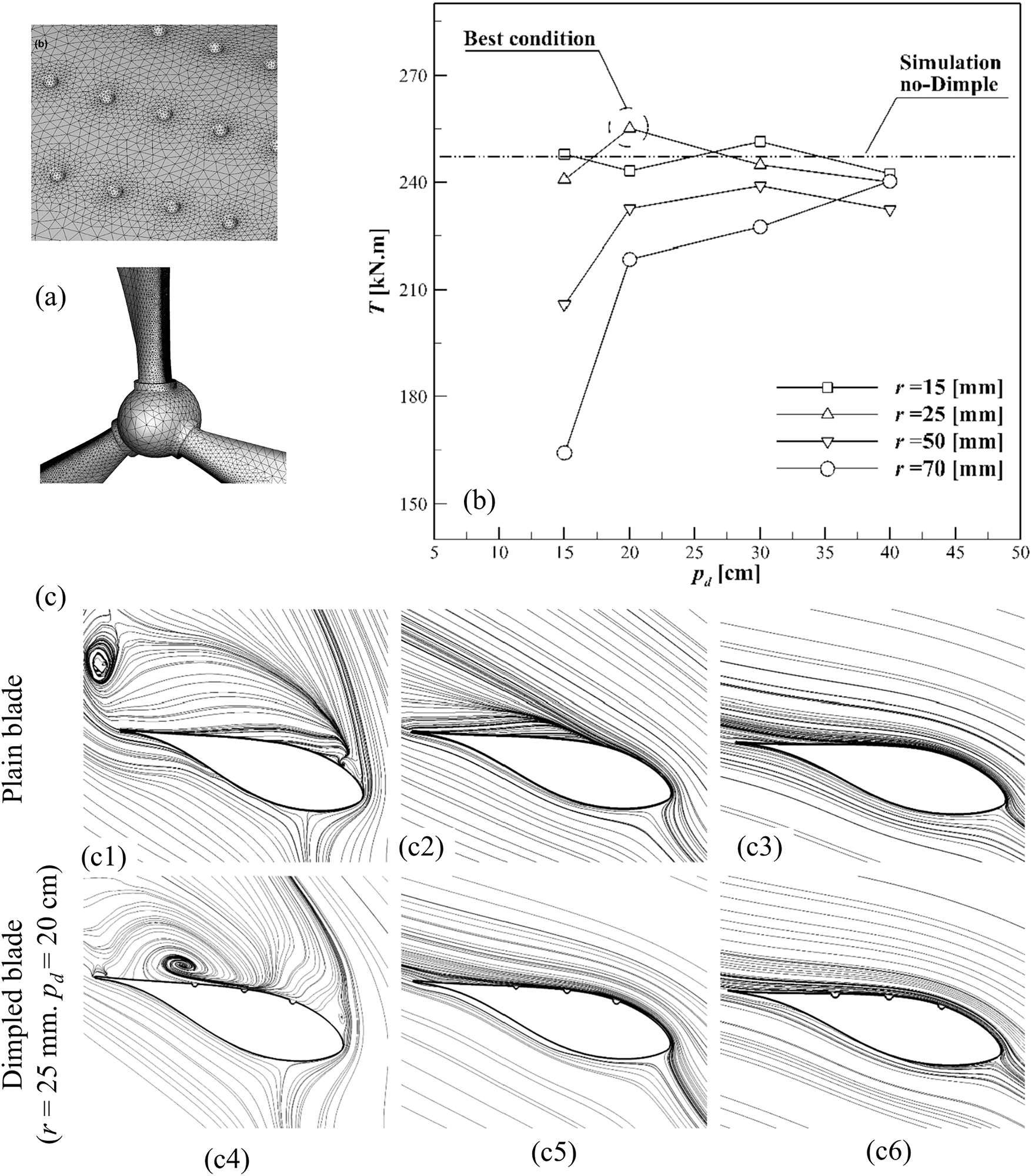
Figure 10: (a) Wind turbines and dimples on the suction surface of blades (V47-660 kW turbine). (b) Effects of dimple radius r and pitch distance p on torque generated on the turbine. (c) Streamline traces on sections at different radius Rb measured from the rotation axis: ((c1, c4)) α = 30.81°, Rb = 6.9 m (b) α = 27.02°, Rb = 7.5 m (c) α = 23.89°, Rb = 8.9 m for wind speed of 14 m/s and blade pitch angle Pa = 5°. Surface morphing. Adopted with permission from [14]. Copyright © 2020, Elsevier
Grooves: Grooves on the blade surface are indentations or channels that are designed into the aerodynamic profiles of blades, such as those on shark skin [15,81]. Rui et al. [41] found that the grooves and bulges on the surface of a pigeon wing are conducive to the increase in lift coefficient and the decrease in drag coefficient at a high angle of attack. In the study by Liu et al. [15], the effects of groove design on NACA4415 blades were investigated, utilizing both arc and rectangular grooves with varying dimensions and positions. The parameters included the depth-to-boundary layer thickness ratio h/δ = 0.5–2.0 and the groove depth-to-width ratio h/w = 0.10–0.15, with streamwise groove positions x/c = 0.10–0.22, where x is measured from the leading edge of the airfoil to trailing edge of the groove (Fig. 11). They found that rectangular grooves outperform arc grooves, with the optimum size (h/δ = 1.2; h/w = 0.10) at x/c = 0.16. The streamline patterns for groove types at this configuration revealed distinct behaviors in fluid flow (Fig. 11a–f). For h/δ = 0.5 (Fig. 11a,b), the fluid within the groove displays a recirculation pattern, with the center of recirculation located close to the downstream edge of the groove. When h/δ is increased to 1.2 (Fig. 11c,d), the recirculation becomes more pronounced, fully occupying the groove and improving the control over the boundary layer. For the large h/δ = 2.0 (Fig. 11e,f), a significant shift in the recirculation pattern is observed, moving upstream to the groove’s front edge for rectangular grooves, alongside the development of a secondary recirculation vortex near the downstream corners (Fig. 11f). The shift of primary recirculation center and the formation secondary vortex negatively impact the airfoil performance, making the groove size best at h/δ = 1.2.
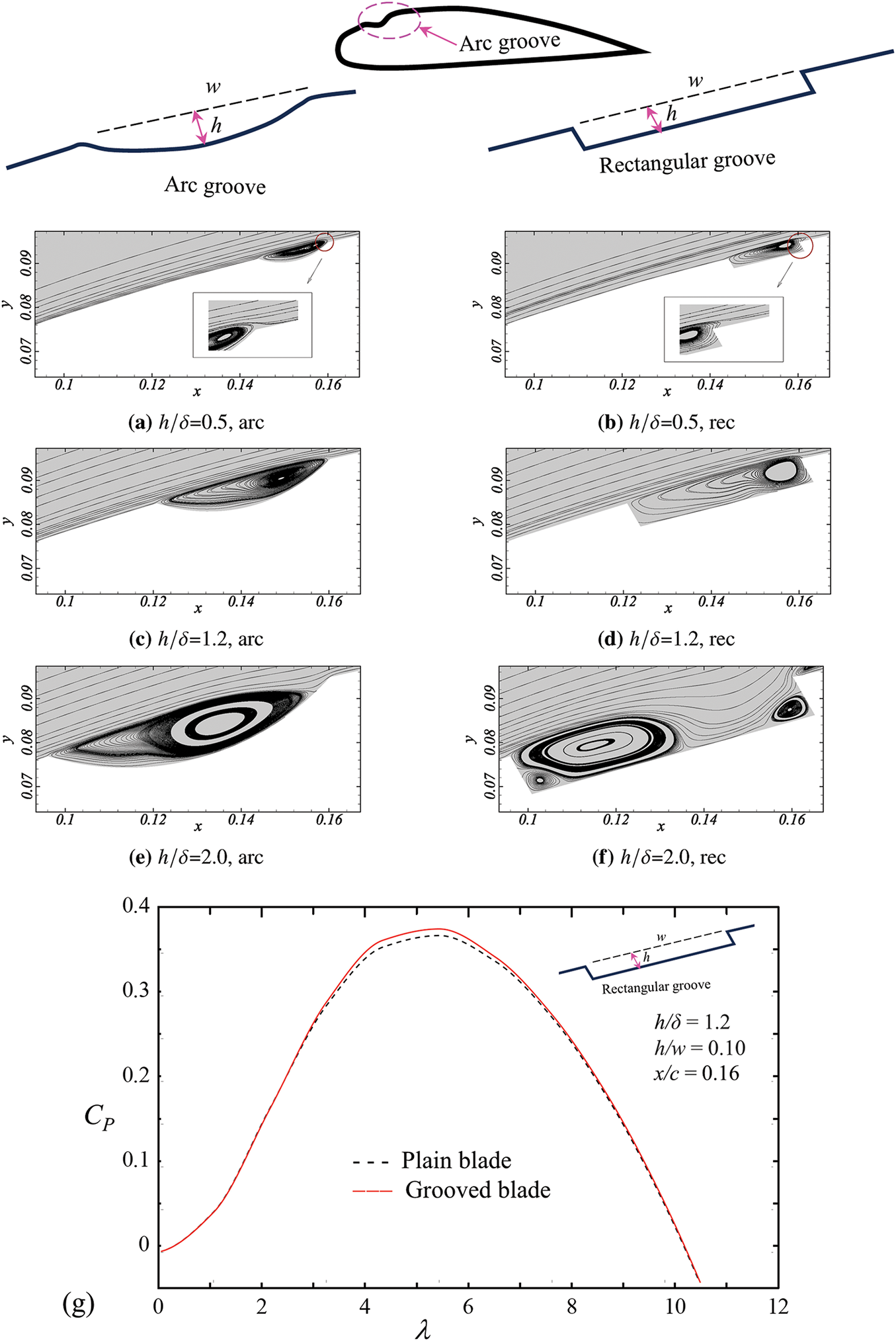
Figure 11: Streamlines over (a, c, e) arc grooves and (b, d, f) rectangular grooves with recess depths ratio h/δ = 0.5, 1.5 and 2.0 for groove aspect ratio h/w = 0.15, where δ is the baseline boundary layer thickness. (g) Dependence of power coefficient CP of the turbine with and without surface grooves on blade tip speed ratio λ. Grove position x/c = 0.16 on NACA4415 blade. Surface morphing. Adopted with permission from [15]. Copyright © 2020, Elsevier
The power coefficient CP predicted for small wind turbine displays that the maximum CP occurs at λ = 5.5 for both plain and grooved blades (Fig. 11g). The grooved blade turbine however demonstrates a more than 2% increase in CP compared to the plain blade turbine when λ = 4–6. At either lower or higher λ, the CP values for the grooved turbine closely align with those for the baseline. This suggests that grooves are particularly effective within this intermediate range of λ, enhancing the aerodynamic performance of the turbine in specific operating conditions.
Vortex generators: Vortex generators are aerodynamic devices installed on wind turbine blades to enhance their performance. They typically consist of small, fin-like structures strategically located along the blade’s surface [82,83]. These devices serve to delay or eliminate boundary layer separation, augment lift, reduce aerodynamic buffets, and minimize the afterbody drag of aircraft fuselages [84–88]. This function is particularly important at higher angles of attack, where the airflow can become turbulent and detach from the blade surface.
By increasing the effective lift generated by the blades, vortex generators enable the turbine to extract more energy from the wind, especially at low wind conditions. Their performance is optimized when their height is proportionate to the boundary layer thickness at the installation location [89]. Lin [90,91] discussed various types of vortex generators and their applications, noting their role in delaying boundary layer separation (Fig. 12). They referred to low-profile vortex generators as counter-rotating and co-rotating vane-type vortex generators as well as Wheeler’s doublet and wishbone vortex generators [92]. Lin [91] further demonstrated that vortex generators generating streamwise vortices—such as low-profile vortex generators, conventional vortex generators, and large longitudinal surface grooves—are the most effective. Research by Gao et al. [35] on a DU97-W-300 flat trailing blade found that while vortex generators significantly enhance lift, they may incur a drag penalty in the pre-stall region, which is mitigated in the post-stall region. Zhu et al. [93] applied vortex generators to the S809 blade and found a delay in the onset of dynamic stall, resulting in an approximate 40% increase in the maximum lift coefficient.
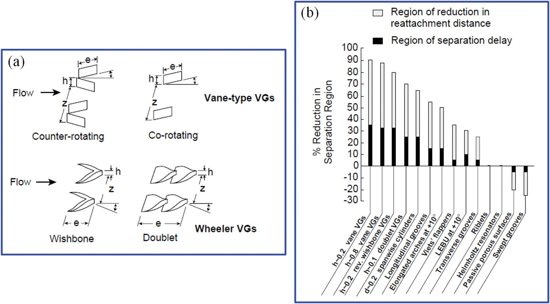
Figure 12: (a) Different types of vortex generators. (b) Relative effectiveness in flow separation delay for various vortex generators. Surface morphing. Adopted with permission from [91]. Copyright © 2002, Elsevier
Jets: Jets created through small slots or holes are used to blow or suck air on the turbine blade surface to improve the power coefficient. Akhter et al. [94] demonstrated that these methods are among the most popular active flow control methods for turbine blades. In addition to delaying transition and reducing drag, jets effectively suppress flow separation and increase blade lift by altering the momentum balance of the boundary layer. Cheeseman et al. [95] and McLachlan [96] investigated the effects of tangential blowing jets on the suction surface of the blade, focusing on their impact on flow circulation and lift enhancement [97]. However, effective tangential blowing requires a blunt or rounded trailing edge [98]. Many experimental and numerical studies used suction jets on airfoils. Karim et al. [99] and Alfrefai et al. [100] found that a leading-edge suction jet on a pitching blade can effectively suppress flow separation, postpone dynamic stall, and increase the lift-to-drag ratio [101]. Furthermore, combining blowing and suction is more effective than using either method standalone [102,103]. These jets can utilize the same or different holes for airflow. For example, Chng et al. [102] applied tangential blowing near the leading edge and suction near the trailing edge. Zha et al. [104,105] demonstrated that this technique can increase peak lift by 113%–220% and 100%–153%, respectively.
Wang et al. [76] examined the impact of blowing and suction on the lift-to-drag ratio, cut-in speed, flow separation, and flow reattachment to identify optimal control conditions. They found that a blowing jet positioned at 0.2c from the leading edge is the most effective in increasing the lift-to-drag ratio by 804% and reducing the cut-in speed by 15.38% (Fig. 13a,b). The blowing enables the formation of a laminar separation bubble even at α = 14° which represents a post-stall condition for the baseline blade without blowing (Fig. 13e,f). This results in not only enhanced lift but also reduced drag (Fig. 13a), explaining why the lift-to-drag ratio is very high for this case. On the other hand, when both blowing and suction are applied (Fig. 13c), the drag reduction is not as significant as that for single blowing, which restricts the enhancement of the lift-to-drag ratio (Fig. 13d). In this scenario, two separation bubbles are formed: a laminar separation bubble, and a turbulent separation bubble (Fig. 13g,h). The latter appears between the blowing and suction jets.
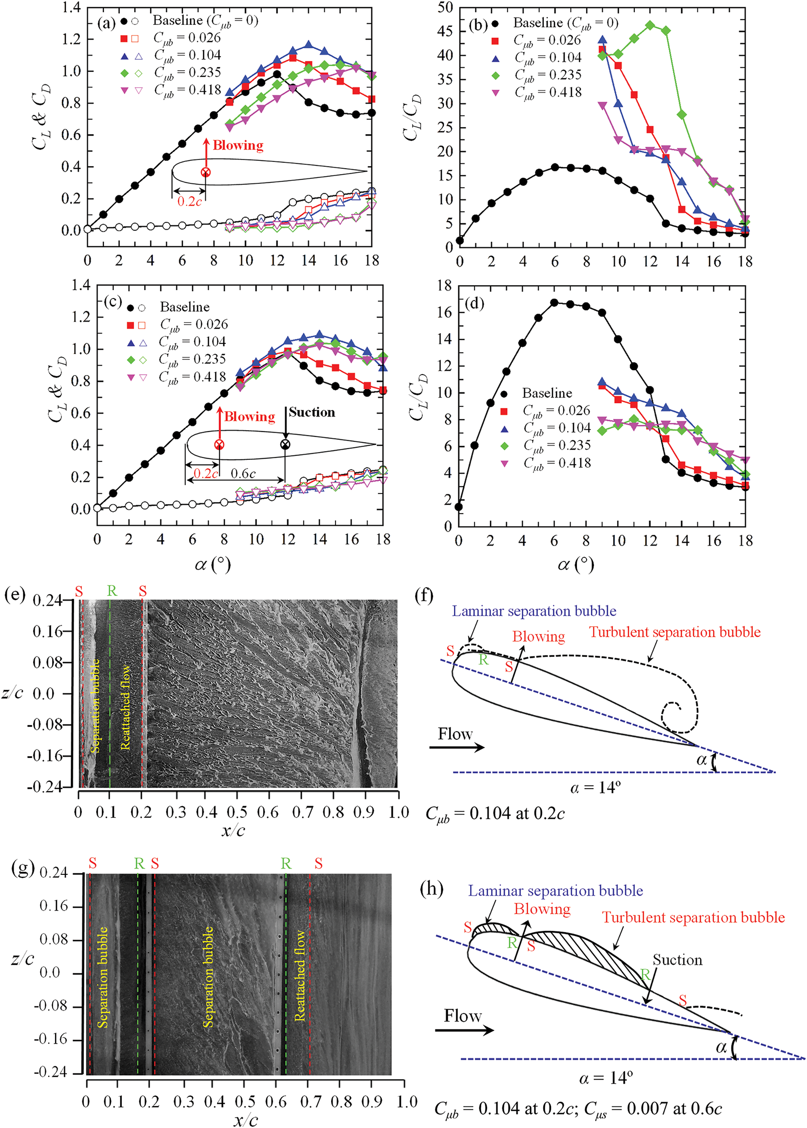
Figure 13: Dependence of lift CL, drag CD and CL/CD of airfoil on momentum coefficient Cμb of blowing jet at 0.2c (a, b) with blowing jet only, and (c, d) with the suction jet Cμs = 0.007 at 0.6c. (e–h) Surface oil flow visualizations and flow sketches on the suction surface of the airfoil at α = 14°: (e, f) with blowing jet only, and (g, h) with both blowing and suction jets. Surface morphing. Adopted with permission from [76]. Copyright © 2022, Elsevier
Feathers: The self-activating feathers on birds’ wings enhance flight efficiency, providing a high lift-to-drag ratio and improving maneuverability for landing and prey capture. This natural mechanism has inspired biomimetic control methods for airfoil flow management [106–109]. Mimicking feather movements to delay stall and enhance lift by controlling flow separation and modifying vortices is gaining traction due to its passive, self-adaptive nature. Schatz et al. [110] found that self-deploying flaps on the HQ17 airfoil increased lift by over 10% at stall angles by blocking reverse flow and delaying separation. Bechert et al. [111] and Meyer et al. [112] in wind tunnel experiments confirmed that adaptive flaps significantly improve aerodynamic performance and prevent flow separation as the angle of attack increases. Schluter [113] demonstrated that an adaptive flap on the SD8020 airfoil achieved about a 50% increase in lift at a post-stall angle of 15° under optimal conditions. Wang et al. [114] studied the use of real feather flaps on both the suction and pressure sides of a NACA0012 airfoil and highlighted the significant impact of these flaps on the aerodynamic performance (Fig. 14a,b). The flap on the suction side is beneficial only at large attack angles, particularly beyond the stall (Fig. 14c). In contrast, when the same is added on the pressure side, the flap enhances lift by 186% and the lift-to-drag ratio by 72% at small α = −4° to 8° (Fig. 14d). Time-averaged measurements revealed that vorticity around the flapped airfoil weakened, streamwise velocity decreased, and lateral velocity increased compared to the plain airfoil, which contributed to the improved lift-to-drag ratio.
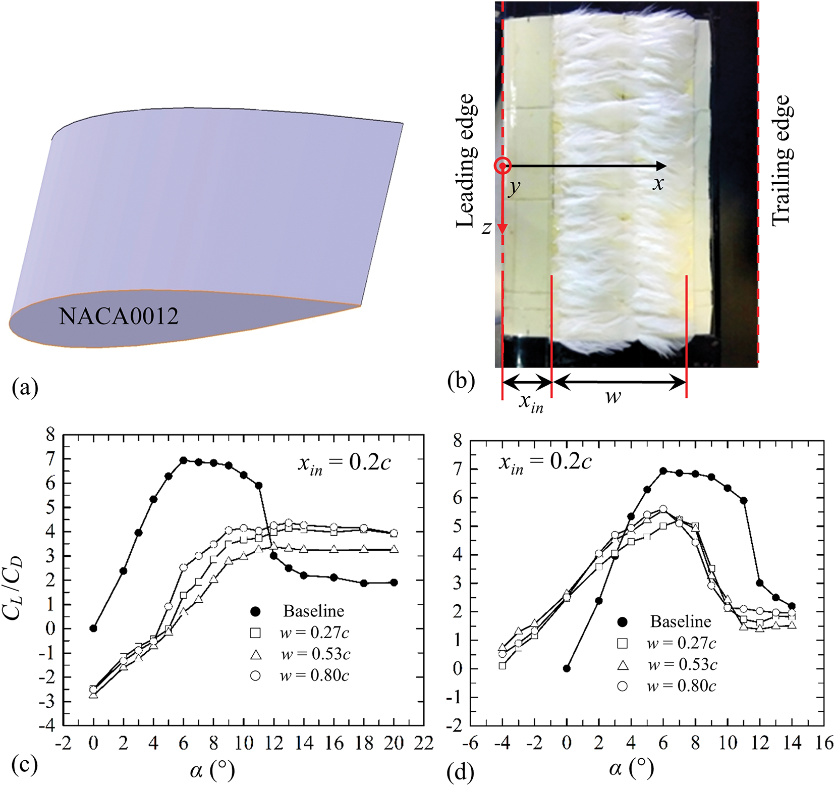
Figure 14: (a) Airfoil model NACA0012 (b) Single array of feather flaps made from Chinese spot pigeon with width ratio w/c = 0.27. Dependence of CL/CD on flap width w and its position xin when the feather lap is on (c) suction surface, and (d) pressure surface. Surface morphing. Adopted with permission from [114]. Copyright © 2019, IOP Publishing Ltd.
3.1 Blade Elasticity and Fluid-Structure Interactions
A wind turbine blade features a complex aerodynamic profile, being wider at the base and thinner at the tip, shaped like an airfoil to generate lift and counteract drag. The blade also has a twisted pitch, which is angled 10°–15° steeper at the base. As the size of wind turbine blades increases, their flexibility also rises. Due to their longer aspect ratio, turbine blades are generally more elastic and can undergo vibrations arising from fluid-structure interactions [115,116]. With blade lengths projected to reach 151 m in 2035 (Fig. 3b), their elasticity will further increase. Currently, megawatt-class wind turbines dominate the wind power market, with blades becoming longer and lighter (Fig. 15). As wind power generation rapidly evolves, ensuring the wind turbines’ safe and reliable operation is paramount. The blades are critical components, and their performance directly impacts the reliability of the entire generator system (Fig. 16). In the event of a blade failure, even the breakage of a single blade can disrupt the balanced rotation of the three blades, leading to violent vibrations and potential collapse of the turbine structure. Bladena’s online seminar, “CORTIR Blade Failure Seminar”, held on 26 November 2020, brought together representatives from 27 wind turbine owner companies and CORTIR partners. The seminar highlighted a concerning trend: an increase in blade failures with increasing blade size; the issue of blade failures is more critical than ever (Fig. 15).
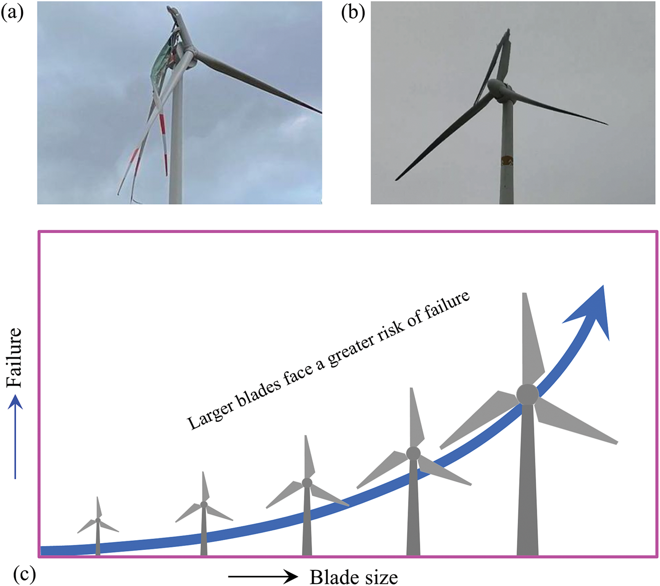
Figure 15: Blade failure incidents and prediction. (a) The blades of an Enercon E-138 EP3 4.2 MW wind turbine in Nattheim wind farm in Southern Germany were seriously damaged due to the storm (Foto: Stadtwerke Heidenheim). (b) The blade of a wind turbine in Liaoning was broken when the wind speed was about 7 m/s (https://wind.in-en.com/html/wind-2430552.shtml (accessed on 1 January 2025)). (c) Failure rate of blades against blade size (Bladena news 27/11/2021). Flow-induced vibrations
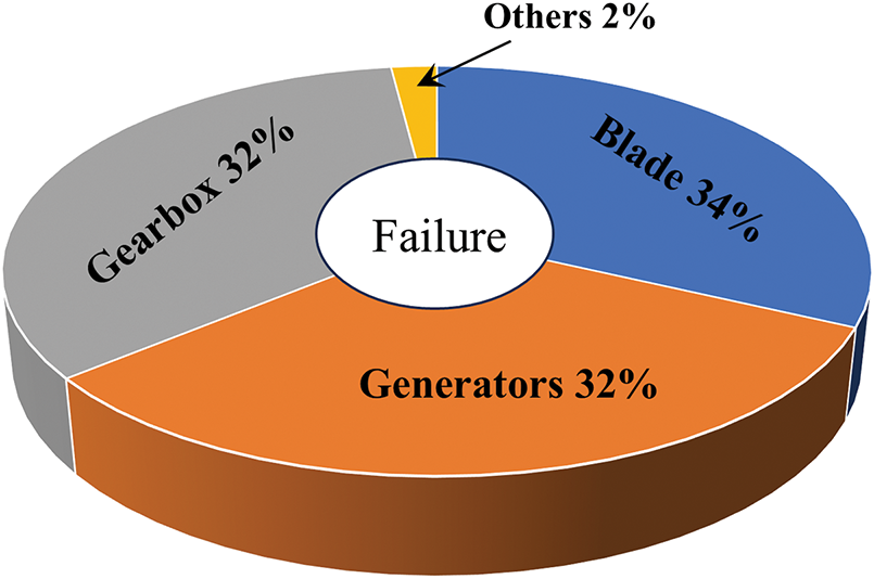
Figure 16: Failure rates of wind turbine components. Adopted with permission from [117]. Copyright © 2015, Elsevier
Fluid-structure interactions play the main role in violent vibrations, potentially leading to damage or failure of wind turbine blades. Blade vibration is a critical factor that impacts wind turbine performance, efficiency, and lifespan. Therefore, understanding and managing these vibrations is essential for optimizing turbine design, ensuring structural integrity, and improving energy production. Wind turbine blades exhibit considerable randomness in their responses to wind-induced forces and moments [117,118]. Depending on the wind speed and angle of attack, the wind flow over the blade may generate large-scale vortex structures, causing significant unsteady flow separation. This flow separation results in dramatic fluctuations in the blade’s pitching, heaving, and bending responses as well as affecting its frequency response [119]. Historically, research has focused primarily on flow separation, wake structures, and the forces acting on a fixed airfoil. However, there has been relatively little attention given to aerodynamic instabilities, especially regarding the vibration and frequency response of cantilevered airfoil models that replicate turbine blades.
Flow-induced vibration is a critical phenomenon not only in the wind turbine industry but also across various engineering applications, including heat exchanger tubes, ocean risers, and aircraft wings. For bluff bodies, this kind of vibration typically manifests in two primary forms: vortex-induced vibration and galloping. Vortex-induced vibration occurs when the frequency of the vortex shedding from the bluff body coincides with the natural frequency or oscillation frequency of the body. This resonance effect can lead to significant oscillations over a specific range of reduced flow velocities, a phenomenon known as ‘lock-in’ [120–122]. During this state, the amplitude of the vibrations can become substantial, potentially leading to structural concerns. In contrast, galloping is characterized by large-amplitude, low-frequency self-excited oscillations that occur in non-circular structures or multiple structures when the flow speed exceeds a critical reduced velocity [123–127]. Unlike vortex-induced vibration, galloping is associated with aerodynamic instabilities that arise from the changes in the aerodynamic forces acting on the structure rather than simply resonating with the shedding vortices [128–134].
However, flow-induced vibrations of streamlined structures, such as wind turbine blades, differ significantly from those of bluff bodies. Wind turbine blades can exhibit three degrees of freedom (3-DOF) in their structural responses: pitching (torsional vibration), heaving (transverse vibration), and bending (streamwise vibration). The aerodynamic forces acting on a blade include lift, drag, and moment, all of which are influenced by various factors, including the angle of attack, Reynolds number, reduced velocity, mass ratio, rotational inertia, and pivot location. During the blade rotation, this large-diameter blade is very susceptible to vibrations in the swing direction, in addition to bending and torsional deformations due to wind-induced instability and inertial forces/moments of the blades. When the bending, heaving, and pitching motions are coupled with each other, a very strong classical flutter is easily formed. Such flutter is often rapid and destructive and must be avoided in the design and operation of wind turbines.
The interaction between a blade and wind flow creates a pressure fluctuation on the foil surfaces. During the interaction, the surface pressure generates forces and drives the blade to vibrate. The vibration induces vortices and creates a lock-in state. If the vortex shedding frequency is close to the natural frequency of the blade, the vibration amplitude of the structure increases significantly and affects the vortex shedding mode [120,135]. Kato et al. [136] observed a similar coupling or lock-in between the controlled pitching frequency of a blade and the cavity breakdown frequency. Besem et al. [137] found that the blade vibration amplitude in the case of lock-in was four times higher than that in the case of non-lock-in. Controlling the wind-induced vibration is crucial to minimize the risks of a wind turbine blade failure, and one way to do so is by predicting vibration frequency for lock-in, which is reliably obtained from a foil response analysis. Meskell and Pellegrino [138] made a lock-in map for different angles of attack and frequency ratios, suggesting that periodic vortex shedding appears at 35° ≤ α ≤ 145°. For the vibration amplitude considered, the risk of vortex-induced vibration is more significant at α ≈ 40° and α ≈ 140°. Benner et al. [139] experimentally investigated the vortex-induced vibration response of a blade vibrating in the crossflow direction only in the range of 0° < α < 180°, over a range of reduced velocities Ur = 0.6–13.0 and a range of Reynolds numbers Re = 600–13,300 (Fig. 17a). Vibrations are observed for angles of attack in the range of α = 60°–130° over a range of reduced velocities for each angle of attack. The α = 90° case exhibits the widest lock-in range (1.7 < Ur < 12) and the largest peak amplitude (A* = 1.93 at Ur = 5.7). The lock-in is confirmed by airfoil oscillation frequency fo measurements in Fig. 17b. The oscillation frequency ratio f* (=fo/fnw) remains approximately 1.0 for Ur < 6 before gradually increasing with increasing Ur > 6. The increase is attributed to decreased flow-induced added mass [122,140,141]. The natural frequency fnw in still water is itself dependent on α (Fig. 17c), reaching a maximum at α = 90° [142].
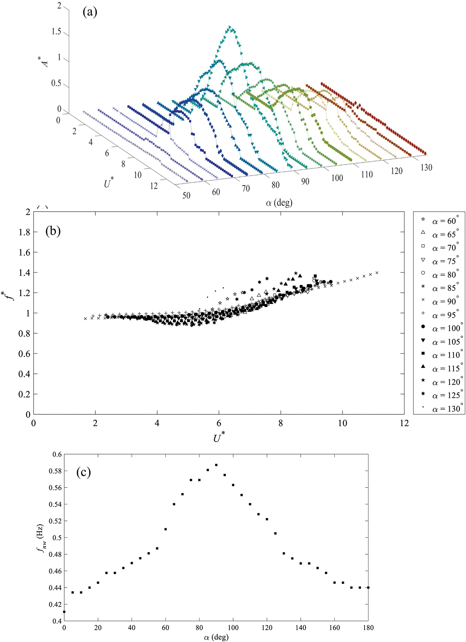
Figure 17: Variations with reduced velocity Ur and α (=55°–135°) of (a) vibration amplitude A*, and (b) vibration frequency ratio f* (=fo/fnw). (c) Dependence of natural frequency (fnw) of the airfoil in still water on angle of attack (α) in the range of 0° ≤ α ≤ 180°. Flow-induced vibration. Adopted with permission from [139]. Copyright © 2021, Elsevier
Shin et al. [143] for two-dimensional foil investigated the effects of bending stiffness of the foil on the thrust acting on the heaving foil. The increased flexibility of the foil results in higher thrust and decreased vertical force. Ducoin et al. [144] investigated the tip heaving and twisting deformations of a cantilevered hydrofoil with a 2-DOF solver at Rec = 0.75 × 10⁶ – 3 × 10⁶ and α = 2° – 8°. Ananth et al. [145] indicated that with the increase of blade camber, the lift force experienced by the blade in the heaving direction increases. This makes the blade more prone to bending flutter. When the ratio of the torsional and bending frequencies approaches unity, the flutter velocity increases in the torsional mode, and coupled bending–torsion flutter occurs. When a blade with a significant difference in bending and torsional stiffness is employed for operation, torsional flutter occurs only at higher air velocities, and at lower air velocities, the structure is prone to bending flutter.
Tang et al. [146] investigated theoretically and experimentally the limit-cycle oscillations of a high AR wing and found that the effect of structural nonlinearity was determined by the ratio of the flap and chordwise bending stiffnesses. Tang et al. [147] found that a gusty wind produced a significant effect on structural responses. Meng et al.’s [148] experimental and theoretical analyses on the flutter boundary and gust response of a flexible wing revealed that the chordwise bending mode coupled with the torsion mode could decrease flutter speed greatly.
Aerodynamic noise from wind turbine blades is the sound generated by the interaction of wind with the blades during operation. This phenomenon plays a significant role in the overall noise profile of wind turbines and can impact the operation and performance of the turbines as well as their acceptance by nearby communities [149,150].
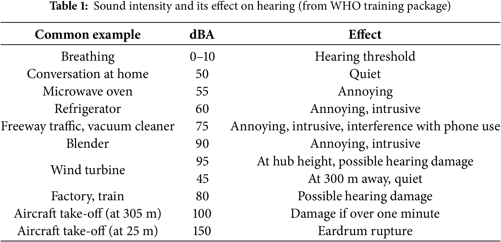
Blade noise from wind turbines poses a significant issue for nearby aquatic animals (offshore turbines), wildlife, and residents, especially pregnant women, babies in wombs, and newborns. Over time, children living nearby may be at risk of hearing loss and diminished academic performance. Therefore, it is essential to understand the mechanisms behind this noise generation and explore effective strategies for noise reduction. Mitigating the noise issues associated with wind turbines remains a challenge. When operating at full capacity, a wind turbine can produce noise levels of up to 95 dBA at its base, which is higher than that generated by household appliances like blenders and vacuum cleaners (Fig. 18). This noise level poses a risk of hearing damage, particularly at the turbine’s base (Table 1). As the distance from the turbine increases, the noise level diminishes, reaching an acceptable level of 45 dBA at approximately 300 m. Consequently, wind farms are typically located at least 300 m away from residential areas to minimize the impact on nearby communities.
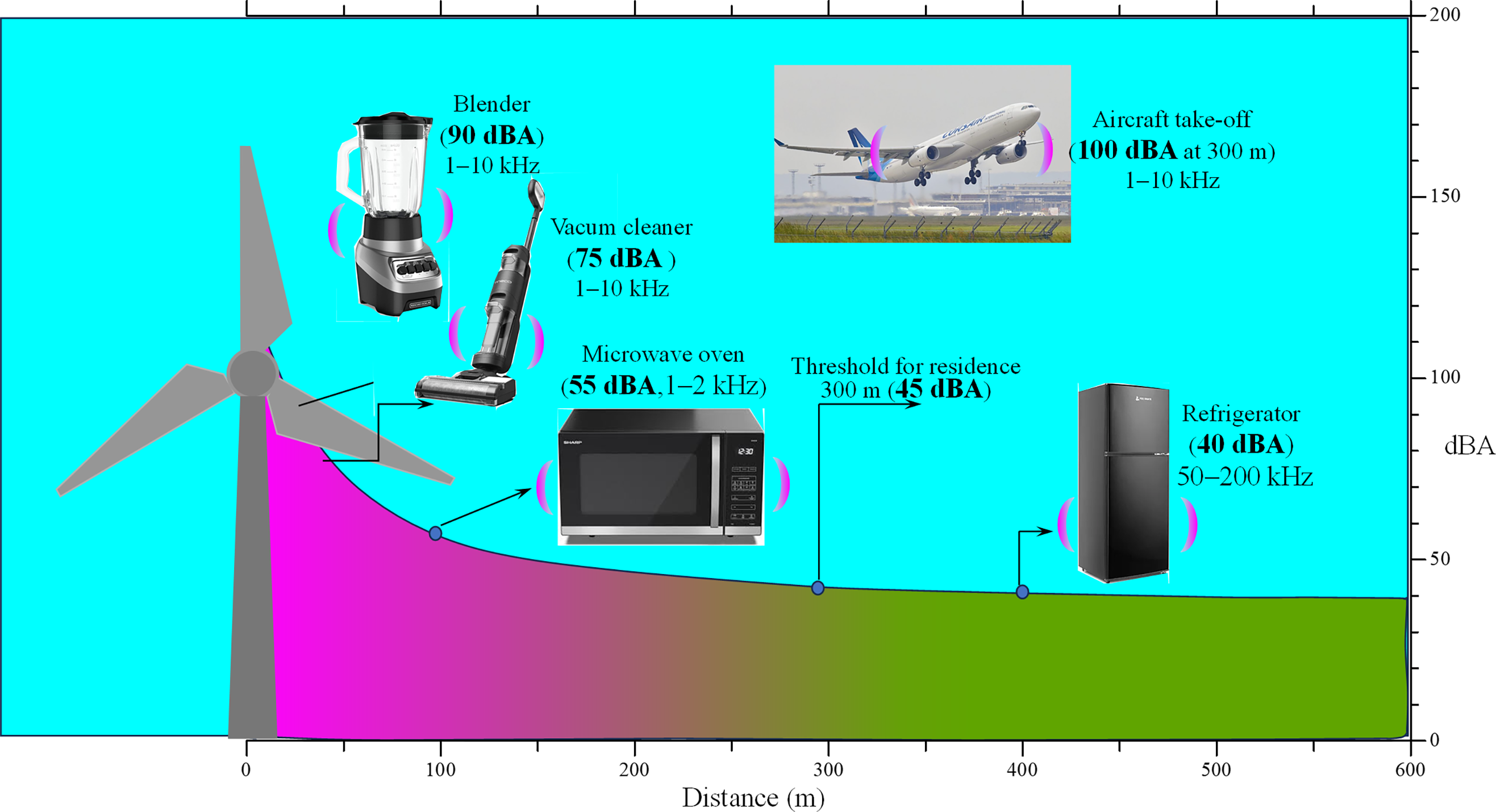
Figure 18: Wind turbine noise variation with distance and its comparison with other that from other appliances
Wind turbine noise exhibits distinct characteristics—periodicity, amplitude modulation, and pronounced low-frequency components—that make it uniquely annoying to listeners [151]. Pedersen and Waye [152], in their study on noise perception and annoyance, demonstrated that wind turbine noise tends to cause a higher proportion of annoyance among individuals compared to other community noise sources at equivalent A-weighted sound pressure levels (Fig. 19). Notably, the proportion of individuals reporting annoyance increased as a third-order polynomial function with rising sound pressure levels. While transportation noise annoyance primarily stems from indoor sound exposure, where facade attenuation may reduce actual noise levels, wind turbine annoyance is mainly experienced during outdoor activities, where the noise has amplitude modulation and is not masked by ambient noise. This issue of annoyance is particularly pronounced in rural landscapes, where the quiet surroundings amplify the perceptibility and impact of turbine noise. In contrast, urban environments, with their higher baseline noise levels, appear to mitigate the relative impact of wind turbine noise. However, in rural areas, wind turbine noise has been associated with significant adverse effects, including sleep disturbances and disruptions to psycho-physiological restoration, further exacerbating its impact on well-being [153,154].
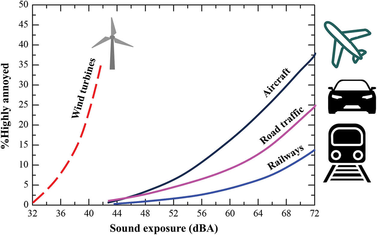
Figure 19: Comparison of annoyance by wind turbine noise and transportation noise. Reproduced from [152]. Adopted with permission from [152]. Copyright © 2004, Acoustic Society of America
The mechanisms of wind turbine blade noise primarily stem from the interaction of the blades with the airflow [155]. This interaction generates noise through five main processes: leading-edge vortex interaction, trailing-edge vortex, tip vortex, turbulence buffeting, and blade vibration (Fig. 20). Leading-edge noise occurs when airflow interacts with the front edge of a blade, often involving the creation of separation bubbles and vortices. When the airflow separates from the leading edge, it can generate large-scale vortices that contribute significantly to the overall noise produced by the turbine. Trailing-edge noise is generated by the interaction of the boundary layer turbulence with the trailing edge, which is the primary noise source of turbine blades. In addition, as air flows over the blades, the trailing edge creates small- and large-scale vortices in the wake, making the wake highly turbulent. These vortices and turbulence generate sound, often described as a whooshing or rushing noise. Turbulence buffet noise arises from the interaction of wind turbine blades with turbulent airflow. This interaction scatters vorticity once the flow impacts the leading edge, producing sound and causing rapid pressure fluctuations. Tip vortex noise results from the vortices generated by the tips of the blades. Blade vibration noise springs from the oscillations and vibrations of wind turbine blades during operation, which significantly impact turbine performance and the acoustic environment around wind farms.
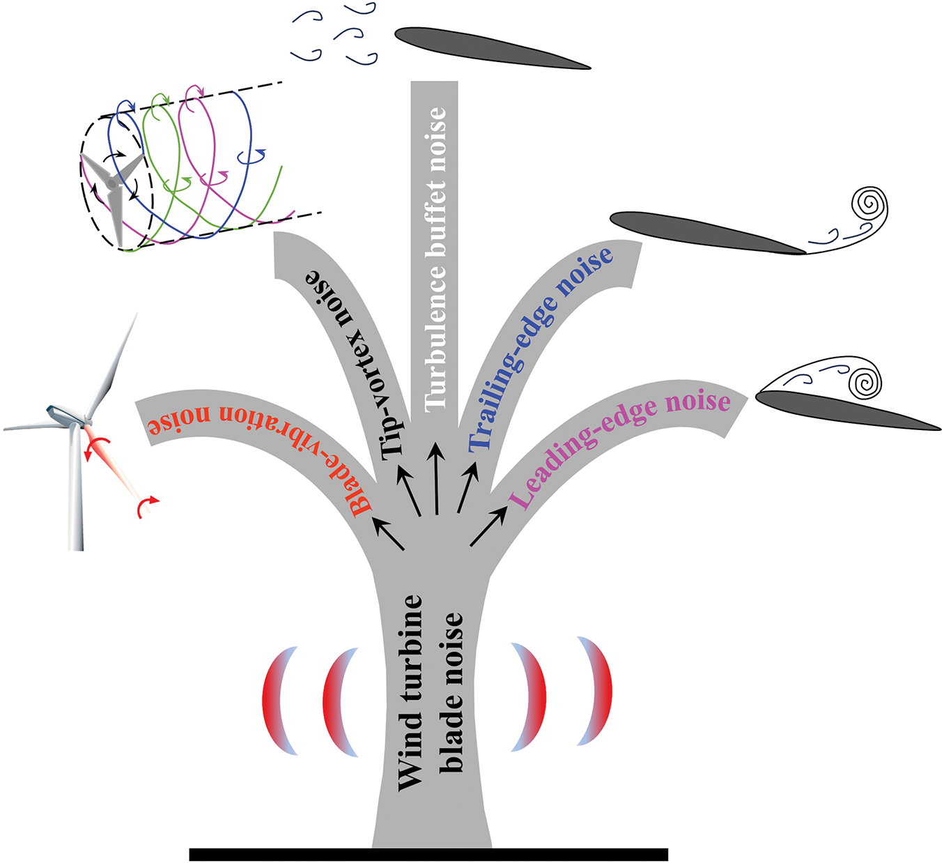
Figure 20: Blade noise tree: major classification of aerodynamic noise of wind turbine blade
Over the last decade, modifications to the airfoil geometry have been made as a passive treatment to reduce turbine noise. The results indicated that alterations to leading-edge geometries—including changes in thickness, camber, or nose radius—do not significantly mitigate noise levels [156]. Karthikeyan et al. [157] however showed that a thin, curved trailing edge may enhance efficiency and decrease noise level. Among various noise-reduction techniques, incorporating serrations or undulations on the leading edge of the blade shows considerable promise. Chaitanya [156] established that, for optimal effectiveness, the wavelength of the serrations should be four times the turbulence integral length scale. The effectiveness of serrations in attenuating noise is not only contingent on their geometric characteristics but also intricately linked to the turbulent flow dynamics surrounding the airfoil. By adhering to the established wavelength criteria, the potential for sound power reduction can be maximized, paving the way for more efficient and quieter aerodynamic designs.
Most existing research on leading-edge serrations has primarily focused on sinusoidal and sawtooth profiles, using theoretical analysis [158–160], numerical simulations [161–165], and experiments [78,102,156,166]. Each approach has contributed to our understanding of how serrated edges can influence noise generation, yet there remains a need for broader investigations that assess diverse profiles and configurations to fully realize their acoustic benefits.
There are three main approaches to studying noise reduction (Fig. 21): (i) designing new low-noise airfoils that maintain aerodynamic performance unchanged [167,168], (ii) applying flow control for both noise reduction and aerodynamic performance enhancement [169–171], and (iii) applying flow control for noise reduction with some aerodynamic performance degradation [172,173].
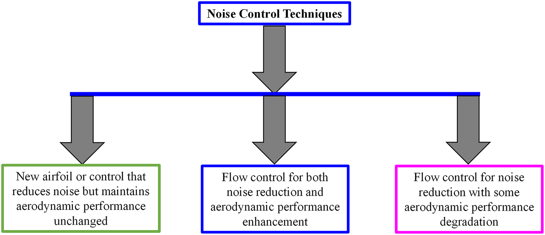
Figure 21: Noise controls and their outcomes
Rodrigues et al. [169] reported that increasing the blade surface roughness improved output power by 8.7% and reduced aerodynamic noise by 3.5 dB. Similarly, Benim et al. [170] found that optimizing the shape of the S822 airfoil increased power output by 8% and decreased noise levels by 6.6 dB. Sanaye et al. [171] achieved a 26% increase in the lift-to-drag ratio of blades, along with a reduction in aerodynamic noise by 1.11 dB.
Ma et al. [174] examined the effectiveness of airfoil concavity on the suction surface to reduce noise and found that power is increased by 3%–15% and noise drops by 9.6%–15.8%. There are some studies on the multi-element coupling design, which combines two or more elements to alleviate noise. Chen et al. [175] studied the sound suppression mechanism of the long-eared owl using a stereo microscope, scanning electron microscopy, and laser scanning confocal microscope. The result shows that the leading-edge serration, the trailing-edge fringe, and the multi-layer grid porous structure all affect sound absorption. Wang et al. [176] designed a bionic coupling airfoil with wavy leading-edge, trailing-edge serrations, and surface ridges to reduce the noise of an airfoil. Wang et al. [77] designed a bionic coupling airfoil with a cross-section of the long-eared owl’s wing, wavy leading-edge, and serrated trailing edge. Compared with the bionic airfoil, the average sound pressure level of the bionic coupling airfoil is reduced by 9.94 dB, and the lift-to-drag drag ratio is increased.
4.4 Turbine Tower Noise and Control
The wind flow around the tower can create additional noise when the blades pass through the disturbed air [177]. Turbine tower noise and its control represent significant aspects of wind turbine engineering and environmental management. The noise primarily originates from blade-tower interactions, and mechanical vibrations within the turbine system [178]. These vibrations can travel through the tower structure, with the steel tower sometimes acting as an amplifier, creating both audible noise and low-frequency resonance. Yu et al. [179] investigated how blade-tower interaction affects unsteady flow and noise generation in the near wake of a wind turbine tower through wind tunnel experiments. Their findings showed that blade passing creates irregular velocity patterns and affects vortex behavior in the tower’s near wake, with the most notable impact seen in Reynolds shear stress variations. The study concluded that aerodynamic noise behind the tower primarily results from increased momentum exchange caused by fluid ejection and bursting events, which are driven by Reynolds shear stress. This momentum exchange leads to higher turbulent kinetic energy, resulting in fluctuations in fluid velocity and pressure that generate noise. The research suggests that reducing fluid mixing and pressure fluctuations could effectively decrease tower-generated noise.
The control of tower noise involves multiple approaches. Structural modifications form the first line of defense, incorporating vibration-damping materials and reinforcement elements to reduce noise transmission. Isolation techniques, such as elastomeric bearings and spring isolators, help separate vibrating components from the main structure. Advanced active control systems employ smart damping and real-time monitoring to adaptively respond to changing noise conditions. The implementation of these control strategies requires a comprehensive approach, combining multiple methods to achieve optimal results. Regular monitoring and assessment help maintain system effectiveness, while documentation and periodic evaluations ensure compliance with noise regulations and community standards. This systematic approach to noise control helps maintain operational efficiency while minimizing environmental impact.
These measures are essential not only for meeting regulatory requirements but also for ensuring long-term operational sustainability and community acceptance of wind turbine installations. Successful noise control contributes to both the technical performance of the turbine and its social acceptance in surrounding communities.
5 Integrated Wind Turbine Development
The successful development of modern wind turbine systems hinges on several key facts and crucial analyses across various disciplines, relying on structural dynamics, aerodynamics, power conversion, grid integration, blade design, material selection, blade durability, manufacturing process, and cost, environmental impact, and economy and policy framework. The coordination and integration of these approaches are presented in Fig. 22. Rašuo et al. [180] comprehensively reviewed the harmonization of the new wind turbine rotor blades development process. Predicting blade fatigue life and mitigating vibrations requires detailed analysis of wake dynamics, structural responses to various loading conditions (including wind gusts and centrifugal forces), and aeroelastic interactions between the blade and airflow. This analysis informs the optimization of material selection, blade geometry, and vibration control systems. Particularly, analyzing the wake generated by the turbine blades is crucial for optimizing farm layouts and minimizing power losses due to wake interference. This involves sophisticated numerical simulations and experimental measurements to understand wake meandering and recovery. Analysis of airfoil performance across a wide range of operating conditions (including yaw, shear, and turbulence) is crucial. The impact of leading-edge erosion and surface roughness on performance also needs thorough investigation. Efficient power conversion systems, incorporating advanced power electronics, are crucial for maximizing energy capture and ensuring stable grid integration. This requires careful analysis of grid-forming and grid-following capabilities, as well as robust fault-ride-through performance. Furthermore, the impact of variable renewable energy sources, such as wind power, on overall grid stability must be thoroughly considered.
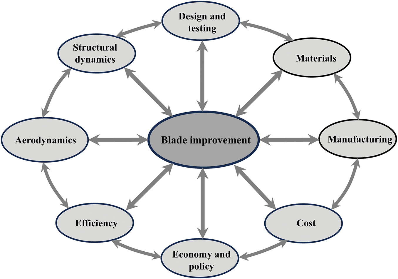
Figure 22: Integrated approach to new wind turbine blade development
High-performance composites, with their high strength-to-weight ratio, excellent fatigue, and corrosion resistance, are well-suited for wind energy. While their increasing use in critical wind energy structures offers significant advantages, challenges remain. These include the need for entirely new design, fabrication, and qualification processes; difficulties in analyzing internal stresses and demonstrating compliance to certifying agencies; establishing appropriate test criteria; and accurately quantifying environmental degradation. Material selection for blades, towers, and other components prioritizes fatigue and corrosion resistance while maintaining cost-effectiveness to ensure long-term durability and minimize maintenance. Optimizing manufacturing processes, including the exploration of advanced techniques like additive manufacturing and composite material processing, is crucial for reducing production costs and enhancing quality control. Finally, a thorough environmental impact assessment, encompassing noise pollution, avian and bat mortality, and visual impacts, is essential, alongside the development and evaluation of effective mitigation strategies. Comprehensive lifecycle cost analysis is necessary for evaluating the economic viability of wind energy projects. Supportive policies and regulations are equally essential for stimulating investment and ensuring the safe and efficient operation of wind farms.
Optimizing wind farm layout significantly impacts energy production and efficiency. Studies have shown that careful placement of turbines can lead to substantial increases in overall power output, considering factors like wind resource characteristics, terrain, wind direction, energy distribution, turbine wake interactions, and construction feasibility. Optimizing wind farm design presents a multidisciplinary engineering challenge encompassing wind turbine selection, wind farm rating, layout determination, and energy production analysis. While some researchers, such as Aytun Ozturk et al. [181], employed greedy heuristic methods to maximize profit, others [182–184] utilized genetic algorithms to minimize the cost per unit energy, adhering to constraints such as minimum turbine separation and farm boundaries. Donovan [185] and Yeghikian et al. [186] focused on maximizing power output subject to constraints on turbine number, proximity, and interference. These studies generally placed turbines at the center of grid cells, not optimizing precise positioning. In contrast, Rasuo et al. [187] employed a real-coded genetic algorithm to optimize turbine placement freely, thereby minimizing wake effects and achieving continuous position adjustment. Research consistently demonstrates that optimized wind farm layouts, achieved through advanced modeling and simulation, offer significant improvements in energy yield and efficiency compared to simpler, less sophisticated approaches.
This paper reviews the progress of research done on multiple interconnected aspects such as aerodynamics influencing the power coefficient, aeroelasticity affecting vibration, and aero-acoustics addressing noise generation, offering more effective and sustainable wind energy solutions and advocating for a more holistic approach to the design and development of wind turbine blades. The exploration of various aerodynamic designs, including the use of grooves and leading-edge serrations, demonstrates significant enhancements in the performance of wind turbine blades. Studies indicate that specific design parameters, such as groove size and shape, can improve lift-to-drag ratios and optimize airflow above the blades, ultimately leading to increased power coefficients.
The incorporation of blade morphing techniques, inspired by biomimetic approaches, shows promise in enhancing turbine efficiency. Innovations that reflect the geometry of natural systems, such as owl wings, have been successful in improving power coefficients compared to traditional blade designs. This suggests that further exploration of biomimetic designs could lead to substantial advancements in turbine efficiency and performance.
With the rapid evolution of wind power generation, turbine blade sizes are rapidly increasing. The blades are becoming more elastic and are thus more susceptible to violent vibrations caused by fluid-structure interactions. Ensuring the safe and reliable functioning of wind turbines has become essential. Understanding fluid-structure interactions is essential for the lifespan, performance, and safety of wind turbine blades, which impacts both operational efficiency and the safety of nearby residents. The findings emphasize the critical role of blade elasticity and fluid-structure interactions in the performance and longevity of wind turbines. As turbine blades increase in size, their tendency to vibrate poses a significant risk to operational stability. Understanding how to manage these vibrations is essential for optimizing turbine performance and mitigating risks.
The interaction between blades and airflow generates noise through five main processes: leading-edge vortex interaction, trailing-edge vortex, tip vortex, turbulence buffeting, and blade vibration. Aerodynamic noise presents significant challenges for wind energy development, influencing public health, community acceptance, and operational efficiency. To address these challenges and facilitate the successful implementation of wind energy solutions, it is crucial to engage in effective planning, foster community involvement, and implement technological advancements aimed at noise reduction. The integration of design features to reduce aerodynamic noise—such as surface modifications and the application of control objects—can provide dual benefits by enhancing overall turbine efficiency while simultaneously addressing the environmental impact associated with noise pollution from wind energy systems.
The insights gathered reflect a multi-faceted approach to improving wind turbine technology through innovative design and understanding of aerodynamics. As the demand for renewable energy continues to rise, these elements are crucial in optimizing the performance and sustainability of wind energy systems. Further research is expected to build upon these foundational findings, promoting more efficient and reliable wind energy solutions.
Acknowledgement: Not applicable.
Funding Statement: The author wishes to acknowledge support from NSFC through grant 12472235.
Availability of Data and Materials: The author confirms that the data supporting the findings of this study are available within the article.
Ethics Approval: Not applicable.
Conflicts of Interest: The author declares no conflicts of interest to report regarding the present study.
References
1. Rehman S, Alam M, Alhems L, Rafique M. Horizontal axis wind turbine blade design methodologies for efficiency enhancement—a review. Energies. 2018;11(3):506. doi:10.3390/en11030506. [Google Scholar] [CrossRef]
2. Rehman S, Rafique MM, Alam MM, Alhems LM. Vertical axis wind turbine types, efficiencies, and structural stability—a review. Wind Struct. 2019;29(1):15–32. doi:10.12989/was.2019.29.1.015. [Google Scholar] [CrossRef]
3. Firoozi AA, Firoozi AA, Hejazi F. Innovations in wind turbine blade engineering: exploring materials, sustainability, and market dynamics. Sustainability. 2024;16(19):8564. doi:10.3390/su16198564. [Google Scholar] [CrossRef]
4. Bošnjaković M, Katinić M, Santa R, Marić D. Wind turbine technology trends. Appl Sci. 2022;12(17):8653. doi:10.3390/app12178653. [Google Scholar] [CrossRef]
5. Rafique MM, Rehman S, Alam MM, Alhems LM. Feasibility of a 100 MW installed capacity wind farm for different climatic conditions. Energies. 2018;11(8):2147. doi:10.3390/en11082147. [Google Scholar] [CrossRef]
6. Mishnaevsky L. Sustainable end-of-life management of wind turbine blades: overview of current and coming solutions. Materials. 2021;14(5):1124. doi:10.3390/ma14051124. [Google Scholar] [PubMed] [CrossRef]
7. Rehman S, Alam MM, Alhems LM. A review of wind-turbine structural stability, failure and alleviation. Wind Struct Int J. 2020;30(5):511–24. doi:10.12989/WAS.2020.30.5.511. [Google Scholar] [CrossRef]
8. Choe Wei Chang C, Ding T, Ping T, Chia Chao K, Bhuiyan MAS. Getting more from the wind: recent advancements and challenges in generators development for wind turbines. Sustain Energy Technol Assess. 2022;53(6):102731. doi:10.1016/j.seta.2022.102731. [Google Scholar] [CrossRef]
9. Alam MM, Zhou Y, Yang HX, Guo H, Mi J. The ultra-low Reynolds number airfoil wake. Exp Fluids. 2010;48(1):81–103. doi:10.1007/s00348-009-0713-7. [Google Scholar] [CrossRef]
10. Zhou Y, Alam MM, Yang HX, Guo H, Wood DH. Fluid forces on a very low Reynolds number airfoil and their prediction. Int J Heat Fluid Flow. 2011;32(1):329–39. doi:10.1016/j.ijheatfluidflow.2010.07.008. [Google Scholar] [CrossRef]
11. Wang S, Zhou Y, Alam MM, Yang H. Turbulent intensity and Reynolds number effects on an airfoil at low Reynolds numbers. Phys Fluids. 2014;26(11):115107. doi:10.1063/1.4901969. [Google Scholar] [CrossRef]
12. Sharma P, Gupta B, Pandey M, Sharma AK, Nareliya Mishra R. Recent advancements in optimization methods for wind turbine airfoil design: a review. Mater Today Proc. 2021;47(2–3):6556–63. doi:10.1016/j.matpr.2021.02.231. [Google Scholar] [CrossRef]
13. D’Alessandro V, Clementi G, Giammichele L, Ricci R. Assessment of the dimples as passive boundary layer control technique for laminar airfoils operating at wind turbine blades root region typical Reynolds numbers. Energy. 2019;170(11):102–11. doi:10.1016/j.energy.2018.12.070. [Google Scholar] [CrossRef]
14. Sedighi H, Akbarzadeh P, Salavatipour A. Aerodynamic performance enhancement of horizontal axis wind turbines by dimples on blades: numerical investigation. Energy. 2020;195(1):117056. doi:10.1016/j.energy.2020.117056. [Google Scholar] [CrossRef]
15. Liu Y, Li P, He W, Jiang K. Numerical study of the effect of surface grooves on the aerodynamic performance of a NACA, 4415 airfoil for small wind turbines. J Wind Eng Ind Aerodyn. 2020;206(9):104263. doi:10.1016/j.jweia.2020.104263. [Google Scholar] [CrossRef]
16. Tang GS, Chen J, Dong YJ, Huo DH, Zhao S, Ma JL. Applied research on airfoil concave in aerodynamic performance optimization of wind turbine blades. Renew Energy Resour. 2020;38(8):1053–8. (In Chinese). doi:10.3969/j.issn.1671-5292.2020.08.010. [Google Scholar] [CrossRef]
17. Sobhani E, Ghaffari M, Maghrebi MJ. Numerical investigation of dimple effects on darrieus vertical axis wind turbine. Energy. 2017;133(1):231–41. doi:10.1016/j.energy.2017.05.105. [Google Scholar] [CrossRef]
18. Muhammed KA, Ramesh Kannan C, Stalin B. Performance analysis of wind turbine blade materials using nanocomposites. Mater Today Proc. 2020;33(2):4353–61. doi:10.1016/j.matpr.2020.07.578. [Google Scholar] [CrossRef]
19. Alam MM, Rehman S, Meyer JP, Al-Hadhrami LM. Review of 600-2500kW sized wind turbines and optimization of hub height for maximum wind energy yield realization. Renew Sustain Energy Rev. 2011;15(8):3839–49. doi:10.1016/j.rser.2011.07.004. [Google Scholar] [CrossRef]
20. Rehman S, Al-Hadhrami LM, Alam MM, Meyer JP. Empirical correlation between hub height and local wind shear exponent for different sizes of wind turbines. Sustain Energy Technol Assess. 2013;4(3):45–51. doi:10.1016/j.seta.2013.09.003. [Google Scholar] [CrossRef]
21. Tarfaoui M, Nachtane M, Khadimallah H, Saifaoui D. Simulation of mechanical behavior and damage of a large composite wind turbine blade under critical loads. Appl Compos Mater. 2018;25(2):237–54. doi:10.1007/s10443-017-9612-x. [Google Scholar] [CrossRef]
22. Zhang J, Wang H. Development of offshore wind power and foundation technology for offshore wind turbines in China. Ocean Eng. 2022;266(3–4):113256. doi:10.1016/j.oceaneng.2022.113256. [Google Scholar] [CrossRef]
23. Thomsen OT. Sandwich materials for wind turbine blades—present and future. J Sandw Struct Mater. 2009;11(1):7–26. doi:10.1177/1099636208099710. [Google Scholar] [CrossRef]
24. Ashwill TD. Innovative design approaches for large wind turbine blades: final report. Albuquerque, NM, USA: Sandia National Laboratories; 2004. doi:10.2172/918296. [Google Scholar] [CrossRef]
25. Jensen FM. Ultimate strength of a large wind turbine [dissertation]. Kongens Lyngby, Denmark: Technical University of Denmark; 2008. [Google Scholar]
26. Joncas S. Thermoplastic composite wind turbine blades: an integrated design approach [dissertation]. Delft, The Netherlands: Technische Universiteit Delft; 2010. [Google Scholar]
27. Chalia S. Factors affecting performance of wind turbine blades. Glob J Eng Sci Res. 2019;6(2):320–40. [Google Scholar]
28. Rehman S, Mahbub Alam AM, Meyer JP, Al-Hadhrami LM. Wind speed characteristics and resource assessment using weibull parameters. Int J Green Energy. 2012;9(8):800–14. doi:10.1080/15435075.2011.641700. [Google Scholar] [CrossRef]
29. Alam MM, Rehman S, Al-Hadhrami LM, Meyer JP. Extraction of the inherent nature of wind speed using wavelets and FFT. Energy Sustain Dev. 2014;22(2):34–47. doi:10.1016/j.esd.2014.02.004. [Google Scholar] [CrossRef]
30. Baseer MA, Meyer JP, Rehman S, Alam MM, Al-Hadhrami LM, Lashin A. Performance evaluation of cup-anemometers and wind speed characteristics analysis. Renew Energy. 2016;86(2):733–44. doi:10.1016/j.renene.2015.08.062. [Google Scholar] [CrossRef]
31. Baseer MA, Rehman S, Meyer JP, Alam MM. GIS-based site suitability analysis for wind farm development in Saudi Arabia. Energy. 2017;141(1):1166–76. doi:10.1016/j.energy.2017.10.016. [Google Scholar] [CrossRef]
32. Zheng Q, Rehman S, Alam MM, Alhems LM, Lashin A. Decomposition of wind speed fluctuations at different time scales. J Earth Syst Sci. 2017;126(3):36. doi:10.1007/s12040-017-0816-0. [Google Scholar] [CrossRef]
33. Xu Z, Liu X, Liu Y, Qin W, Xi G. Flow control mechanism of blade tip bionic grooves and their influence on aerodynamic performance and noise of multi-blade centrifugal fan. Energies. 2022;15(9):3431. doi:10.3390/en15093431. [Google Scholar] [CrossRef]
34. Maeda M, Nakata T, Kitamura I, Tanaka H, Liu H. Quantifying the dynamic wing morphing of hovering hummingbird. R Soc Open Sci. 2017;4(9):170307. doi:10.1098/rsos.170307. [Google Scholar] [PubMed] [CrossRef]
35. Gao L, Zhang H, Liu Y, Han S. Effects of Vortex generators on a blunt trailing-edge airfoil for wind turbines. Renew Energy. 2015;76(5):303–11. doi:10.1016/j.renene.2014.11.043. [Google Scholar] [CrossRef]
36. Shen X, Yang H, Chen J, Zhu X, Du Z. Aerodynamic shape optimization of non-straight small wind turbine blades. Energy Convers Manag. 2016;119(6):266–78. doi:10.1016/j.enconman.2016.04.008. [Google Scholar] [CrossRef]
37. Gao R, Chen K, Li Y, Yao W. Investigation on aerodynamic performance of wind turbine blades coupled with airfoil and herringbone groove structure. J Renew Sustain Energy. 2021;13(5):053301. doi:10.1063/5.0051729. [Google Scholar] [CrossRef]
38. Krishnan SG, Ishak MH, Nasirudin MA, Ismail F. Investigation of aerodynamic characteristics of a wing model with RGV winglet. J Aerosp Technol Manag. 2020;(12):e2020. doi:10.5028/jatm.v12.1108. [Google Scholar] [CrossRef]
39. Ge C, Ren L, Liang P, Zhang C, Zhang Z. High-lift effect of bionic slat based on owl wing. J Bionic Eng. 2013;10(4):456–63. doi:10.1016/S1672-6529(13)60243-7. [Google Scholar] [CrossRef]
40. Dian L, Xiaomin L, Luona Y. Aerodynamic characteristics of 3D bionic blade inspired by owl wing. J Xi’an Jiaotong Univ. 2016;50(9):111–8. doi:10.7652/xjtuxb201609018. [Google Scholar] [CrossRef]
41. Rui W, Dian L, Xiomin L. Numerical study on flow control mechanism of non-smooth surface structures of bird wings. Acta Aerodyn Sin. 2018;36(1):144–50. doi:10.7638/kqdlxxb-2017.0156. [Google Scholar] [CrossRef]
42. Chu YJ, Chong WT. A biomimetic wind turbine inspired by Dryobalanops aromatica seed: numerical prediction of rigid rotor blade performance with OpenFOAM. Comput Fluids. 2017;159(2):295–315. doi:10.1016/j.compfluid.2017.10.012. [Google Scholar] [CrossRef]
43. Krogstad PÅ, Lund JA. An experimental and numerical study of the performance of a model turbine. Wind Energy. 2012;15(3):443–57. doi:10.1002/we.482. [Google Scholar] [CrossRef]
44. Tian W, Wang J, Li M, Chen S, Liu F, Cong Q. Bionic design of the small blade of horizontal axis wind turbines. J Jilin Univ Eng Technol Ed. 2015;45(5):1495–501. doi:10.13229/j.cnki.jdxbgxb201505018. [Google Scholar] [CrossRef]
45. Wang JY, Cong Q, Liang N, Mao SJ, Guan HH, Liu LP, et al. Bionic design and test of small-sized wind turbine blade based on seagull airfoil. Trans Chin Soc Agric Eng. 2015;31(10):72–7. (In Chinese). doi:10.11975/j.issn.1002-6819.2015.10.010. [Google Scholar] [CrossRef]
46. Zhang K, Yang AL, Dong YS, Chen EY, Dai R. Study on the aerodynamic and aeroacoustic performance of the long-eared owl airfoil. Energy Res Inf. 2018;34(2):102–9. (In Chinese). doi:10.13259/j.cnki.eri.2018.02.008. [Google Scholar] [CrossRef]
47. Supreeth R, Arokkiaswamy A, Anirudh K, Pradyumna RK, Parmod PK, Sanarahamat AK. Experimental and numerical investigation of the influence of leading edge tubercles on S823 airfoil behavior. J Appl Fluid Mech. 2020;13(6):1885–99. doi:10.47176/jafm.13.06.31244. [Google Scholar] [PubMed] [CrossRef]
48. Butt U, Hussain S, Schacht S, Ritschel U. Experimental investigations of flow over NACA airfoils 0021 and 4412 of wind turbine blades with and without Tubercles. Wind Eng. 2022;46(1):89–101. doi:10.1177/0309524X211007178. [Google Scholar] [CrossRef]
49. Hrynuk JT, Bohl DG. The effects of leading-edge tubercles on dynamic stall. J Fluid Mech. 2020;893:A5. doi:10.1017/jfm.2020.216. [Google Scholar] [CrossRef]
50. Johari H, Henoch C, Custodio D, Levshin A. Effects of leading-edge protuberances on airfoil performance. AIAA J. 2007;45(11):2634–42. doi:10.2514/1.28497. [Google Scholar] [CrossRef]
51. Rostamzadeh N, Hansen KL, Kelso RM, Dally BB. The formation mechanism and impact of streamwise vortices on NACA, 0021 airfoil’s performance with undulating leading edge modification. Phys Fluids. 2014;26(10):107101. doi:10.1063/1.4896748. [Google Scholar] [CrossRef]
52. Zhang YN, Cao HJ, Zhang MM. A calculation method for modeling the flow characteristics of the wind turbine airfoil with leading-edge protuberances. J Wind Eng Ind Aerodyn. 2021;212(1):104613. doi:10.1016/j.jweia.2021.104613. [Google Scholar] [CrossRef]
53. Zhang YN, Zhang MM, Cai C, Xu JZ. Aerodynamic load control on a dynamically pitching wind turbine airfoil using leading-edge protuberance method. Acta Mech Sin. 2020;36(2):275–89. doi:10.1007/s10409-020-00939-2. [Google Scholar] [CrossRef]
54. Fan M, Sun Z, Dong X, Li Z. Numerical and experimental investigation of bionic airfoils with leading-edge tubercles at a low-Re in considering stall delay. Renew Energy. 2022;200(1):154–68. doi:10.1016/j.renene.2022.09.123. [Google Scholar] [CrossRef]
55. Lu Y, Li Z, Chang X, Chuang Z, Xing J. An aerodynamic optimization design study on the bio-inspired airfoil with leading-edge tubercles. Eng Appl Comput Fluid Mech. 2021;15(1):292–312. doi:10.1080/19942060.2020.1856723. [Google Scholar] [CrossRef]
56. Zhao M, Zhao Y, Liu Z. Dynamic mode decomposition analysis of flow characteristics of an airfoil with leading edge protuberances. Aerosp Sci Technol. 2020;98(11):105684. doi:10.1016/j.ast.2020.105684. [Google Scholar] [CrossRef]
57. Jones A, Babinsky H. Leading edge flaps at low Reynolds numbers. In: 46th AIAA Aerospace Sciences Meeting and Exhibit; 2008 Jan 7–10; Reno, NV, USA. 424 p. doi:10.2514/6.2008-424. [Google Scholar] [CrossRef]
58. Wong CW, Rinoie K. Bubble burst control for stall suppression on a NACA 631-012 airfoil. J Aircr. 2009;46(4):1465–8. doi:10.2514/1.43924. [Google Scholar] [CrossRef]
59. Rinoie K, Okuno M, Sunada Y. Airfoil stall suppression by use of a bubble burst control plate. Am Instityte Aeronaut Astronaut J. 2009;47(2):322–30. doi:10.2514/1.37352. [Google Scholar] [CrossRef]
60. Huang S, Hu Y, Wang Y. Research on aerodynamic performance of a novel dolphin head-shaped bionic airfoil. Energy. 2021;214:118179. doi:10.1016/j.energy.2020.118179. [Google Scholar] [CrossRef]
61. Zhang X, Li W, Liu H. Numerical simulation of the effect of relative thickness on aerodynamic performance improvement of asymmetrical blunt trailing-edge modification. Renew Energy. 2015;80(2):489–97. doi:10.1016/j.renene.2015.02.038. [Google Scholar] [CrossRef]
62. Zhang X, Wang G, Zhang M, Liu H, Li W. Numerical study of the aerodynamic performance of blunt trailing-edge airfoil considering the sensitive roughness height. Int J Hydrogen Energy. 2017;42(29):18252–62. doi:10.1016/j.ijhydene.2017.04.158. [Google Scholar] [CrossRef]
63. Baker JP, Mayda EA, van Dam CP. Experimental analysis of thick blunt trailing-edge wind turbine airfoils. J Sol Energy Eng. 2006;128(4):422–31. doi:10.1115/1.2346701. [Google Scholar] [CrossRef]
64. Liu H, Wang Y, Yan R, Xu P, Wang Q. Influence of the modification of asymmetric trailing-edge thickness on the aerodynamic performance of a wind turbine airfoil. Renew Energy. 2020;147(2):1623–31. doi:10.1016/j.renene.2019.09.073. [Google Scholar] [CrossRef]
65. Amini Y, Liravi M, Izadpanah E. The effects of Gurney flap on the aerodynamic performance of NACA, 0012 airfoil in the rarefied gas flow. Comput Fluids. 2018;170:93–105. doi:10.1016/j.compfluid.2018.05.003. [Google Scholar] [CrossRef]
66. Sun G, Wang Y, Xie Y, Lv K, Sheng R. Research on the effect of a movable gurney flap on energy extraction of oscillating hydrofoil. Energy. 2021;225(2):120206. doi:10.1016/j.energy.2021.120206. [Google Scholar] [CrossRef]
67. Arivoli D, Singh I, Suriyanarayanan P. Rudimentary emulation of covert feathers on low-AR wings for poststall lift enhancement. AIAA J. 2020;58(2):501–16. doi:10.2514/1.J058562. [Google Scholar] [CrossRef]
68. Zhang Y, Zhang M, Cai C. Flow control on wind turbine airfoil affected by the surface roughness using leading-edge protuberance. J Renew Sustain Energy. 2019;11(6):063304. doi:10.1063/1.5116414. [Google Scholar] [CrossRef]
69. Gehrke A, Mulleners K. Phenomenology and scaling of optimal flapping wing kinematics. Bioinspir Biomim. 2021;16(2):026016. doi:10.1088/1748-3190/abd012. [Google Scholar] [PubMed] [CrossRef]
70. Kim SH, Kim KY. Effects of installation location of fluidic oscillators on aerodynamic performance of an airfoil. Aerosp Sci Technol. 2020;99(6):105735. doi:10.1016/j.ast.2020.105735. [Google Scholar] [CrossRef]
71. Wu L, Liu X, Liu Y, Xi G. Using the combined flow control accessory to the aerodynamic performance enhancement of bio-inspired seagull airfoils. J Renew Sustain Energy. 2022;14(2):023302. doi:10.1063/5.0079060. [Google Scholar] [CrossRef]
72. Akhter MZ, Ali AR, Jawahar HK, Omar FK, Elnajjar E. Performance enhancement of small-scale wind turbine featuring morphing blades. Energy. 2023;278:127772. doi:10.1016/j.energy.2023.127772. [Google Scholar] [CrossRef]
73. Ali H, Rasani MR, Harun Z, Shahid MA. Passive flow-field control using dimples for improved aerodynamic flow over a wing. Sci Rep. 2024;14(1):12918. doi:10.1038/s41598-024-63638-z. [Google Scholar] [PubMed] [CrossRef]
74. Buckney N, Pirrera A, Green SD, Weaver PM. Structural efficiency of a wind turbine blade. Thin Walled Struct. 2013;67(4):144–54. doi:10.1016/j.tws.2013.02.010. [Google Scholar] [CrossRef]
75. Kasmaiee S, Tadjfar M, Kasmaiee S. Machine learning-based optimization of a pitching airfoil performance in dynamic stall conditions using a suction controller. Phys Fluids. 2023;35(9):095121. doi:10.1063/5.0164437. [Google Scholar] [CrossRef]
76. Wang L, Alam MM, Rehman S, Zhou Y. Effects of blowing and suction jets on the aerodynamic performance of wind turbine airfoil. Renew Energy. 2022;196(5):52–64. doi:10.1016/j.renene.2022.06.126. [Google Scholar] [CrossRef]
77. Wang M, Liu X. Numerical investigation of aerodynamic and acoustic characteristics of bionic airfoils inspired by bird wing. Proc Inst Mech Eng Part G J Aerosp Eng. 2019;233(11):4004–16. doi:10.1177/0954410018812617. [Google Scholar] [CrossRef]
78. Narayanan S, Chaitanya P, Haeri S, Joseph P, Kim JW, Polacsek C. Airfoil noise reductions through leading edge serrations. Phys Fluids. 2015;27(2):025109. doi:10.1063/1.4907798. [Google Scholar] [CrossRef]
79. Azlan F, Tan MK, Tan BT, Ismadi MZ. Passive flow-field control using dimples for performance enhancement of horizontal axis wind turbine. Energy. 2023;271:127090. doi:10.1016/j.energy.2023.127090. [Google Scholar] [CrossRef]
80. Aziz S, Khan A, Shah I, Khan TA, Ali Y, Sohail MU, et al. Computational fluid dynamics and experimental analysis of a wind turbine blade’s frontal section with and without arrays of dimpled structures. Energies. 2022;15(19):7108. doi:10.3390/en15197108. [Google Scholar] [CrossRef]
81. Lang AW. The speedy secret of shark skin. Phys Today. 2020;73(4):58–9. doi:10.1063/PT.3.4460. [Google Scholar] [CrossRef]
82. Afjeh AA, Keith TG, Fateh A. Predicted aerodynamic performance of a horizontal-axis wind turbine equipped with Vortex generators. J Wind Eng Ind Aerodyn. 1990;33(3):515–29. doi:10.1016/0167-6105(90)90005-W. [Google Scholar] [CrossRef]
83. Mueller-Vahl H, Pechlivanoglou G, Nayeri CN, Paschereit CO. Vortex generators for wind turbine blades: a combined wind tunnel and wind turbine parametric study. In: Proceedings of the ASME Turbo Expo 2012: Turbine Technical Conference and Exposition; 2012 Jun 11–15; Copenhagen, Denmark. doi:10.1115/GT2012-69197 [Google Scholar] [CrossRef]
84. Rao H, Chen Y, Shi Y, Yang T, Liu H. Adjoint-based aerodynamic design optimization and drag reduction analysis of a military transport aircraft afterbody. Aerospace. 2023;10(4):331. doi:10.3390/aerospace10040331. [Google Scholar] [CrossRef]
85. Yu F, Gao Z, Zhang Q, Yue L, Chen H. Mitigation of shock-induced separation using square-shaped micro-serrations—a preliminary study. Aerospace. 2024;11(2):148. doi:10.3390/aerospace11020148. [Google Scholar] [CrossRef]
86. He LH, Chen H, Yue LJ, Zhang QF, Wu WN. Interaction of a shock train with inherent isentropic waves in a curved isolator. Phys Fluids. 2022;34(6):066106. doi:10.1063/5.0095277. [Google Scholar] [CrossRef]
87. Qader Hasan A, Al-Khudhiri NM, Iqbal MA, Sham Dol S, Azeez AA, Gadala MS. Aerodynamics analysis on wings with winglets and Vortex generators. Wseas Trans Fluid Mech. 2020;15:193–201. doi:10.37394/232013.2020.15.19. [Google Scholar] [CrossRef]
88. Bragg MB, Gregorek GM. Experimental study of airfoil performance with Vortex generators. J Aircr. 1987;24(5):305–9. doi:10.2514/3.45445. [Google Scholar] [CrossRef]
89. Martínez-Filgueira P, Fernandez-Gamiz U, Zulueta E, Errasti I, Fernandez-Gauna B. Parametric study of low-profile Vortex generators. Int J Hydrogen Energy. 2017;42(28):17700–12. doi:10.1016/j.ijhydene.2017.03.102. [Google Scholar] [CrossRef]
90. Lin J. Control of turbulent boundary-layer separation using micro-Vortex generators. In: 30th Fluid Dynamics Conference; 1999 Jun 28–Jul 1; Norfolk, VA, USA. doi:10.2514/6.1999-3404 [Google Scholar] [CrossRef]
91. Lin JC. Review of research on low-profile vortex generators to control boundary-layer separation. Prog Aerosp Sci. 2002;38(2):389–420. doi:10.1016/S0376-0. [Google Scholar] [CrossRef]
92. Lin JC, Howard FG, Selby GV. Small submerged Vortex generators for turbulent flow separation control. J Spacecr Rockets. 1990;27(5):503–7. doi:10.2514/3.26172. [Google Scholar] [CrossRef]
93. Zhu C, Chen J, Wu J, Wang T. Dynamic stall control of the wind turbine airfoil via single-row and double-row passive Vortex generators. Energy. 2019;189(1):116272. doi:10.1016/j.energy.2019.116272. [Google Scholar] [CrossRef]
94. Akhter MZ, Omar F. Review of flow-control devices for wind-turbine performance enhancement. Energies. 2021;14(5):1268. [Google Scholar]
95. Cheeseman IC, Seed AR. The application of circulation control by blowing to helicopter rotors. J R Aeronaut Soc. 1967;71(679):451–67. doi:10.1017/s0001924000055238. [Google Scholar] [CrossRef]
96. McLachlan BG. Study of a circulation control airfoil with leading/trailing-edge blowing. J Aircr. 1989;26(9):817–21. doi:10.2514/3.45846. [Google Scholar] [CrossRef]
97. James SE, Suryan A, Sebastian JJ, Mohan A, Kim HD. Comparative study of boundary layer control around an ordinary airfoil and a high lift airfoil with secondary blowing. Comput Fluids. 2018;164(9):50–63. doi:10.1016/j.compfluid.2017.03.012. [Google Scholar] [CrossRef]
98. Zha GG, Paxton CD. Novel flow control method for airfoil performance enhancement using co-flow jet. Appl Circ Control Technol. 2012;214:293–314. doi:10.2514/5.9781600866838.0293.0314. [Google Scholar] [CrossRef]
99. Karim MA, Acharya M. Suppression of dynamic-stall vortices over pitching airfoils by leading-edge suction. AIAA J. 1994;32(8):1647–55. doi:10.2514/3.12155. [Google Scholar] [CrossRef]
100. Alrefai M, Acharya M. Controlled leading-edge suction for management of unsteady separation over pitching airfoils. AIAA J. 1996;34(11):2327–36. doi:10.2514/3.13398. [Google Scholar] [CrossRef]
101. Yousefi K, Saleh R. Three-dimensional suction flow control and suction jet length optimization of NACA, 0012 wing. Meccanica. 2015;50(6):1481–94. doi:10.1007/s11012-015-0100-9. [Google Scholar] [CrossRef]
102. Chng TL, Rachman A, Tsai HM, Zha GC. Flow control of an airfoil via injection and suction. J Aircr. 2009;46(1):291–300. doi:10.2514/1.38394. [Google Scholar] [CrossRef]
103. Sun X, Xu Y, Huang D. Numerical simulation and research on improving aerodynamic performance of vertical axis wind turbine by co-flow jet. J Renew Sustain Energy. 2019;11(1):013303. doi:10.1063/1.5052378. [Google Scholar] [CrossRef]
104. Zha GC, Carroll B, Paxton C, Conley C, Wells A. High performance airfoil using co-flow jet flow control. Am Inst Aeronaut Astronaut J. 2007;45(8):2087–90. doi:10.2514/6.2005-1260. [Google Scholar] [CrossRef]
105. Zha GC, Gao W, Paxton CD. Jet effects on coflow jet airfoil performance. Am Inst Aeronaut Astronaut J. 2007;45(6):1222–31. doi:10.2514/1.23995. [Google Scholar] [CrossRef]
106. Choi H, Park H, Sagong W, Lee SI. Biomimetic flow control based on morphological features of living creaturesa. Phys Fluids. 2012;24(12):121302. doi:10.1063/1.4772063. [Google Scholar] [CrossRef]
107. John Wang CH, Schlüter J. Stall control with feathers: self-activated flaps on finite wings at low Reynolds numbers. Comptes Rendus Mécanique. 2012;340(1–2):57–66. doi:10.1016/j.crme.2011.11.001. [Google Scholar] [CrossRef]
108. Brücker C, Weidner C. Influence of self-adaptive hairy flaps on the stall delay of an airfoil in ramp-up motion. J Fluids Struct. 2014;47(5):31–40. doi:10.1016/j.jfluidstructs.2014.02.014. [Google Scholar] [CrossRef]
109. Rosti ME, Omidyeganeh M, Pinelli A. Passive control of the flow around unsteady aerofoils using a self-activated deployable flap. J Turbul. 2018;19(3):204–28. doi:10.1080/14685248.2017.1314486. [Google Scholar] [CrossRef]
110. Schatz M, Knacke T, Thiele F. Separation control by self-activated movable flaps. In: 42nd AIAA Aerospace Sciences Meeting and Exhibit; 2024 Jan 5-8; Navada. doi:10.2514/6.2004-1243 [Google Scholar] [CrossRef]
111. Bechert DW, Hage W, Meyer R. Self-actuating flaps on bird- and aircraft-wings. WIT Trans State Art Sci Eng. 2006;4:435–46. doi:10.2495/1-84564-095-0. [Google Scholar] [CrossRef]
112. Meyer R, Hage W, Bechert DW, Schatz M, Knacke T, Thiele F. Separation control by self-activated movable flaps. AIAA J. 2007;45(1):191–9. doi:10.2514/1.23507. [Google Scholar] [CrossRef]
113. Schluter JU. Lift enhancement at low Reynolds numbers using self-activated movable flaps. J Aircr. 2010;47(1):348–51. doi:10.2514/1.46425. [Google Scholar] [CrossRef]
114. Wang L, Alam MM, Zhou Y. Experimental study of a passive control of airfoil lift using bioinspired feather flap. Bioinspir Biomim. 2019;14(6):066005. doi:10.1088/1748-3190/ab3d57. [Google Scholar] [PubMed] [CrossRef]
115. Wang L, Liu X, Kolios A. State of the art in the aeroelasticity of wind turbine blades: aeroelastic modelling. Renew Sustain Energy Rev. 2016;64:195–210. doi:10.1016/j.rser.2016.06.007. [Google Scholar] [CrossRef]
116. Horcas SG, Sørensen NN, Zahle F, Pirrung GR, Barlas T. Vibrations of wind turbine blades in standstill: mapping the influence of the inflow angles. Phys Fluids. 2022;34(5):054105. doi:10.1063/5.0088036. [Google Scholar] [CrossRef]
117. Lee JK, Park JY, Oh KY, Ju SH, Lee JS. Transformation algorithm of wind turbine blade moment signals for blade condition monitoring. Renew Energy. 2015;79(3):209–18. doi:10.1016/j.renene.2014.11.030. [Google Scholar] [CrossRef]
118. Jensen FM, Arconada JO, Werk M, Berggreen C, Sørensen JD, Zhong G, et al. Torsional effects on wind turbine blades and impact on field damages. IOP Conf Ser: Mater Sci Eng. 2023;1293(1):012005. doi:10.1088/1757-899x/1293/1/012005. [Google Scholar] [CrossRef]
119. Pirrung GR, Grinderslev C, Sørensen NN, Riva R. Vortex-induced vibrations of wind turbines: from single blade to full rotor simulations. Renew Energy. 2024;226:120381. doi:10.1016/j.renene.2024.120381. [Google Scholar] [CrossRef]
120. Alam MM. Effects of mass and damping on flow-induced vibration of a cylinder interacting with the wake of another cylinder at high reduced velocities. Energies. 2021;14(16):5148. doi:10.3390/en14165148. [Google Scholar] [CrossRef]
121. Shen Y, Wang J, Alam MM. FIV and energy harvesting using bluff body piezoelectric water energy harvester with different cross-sections. Ocean Eng. 2023;288(2):116121. doi:10.1016/j.oceaneng.2023.116121. [Google Scholar] [CrossRef]
122. Lin C, Alam MM. Intrinsic features of flow-induced stability of a square cylinder. J Fluid Mech. 2024;988:A50. doi:10.1017/jfm.2024.445. [Google Scholar] [CrossRef]
123. Kim S, Alam MM, Sakamoto H, Zhou Y. Flow-induced vibrations of two circular cylinders in tandem arrangement. Part 1: characteristics of vibration. J Wind Eng Ind Aerodyn. 2009;97(5–6):304–11. doi:10.1016/j.jweia.2009.07.004. [Google Scholar] [CrossRef]
124. Alam MM, Kim S. Free vibration of two identical circular cylinders in staggered arrangement. Fluid Dyn Res. 2009;41(3):035507. doi:10.1088/0169-5983/41/3/035507. [Google Scholar] [CrossRef]
125. Alam MM, Meyer JP. Global aerodynamic instability of twin cylinders in cross flow. J Fluids Struct. 2013;41:135–45. doi:10.1016/j.jfluidstructs.2013.03.007. [Google Scholar] [CrossRef]
126. Bhatt R, Alam MM. Vibrations of a square cylinder submerged in a wake. J Fluid Mech. 2018;853:301–32. doi:10.1017/jfm.2018.573. [Google Scholar] [CrossRef]
127. Chen Z, Alam M, Qin B, Zhou Y. Energy harvesting from and vibration response of different diameter cylinders. Appl Energy. 2012;278:115737. doi:10.1016/j.apenergy.2020.115737. [Google Scholar] [CrossRef]
128. Chen W, Alam MM, Li Y, Ji C. Two-degree-of-freedom flow-induced vibrations of a D-section prism. J Fluid Mech. 2023;971:A5. doi:10.1017/jfm.2023.634. [Google Scholar] [CrossRef]
129. Qin B, Alam MM, Zhou Y. Two tandem cylinders of different diameters in cross-flow: flow-induced vibration. J Fluid Mech. 2017;829:621–58. doi:10.1017/jfm.2017.510. [Google Scholar] [CrossRef]
130. Qin B, Alam MM, Ji C, Liu Y, Xu S. Flow-induced vibrations of two cylinders of different natural frequencies. Ocean Eng. 2018;155(1):189–200. doi:10.1016/j.oceaneng.2018.02.048. [Google Scholar] [CrossRef]
131. Qin B, Alam MM, Zhou Y. Free vibrations of two tandem elastically mounted cylinders in crossflow. J Fluid Mech. 2019;861:349–81. doi:10.1017/jfm.2018.913. [Google Scholar] [CrossRef]
132. Alam MM, Chen G, Zhou Y, Wang L, Wang J, Islam M. Flow-induced vibration of a cantilevered cylinder in the wake of another. J Fluids Struct. 2023;120:103901. doi:10.1016/j.jfluidstructs.2023.103901. [Google Scholar] [CrossRef]
133. Sarviha A, Barati E, Zarkak MR, Derakhshandeh JF, Alam MM. Experimental investigations on the wake-induced vibration of an electromagnetic energy-harvesting system. Int J Energy Res. 2024;2024(1):7072340. doi:10.1155/2024/7072340. [Google Scholar] [CrossRef]
134. Wang JL, Li SF, Alam MM, Zhu HJ, Hu GB. Energy harvesting in the wake of an inverted C-shaped bluff body. China Ocean Eng. 2024;38(1):68–80. doi:10.1007/s13344-024-0006-1. [Google Scholar] [CrossRef]
135. Ausoni P, Farhat M, Escaler X, Egusquiza E, Avellan F. Cavitation influence on von Kármán Vortex shedding and induced hydrofoil vibrations. J Fluids Eng. 2007;129(8):966–73. doi:10.1115/1.2746907. [Google Scholar] [CrossRef]
136. Kato K, Dan H, Matsudaira Y. Lock-in phenomenon of pitching hydrofoil with cavitation breakdown. JSME Int J Ser B. 2006;49(3):797–805. doi:10.1299/jsmeb.49.797. [Google Scholar] [CrossRef]
137. Besem FM, Kamrass JD, Thomas JP, Tang D, Kielb R. Vortex-induced vibration and frequency lock-In of an airfoil at high angles of attack. J Fluids Eng. 2016;138(1):011204. doi:10.1115/1.4031134. [Google Scholar] [CrossRef]
138. Meskell C, Pellegrino A. Vortex shedding lock-in due to pitching oscillation of a wind turbine blade section at high angles of attack. Int J Aerosp Eng. 2019;2019(5):6919505–12. doi:10.1155/2019/6919505. [Google Scholar] [CrossRef]
139. Benner BM, Carlson DW, Seyed-Aghazadeh B, Modarres-Sadeghi Y. Vortex-induced vibration of symmetric airfoils used in vertical-axis wind turbines. J Fluids Struct. 2019;91:102577. doi:10.1016/j.jfluidstructs.2019.01.018. [Google Scholar] [CrossRef]
140. Alam MM. A note on flow-induced force measurement of oscillating cylinder by loadcell. Ocean Eng. 2022;245(2):110538. doi:10.1016/j.oceaneng.2022.110538. [Google Scholar] [CrossRef]
141. Alam MM. Fluid force, moment, and torque measurements of oscillating prism and cylinder using loadcell. Phys Fluids. 2022;34(12):127101. doi:10.1063/5.0124800. [Google Scholar] [CrossRef]
142. Chen G, Alam MM, Zhou Y. Dependence of added mass on cylinder cross-sectional geometry and orientation. J Fluids Struct. 2020;99(1):103142. doi:10.1016/j.jfluidstructs.2020.103142. [Google Scholar] [CrossRef]
143. Shin S, Bae SY, Kim IC, Kim YJ. Effects of flexibility on propulsive force acting on a heaving foil. Ocean Eng. 2009;36(3–4):285–94. doi:10.1016/j.oceaneng.2008.12.002. [Google Scholar] [CrossRef]
144. Ducoin A, Young YL. Hydroelastic response and stability of a hydrofoil in viscous flow. J Fluids Struct. 2013;38(3):40–57. doi:10.1016/j.jfluidstructs.2012.12.011. [Google Scholar] [CrossRef]
145. Ananth SM, Kushari A, Venkatesan C. Aerodynamic formulation for stability analysis of lightly cambered airfoils in cascade. AIAA J. 2015;53(10):3116–25. doi:10.2514/1.J053635. [Google Scholar] [CrossRef]
146. Tang D, Dowell EH. Experimental and theoretical study on aeroelastic response of high-aspect-ratio wings. AIAA J. 2001;39(8):1430–41. doi:10.2514/2.1484. [Google Scholar] [CrossRef]
147. Tang D, Grasch A, Dowell EH. Gust response for flexibly suspended high-aspect ratio wings. Am Inst Aeronaut Astronaut J. 2010;48(10):2430–44. doi:10.2514/1.J050309. [Google Scholar] [CrossRef]
148. Meng Y, Wan Z, Xie C, An C. Time-domain nonlinear aeroelastic analysis and wind tunnel test of a flexible wing using strain-based beam formulation. Chin J Aeronaut. 2021;34(1):380–96. doi:10.1016/j.cja.2020.07.027. [Google Scholar] [CrossRef]
149. Chaitanya P, Joseph P, Narayanan S, Vanderwel C, Turner J, Kim JW, et al. Performance and mechanism of sinusoidal leading edge serrations for the reduction of turbulence-aerofoil interaction noise. J Fluid Mech. 2017;818:435–64. doi:10.1017/jfm.2017.141. [Google Scholar] [CrossRef]
150. Vasudevan M, Natarajan N, Senthil Kumar E, Tamizharasu S, Rehman S, Alhems LM, et al. Environmental and socio-economic aspects of public acceptance of wind farms in Tamil Nadu, India-key observations and a conceptual framework for social inclusion. Pol J Environ Stud. 2023;32(4):3339–53. doi:10.15244/pjoes/163161. [Google Scholar] [CrossRef]
151. Lee S, Kim K, Choi W, Lee S. Annoyance caused by amplitude modulation of wind turbine noise. Noise Contr Eng J. 2011;59(1):38. doi:10.3397/1.3531797. [Google Scholar] [CrossRef]
152. Pedersen E, Waye KP. Perception and annoyance due to wind turbine noise—a dose-response relationship. J Acoust Soc Am. 2004;116(6):3460–70. doi:10.1121/1.1815091. [Google Scholar] [PubMed] [CrossRef]
153. Pedersen E, Persson Waye K. Wind turbine noise, annoyance and self-reported health and well-being in different living environments. Occup Environ Med. 2007;64(7):480–6. doi:10.1136/oem.2006.031039. [Google Scholar] [PubMed] [CrossRef]
154. Fredianelli L, Carpita S, Licitra G. A procedure for deriving wind turbine noise limits by taking into account annoyance. Sci Total Environ. 2019;648(9925):728–36. doi:10.1016/j.scitotenv.2018.08.107. [Google Scholar] [PubMed] [CrossRef]
155. Cannard M, Joseph P, Turner J, Kim JW, Chaitanya P. Physical mechanisms and performance of slitted leading-edge profiles for the reduction of broadband aerofoil interaction noise. J Sound Vib. 2020;473:115214. doi:10.1016/j.jsv.2020.115214. [Google Scholar] [CrossRef]
156. Chaitanya P. Aerofoil geometry effects on turbulence interaction noise [dissertation]. Southampton, UK: University of Southampton; 2017. doi:10.2514/6.2015-2830. [Google Scholar] [CrossRef]
157. Karthikeyan N, Kalidasa Murugavel K, Arun Kumar S, Rajakumar S. Review of aerodynamic developments on small horizontal axis wind turbine blade. Renew Sustain Energy Rev. 2015;42(4):801–22. doi:10.1016/j.rser.2014.10.086. [Google Scholar] [CrossRef]
158. Lyu B, Azarpeyvand M. On the noise prediction for serrated leading edges. J Fluid Mech. 2017;826:205–34. doi:10.1017/jfm.2017.429. [Google Scholar] [CrossRef]
159. Ye X, Hu J, Zheng N, Li C. Numerical study on aerodynamic performance and noise of wind turbine airfoils with serrated gurney flap. Energy. 2023;262(2):125574. doi:10.1016/j.energy.2022.125574. [Google Scholar] [CrossRef]
160. Talboys E, Geyer TF, Prüfer F, Brücker C. A parametric study of the effect of self-oscillating trailing-edge flaplets on aerofoil self-noise. Appl Acoust. 2021;177:107907. doi:10.1016/j.apacoust.2020.107907. [Google Scholar] [CrossRef]
161. Clair V, Polacsek C, Le Garrec T, Reboul G, Gruber M, Joseph P. Experimental and numerical investigation of turbulence-airfoil noise reduction using wavy edges. AIAA J. 2013;51(11):2695–713. doi:10.2514/1.J052394. [Google Scholar] [CrossRef]
162. Lau ASH, Haeri S, Kim JW. The effect of wavy leading edges on aerofoil-gust interaction noise. J Sound Vib. 2013;332(24):6234–53. doi:10.1016/j.jsv.2013.06.031. [Google Scholar] [CrossRef]
163. Kim J, Haeri S, Joseph P. On the reduction of aerofoil-turbulence interaction noise associated with wavy leading edges. J Fluid Mech. 2016;792:526–52. doi:10.1017/jfm.2016.95. [Google Scholar] [CrossRef]
164. Turner JM, Kim JW. Aeroacoustic source mechanisms of a wavy leading edge undergoing vortical disturbances. J Fluid Mech. 2017;811:582–611. doi:10.1017/jfm.2016.785. [Google Scholar] [CrossRef]
165. Liu X, Zang B, Azarpeyvand M. Wake-aerofoil interaction noise control with trailing-edge serrations. Exp Therm Fluid Sci. 2022;130(7):110510. doi:10.1016/j.expthermflusci.2021.110510. [Google Scholar] [CrossRef]
166. Paruchuri CC, Narayanan S, Joseph P, Kim JW. Leading edge serration geometries for significantly enhanced leading edge noise reductions. In: 22nd AIAA/CEAS Aeroacoustics Conference; 2016 May 30–Jun 1; Lyon, France. doi:10.2514/6.2016-2736. [Google Scholar] [CrossRef]
167. Feng W, Chen K, Gui H, Zhao P, Gao R, Li Y. Aerodynamic noise reduction based on bionic blades with non-smooth leading edges and curved serrated trailing edges. J Appl Fluid Mech. 2023;16(7):1402–13. doi:10.47176/jafm.16.07.1660. [Google Scholar] [CrossRef]
168. Teff-Seker Y, Berger-Tal O, Lehnardt Y, Teschner N. Noise pollution from wind turbines and its effects on wildlife: a cross-national analysis of current policies and planning regulations. Renew Sustain Energy Rev. 2022;168:112801. doi:10.1016/j.rser.2022.112801. [Google Scholar] [CrossRef]
169. Rodrigues SS, Marta AC. On addressing wind turbine noise with after-market shape blade add-ons. Renew Energy. 2019;140(6):602–14. doi:10.1016/j.renene.2019.03.056. [Google Scholar] [CrossRef]
170. Benim AC, Diederich M, Gül F, Oclon P, Taler J. Computational and experimental investigation of the aerodynamics and aeroacoustics of a small wind turbine with quasi-3D optimization. Energy Convers Manag. 2018;177(2):143–9. doi:10.1016/j.enconman.2018.09.042. [Google Scholar] [CrossRef]
171. Sanaye S, Hassanzadeh A. Multi-objective optimization of airfoil shape for efficiency improvement and noise reduction in small wind turbines. J Renew Sustain Energy. 2014;6(5):053105. doi:10.1063/1.4895528. [Google Scholar] [CrossRef]
172. Bertagnolio F, Madsen HA, Bak C. Trailing edge noise model validation and application to Airfoil Optimization. J Sol Energy Eng Trans ASME. 2010;132(3):031010. doi:10.1115/1.4001462. [Google Scholar] [CrossRef]
173. Rodrigues SS, Marta AC. On addressing noise constraints in the design of wind turbine blades. Struct Multidiscip Optim. 2014;50(3):489–503. doi:10.1007/s00158-014-1072-4. [Google Scholar] [CrossRef]
174. Ma J, Duan Y, Zhao M, Lv W, Wang J, MengKe Q, et al. Effect of airfoil concavity on wind turbine blade performances. Shock Vib. 2019;2019(1):6405153. doi:10.1155/2019/6405153. [Google Scholar] [CrossRef]
175. Chen K, Liu Q, Liao G, Yang Y, Ren L, Yang H, et al. The sound suppression characteristics of wing feather of owl (Bubo bubo). J Bionic Eng. 2012;9(2):192–9. doi:10.1016/S1672-6529(11)60109-1. [Google Scholar] [CrossRef]
176. Wang J, Zhang C, Wu Z, Wharton J, Ren L. Numerical study on reduction of aerodynamic noise around an airfoil with biomimetic structures. J Sound Vib. 2017;394:46–58. doi:10.1016/j.jsv.2016.11.021. [Google Scholar] [CrossRef]
177. Abraham A, Dasari T, Hong J. Effect of turbine nacelle and tower on the near wake of a utility-scale wind turbine. J Wind Eng Ind Aerodyn. 2019;193(6):103981. doi:10.1016/j.jweia.2019.103981. [Google Scholar] [CrossRef]
178. Zajamsek B, Yauwenas Y, Doolan CJ, Hansen KL, Timchenko V, Reizes J, et al. Experimental and numerical investigation of blade-tower interaction noise. J Sound Vib. 2019;443(5):362–75. doi:10.1016/j.jsv.2018.11.048. [Google Scholar] [CrossRef]
179. Yu H, Li Z, Guo Q, Qi L, Li N, Zhu K, et al. Experimental study of tower noise on the basis of blade-tower interaction. Front Energy Res. 2024;12:1449817. doi:10.3389/fenrg.2024.1449817. [Google Scholar] [CrossRef]
180. Rašuo B, Dinulović M, Veg A, Grbović A, Bengin A. Harmonization of new wind turbine rotor blades development process: a review. Renew Sustain Energy Rev. 2014;39(2):874–82. doi:10.1016/j.rser.2014.07.137. [Google Scholar] [CrossRef]
181. Aytun Ozturk U, Norman BA. Heuristic methods for wind energy conversion system positioning. Electr Power Syst Res. 2004;70(3):179–85. doi:10.1016/j.epsr.2003.12.006. [Google Scholar] [CrossRef]
182. Moreno SV. Wind farm optimization. Loughborough, UK: Centre for Renewable Energy Systems Technology, Loughborough University; 2001. [Google Scholar]
183. Mosetti G, Poloni C, Diviacco B. Optimization of wind turbine positioning in large windfarms by means of a genetic algorithm. J Wind Eng Ind Aerodyn. 1994;51(1):105–16. doi:10.1016/0167-6105(94)90080-9. [Google Scholar] [CrossRef]
184. Grady SA, Hussaini MY, Abdullah MM. Placement of wind turbines using genetic algorithms. Renew Energy. 2005;30(2):259–70. doi:10.1016/j.renene.2004.05.007. [Google Scholar] [CrossRef]
185. Donovan S. Wind farm optimization. In: Proceedings of the 40th Annual ORSNZ Conference; 2002 Dec 2–3; Wellington, New Zealand. p. 196–205. [Google Scholar]
186. Yeghikian M, Ahmadi A, Dashti R, Esmaeilion F, Mahmoudan A, Hoseinzadeh S, et al. Wind farm layout optimization with different hub heights in manjil wind farm using particle swarm optimization. Appl Sci. 2021;11(20):9746. doi:10.3390/app11209746. [Google Scholar] [CrossRef]
187. Rasuo B, Bengin A. Optimization of wind farm layout. FME Trans. 2010;38:107–14. [Google Scholar]
Cite This Article
 Copyright © 2025 The Author(s). Published by Tech Science Press.
This work is licensed under a Creative Commons Attribution 4.0 International License , which permits unrestricted use, distribution, and reproduction in any medium, provided the original work is properly cited.
 Downloads
 Citation Tools