
 Submit a Paper
 Propose a Special lssue
 Open Access
ARTICLE

Hydrogen-Methane Blend Storage in Depleted Reservoirs: An Option for Reusing Decommissioned Offshore Platforms
1 RAMS&E s.r.l., via Livorno 60, Torino, 10144, Italy
2 Energy Department, Politecnico di Torino, Corso Duca degli Abruzzi 24, Torino, 10129, Italy
3 National Energy Technology Cluster, Lungotevere Thaon di Revel 76, Roma, 00196, Italy
* Corresponding Author: Raffaella Gerboni. Email:
(This article belongs to the Special Issue: Recent Advances in Computational Fluid Dynamics)
Fluid Dynamics & Materials Processing 2025, 21(4), 757-782. https://doi.org/10.32604/fdmp.2025.062347
Received 16 December 2024; Accepted 24 March 2025; Issue published 06 May 2025
 View Full Text
 Download PDF
Abstract
The paper presents an innovative approach to studying the reuse of a decommissioned natural gas production platform for the seasonal storage and extraction of a hydrogen-methane (H2-CH4) mixture from a depleted reservoir. The reuse plan involves removing outdated equipment from the platform’s decks while retaining essential components such as wellheads and separators. Exploiting a depleted reservoir for the injection of an H2-CH4 mixture requires a thorough understanding of its specific characteristics. This paper focuses on the engineering approach adopted in the basic design phase for such a conversion, providing recommendations and HSE guidelines. Given the hazardous nature of substances like hydrogen in the gas mixture, the paper also examines potential risk scenarios, particularly those involving containment loss. A qualitative and quantitative assessment of these risks is conducted to evaluate their impact on the structure and equipment. The results of this assessment serve as a foundation for later studies on layout optimization and domino effect prevention. Additionally, some critical scenarios are simulated using an innovative approach known as the Source Box Accident Model (SBAM), which was proposed in previous works. SBAM leverages Computational Fluid Dynamics (CFD) but decouples the accidental phenomenon into a release phase and a dispersion phase. This method overcomes the challenges conventional CFD tools face in assessing congested plant configurations, providing more precise estimations of gas cloud behavior. The simulation results indicate that the released gas remains within the platform deck domain, and the flammable cloud is significantly smaller than what traditional, simplified tools predict.Keywords
The increasing interest in hydrogen (H2) and methane mixtures for energy decarbonization stems from their role as a transitional solution between fossil fuel and a fully hydrogen-powered system. While establishing a dedicated hydrogen network presents challenges, the 2050 decarbonization goals necessitate considering hydrogen as a key solution. One approach is to utilize existing natural gas infrastructure by blending hydrogen into the gas grid at safe concentrations [1]. Hydrogen also serves as an energy storage solution for renewables, while natural gas provides seasonal and strategic storage in underground reservoirs, making their combination beneficial when stored in dedicated facilities. Furthermore, blending green hydrogen with natural gas extends the lifespan of gas reserves, replacing part of the fossil gas with renewable hydrogen for both environmental and strategic advantages [2].
The reinjection of gases into depleted reservoirs is not new; however, injecting pure hydrogen poses challenges, such as potential leakages. Additionally, injecting pure hydrogen into depleted natural gas reservoirs—where a cushion gas is always present—can lead to the formation of H2-CH4 blends, which are undesirable during extraction [3]. However, this would be a desired condition in cases where a H2-CH4 mixture is intentionally injected.
Reinjecting gas requires suitable operational infrastructure above the reservoir. This presents an opportunity to repurpose aging offshore oil and gas platforms situated above depleted reservoirs. In Italy, for example, only 7 out of 138 platforms were built after 2010, and authorities will soon need to address their decommissioning. The environmental impact of different decommissioning strategies remains unclear [4], and alternative solutions to full removal are emerging as promising intermediate steps [5,6]. These platforms offer the potential for energy transition due to their strategic location and structural characteristics, making them well-suited for hosting new energy systems.
The Italian Ministerial Decree of 15 February 2019 [7], provides guidelines for repurposing aging platforms into alternative infrastructures, including removal when necessary. The former Italian Ministry of Economic Development, now the Ministry of Environment and Energy Security, has supported research into alternative platform uses, such as hosting desalination units or serving as injection and extraction facilities for energy storage mixtures in depleted reservoirs.
This paper presents one out of three alternatives to platform decommissioning as they were identified and assessed in the framework of the Ministry research and technical solution request. The three alternative reuses were: (1) to host a renewable (Photo Voltaic—PV) system to supply a water desalination unit, (2) to make the most of the existing equipment to reinject a blend of natural gas and hydrogen in the depleted reservoir and (3) to reuse the platform to reinject CO2. In a previous work [8], the first option was described while this paper provides an overview of concepts and solutions for the second alternative option, and applies them to a sample platform called GREEN1, which represents a typical Mediterranean platform.
The paper is structured as follows. Section 2 on the methodology illustrates the principles adopted for the basic design of the conversion project. The design philosophy follows the same stream of that adopted for the basic design of the platform reuse with installation of a PV system and desalination plant [8]. Section 3 shows a case study for this new reuse option and provides details on the solution selected, and the related safety and environmental analyses which consider the use of a flammable mixture and the presence of hydrogen as a possible additional burden. In particular, considering the hazardous nature of the substances on the platform that could be at the origin of undesirable scenarios, Section 3.5 presents the results of a quantitative assessment of their consequences primarily aimed at evaluating the impact on the structure and on the equipment, but that will serve as well for further studies heading to optimize the layout and prevent possible domino effects. An innovative approach proposed in previous works, the Source Box Accident Model (the SBAM Model) suitable for the simulation of high-pressure gas releases in congested environments, in this study was applied for the first time to assess a mixture of H2-CH4. The approach applies CFD principles and decouples the accidental phenomenon in two phases, the supersonic release and the far-field dispersion, to overcome the numerical difficulties that conventional CFD analysis and tools often present for compacted and complicated plant configurations. Finally, Section 4 summarizes the work presented in the paper, critically discussing the research approach followed and the key findings and limitations and concluding with suggestions for future research developments.
The platform reuse concept involves installing the necessary equipment to store a H2-CH4 mixture in a reservoir below the representative platform, GREEN1. The mixture, containing up to 10% hydrogen, is transported via existing pipelines connecting the platform to the shore. Gas is seasonally extracted to meet winter demand and injected during warmer months. To minimize disruption, guiding principles include replacing equipment only when necessary for space or stability, reducing environmental impact and risks during removal, limiting submarine interventions to protect the ecosystem, designing an unmanned platform with remote monitoring and preventive maintenance, with operators only visiting for maintenance purposes, maximizing availability through the installation of redundant equipment. Only necessary equipment is installed onboard, with the electric power supply and waste fluid management handled onshore to reduce loads and minimize the possibility of accidental releases.
The design activity has followed a predefined series of steps:
• The selection of a real case study for the implementation of the methodology
• The preparation of a preliminary block diagram of the analyzed system
• The definition of design criteria guiding the choice of the components of the system
• The definition of the decommissioning strategy and preliminary structural verification
• The safety assessment
• The environmental assessment
While the methodological approach for the first five steps was similar to that followed in [8] because of analogous problems to tackle, the safety and environmental assessment had to be tailored to the specific substances deployed in this solution, which are chemicals and flammable gases at high pressure. In the following sections the methods adopted with details about the tailoring to the specific case are provided.
The aim of safety analysis is to identify the possible risks related to process deviations, human behavior, software bugs and external events affecting the system under investigation during the different operational phases (e.g., normal operation, maintenance, startup, shutdown) and to evaluate their consequences and the correspondent damage on people, the environment and business (in terms of damage to the asset, loss of production, impact on Company reputation).
As previously stated, the work presented in the paper focuses on the engineering aspects of repurposing a decommissioned offshore platform for the reinjection of H2-CH4 blends, with the primary goal of demonstrating the feasibility of such a conversion. For the safety analysis, a well-established preliminary engineering method has been selected, which is widely used to identify and screen potential threats and to determine relevant hazardous scenarios for further assessment using more advanced quantitative methods. This preliminary screening approach aligns with Functional Safety Standards, such as IEC EN 61508 and its associated suite, which employ risk-based methodologies for system design.
The analysis follows a structured workflow: after defining the system boundaries and identifying the operational modes to be analyzed, potential hazards are qualitatively assessed using the HAZOP (HAzard and OPerability) methodology, and relevant scenarios are defined. Each scenario’s risk is then evaluated using a calibrated qualitative risk matrix. High-risk scenarios undergo further assessment through quantitative risk assessment tools, incorporating innovative methods such as the SBAM model, as discussed in Section 3.5.3.
The following sections provide a brief overview of the qualitative and quantitative methods applied in this study.
The HAZOP analysis [9] is a formal, systematic, and critical examination aimed at identifying potential causes of deviations from the intended process and plant operating parameters, as well as their consequential effects on the overall facility. The HAZOP study is conducted in structured brainstorming sections during which the HAZOP team, guided by a comprehensive set of predefined keywords, systematically evaluates potential process deviations, their credible hazards, underlying causes, and associated consequences. Additionally, the team reviews all existing safeguards—both preventive and mitigation measures—and proposes recommendations where necessary. The analysis results in the identification of credible scenarios.
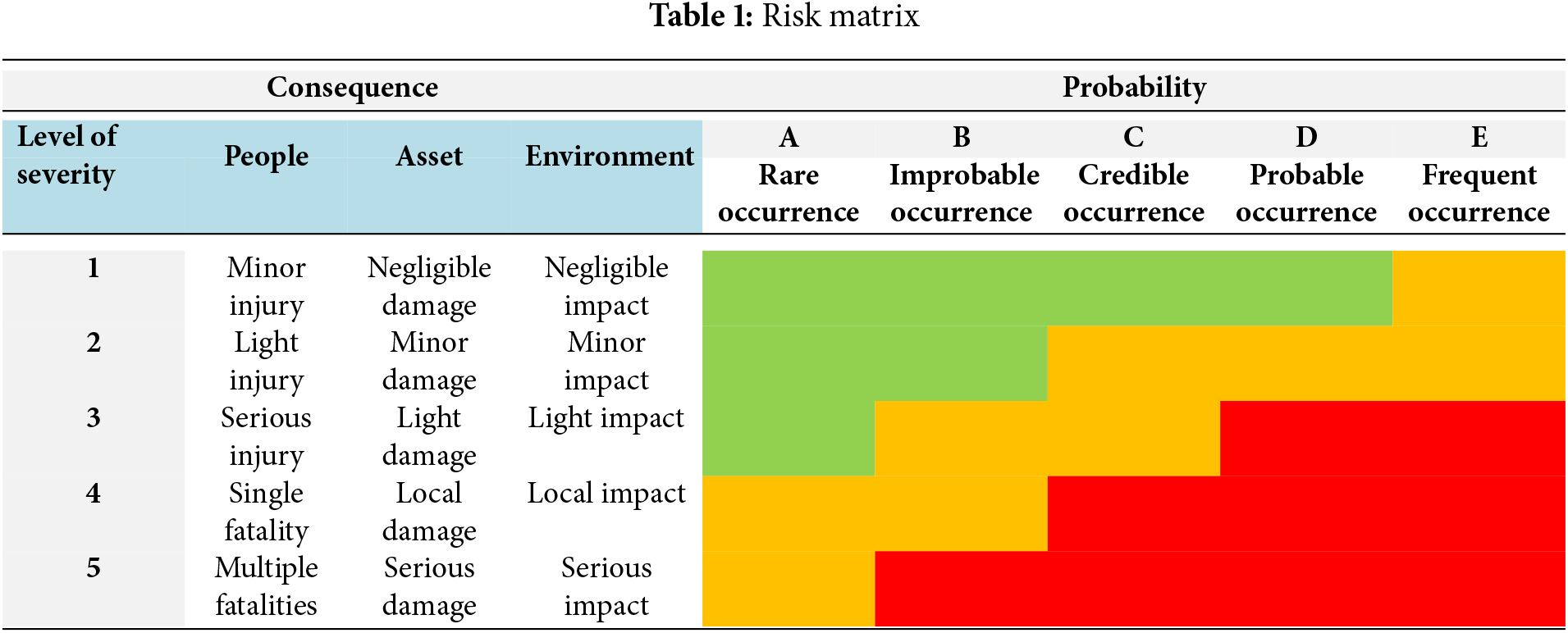
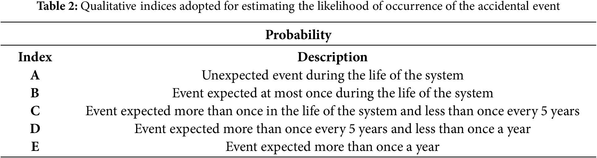
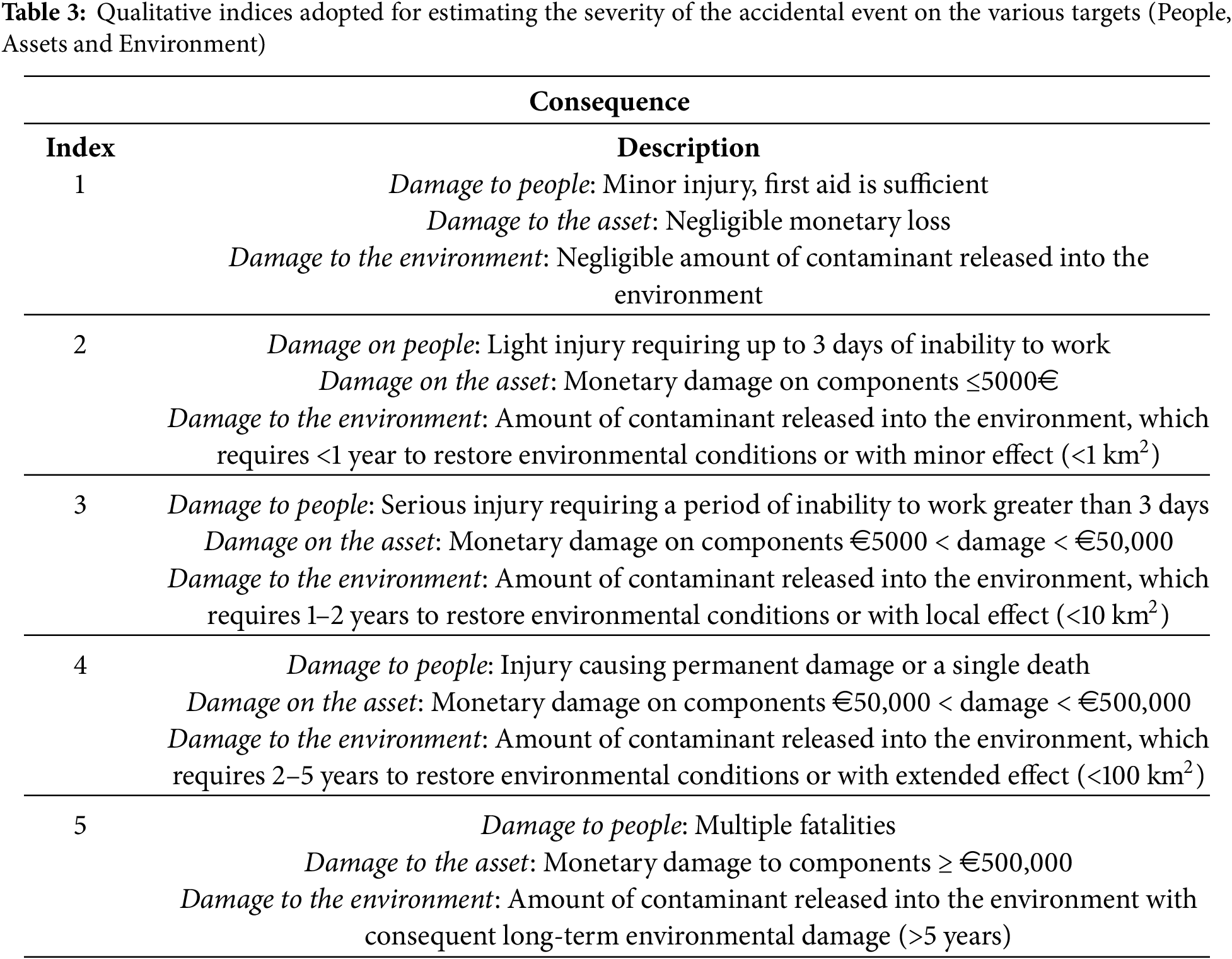
For each identified scenario, the associated risk is assessed using the qualitative risk matrix presented in Table 1. This matrix combines qualitative indices, defined in accordance with relevant standards and industry common practices, to evaluate both the probability of occurrence (likelihood) (Table 2) and the severity of the consequences (Table 3). The risk classification follows three levels:
• Acceptable (green area of the matrix): the risk is characterized by a low probability of occurrence and slight severity impact.
• Unacceptable (red area): the consequences are severe, and the activity must be immediately interrupted until risk reduction measures are put in place.
• ALARP (as low as reasonably practicable) (yellow area): the risk is in between the previous two levels and possible risk reduction measures implementation must undergo a cost-benefit analysis, i.e., the cost of the intervention has not to be highly disproportionate with respect to the provided benefits.
Due to the hazardous nature of the substances present in the plant, the consequences of the high-risk scenarios, particularly those involving a loss of containment, warrant further analysis using a quantitative approach. The objective is to evaluate the potential impact on the structure and equipment, optimize the layout and prevent possible domino effects.
Since many components of the installation are potential sources of flammable or explosive material releases, loss of containment may result from factors such as material defects, improper installation, inadequate maintenance, or external corrosion. It is crucial to carefully select the initiating (top) event(s). This selection considers the most critical components based on the mixture’s pressure, temperature, and the total quantity of gas that could be released in case of a leak.
Once the top event(s) are identified, the impact is simulated using consequence analysis software (for this study: PHAST 8.4 DNVGL), taking into account several factors:
• Characteristics of the released substance (flammability, reactivity, etc.)
• Release conditions (pressure, temperature, aggregation state, etc.)
• Height and direction of the released mixture
• Duration of the release scenario and quantity of released gas
• Environmental conditions (e.g., wind speed and direction, Pasquill atmospheric stability, vertical thermal gradient)
The results are presented in terms of damaged areas and maps of the physical effects of a given scenario that may cause potential harm to people, the environment, and the asset. Specifically, the evaluation of jet fire effects employs the Cone model with Johnson correlation [10], with results expressed in terms of thermal radiation intensity. For explosions, the Baker-Strehlow-Tang model [11] is used, and the results are reported in terms of overpressure.
While this approach aligns with standard industrial design procedures, the consequence analysis has also been performed using an innovative method, the SBAM model. This approach, based on the features of Computational Fluid Dynamics (CFD), enhances the level of detail and accuracy in results, particularly in compacted and congested areas such as platform decks. In fact, the presence of hydrogen in the gas mixture necessitates special consideration due to its buoyancy and inertia effects.
The primary objective of the preliminary environmental analysis of the GREEN1 platform is to identify environmental factors associated with its activities and assess those with significant impacts. Recognizing and managing these environmental aspects is essential not only for mitigating risks but also for guiding platform design, informing technological decisions, and ensuring compliance with environmental objectives.
The environmental assessment follows these steps [8]:
a) Identifying the system’s operational modes
b) Selecting the relevant environmental aspects
c) Evaluating the significance of these aspects
d) Addressing any aspects whose significance does not meet established standards.
The assessment considers the platform’s entire life cycle, including:
• Decommissioning Pre-Reconversion
• Construction and installation of the Post-Conversion plant
• Operation and maintenance
• Post-Reconversion Decommissioning
Steps (a) through (d) are addressed in the following case study application.
The reinjection and production of high-pressure gas involve various potential environmental impacts, ranging from noise and vibrations to CO2 emissions and possible chemical leaks. The preliminary environmental assessment aims to evaluate the significance of these impacts to ensure the overall feasibility and effectiveness of the project.
3.1 Platform and Reservoir Description
GREEN1, the reference platform to be converted, is a six-leg platform originally intended for the extraction of natural gas through four wellheads. It consists of four decks, in addition to the boat landing:
• Lower deck at a height of 11 m above sea level
• Cellar deck at a height of 15 m above sea level
• Mezzanine deck at a height of 18 m above sea level
• Weather deck at a height of 21 m above sea level
The weather deck has an area of 440 m2 (20 m × 22 m), partially occupied by the crane and the technical room containing instrumentations and electrical equipment.
The decks are mostly plated, except for the wellhead area, the muster areas and the boat landing. The platform is unmanned, and consequently, there is no living quarter.
The four wellheads are connected to the production and test manifolds via flowlines; each wellhead is equipped with a HIPPS (High Integrity Pressure Protection System) to protect the downstream systems from possible overpressures.
The platform is also equipped with:
• Lunching trap
• Drain system
• Two generators with their diesel fuel storage
• Vent and Blowdown system
• Hydraulic actuation system
• Fire system and Fire&Gas alarms
Underground storage systems used for temporary gas storage rely on depleted reservoirs with specific characteristics that enable them to trap and store injected gas, allowing for its extraction when needed. These systems can be classified as conventional storage, if previously used as gas reservoirs, semi-conventional storage, if formerly used as oil reservoirs or aquifers, or special storage systems if repurposed from abandoned coal mines. The GREEN1 platform is situated on a depleted gas reservoir and is therefore classified as a conventional storage system.
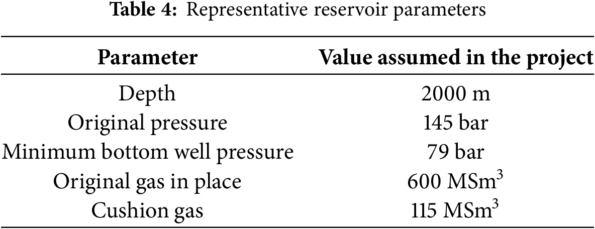
Each reservoir is defined by key geophysical properties, such as initial static pressure and the volume of Original Gas In-Place (OGIP). Since this study is not based on a specific real-life case, the reservoir characteristics were selected to closely resemble those of typical Italian basins, ensuring broader applicability.
The following are significant geophysical parameters considered:
• The reservoir depth influences temperature and pressure, which primarily govern trapping mechanisms, transport, and diffusion phenomena. Additionally, the depth affects the plant design choices like the length of the well, the building materials and the pressure evolution in the well, useful to determine the equipment operative parameters on the platform.
• The original reservoir pressure dictates the maximum allowable pressure at the end of injection phase. Under Italian law, the maximum static bottom pressure during storage operations cannot exceed the reservoir’s original pressure [12].
• The bottom well pressure represents the lowest pressure which can be reached during the extraction phase. It must not fall below the minimum pressure recorded in previous extraction activity.
• The maximum storable gas volume is complex to estimate and cannot be assumed to be equal to the OGIP (Original Gas In Place), as a portion of the gas remains in the depleted reservoir. Determining OGIP and recoverable reserves requires a dedicated reservoir study, including an assessment of internal and external geometry and reservoir rock properties, an analysis that falls beyond the scope of this paper.
More precisely, for this study, the typical reservoir selected is characterized by synthetic parameters derived from five Italian storage reservoirs [13–17]. The corresponding values are provided in Table 4.
3.2 Design Criteria for the New Platform Configuration
The design criteria for the new platform configuration are determined by its operational phases and can be summarized as follows:
• During the regulation phase, the reservoir’s storage capacity shall be maximised while ensuring facility safety.
• During the injection phase, the mass flow from the sealine needs to be sufficient to fill the reservoir at the required pressure within a specified timeframe.
• During the extraction phase, the extracted gas shall be treated to meet national gas grid requirements before being injected into the sealine for distribution to the onshore station.
Based on these objectives, the design criteria for the converted plant are derived from physical parameters specific to the reservoir and the associated aquifer. These parameters result from complex analyses and simulations of the reservoir’s petrophysical and geo-structural characteristics. This paper presents a generic thermo-dynamic model of the reservoir, developed using data from similar projects [17].
To restore the reservoir’s working volume, the regulation phase involves displacing trapped water while maintaining the reservoir’s integrity and stability. This is achieved through successive cycles of gas injection and extraction, progressively increasing the gas volume to adjust the reservoir pressure between its minimum and maximum values. The regulation phase typically requires 8–10 years to establish a stable configuration, enabling consistent gas injection and withdrawal without further changes in the reservoir’s working volume.
During this phase, an increasing amount of gas remains in the reservoir to enhance pressure at the aquifer front and restore the reservoir volume. As shown in Fig. 1, the lower pressure limit (79 bar) is never reached. Additionally, the cushion gas volume must increase to allow gas extraction while maintaining the minimum pressure needed to prevent the aquifer expansion.
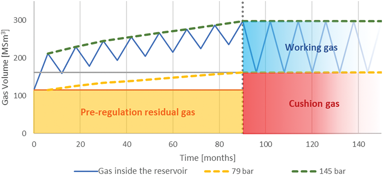
Figure 1: Representation of the gas volume variation during the regulation and initial years of reservoir operation used as an H2-CH4 blend storage/production facility. In yellow and in green are the minimum and maximum pressure values necessary to comply with the reservoir characteristics
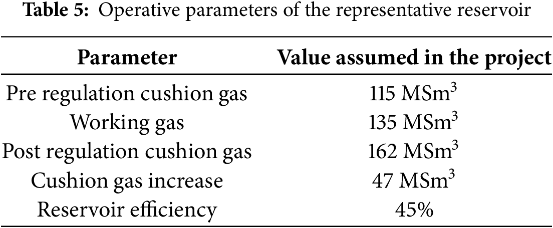
The operational parameters of GREEN1 reservoir are derived from analogous existing reservoirs [13–17] and are listed in Table 5. With these parameters, the reservoir efficiency (calculated as the available working gas over the total gas volume) at the end of the regulation phase is 45%, meeting the Italian regulatory requirement that storage efficiency must exceed 30% [12].
Normal storage operations consist of two main phases:
• Injection phase: gas is injected from the national grid into the reservoir during periods of low demand (typically summer);
• Extraction phase: gas is withdrawn from the reservoir to supply the national grid during periods of high demand (typically winter).
For the injection phase, the key requirement is that the entire working gas volume must be injected into the reservoir within a specified timeframe. This requires a gas compressor capable of processing the mass flowrate and ensuring an outlet pressure sufficient to counteract reservoir pressure and well losses.
Assuming a 6-month injection period, in alignment with other reservoir studies [16,17], the average volumetric flowrate injected through the four wellheads is 0.75 MSm3/day. The mass flowrate varies from a peak of 35,948.26 Sm3/h on the first injection day to a minimum of 26,570.45 Sm3/h on the last day. The injection pressure ranges from a minimum value of 71.50 bar (first day) to a maximum of 130.16 bar (last day). In accordance with [18], each compression unit consists of a centrifugal compressor powered by a gas turbine, which is compact, has low vibrations and distributes horizontal loads across machine supports and the platform structure.
Figs. 2 and 3 show the block diagram of the process. The two layouts highlight the components, and the fluids involved in the two phases of injection and extraction.
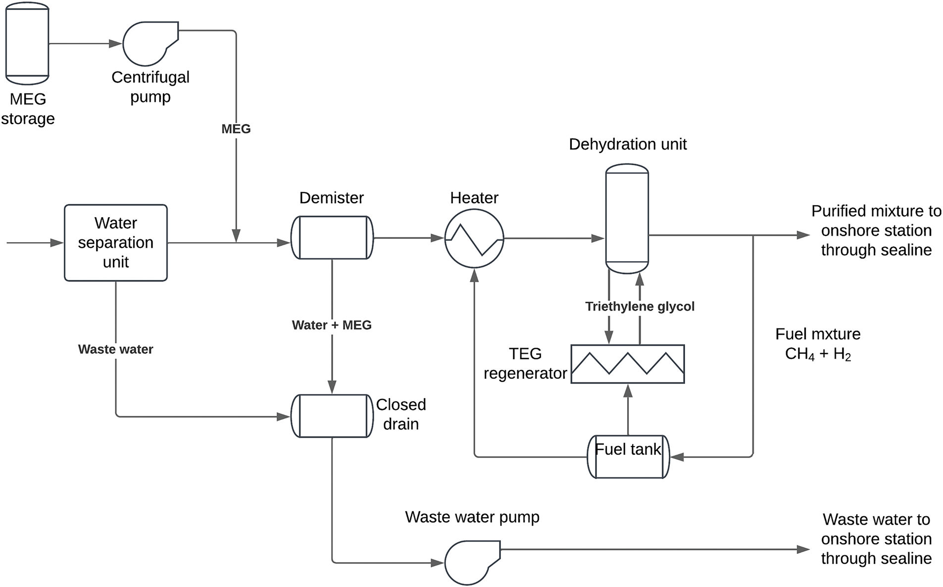
Figure 2: Process block diagram-extraction phase
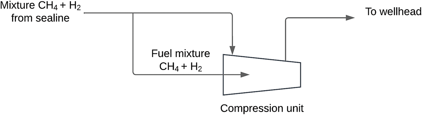
Figure 3: Process block diagram-injection phase
To enhance system availability, two identical compression packages are installed on the GREEN1, operating in parallel and each processing 50% of the total flowrate. The gas turbines powering the compressors are fuelled by the same H2-CH4 mixture injected into the reservoir, with a total fuel consumption of approximately 340 kg/h to operate both packages, equivalent to 1.5% of the platform’s total processed flowrate. Since the gas is sourced directly from the national grid, it is anhydrous and free of significant impurities that could damage the compressors, wellheads, or reservoirs. Consequently, no additional treatment is required.
For the extraction phase, the key criterion is that the entire gas working volume must be extracted and treated to meet national grid quality standards within a defined timeframe. To satisfy this objective, upon extraction after the 4 wellheads, the gas mixture is immediately directed to a separator to remove the water carried from the reservoir, preventing component corrosion, pipeline damage, and small rock sediment accumulation. The separator is designed according to API 12J [19], and during the 6 extraction months, process flowrates ranged from a maximum of 35,951.13 Sm3/h on the first day of extraction to a minimum of 26,583.84 Sm3/h on the last day. Extraction pressure and temperature vary from 129.48 bar and 8°C (first day) to 70 bar and 26°C (last day).
The gas exiting the separator may still contain water droplets which, under high-pressure and low-temperature conditions and with the presence of hydrocarbons, can form hydrates, i.e., solid compounds that can accumulate and damage the downstream separator equipment and pipelines. The most effective technological solution involves injecting a Monoethylene Glycol (MEG) solution into the gas stream immediately downstream of the separator. MEG absorbs residual water due to its hygroscopicity, with an estimated consumption of 15.97 kg/h under worst-case conditions.
The water-rich MEG is then separated by a demister and transported onshore via umbilicals along with the water extracted from the separator. The demister processes a total liquid flow rate of 27.15 kg/h, consisting of 11.18 kg/h of entrained water droplets and 15.97 kg/h of MEG solution. This low flowrate allows the use of a vertical demister, in particular a wire mesh separator with a dense metal mesh capable of capturing droplets as small as 5 µm [20].
To meet national grid specifications, where the dew point at 70 bars must be below −5°C (corresponding to a vapor molar fraction in the gas below 0.0057%), a dehydration unit is used to remove the excess water. This unit employs Triethylene Glycol (TEG), which absorbs humidity from the gas stream through counter-current injection in a dehydration column. The glycol is then regenerated in an atmospheric pressure boiler, where the absorbed water is removed via heating and evaporation [21].
After dehydration, the processed gas is transported onshore via the existing sealine and integrated into the national gas distribution network. The platform is equipped with all necessary auxiliary systems, including a lifting crane for components installation and maintenance, control systems, an uninterruptible power supply (UPS), and fire protection and extinguishing systems. Additionally, the platform features comprehensive instrumentation and communication systems to support operations.
The platform layout has been optimized to minimize deck congestion (Fig. 4).
• The weather deck, the highest and widest deck, primarily accommodates the two packages of the turbo-compressor unit. This placement facilitates installation and maintenance, allows for unrestricted package dimensions, and ensures the safe release of flue gases into the atmosphere. Safety equipment (e.g., PA/GA systems, fireman equipment container), the crane and the telecommunication equipment remain located here.
• The mezzanine deck, situated directly below the weather deck, houses the wellheads, their control panels, and the new technical room, which contains the hardware for the operational and emergency control (DCS and ESD). The technical room’s location minimizes the distance between electronic control and instrumentation for both the turbo compressor unit and the gas treatment units on the lower decks, optimizing the wiring costs and signal efficiency.
• The cellar deck contains the launching trap for cleaning and maintaining the sealine, the separator tank for wastewater-gas mixture physical separation, and the first gas treatment units (MEG package, the demister and the heater). Since a test separator was already present on this deck, this configuration adheres to the principle of minimal structural modification.
• The lower deck hosts the dehydration unit, the TEG regenerator system, and the fuel gas buffer, which support the auxiliary systems in reaching the regimen during the initial extraction phase.
• The boat landing, the lowest deck, contains the closed drain tank for liquid waste generated during the extraction and the pumping system that transfers waste to onshore facilities daily.
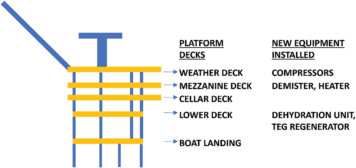
Figure 4: Additions of equipment on the platform decks to convert it into an injection/production unit
All the installed equipment shall be resistant to the harsh marine environment. In particular, metallic components should be tropicalized, meaning they must be galvanized and adapted for the corrosive offshore conditions. Additionally, compatibility checks for materials and components are essential to ensure safe operation with hydrogen, as hydrogen’s permeability, corrosive properties, and unique fluid dynamic behavior in rotating machinery can affect durability and efficiency [22].
The primary objective of the platform conversion is to enable the injection and extraction of the maximum storable volume of 135 MSm3 of H2-CH4 gas at an average volumetric flowrate of 0.75 MSm3/day. In normal conditions, the facility operates continuously, alternating between injection and extraction phases throughout the year. Additional operational modes include:
• Extraction to injection switch: an operational mode remotely activated by the operator when the reservoir reaches minimum pressure at the end of the extraction period or when gas demand decreases, making storage favourable. The process involves closing the extraction valves and the opening injection valves, shutting down and by-passing chemical treatment, and starting the turbo-compressors. All the extraction equipment is safely depressurized, and the residual gas is sent to the flare.
• Injection to extraction switch: an operational mode that mirrors the previous process, remotely activated by the operator when the reservoir reaches maximum pressure at the end of the injection period or when the gas demand increases. It involves stopping the turbo-compressors, closing injection valves, opening extraction valves and lining, and starting the chemical treatment and the auxiliary systems. All the injection equipment is safely depressurized, and the residual gas is sent to the flare.
• Startup: an operational mode occurring during the initial system activation or after a prolonged shutdown, e.g., maintenance. An operator is required on-site to prepare operations, checking valve positions, chemical storage levels, and potential pipeline leaks.
• Shutdown: an operational mode required for extended system downtime, e.g., maintenance. This mode involves closing sealine and wellhead valves, shutting down and isolating turbo-compressor units and chemical treatment units, sending wastewater onshore, and depressurizing lines by directing the gas to the flare.
• Black-out: a sudden power loss scenario in which all the electric components (e.g., pumps, control systems and electric valves) shut down. Wellhead valves passively close to stop the flow and secure the reservoir, the UPS system automatically activates to power emergency lights and alert the technical control room, and shutdown procedures depressurize the lines, directing the gas to the flare.
3.3 Decommissioning and Conversion Civil Works
The decommissioning strategy prioritizes minimizing interventions to optimize the costs. Existing components are only removed if necessary to accommodate new systems or if their weight restricts the installation of new components. Where feasible, existing components are cleaned, secured, and repurposed.
The Weather Deck is dedicated to the new compression package installation. Communication systems, the crane, the fire-fighting system, and the removable wellhead hatch are retained. The technical room, the heaviest component, is relocated to the mezzanine deck to accommodate compressors, and diesel generator packages are removed as they are no longer needed.
The Mezzanine Deck is primarily dedicated to the new technical room. Most pre-conversion components, including the diesel storage tank (the largest), are removed, while the wellheads and control panels remain.
The Cellar Deck houses the initial components of the gas treatment unit. Most pre-conversion components are removed, except for the wellheads, launching trap, and the test separator.
The Lower Deck is reserved for the remaining components of the gas treatment unit. Major pre-conversion components, such as the diesel fuel skid and chemical and corrosion fuel skid, are removed.
Most components on the Boat Landing are reused after remediation and securing, for the purposes of the new configuration. For example, the Closed Drain is repurposed as a wastewater storage tank.
The sealine is retained, as it provides the connection between the national grid and the offshore storage system.
Since new components are installed on the offshore platform, a preliminary comparative structural analysis is conducted to ensure compatibility between the new equipment and the existing platform structure. This deck-by-deck analysis compares the pre- and post-conversion configurations in terms of weight and spatial distribution.
The new configuration results in a total weight reduction of 61 t: while over 140 t of equipment are removed, 80 t are added. Additionally, the load distribution has been optimized, with new components strategically positioned to minimize shear stress on horizontal beams and to align with the four vertical support legs.
Despite the encouraging results obtained since now, a more advanced qualitative mechanical analysis is recommended for subsequent design phases.
Following the new layout design and operational mode definition, an environmental and safety assessment of the proposed configuration is conducted.
Recalling the procedure’s steps listed in Section 2.4, as for step (a), the system’s operational modes considered are: startup, normal operation, daily shutdown and extended shutdown, and maintenance, while for step (b) the following environmental aspects are addressed:
• Emissions of gases and vapours into the atmosphere: for example, emissions into the atmosphere of CO, CO2, particulate matter, vapours due to volatile substances not properly stored;
• Emissions of liquids into the sea: for example, discharges of substances dangerous for marine flora and fauna, continuous discharges of water with altered chemical and physical characteristics;
• Production of waste: for example, waste related to planned or exceptional presence of people onboard, waste from chemical and physical processes;
• Production of noise and vibrations: for example, activities of pumps, compressors and turbines;
• Heat production: for example, the activity of internal combustion engines or steam generators;
• Light pollution: for example, lighting that does not comply with the sleep-wake cycle of aquatic species or potentially dangerous for aircraft;
• Consumption of energy and resources: for example, use of particularly energy-intensive electric machines or use of natural resources.
The impact significance assessment Step (c) considers five criteria: legal constraints, public image, economy, frequency and severity of the effect. A scoring system is introduced for the evaluation of the significance of a potential environmental impact due to each activity.
The results classify four activities as medium environmental risk and thirty-one as low environmental risk, while none are classified as high risk. The medium-risk activities include:
• Compression of the mixture to be stored in the reservoir, relating to the environmental aspect of the emission of gases and vapors into the atmosphere;
• Closed drain waste disposal, relating to the environmental aspect of waste production;
• Compression of the mixture to be stored in the reservoir, related to the environmental aspect of noise and vibration production;
• Use of part of the mixture to feed the compression packages and other auxiliaries, relating to the environmental aspect of consumption of energy and resources.
Step (d) concludes that the converted GREEN1 platform does not exhibit, to the extent of the basic design, environmental aspects of high significance that necessitate immediate environmental improvement or mitigating interventions.
The emission of exhaust gases into the atmosphere, caused by H2-CH4 gas combustion to produce energy for the compression of the mixture to be stored in the reservoir, is a continuous activity and has a medium-size impact on the environment (environmental effects on a local scale); it is worth noting that the height and diameter of the stack of the compression package can be suitably sized to make the dispersion of the gases effective. Moreover, the use of the 10% H2 mixture reduces the production of CO2 during combustion. This environmental impact also presents an economic burden for the company, since the environmental costs corresponding to the tons of the emitted CO2 are quantified, despite the fact that the legal limits are not exceeded. This precaution aims to compensate the possible negative effect to the public image of the organization, especially among a niche of the population attentive to environmental aspects, which opposes to discharges into the atmosphere. For the study case, however, the operations are performed offshore, far from the population, and properly managed with negligible impact.
The production of noise and vibrations due to the activity of the compressors for storing the mixture in the reservoir is a continuous activity and has a medium-sized impact on the environment, due to the centrifugal nature of the compressors. Furthermore, the activity does not impact the organization economically, does not exceed any limit imposed by law, nor does it have a negative effect on the public image of the organization. To limit the effect of the compressors’ activity on the marine ecosystem and on operators in the event of their presence on board, it is recommended to install devices to minimize the transfer of vibrations to the structure (anti-vibration plates) and to provide suitable personal protective equipment and soundproofing devices.
The disposal of closed-drain waste is a continuous activity (it occurs every 15 h) with negligible impact on the environment. Despite this, considering the complexity of the current regulatory landscape, the occasional exceeding of the legal limits during operation could be possible and therefore, as a precaution, the estimation has taken into consideration also this possibility. Moreover, since this wastewater is sent to authorized plants for recovery/disposal, an impact of the cost relating to waste management of around 1% on the budget can be estimated. This activity does not negatively affect the public image of the organization.
The use of part of the mixture to feed the compression packages and other auxiliaries is a continuous activity with negligible environmental effects, considering the low consumption of the plant. Despite this, this activity leads to a non-negligible cost on the balance sheet; the greatest mixture consumption (about 1.5% of the amount received from the national gas grid) occurs during the injection phase to run the compression packages. However, this activity does not affect the public image of the organization, nor does it lead to exceeding the limits imposed by law. For this activity, as well as for the activity related to the emission of the exhaust gas, it is recommended, in the detailed project phase, to evaluate compression system alternatives, based on green technologies, to optimize the consumption of resources and energy recovery and reduce further the CO2 emissions into the atmosphere.
3.5.1 Qualitative Analysis Results
The HAZOP analysis, based on the methodology outlined in Section 2.3.1, primarily considers normal operations during injection and extraction phases, but also extraordinary activities such as maintenance, startup, and shutdown. The HAZOP study identified one-hundred-fourteen hazardous scenarios, but none of the related risks were classified as unacceptable, given the existing safeguards. More than half of the analysed risks were deemed acceptable, while fifty-four were categorized as ALARP, mostly due to their potential impact on people and assets.
Examples of ALARP scenarios per impact category include:
• For on-board operators, the ALARP scenarios are associated with the potential mixture release and ignition, leading to fire and/or explosion.
• For the environment, the ALARP scenarios are related to the release of environmentally dangerous substances or gas mixture via a vent line (the only connection with the external environment).
• For the asset, the ALARP scenarios involve the severe equipment damage, such as a turbo compressor package suction blockage during the injection phase.
A total of twenty-two recommendations were proposed for implementation in subsequent design phases to shift the ALARP risks into the acceptable area. These recommendations include adding new independent safeguards, verifying the technical specification and the operational limits of the equipment, or conducting dedicated quantitative analyses to assess the potential damage.
Examples of proposed safety measures are briefly presented hereafter.
A logic based on the flow differential pressure is recommended during extraction to detect the flow direction and close the buffer connection line before it empties completely. A temperature transmitter is recommended for MEG and TEG dehydration units to detect possible overtemperature in the lines. An auto-shutdown procedure for the turbo compressor unit is suggested during injection in case of blocked suction or discharge. A mixture composition analysis unit is recommended on the package inlet line to trip the system if the gas flow deviates from specifications.
3.5.2 Quantitative Analysis Results
Following the methodology in Section 2.3.2, the guiding principles for conducting a risk assessment during the basic design phase, such in this case for the conversion of the offshore platform, are to estimate the extension of the damage areas for the representative risk scenarios to give preliminary directions to the subsequent detail design phase and to the review of the preliminary platform layout. According to standard engineering practices, scenarios involving containment loss are selected, precisely, jet fire and vapour cloud explosions, and the standard damage curves considered in Quantitative Risk Assessment (QRA) are calculated and plotted.
The quantitative analysis is performed using the consequence simulation tool PHAST 8.4 DNVGL, considering several loss of containment scenarios in terms of released quantity, meteorological conditions and applicable hole sizes. In the following, a specific scenario is assessed, referring to the unit containing the separator and the demister on the cellar deck, considering a release pressure of 129 bar, meteorological condition F2 (Pasquill stability class F, wind speed 2 m/s) and a release hole diameter of ¼ inch. This scenario was chosen due to its higher likelihood compared to larger releases. Small release scenarios are particularly important to analyze since their consequences can usually be mitigated, whereas larger leaks often cause severe damage to the entire platform.
For the selected scenario, in the case of jet fire, two damage areas (see Fig. 5) are considered: the case of thermal radiations of 100 and 37.5 kW/m2 with consequent equipment damage equal to, respectively, 100% and 50%.
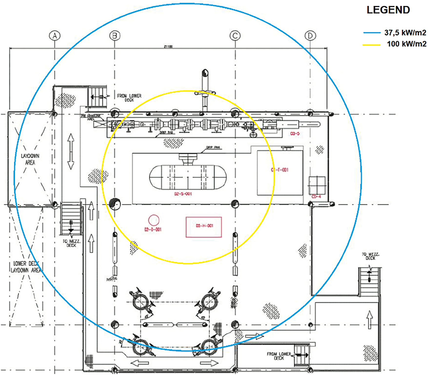
Figure 5: Jet fire damage areas in the cellar deck
It is important to note that, due to the jet fire directionality and the distribution of components, not all items within the damaged areas would be impacted simultaneously.
To mitigate the jet fire effects, an additional shutdown valve was introduced between the separator and the demister, reducing potential release quantities by 50% in case of an accident. With this valve in place, the fire scenario does not reach the 100 kW/m2 radiation threshold.
The Vapor Cloud Explosion (VCE) scenarios are only considered if a flammable vapor cloud forms and later ignites in congested areas designated as Potential Explosion Site (PES) [11]. In the case study, the PES includes the separator, demister, MEG package and heater. The affected areas (see in Fig. 6) were calculated under the assumption that the mass within the PES corresponds respectively to 5%, 50% or 100% of the PES free volume (that is PES volume minus obstacles volume) and represents the area where the blast overpressure reaches 0.3 bar. The amount of gas involved in the three different scenarios are 0.356 kg for the 5% case, 3.559 kg for the 50% case and 7.119 kg for the 100% case.
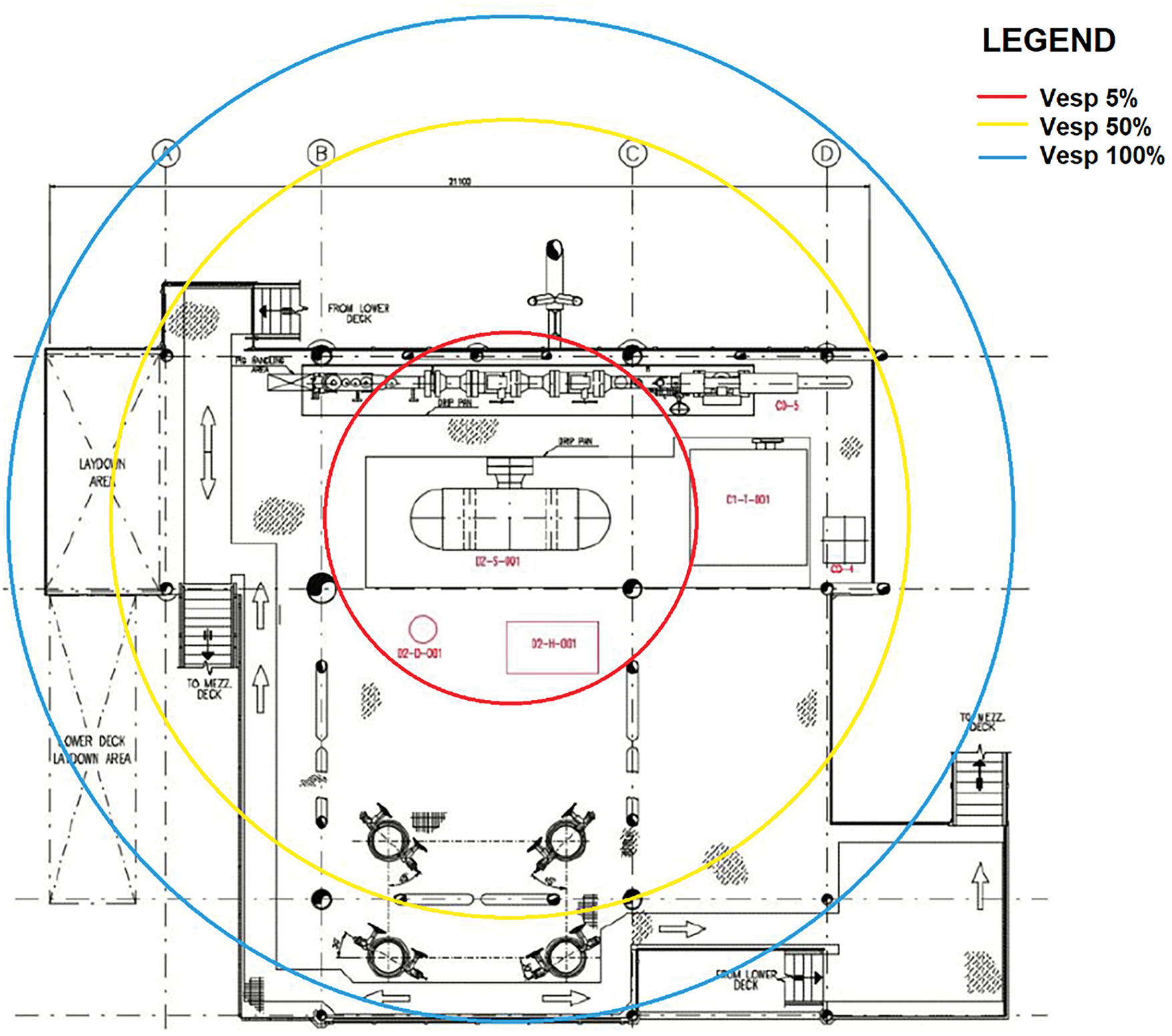
Figure 6: VCE damage areas in the cellar deck
To reduce the effect of the VCE, a layout modification is recommended to redistribute equipment on the deck, enhancing vapor cloud dispersion and preventing explosion scenarios.
As shown in Figs. 5 and 6, conventional simulation tools often predict large damage areas even for relatively small releases. While these tools are user-friendly and computationally efficient, they tend to be overly conservative and to ignore the presence of obstacles in the gas dispersion domain. Overly cautious risk assessments may lead to introduce preventive and correcting measures too conservative which end up to unnecessary protections on an aging platform, increasing costs, complexity, and structural weight. To enhance accuracy, a CFD-based assessment was performed to pinpoint areas where the H2-CH4 mixture could accumulate and potentially trigger a flash fire.
The assessment has made the most of the innovative approach proposed in previous works called the Source Box Accident Model (SBAM Model [23]). The SBAM model is based on the ANSYS Fluent tool and is used for simulating high-pressure gas releases in congested environments. The SBAM model offers a balance between accuracy and computational efficiency by decoupling the accidental event into two phases, the supersonic release near the leak hole and the far-field dispersion, avoiding the difficulties often coming from the implementation of conventional CFD analysis and tools to intricate geometries. In this study, the model was applied for the first time to assess a mixture of H2-CH4.
The analysis is based on the following assumptions:
• Release pressure: Pril = 129 bar
• Blend: 90% CH4–10% H2
• Release hole diameter: dhole = 6.35 mm (1/4 inch)
The platform deck was modeled in SolidWorks 3D CAD, excluding piping for layout simplification (Fig. 7).

Figure 7: CAD 3D of the cellar deck (a, b)
A specific part of the deck modelling is the gridded area corresponding to the area of the wellheads and access stairs to the deck. The red box in the central part of Fig. 8b represents the point from which the incidental release occurs (the source box in the SBAM model). All the simulations were performed in the same domain created using ANSYS Design Modeler. The domain is a 40 m × 40 m × 16 m box in the middle of which the cellar deck of the platform is located.
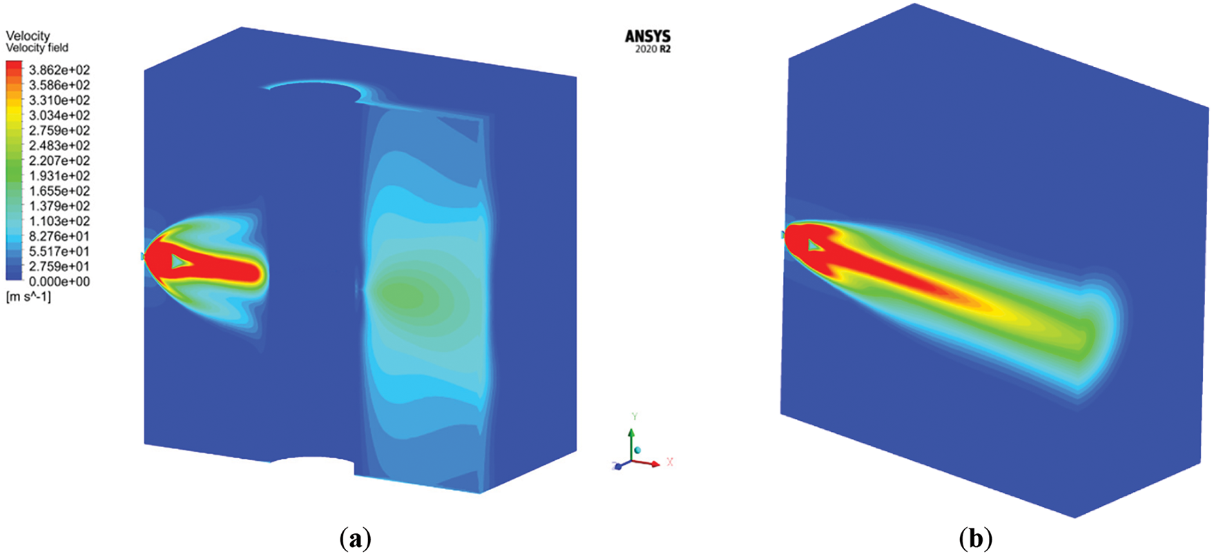
Figure 8: Velocity of the released gas in the SB with obstacle (a) and as a free jet (b)
The computational mesh was made by refining the cell size in the grated area of the domain. In the refinement zones, the cell size is equal to 5 × 10⁻² m while in the outer edges of the domain the cells reach a size of 2 m. Further refinement was imposed on the faces of the red box (the source box), with cell sizes equal to 1 × 10⁻¹ m. The mesh was prepared using ANSYS Meshing and consists of 7 × 10⁶ cells. The grid independence has been checked by means of the Grid Convergence Index (GCI) [24].
Adopting the SBAM model, two simulations were carried out:
• In the Source Box (SB): a release simulation in a reduced domain near the hole where the compressibility and sonic effects of the flow develop until they are exhausted. Velocity and concentration (mass fraction) values are calculated on the surfaces of the SB;
• Out of the SB: a dispersion simulation that takes as inputs the velocity and mass fraction profiles of the released gas and is carried out throughout the fluid domain that is considered subsonic and incompressible.
The governing equations of the phenomena modeled in this approach are the mass conservation equation, the momentum conservation equation, the turbulence closure model, the species transport equation and the energy equation [25]. Where appropriate, for example in the calculation of the density of the gas, the peculiarity of the Source Box as a domain where very high-speed release is developed, compressibility effects have been considered. In the domain deck, instead, incompressible fluid was modeled [23].
Four scenarios were investigated with and without a cylindrical obstacle in front of the release to simulate the congestion of the deck:
• Jet with obstacle with wind velocity vwind = 2 m/s
• Jet with obstacle with vwind = 5 m/s
• Free jet with vwind = 2 m/s
• Free jet with vwind = 5 m/s
Standard wind conditions used in quantitative risk assessments are employed, precisely 5 m/s corresponds to the day condition of stable atmosphere (Pasquill stability class D) and 2 m/s corresponds to the night condition of stable atmosphere (Pasquill stability class F). In both cases the most stable atmospheric conditions are selected, being the most dangerous because the released gas is less diluted and creates flammable clouds of greater volumes for inert or light gases.
The simulation results are graphically presented in 3D images to show the dynamics of the physical events. Indeed, the concentration of the flammable gas in the calculation domain depends on time and position and the 3D image better expresses the spatial trend when the phenomenon reaches steady state conditions, contrarily to a graph that could only give the detail for a specific instant of time and on a single cross-section of the domain.
Two different SB were simulated to account for the two families of scenarios. One involves the presence of a cylindrical obstacle in front of the release hole to simulate the behavior of an uncontrolled jet in a heavily congested plant environment (Fig. 8a). In the second SB a free jet, i.e., without any obstacle, is simulated (Fig. 8b).
The turbulence model used is the k-ω SST (Shear Stress Transport) model including the fluid’s viscous dissipation terms. In these simulations, the “Species Transport” model was implemented [23].
The simulation in the cellar deck concerns the dispersion of the pollutant in an environment where the compressed gas flow is assumed subsonic, and the fluid can be considered incompressible. The phenomenon is analyzed under steady-state conditions. In this simulation, the possible effects of gravity due to buoyancy forces were included. The k-ε RNG turbulence model was used to solve the phenomenon [23].
The solution method adopted for both simulations (in the source box and in the rest of the domain) is a pressure-based coupled algorithm and the formulation for the mass flux computation is the Rhie-Chow distance based [25]. In the Fluent setup, the spatial discretization scheme is the least squares cell based and a second order upwind discretization was chosen for pressure, momentum and energy, while the first order was selected for turbulent kinetic energy and turbulent dissipation rate. As the setting is for a single-phase steady-state problem, the global time step as pseudo time method is chosen with pseudo time explicit relaxation factors that are modified to 0.75 for turbulent kinetic energy and for specific dissipation rate equations, while it is set to 0.8 for the turbulent viscosity.
The simulation needed 2500/3000 steps to converge.
Simulation with Obstacle
The first case considers the presence of an obstacle near the release hole and an atmospheric wind at a velocity of 2 m/s. The presence of the obstacle near the release can be seen from the flow lines trend (Fig. 9a,b), as the jet tends to open and rise along the y-axis and then close several meters away from the hole. On the XZ plane (Fig. 9a), it is possible to observe how the flow field creates some depression zones that guide the flow along with the wind speed, which is the dominant force of the phenomenon.
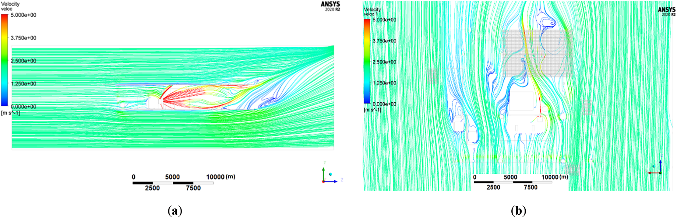
Figure 9: Flow field in the YZ plane (a) and in the XZ plane (b)
The flammable volume remains confined to the area near the release, and significant amounts of hazardous gas trapped in its vicinity can be found (Fig. 10a). On the other hand, it is of particular interest to note that at lower but still relevant concentrations (i.e., above LEL/2) the cloud of contaminated gas splits both in the upper and lower parts of the deck, affecting the areas where wellheads are installed, which is possibly due to the presence of the grated floor (Fig. 10b).
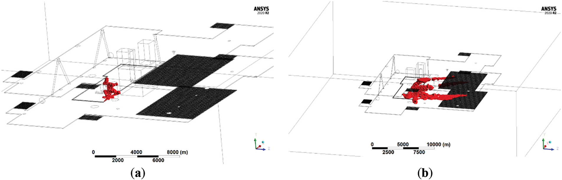
Figure 10: SB with obstacle-Flammable gas volume (a) and volume of the gas cloud with a concentration above LEL/2 (b)
In the case of wind velocity at 5 m/s, very similar results are obtained. The main difference is the flow field which has a flow more directed due to the presence of the wind, which confirms to be a dominant force in the physics of the phenomenon.
Simulations without Obstacles
In this case, the release in the SB is a free jet and the wind velocity is 2 m/s. In Fig. 11a,b, the flow field of the phenomenon is shown. The flammable gas jet is pushed downwards due to the flow of air in the upper part of the cellar deck. The flow lines form a curvature behind the release points due to the presence of the first big obstacle in the domain.
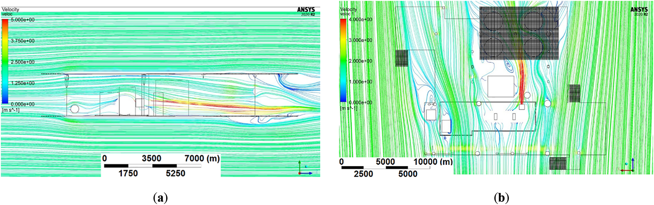
Figure 11: Flow field in the YZ plane (a) and in the XZ plane (b)
Due to the aforementioned flow field, it is possible to see how the flammable volume resulting from the accidental release extends along the Z-axis and affects the wellhead area (Fig. 12a,b). Again, it is of particular interest to visualize the domain volume with a gas concentration greater than LEL/2 as it is possible to appreciate how the H2-CH4 mixture tends to go downwards and cross the grated area in the lower part of the cellar deck.
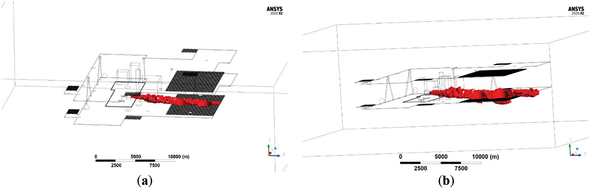
Figure 12: Free jet-Flammable gas volume (a) and volume of the gas cloud with a concentration above LEL/2 (b)
In this scenario, considering the free jet and a wind velocity of 5 m/s, like in the previous case study, with increasing wind velocity magnitude, the flow field is more aligned along the Z-axis, parallel to the wind vector. As a result, the jet containing the hazardous gas release remains more collimated along the release direction. The amount of gas, in flammable conditions, estimated by CFD for the worst case (without obstacle, wind 2 m/s) is 0.058 kg, roughly one order of magnitude lower than the one estimated by PES for the 5% case.
When comparing simulations, it is interesting to note that the free jet case has the closest resemblance to the PHAST simulation shown in Fig. 5, which does not account for obstacles. The application of SBAM which includes the obstacle in front of the release point, resulting in a more realistic representation of the phenomenon in a congested environment, shows a significantly smaller extension of the flammable cloud contributing to the potential jet fire or explosion. In addition, considering the amount of gas contained in the flammable portion of the cloud it can be noted that it is smaller of about one order of magnitude with respect to the one estimated by the PES model; the consequence of this reduction produces a shrinking of the expected damage areas presented in Fig. 6.
CFD simulations reveal that conventional QRA methods significantly overestimate flammable cloud size and damage potential. The SBAM model provides a more realistic risk assessment, reducing the need for excessive structural reinforcements. As a result, CFD should be integrated into early design phases to optimize platform safety measures while minimizing unnecessary modifications.
Repurposing offshore oil and gas platforms is a complex engineering challenge that offers significant benefits by extending the lifespan of these aging structures, aligning them with the energy transition framework.
This study explores the conversion of an offshore platform for seasonal storage of a hydrogen-natural gas mixture in a depleted reservoir beneath it. The platform utilizes existing infrastructure while integrating new equipment to facilitate H2-CH4 mixture injection and extraction, delivering stored gas to the national grid via pre-existing sealines during high-demand winter periods.
Understanding reservoir behavior is essential for ensuring a safe and effective storage facility. With proper regulation and monitoring, the reservoir can provide a secure and substantial storage capacity provided that caution is exercised, and an initial regulation phase is observed to restore the original pressure levels and ensure that pressure limits are not exceeded. A typical reservoir was selected for this basic design, modeled after five Italian storage reservoirs, with a depth of 2000 m, original pressure 145 bar, minimum bottom well pressure 79 bar, original gas in place 600 MSm3 and cushion gas 115 MSm3. Preliminary thermodynamic analysis of the behavior of the reservoir based on the information available on similar projects shows a reservoir efficiency of 45% at the end of the regulation phase, meeting the Italian regulatory requirement of at least 30%. The selection of new equipment follows design criteria ensuring that during the injection phase the entire working volume is injected within a defined time frame and that the entire working volume is extracted all along the duration of the extraction phase and treated to meet the quality requirements. A preliminary layout for injection and extraction is proposed as a foundation for further analysis.
The platform conversion follows design principles aimed at minimizing environmental impact, hazards, and unnecessary costs. The approach prioritizes removing only obsolete or bulky equipment, making space for new installations. The resulting configuration reduces the total platform weight by 61, achieved by removing over 140 t of outdated equipment and installing approximately 80 t of new equipment.
The environmental assessment of the new operations on the platform identified no significant harmful impacts, requiring immediate environmental improvement or mitigating interventions.
Four activities were classified as medium environmental risk with localized effects. Two are related to the compression of the mixture to be stored in the reservoir for potential emission of gases or vapors into the atmosphere or noise and vibration production, one to the closed drain waste disposal and one to the fuel consumption for the compression packages. Recommendations for their reduction are provided in Section 3.4.
The qualitative safety analysis identified one-hundred-fourteen hazardous scenarios, but none were deemed unacceptable. Fewer than half fell into the ALARP area, primarily related to risks affecting people and the environment. This outcome aligns with expectations for a basic design phase, where risk mitigation strategies are still being refined. More than twenty recommendations are proposed to improve the platform safety.
Following the well-established engineering practices adopting a risk-based design approach, a quantitative risk analysis examined the consequences of the loss of containment scenarios of the two representative cases of jet fire and vapor cloud explosion, considering pressure, gas release quantity, meteorological conditions and rupture size. Initially, traditional quantitative risk assessment methods and conventional simulation tools are employed to evaluate the damage areas resulting from the selected scenarios. In the case of jet fire, two damaged areas are considered, for 100 and 37.5 kW/m2 thermal radiation, corresponding to 100% and 50% equipment damage probability. While both damage zones fall within the platform deck domain, jet fire directionality ensures that not all components would be impacted simultaneously. A recommendation is provided to reduce the released quantity during the accident by adding a shutdown valve between the separator and demister, preventing 100 kW/m2 radiation exposure. The VCE scenarios were evaluated only for flammable vapor clouds forming and igniting in congested areas identified as PES. The separator, demister, MEG package, and heater were identified as key PES locations. Also in this case the damage areas fall within the platform boundaries. To reduce the effect of the VCE, a layout modification is suggested to enhance vapor cloud dispersion, preventing explosion scenarios.
While traditional user-friendly risk assessment tools are valuable for fast analysis, they often overestimate damage areas, as they tend to be overly conservative and fail to consider the influence of obstacles in gas dispersion. As the results of these simulations are then used to guide the design of the converted platform, this can lead to excessive safety measures, increasing costs, complexity, and structural weight. For this reason, a more accurate assessment is recommended, based on CFD, to identify more precisely where the H2-CH4 mixture could possibly accumulate. However, detailed CFD simulations are usually very time consuming.
To improve accuracy in predicting accidental consequences from hydrogen-enriched mixtures, the Source Box Accident Model (SBAM) was therefore introduced. This CFD-based approach, optimized for computational efficiency, refines damage area estimates while reducing excessive conservatism in conventional models.
For the first time in this study, the SBAM tool was applied to assess a H2-CH4 mixture behavior into two release scenarios leading to jet fire and VCE. Each case was analyzed with and without an obstructing cylindrical object, simulating real-world deck congestion. In all the four cases, the extension of the flammable cloud contributing to the potential jet fire or explosion when reached the steady-state conditions was significantly smaller than predicted by traditional models, especially in the congested scenario, which represents the most realistic condition. For example, in the free jet scenario the flammable gas volume was reduced by an order of magnitude compared to PES model estimates, leading to smaller damage areas.
The SBAM approach proves to be a valuable tool for optimizing platform conversion, preventing overdesign and avoiding the unnecessary addition of heavy safety measures that could compromise structural integrity.
This study underscores the technical feasibility of repurposing offshore platforms for hydrogen-methane storage, demonstrating that aging offshore infrastructure remains a valuable asset in the energy transition. However, further studies are needed to refine platform layout optimization to prevent domino effects and to enhance safety validation for the entire lifecycle of the converted platform.
Future research directions aim, on one side, to capitalize on the results of this research in order to define a structured guideline for selecting the best conversion strategy for specific off-shore platforms operating on a depleted reservoir. On the other side, the results of the application of the SBAM CFD model on a real case study on H2-CH4 mixtures suggest expanding its application to model fire and explosion phenomena in addition to the release and dispersion models discussed in this paper.
The results of this study provide a strong foundation for future offshore platform conversion projects, contributing to the sustainable repurposing of existing energy infrastructure.
Acknowledgement: The authors are grateful for the active support of Francesco Pertuso, Andrea Tortora, and Gabriele Ballocco throughout the elaboration of the analyses presented in the paper.
Funding Statement: The research presented in this paper was funded by the Italian Ministry of Environment and Energy Security (MASE)—Direzione Generale per le Fonti energetiche e Titoli Abilitativi (DGFTA).
Author Contributions: Study conception and design: Anna Chiara Uggenti, Giorgio Rech, Raffaella Gerboni, Andrea Carpignano, Claudia Vivalda; data collection: Anna Chiara Uggenti, Giorgio Rech, Gianmario Ledda, Amedeo Aliberti, Emanuela Bruno; analysis and interpretation of results: Anna Chiara Uggenti, Giorgio Rech, Gianmario Ledda, Amedeo Aliberti, Emanuela Bruno, Andrea Carpignano; draft manuscript preparation: Anna Chiara Uggenti, Raffaella Gerboni, Amedeo Aliberti, Claudia Vivalda. All authors reviewed the results and approved the final version of the manuscript.
Availability of Data and Materials: The data that support the findings of this study are available from the corresponding author, RG, upon reasonable request.
Ethics Approval: Not applicable.
Conflicts of Interest: The authors declare no conflicts of interest to report regarding the present study.
Abbreviations
| ALARP | As Low As Reasonably Possible |
| CFD | Computational Fluid Dynamics |
| DCS | Distributed Control System |
| ESD | Emergency Shut Down |
| HAZOP | HAZard and OPerability study |
| HIPPS | High Integrity Pressure Protection System |
| LEL | Lower Explosive Limit |
| MEG | Monoethylene Glycol |
| OGIP | Original Gas In Place |
| PV | Photovoltaics |
| SB | Source Box |
| TEG | Triethylene Glycol |
| UPS | UPS Uninterruptible Power Supply |
| VCE | Vapour Cloud Explosion |
References
1. Erdener BC, Sergi B, Guerra OJ, Chueca AL, Pambour K, Brancucci C, et al. A review of technical and regulatory limits for hydrogen blending in natural gas pipelines. Int J Hydrogen Energy. 2023;48(14):5595–617. doi:10.1016/j.ijhydene.2022.10.254. [Google Scholar] [CrossRef]
2. Ozturk M, Dincer I. System development and assessment for green hydrogen generation and blending with natural gas. Energy. 2022;261(B):125233. doi:10.1016/j.energy.2022.125233. [Google Scholar] [CrossRef]
3. Muhammed NS, Haq B, Al Shehri D, Al-Ahmed A, Rahman MM, Zaman E. A review on underground hydrogen storage: insight into geological sites, influencing factors and future outlook. Energy Rep. 2022;8:461–99. doi:10.1016/j.egyr.2021.12.002. [Google Scholar] [CrossRef]
4. Sommer B, Fowler AM, Macreadie PI, Palandro DA, Aziz AC, Booth DJ. Decommissioning of offshore oil and gas structures—environmental opportunities and challenges. Sci Total Environ. 2019;658(10):973–81. doi:10.1016/j.scitotenv.2018.12.193. [Google Scholar] [PubMed] [CrossRef]
5. Scarborough BA, Love MS. Worldwide oil and gas platform decommissioning: a review of practices and reefing options. Ocean Coast Manag. 2019;168(2):274–306. doi:10.1016/j.ocecoaman.2018.10.024. [Google Scholar] [CrossRef]
6. Leporini M, Marchetti B, Corvaro F, Polonara F. Reconversion of offshore oil and gas platforms into renewable energy sites production: assessment of different scenarios. Renew Energy. 2019;135(2–3):1121–32. doi:10.1016/j.renene.2018.12.073. [Google Scholar] [CrossRef]
7. Ministry of Environment and Energy Security. Linee guida nazionali per la dismissione mineraria delle piattaforme per la coltivazione di idrocarburi in mare e delle infrastrutture connesse [National guidelines for the mining decommissioning of offshore oil rigs and related infrastructure]. (19A01522) (GU Serie Generale n.57 del 08-03-2019). Decreto 15 febbraio 2019. Roma, Italy: Ministry of Environment and Energy Security; 2019. (In Italian). [Google Scholar]
8. Uggenti AC, Gerboni R, Carpignano A, Ballocco G, Tortora A, Aliberti A. Definition of a basic design for conversion of an offshore fixed platform on a depleted reservoir into a sustainable plant. ASCE-ASME J Risk Uncertain Eng Syst. 2022;8(4):041101. doi:10.1115/1.4053061. [Google Scholar] [CrossRef]
9. IEC EN 61882. Hazard and operability studies (HAZOP). Geneva, Switzerland: International Electrotechnical Commission; 2016. [Google Scholar]
10. Johnson AD, Brightwell HM, Carsley AJ. A model for predicting the thermal radiation hazards from large-scale horizontally released natural jet fires. Process Saf Environ Prot. 1994;72:157–66. [Google Scholar]
11. Baker WE, Cox PA, Westin PS, Kulesz JJ, Strehlow RA. Explosion hazards and evaluation. Amsterdam, The Netherlands: Elsevier Sience B V; 1983. [Google Scholar]
12. Ministry of Environment and Energy Security. Decreto 4 febbraio 2011 Procedure operative di attuazione del decreto 21 gennaio 2011 e modalità di svolgimento delle attività di stoccaggio e di controllo, ai sensi dell’articolo 13, comma 4 del decreto 21 gennaio 2011. [Italian Ministry of Economic Development, Decree of 4 February 2011 Operational procedures for the implementation of the decree of 21 January 2011 and methods of carrying out storage and control activities, pursuant to Article 13, paragraph 4 of the decree of 21 January 2011] (11A01635) (GU Serie Generale n.40 del 18-02-2011—Suppl. Ordinario n. 43). Roma, Italy: Ministry of Environment and Energy Security; 2011. (In Italian). [Google Scholar]
13. Agip petroli SpA. Relazione di campo—Campo di Barbara NW—Aggiornamento al 31/12/2016 [Agip petroli SpA, Field report—Barbara NW field—Update as of 31/12/2016]. [cited 2023 Feb 20]. Available from: https://va.mite.gov.it/File/Documento/224230. (In Italian). [Google Scholar]
14. Agip petroli SpA. Relazione di campo—Campo di Porto Corsini Mare—Aggiornamento al 31/12/2014 [Agip petroli SpA, Field report—Porto Corsini Mare field—Update as of 31/12/2014]. [cited 2023 Feb 20]. Available from: https://va.mite.gov.it/File/Documento/161093. (In Italian). [Google Scholar]
15. Stogit. Concessione Ripalta Stoccaggio: Relazione tecnica relativa alla sperimentazione in sovrapressione e risultati del monitoraggio [Ripalta Storage Concession: Technical report on overpressure experimentation and monitoring results]. [cited 2023 Feb 20]. Available from: https://va.mite.gov.it/File/Documento/72268. (In Italian). [Google Scholar]
16. Edison Stoccaggio S.p.A. Istanza di concessione stoccaggio gas naturale, Studio di giacimento “Verdicchio” [Application for natural gas storage concession, Study of the “Verdicchio” field]. [cited 2023 Feb 20]. Available from: https://va.mite.gov.it/File/Documento/29260. (In Italian). [Google Scholar]
17. Edison Stoccaggio S.p.A. Studio di giacimento, Trasformazione a stoccaggio del giacimento di Bagnolo Mella [Reservoir study, Transformation to storage of the Bagnolo Mella field]. [cited 2023 Feb 20]. Available from: https://va.mite.gov.it/it-IT/Oggetti/Info/450. (In Italian). [Google Scholar]
18. Stogit. Codice di Stoccaggio di Stogit, Revisione 2022 [Stogit Storage Code, Revision 2022, 2022]. [cited 2024 Nov 27]. Available from: https://www.snam.it/it/i-nostri-business/stoccaggio/codice-di-stoccaggio-tariffe-e-area-comitato/codice-stoccaggio.html. (In Italian). [Google Scholar]
19. API SPEC 12J: 2008 (R2023). Specification for oil and gas separators. Washington, DC, USA: American Petroleum Institute; 2023. [Google Scholar]
20. Nitsche M, Gbadamosi R. Practical column design guide. Berlin/Heidelberg, Germany: Springer; 2017. doi:10.1007/978-3-319-51688-2. [Google Scholar] [CrossRef]
21. Bahadori A, Vuthaluru H. Simple methodology for sizing of absorbers for TEG (triethylene glycol) gas dehydration systems. Energy. 2009;34(11):1910–6. doi:10.1016/j.energy.2009.07.047. [Google Scholar] [CrossRef]
22. Modorskii VY, Cherepanov IE. Influence of methane-hydrogen mixture characteristics on compressor vibrations. Fluid Dyn Mater Process. 2024;20(5):1031–43. doi:10.32604/fdmp.2024.048494. [Google Scholar] [CrossRef]
23. Moscatello A, Uggenti AC, Gerboni R, Carpignano A. A novel approach to high-pressure gas releases simulations. J Loss Prev Process Ind. 2021;72(3):104531. doi:10.1016/j.jlp.2021.104531. [Google Scholar] [CrossRef]
24. Moscatello A, Gerboni R, Ledda G, Uggenti AC, Piselli A, Carpignano A. CFD gas release model performance evaluation through wind tunnel experiments. J Loss Prev Process Ind. 2022;75(3):104715. doi:10.1016/j.jlp.2021.104715. [Google Scholar] [CrossRef]
25. ANSYS. ANSYS fluent theory guide; 2024 [cited 2025 Jan 27]. Available from: https://ansyshelp.ansys.com/public/account/secured?returnurl=////Views/Secured/corp/v242/en/flu_th/flu_th.html. [Google Scholar]
Cite This Article
 Copyright © 2025 The Author(s). Published by Tech Science Press.
This work is licensed under a Creative Commons Attribution 4.0 International License , which permits unrestricted use, distribution, and reproduction in any medium, provided the original work is properly cited.
 Downloads
 Citation Tools