
 Submit a Paper
 Propose a Special lssue
 Open Access
ARTICLE

Numerical Simulation of the Atomization Process for Blast Furnace Slag Granulation
Hebei Key of Laboratory of Intelligence Equipment Digitalize Design and Process Simulation, Tangshan University, Tangshan, 063000, China
* Corresponding Author: Li-Li Wang. Email:
Fluid Dynamics & Materials Processing 2025, 21(6), 1489-1503. https://doi.org/10.32604/fdmp.2025.061154
Received 18 November 2024; Accepted 28 February 2025; Issue published 30 June 2025
 View Full Text
 Download PDF
Abstract
The so-called close-coupled gas atomization process involves melting a metal and using a high-pressure gas jet positioned close to the melt stream to rapidly break it into fine, spherical powder particles. This technique, adapted for blast furnace slag granulation using a circular seam nozzle, typically aims to produce solid slag particles sized 30–140 µm, thereby allowing the utilization of slag as a resource. This study explores the atomization dynamics of liquid blast furnace slag, focusing on the effects of atomization pressure. Primary atomization is simulated using a combination of the Volume of Fluid (VOF) method and the Shear Stress Transport k-ω turbulence model, while secondary atomization is analyzed through the Discrete Phase Model (DPM). The results reveal that primary atomization progresses in three stages: the slag column transforms into an umbrella-shaped liquid film, whose leading edge fragments into particles while forming a cavity-like structure, which is eventually torn into ligaments. This primary deformation is driven by the interplay of airflow velocity in the recirculation zone and the guide tube outlet pressure (Fp). Increasing the atomization pressure amplifies airflow velocity, recirculation zone size, expansion and shock waves, though the guide tube outlet pressure variations remain irregular. Notably, at 4.5 MPa, the primary deformation is most pronounced. Secondary atomization yields finer slag particles as a result of more vigorous primary atomization. For this pressure, the smallest average particle size and the highest yield of particles within the target range (30–140 µm) are achieved.Keywords
Blast furnace slag (BFS) is a byproduct of the iron production process, whose annual global emission is about 325–390 million tons [1]. BFS utilization rates differ in different countries, such that in some countries, this rate exceeds 90%, and in some others, it is less than 60%, which is mainly used as cement clinker [2]. Unused BFS causes considerable environmental pollution and resource waste [3,4]. The chemical composition of BFS mainly consists of SiO2, CaO, Al2O3, and MgO [5], which can form a glass phase when BFS is granulated into particles, and granulated slag can be used as a high-value-added material. Therefore, granulation technology is of particular significance in the slag treatment field [6]. Granulation technology includes two steps: first, liquid BFS is broken up into some ligaments. Second, ligaments are broken up into a large number of droplets, which exchange heat with a medium and solidify into solid particles [7]. Currently, water quenching, gas quenching, and centrifugal granulation methods are the most commonly applied granulation techniques [8]. The slag particles generated by the above three methods are coarse with average diameters of 2–3, 0.5–3 and 0.2–3 mm, respectively, which limits the application of BFS [9–12]. All these slag types have glass phase contents of above 95% [13].
Particles with diameters of smaller than 0.4 mm are called microbeads, which can be considered high-performance silicate materials since they have the advantages of transparency, directional reflection, smooth surface, satisfactory flowability, electrical insulation, adjustable refractive index, stable chemical properties, high heat resistance, and high mechanical strength [14]. Glass microbeads with diameter range of 30–140 µm are extensively being applied. For example, glass microbeads with diameters of 40–60 µm could be employed as reflective materials, those sized 60–80 µm could be applied as filler materials, and those with size range of 100–140 µm could be used as fire-resistant coatings [15].
The gas atomization method with a close-coupled nozzle is commonly used in powder metallurgy due to its high atomization efficiency, low cost, narrow particle size distribution, and satisfactory sphericity [16,17]. In a closed atomization chamber, high-temperature melt is instantly broken up by high-speed gas jets, resulting in the simultaneous production of liquid film, liquid ligaments, and particles with different physical states. Atomization experiments can obtain solid particles and measure particle size, but it is difficult to accurately observe melt deformation due to a complex atomization environment. Several researchers have applied computational fluid dynamics (CFD) to simulate the atomization process and investigate atomization theory. Wang et al. [18] studied the atomization model of a close-coupled ring-hole nozzle, which was used to produce 316 L stainless steel powder. Liu et al. [19] performed a simulation to study close-coupled gas atomization employed to produce Fe-based amorphous powder. Zeoli et al. [20] applied the volume of fluid (VOF) method and discrete phase model (DPM) for the simulation of primary atomization and metal droplet disintegration. Xiao et al. [21] simulated the primary atomization of a liquid jet using the coupled level set VOF method and the broken-up process of a single droplet using a large eddy. Liu et al. [22] employed shear stress transport turbulence (SST k-ω) and VOF models to predict the flow behaviors of metallic melts in delivery tubes. The related literature indicated that melt disintegration involved primary and secondary atomization processes [19,23], where atomization pressure was the most important influencing factor [24,25].
To obtain fine particles, a close-coupled circular seam nozzle was introduced into granulation technology. This research conducted a numerical simulation to investigate BFS atomization, measured particle size distribution of granulated slag, and revealed the influence of atomization pressure on particle size distribution. A close-coupled circular seam nozzle was introduced into granulate BFS, which opened up a new path for BFS granulation and provided important technical support for BFS utilization.
2.1 Atomization Parameters and Simulation Settings
The applied close-coupled circular seam nozzle is illustrated in Fig. 1a, and the longitudinal section of the nozzle center is presented in Fig. 1b. Airflow jet angle α was 36°, circular seam width was 0.5 mm, guide tube elongation was 3 mm, guide tube length was 40 mm, and guide tube diameter was 6.8 mm. Atomization pressures were 2.5, 4.5, and 6.5 MPa. Air served as atomization gas to break up liquid slag, whose physical parameters are summarized in Table 1, and the melt mass flow rate was 0.167 kg/s.
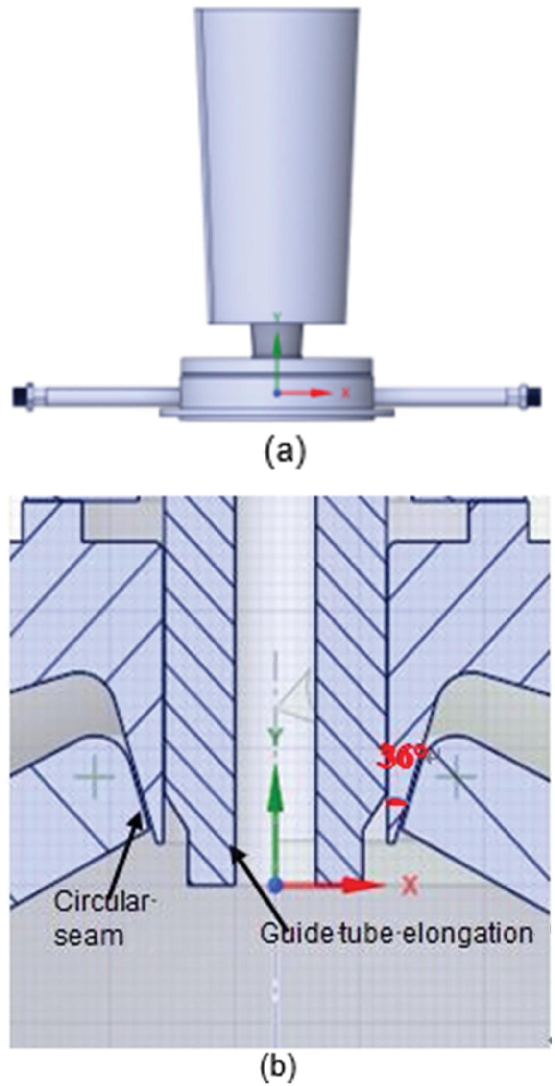
Figure 1: Close-coupled circular seam nozzle: (a) Overall appearance and (b) localized enlargement of nozzle
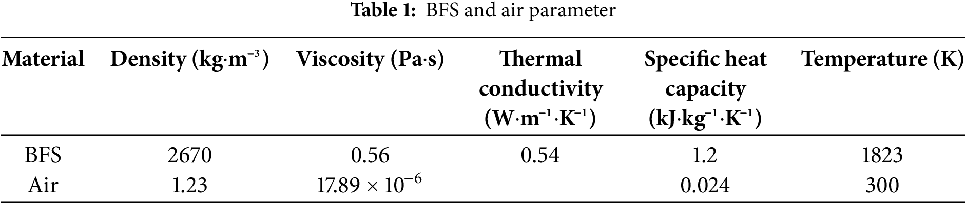
In this research, ANSYS ICEM CFD 2024 R1 software was employed for meshing and ANSYS Fluent 2024 R1 was applied for simulation. Also, a 2D symmetrical model was adopted for calculations because the flow field was symmetrical. VOF model coupled with SST k-ω turbulence model was employed for the simulation of primary atomization, pressure-velocity coupling adopted SIMPLE scheme, pressure discretization was performed based on PRESTO, volume fraction discretization was conducted based on compressive, and second-order upwind scheme was used to obtain density, momentum, volume fraction, turbulent kinetic energy, specific dissipation rate, and energy. The length and width of the computational domain were 300 and 120 mm, respectively, and the entire computational domain was divided by structured mesh. The mesh was densified at the airflow outlet and around the guide tube outlet to generate substantial pressure and velocity gradients. The following six mesh numbers were adopted for the verification of mesh independence at the atomization pressure of 6.5 MPa: 1 × 10⁵, 1.5 × 10⁵, 2 × 10⁵, 2.5 × 10⁵, 3 × 10⁵, and 3.5 × 10⁵. Airflow velocity at the center point of the recirculation zone and the average diameter of particles calculated for each mesh are summarized in Table 2. When the mesh number exceeded 2.5 × 10⁵, airflow velocity and average diameter of particles remained almost unchanged. Therefore, mesh number was determined to be 2.5 × 10⁵.
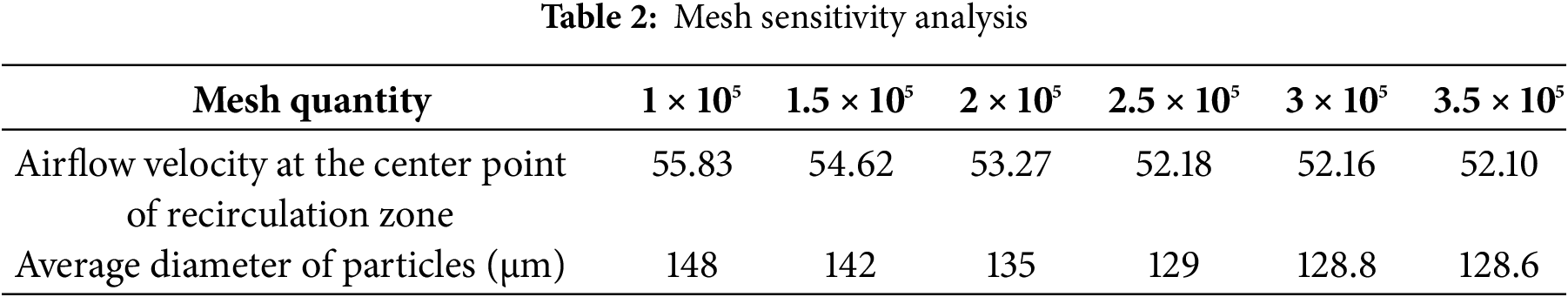
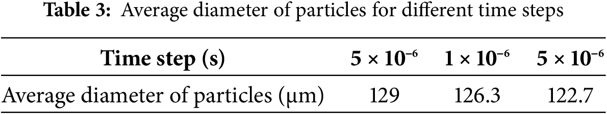
Fig. 2 shows boundary conditions and mesh division. Secondary atomization was simulated by DPM and Kelvin–Helmholtz–Rayleigh–Taylor models. Nozzle exit airflow velocity reached supersonic speed due to high atomization pressure. When the time step was greater than 1 × 10⁻⁵ s, the data were discrete during the calculation and simulation could not be carried out. Therefore, 5 × 10⁻⁶, 1 × 10⁻⁶, and 5 × 10⁻⁷ s were adopted to determine the most suitable time step, and the sensitivity analysis of time step size is summarized in Table 3. For 5 × 10⁻⁶ and 5 × 10⁻⁷ s, the change in average diameter was only 4.88%. Considering computation speed and operating cost, the time step size was determined to be 5 × 10⁻⁶.
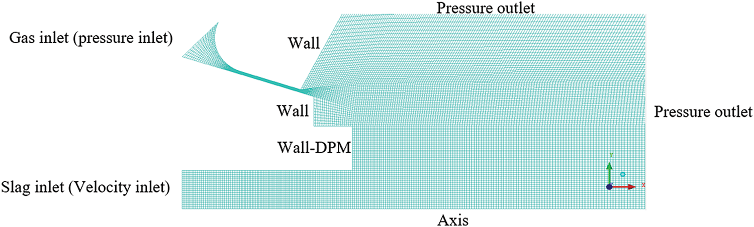
Figure 2: Mesh division and boundary conditions
To validate the accuracy of the developed method and the reliability of simulations, close-coupled gas atomization experiments were performed at the atomization pressure of 6.5 MPa. Particle size distribution was measured by a laser-diffraction particle-size analyzer (BT-9300S). Fig. 3 compares particle size distributions obtained from experiments and simulations. The simulated particle size distributions agreed with experimental results, which validated the accuracy and reliability of the simulations.
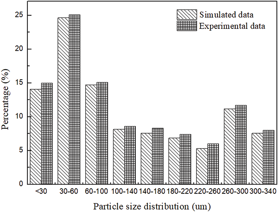
Figure 3: Comparison of particle size distribution results obtained from experiments and simulations
Fluid control equations included mass conservation equation, momentum conservation equation, and energy conservation equation.
Mass conservation equation was defined as [26]:
momentum conservation equation was [27]:
and energy conservation equation was stated as [28]:
VOF model was able to capture liquid slag deformation, SST k-ω model accurately captured free shear flow in supersonic, and DPM was used to calculate granulation results.
VOF equation was defined as [29]:
k-ω SST model equation was expressed as [30]:
and DPM equation was stated as [29]:
In the above equations, xi, xj, xk are three directional vectors and ui, uj and uk are velocities along xi, xj and xk directions, respectively; δij is Kronecker delta function, with the value of 0 because of i ≠ j; Fs is surface tension term; FD is drag force, g is gravitational acceleration, with the value of 9.8 m/s; μ represents dynamic viscosity; μt represents turbulent viscosity; aq is liquid phase volume fraction; k is turbulent kinetic energy, with the value of 1 m2/s2; ω is specific dissipation rate, with the value of 1 s−1; Gk is turbulent energy generation term; Gω is turbulent dissipation rate generation term; Clim is limiting factor, with the value of 0.5; and ρε is turbulent dissipation rate. Turbulent intensity was 5%, and turbulent viscosity ratio was 10.
To set up a flow model, the following assumptions were made:
(1) Atomization gas was treated as a compressible ideal gas.
(2) The mass flow rate of melt was unchanged during the whole simulation.
(3) All walls were considered to be smooth, nonslip, and adiabatic.
The gas flow field determines melt deformation and the entire atomization. The simulation was performed with 3 mm guide tube elongation under 2.5 MPa atomization pressure. The airflow velocity cloud and velocity vector are presented in Fig. 4a and b, respectively. As a result of the presence of guide tube and pressure differential, gas jet formed a chain-like structure with alternating expansion and compression waves and gas recirculation zones were generated at the inner sides of both gas jets. When the upward recirculated gas approached guide tube bottom and contacted liquid slag, the downward flow of liquid slag was hindered, gas was forced to change flow direction, gas direction was changed to radial direction from inside to outside, liquid slag was dragged and squeezed by recirculated gas, and liquid slag could only continue to flow along radial direction without resistance.
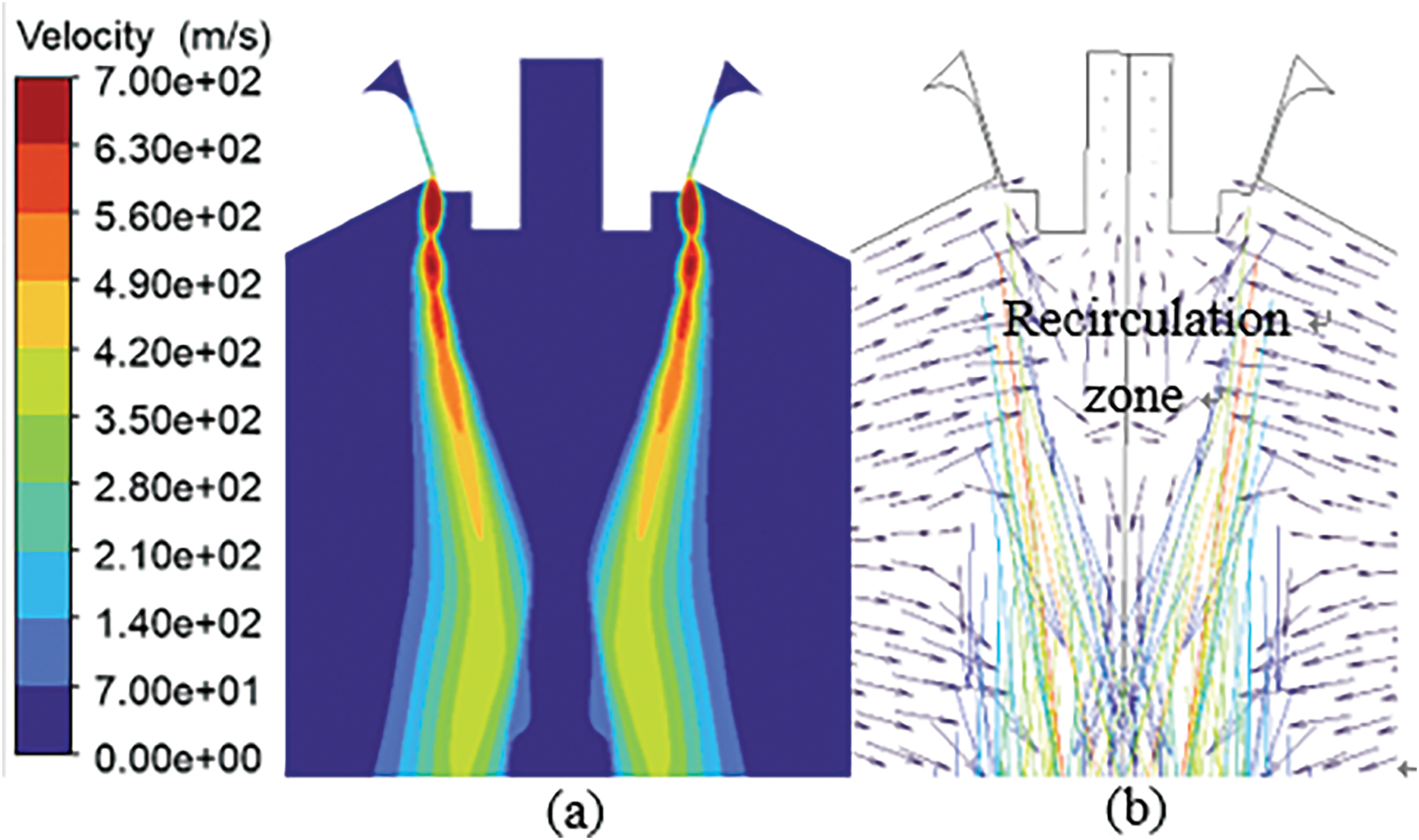
Figure 4: Diagrams of (a) velocity cloud and (b) velocity vector
Under the action of recirculated gas, a liquid film was formed at the bottom of the liquid column. The liquid film extended radially and its thickness was gradually decreased, as illustrated in Fig. 5a. The liquid film extending to gas jet was broken up by high-speed airflow forming droplets. At the same time, the recirculated gas continued to squeeze liquid slag at the lower part of the guide tube and caused the formation of an umbrella-shaped structure, as presented in Fig. 5b. The liquid film front end was constantly broken up by gas jets, and liquid slag continuously flowed downwards, which turned the umbrella-shaped structure into a cavity-shaped one, as illustrated in Fig. 5c. The cavity was shrunk by downward flowing slag, the gas inside the cavity ran away outward, the slag around the cavity was torn into liquid ligaments by escaped gas, and liquid ligaments were broken up into droplets, as presented in Fig. 5d,e. Then, the bottom of the liquid flow formed an umbrella-shaped structure again, as shown in Fig. 5f, which ultimately completed primary atomization.
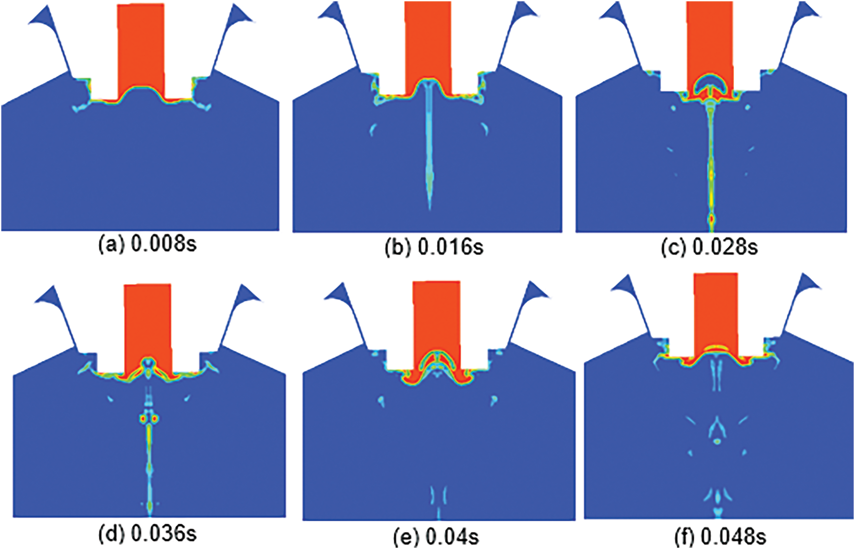
Figure 5: Molten slag deformation at different times
3.2 Effects of Atomization Pressure on Airflow Velocity
Guide tube elongation remained unchanged. Atomization pressures were set at 2.5, 4.5, and 6.5 MPa. When atomization pressure was 2.5 MPa, airflow velocity inside the atomization chamber was low, the generated expansion wave was small, and the recirculation zone was narrow and short and took on the shape of an inverted cone, as illustrated in Fig. 6a. The generated expansion wave and recirculation zone were gradually increased with the increase of atomization pressure, as presented in Fig. 6b,c. When atomization pressure was increased to 6.5 MPa, airflow velocity was the greatest, the generated expansion waves were the strongest, and recirculation zone areas were the largest, as shown in Fig. 6c. The maximum airflow velocity change took place from 700 to 742 m/s. The average airflow velocity in the recirculation zone changed from 11.7 to 23.1 m/s. The length of the recirculation zone was increased from 15 to 25.7 mm, and its width was increased from 15.4 to 20.7 mm. Airflow velocity plays a key role in primary atomization. The aerodynamic force overcame surface tension, inertia force, and viscosity force, ultimately achieving liquid slag deformation. High airflow velocity had high disturbance kinetic energy. Disturbance kinetic energy overcame the work performed by liquid internal forces, causing liquid instability and generating surface waves. Also, the liquid film broke up into ligaments, and the ligaments broke up into droplets at wave valley.
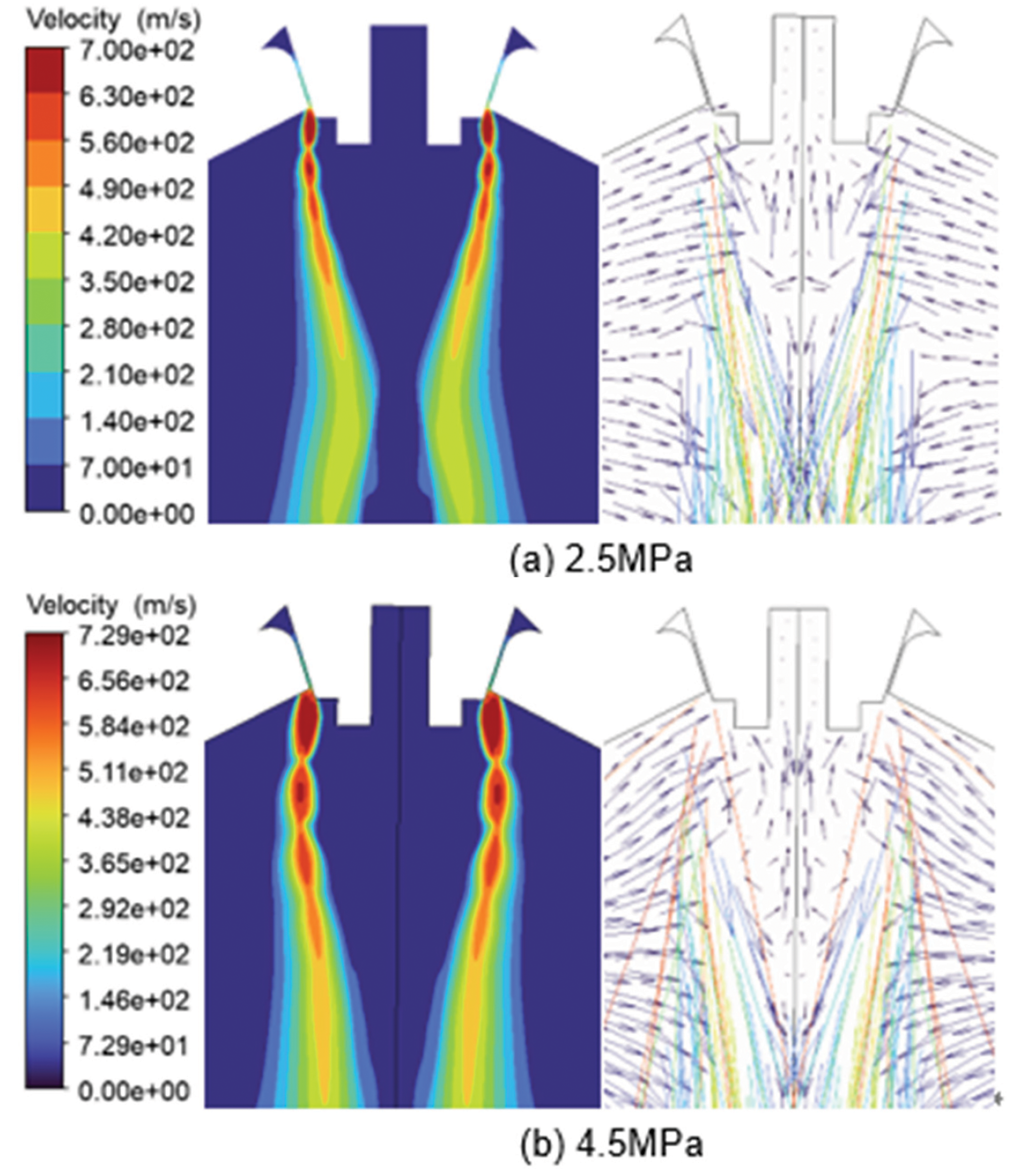
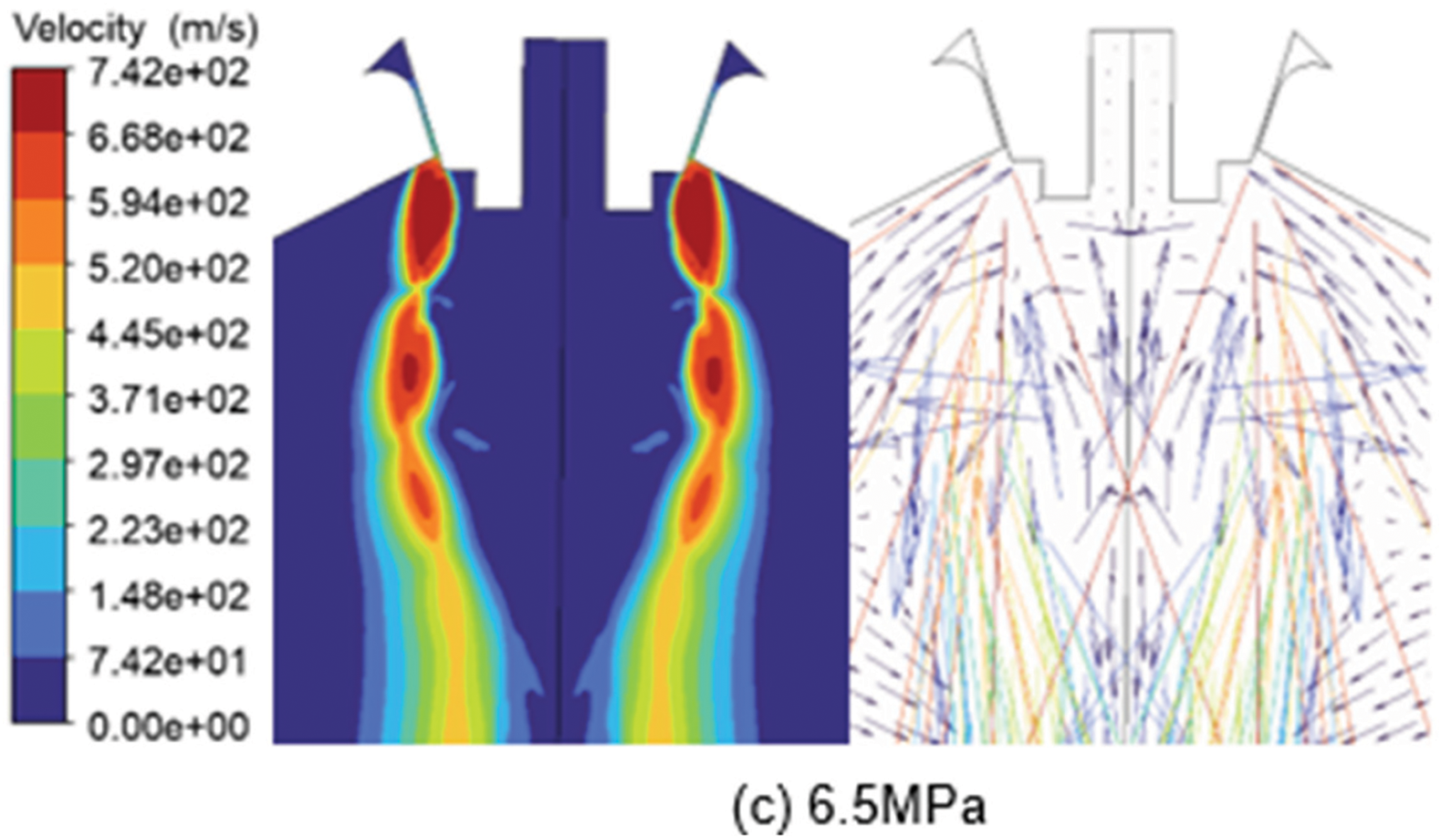
Figure 6: Velocity clouds and vector diagrams under different atomization pressures
3.3 Effects of Atomization Pressure on Guide Tube Outlet Pressure (Fp)
The pressure field is of significant importance because it affects liquid slag deformation. Fig. 7 illustrates pressure clouds under different atomization pressures. Under atomization pressures of 2.5 and 6.5 MPa, guide tube outlet pressures were negative with the values of −0.015 and −0.027 MPa, respectively, as presented in Fig. 7a,c. However, when atomization pressure was 4.5 MPa, guide tube outlet pressure was positive with the value was 0.0097 MPa, as shown in Fig. 7b.
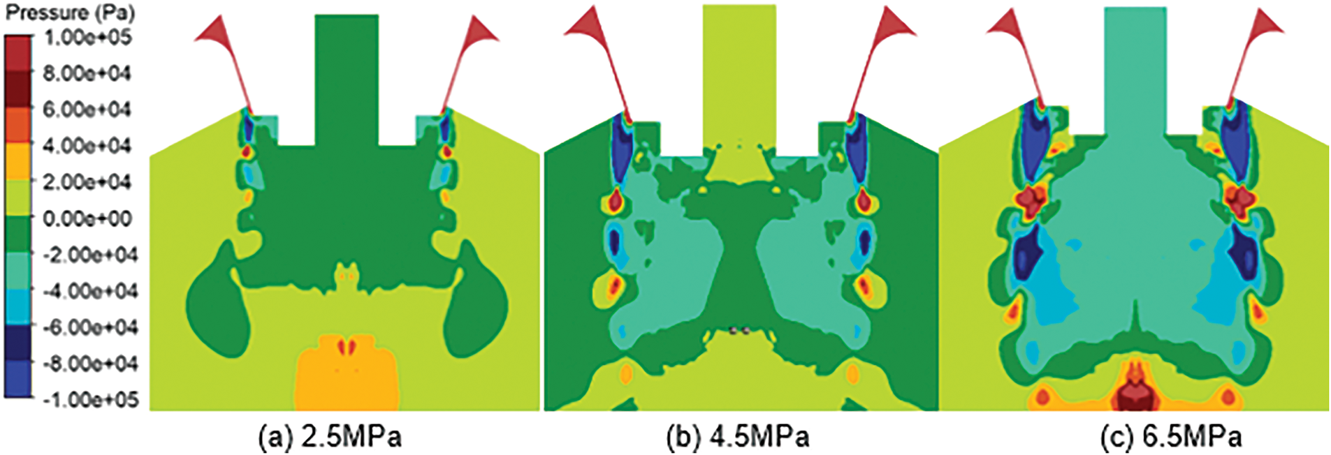
Figure 7: Pressure clouds under different atomization pressures
Fig. 8 illustrates slag shapes under different atomization pressures at 0.018 s. An umbrella-shaped structure was especially evident at the atomization pressure of 4.5 MPa, as shown in Fig. 8b, and was the least apparent at the atomization pressure of 6.5 MPa, as presented in Fig. 8c. Also, the umbrella-shaped structure at the atomization pressure of 2.5 MPa is shown in Fig. 8a. The umbrella-shaped structure was less noticeable under larger negative pressures in this situation. The bottom of liquid slag was mainly affected by the four forces of gravity (Fg), pressure (Fp), buoyancy (Ff), and drag (FD). Fg was constant because the melt mass flow rate was constant. FD could also be considered as constant because liquid velocity was extremely slow compared to high-speed airflow. Fig. 8b,c shows the forces on the bottom of the liquid slag. When guide tube outlet pressure was positive, the relationship of the four forces was Fp + Ff > Fg + FD where the upward force at the liquid core was greater than downward force, causing the melt to be pushed upward and ultimately forming an umbrella-shaped structure. When guide tube outlet pressure was negative, the relationship was Ff < Fg + FD + Fp where the downward force was greater than the upward force, which sucked out more liquid slag. This increased the mass flow rate of the extracted slag and enhanced deformation resistance; therefore, it was difficult to form an umbrella-shaped structure. Hence, primary deformation was influenced by the combined effect of airflow velocity and guide tube outlet pressure. Atomization pressure of 4.5 MPa was the optimum value for primary atomization. If positive pressure was extremely high, a return spray phenomenon occurred inside the guide pipe and liquid slag could not flow out or granulated by the gas.
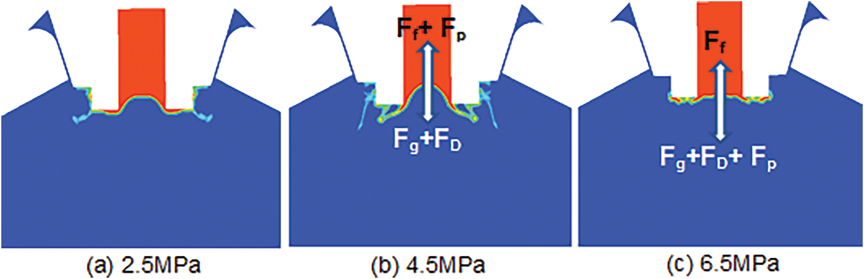
Figure 8: Slag shapes under different atomization pressures at 0.018 s
3.4 Effects of Atomization Pressure on Secondary Atomization
Fig. 9 presents the diameter and velocity of particles at the same time under constant mass flow rate and different atomization pressures. Large particles were distributed on both sides of the axis, and small particles were distributed in the gas jet inside. Although airflow velocity was slow on both axis sides, it was fast in the gas jet inside. The airflow velocity is faster, disturbance kinetic energy is greater, the breakup capacity is stronger, and the particle size is smaller. Particle velocity distribution was opposite to particle diameter distribution and was consistent with airflow velocity distribution.
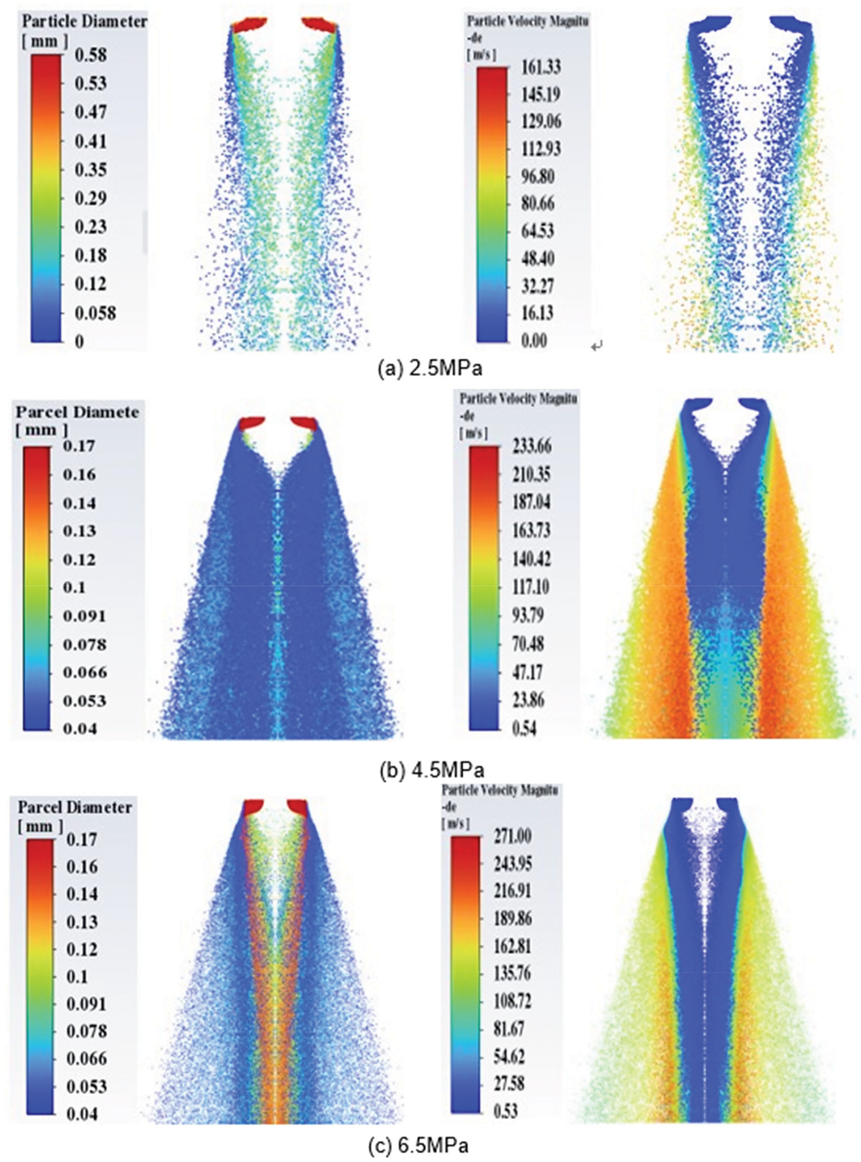
Figure 9: Diameter and velocity of particle cloud pictures
When atomization pressure was 2.5 MPa, particle number was the smallest and atomization efficiency was the lowest, as presented in Fig. 9a. When atomization pressure was 6.5 MPa, particle number was substantially increased compared with that at 2.5 MPa, but the number of large particles was significantly increased, especially on both axis sides, as illustrated in Fig. 9c. When the atomization pressure was 4.5 MPa, particle number was the maximum, the number of small particles was the highest, and the atomization effect was the best, as presented in Fig. 9b.
The variations of average diameter and 30–140 µm yield under different atomization pressures are illustrated in Fig. 10 and particle size distribution is presented in Fig. 11. At guide tube elongation of 3 mm and an atomization pressure of 4.5 MPa, the average diameter was the smallest and 30–140 µm yield was the highest. At the atomization pressure of 2.5 MPa, particle size was mainly distributed within 100–300 µm, the average diameter was greater than 200 µm, and 30–140 µm yield was 17.5%. At the atomization pressure of 4.5 MPa, particle size was mainly distributed within 30–140 µm, the average diameter was only 62 µm, and 30–140 µm yield was 71.7%. At the atomization pressure of 6.5 MPa, particle size distribution ranged from 30 to 340 µm, the average diameter was 129 µm, and 30–140 µm yield was 47.5%. The particle size at 6.5 MPa was much larger than that at 4.5 MPa. Also, it was found that primary atomization at an atomization pressure of 6.5 MPa was weaker than that at 4.5 MPa. Therefore, primary atomization played a decisive role in secondary atomization. The best atomization effect was obtained with guide tube elongation of 3 mm and an atomization pressure of 4.5 MPa.
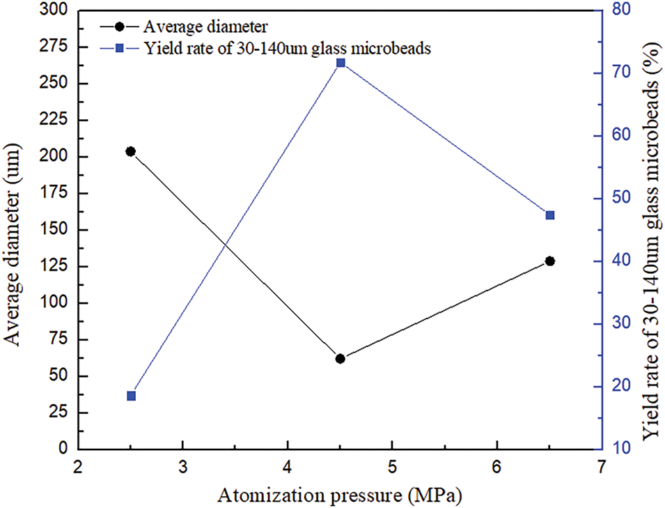
Figure 10: Average diameter and 30–140 µm yield under different atomization pressures
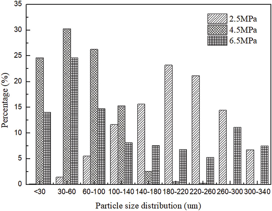
Figure 11: Particle size distribution under different atomization pressures
The close-coupled circular seam nozzle was applied in BFS granulation technology to obtain 30–140 µm slag particles and improve the utilization of BFS. This research studied atomization and the effects of atomization pressure on primary atomization and particle size. The following conclusions were drawn from this research:
(1) The gas flow field formed a recirculation zone at the bottom of the guide tube. Liquid slag was squeezed into an umbrella-shaped structure by the recirculated gas. The liquid film extending to the gas jet was broken up into droplets by high-speed airflow. The upper liquid slag continuously flowed downward and turned the umbrella-shaped structure into a cavity-shaped structure. Internal escaped gas tore the liquid around the cavity into liquid ligaments, which continued to break up into particles. Airflow velocity, recirculation zone size, and expansion waves were substantially increased with the increase of atomization pressure.
(2) Variation of guide tube outlet pressure was irregular. When atomization pressure was 4.5 MPa, guide tube outlet pressure was positive, and the umbrella-shaped structure was especially noticeable. At atomization pressure of 6.5 MPa, guide tube outlet pressure was negative, and the umbrella-shaped structure was less noticeable. The results proved that primary deformation was affected by the combined effect of airflow velocity and guide tube outlet pressure. At atomization pressure of 6.5 MPa, although airflow velocity was the fastest, the primary deformation was not substantial due to negative pressure. Primary deformation was the most apparent at 4.5 MPa.
(3) Primary atomization was better and the obtained slag particles were smaller. At a primary atomization pressure of 4.5 MPa, the average diameter was the smallest, and 30–140 µm yield was the highest. This indicated that primary atomization played a decisive role in secondary atomization.
(4) Close-coupled circular seam nozzle was applied to BFS granulation technology. When guide tube elongation was 3 mm and atomization pressure was 4.5 MPa, the average diameter was only 62 µm and 30–140 µm yield was 71.7%. This result could meet the particle size requirement for high-value-added utilization of BFS. Optical properties such as transparency, refractive index, directional reflection, and mechanical strength of the obtained slag particles were not evaluated in this research. In the future, these properties of slag particles will be further investigated, and BFS high-value-added applications, such as reflective materials, filler materials and fire-resistant coatings, will be explored.
Acknowledgement: Not applicable.
Funding Statement: This research was funded by the Tangshan University Doctor Innovation Fund (Project Number: 1402306). Li-Li Wang. received the grant.
Author Contributions: Study conception and design: Li-Li Wang; data collection: Hong-Xing Qin; analysis and interpretation of results: Li-Li Wang, Nan Dong; draft manuscript preparation: Li-Li Wang, Hong-Xing Qin, Nan Dong. All authors reviewed the results and approved the final version of the manuscript.
Availability of Data and Materials: All data and materials used to support the findings of this study are available from the corresponding author upon request.
Ethics Approval: Not applicable.
Conflicts of Interest: The authors declare no conflicts of interest to report regarding the present study.
Nomenclature
| ρ | Density |
| P | Pressure |
| t | Time |
| T | Temperature |
| Cp | Specific heat capacity at constant pressure |
| λ | Thermal conductivity |
| λt | Turbulent thermal conductivity |
References
1. Nhlanhla N, Yusuf MI. Acid leaching of blast furnace slag for enhanced zeolite synthesis. Clean Waste Syst. 2025;10(1):100207. doi:10.1016/j.clwas.2025.100207. [Google Scholar] [CrossRef]
2. Tripathy SK, Dasu J, Murthy YR, Kapure G. Utilisation perspective on water quenched and air-cooled blast furnace slags. J Clean Prod. 2020;262(2):121354. doi:10.1016/j.jclepro.2020.121354. [Google Scholar] [CrossRef]
3. Ahirwar AD, Chore HS. Experimental study of rotating dry slag granulation unit: operating regimes, particle size analysis and scale up. Appl Therm Eng. 2016;107(3):898–906. doi:10.1016/j.applthermaleng.2016.07.049. [Google Scholar] [CrossRef]
4. Saeed N, Omer B, Jama A, Dheyaaldin M. Performance of cement mortar modiffed with GGBFS at elevated temperatures with various w/b ratios and superplasticizer dosages. Constr Build Mater. 2023;368(2):130493. doi:10.1016/j.conbuildmat.2023.130493. [Google Scholar] [CrossRef]
5. Xu D, Liu JL, Du HH. Performance optimization and carbon reduction effect of solid waste-based cementitious materials from iron and steel metallurgical slags and ammonia-soda residue. Chem Eng J Adv. 2014;17:100584. doi:10.1016/j.ceja.2024.100584. [Google Scholar] [CrossRef]
6. Ding B, Wang H, Zhu X, He XY, Tan Y, Liao Q. Prediction on crystallization behaviors of blast furnace slag in a phase change cooling process with corrected optical basicity. Fuel. 2018;223:360–5. doi:10.1016/j.fuel.2018.03.038. [Google Scholar] [CrossRef]
7. Tan Y, Wang H, Zhu X. Film fragmentation mode: the most suitable way for centrifugal granulation of large flow rate molten blast slag towards high-efficiency waste heat recovery for industrialization. Appl Energy. 2020;276:115454. doi:10.1016/j.apenergy.2020.115454. [Google Scholar] [CrossRef]
8. Cooksey M, Guiraud A, Kuan Y. Design and operation of dry slag granulation pilot plant. Sustain Metal. 2020;5(2):181–94. doi:10.1007/s40831-019-00214-0. [Google Scholar] [CrossRef]
9. Peng H, Shan XK, Kang JQ. Influence of rotary disk configurations on droplets characteristics in molten slag granulation for waste heat recover. Appl Therm Eng. 2020;135:269–79. doi:10.1016/j.applthermaleng.2018.02.063. [Google Scholar] [CrossRef]
10. Peng H, Ling X, Wang DX. Experimental investigation on transition characteristics of different rotary disk configurations. Ind Eng Chem Res. 2017;56(39):11281–91. doi:10.1021/acs.iecr.7b02675. [Google Scholar] [CrossRef]
11. Tan Y, Zhu X, He XY. Granulation characteristics of molten blast furnace slag by hybrid centrifugal-air blast technique. Powder Technol. 2018;323:176–85. doi:10.1016/j.powtec.2017.09.040. [Google Scholar] [CrossRef]
12. Rajczakowska M, Alasady AM, Kothari K, Cwirzen A. Geopolymer based on mechanically activated air-cooled blast furnace slag. Materials. 2020;13(5):1134. doi:10.3390/ma13051134. [Google Scholar] [PubMed] [CrossRef]
13. Jordanov NB, Kukeva R, Stoyanovar R, Karamanov A. Sinter-crystallization kinetics and foaming of glass from metallurgical slag in air and inert atmosphere. Thermochim Acta. 2023;723(1–2):179487. doi:10.1016/j.tca.2023.179487. [Google Scholar] [CrossRef]
14. Burghardt TE, Pashkevich A, Babić D, Mosböck H, Babić D, Żakowska L. Microplastics and road markings: the role of glass beads and loss estimation. Transp Res Part D Transp Environ. 2022;102(798):103123. doi:10.1016/j.trd.2021.103123. [Google Scholar] [CrossRef]
15. Sujeong P, Gyuyong K, Byungcheol C. Characteristics on compressive strength and microstructure of high-strength cementitious composites with waste glass beads. Case Stud Constr Mater. 2023;19:e02673. doi:10.1016/j.cscm.2023.e02673. [Google Scholar] [CrossRef]
16. Pinotti VE, Andreoli AF, Gargarella P. Gas atomization of AA2017 aluminum alloy: effect of process parameters in the physical properties of powders for additive manufacturing. J Mater Res Technol. 2024;30(5):3650–62. doi:10.1016/j.jmrt.2024.04.104. [Google Scholar] [CrossRef]
17. Urionabarrenetxea E, Martín JM, Avello A, Rivas A. Simulation and validation of the gas ffow in close-coupled gas atomisation process: inffuence of the inlet gas pressure and the throat width of the supersonic gas nozzle. Powder Technol. 2022;407:117668. doi:10.1016/j.powtec.2022.117688. [Google Scholar] [CrossRef]
18. Wang P, Li J, Liu HS. Process modeling gas atomization of close-coupled ring-hole nozzle for 316 L stainless steel powder production. Chin Phys B. 2021;30(5):057502. doi:10.1088/1674-1056/abd771. [Google Scholar] [CrossRef]
19. Liu JQ, Wang P, Dong YN. Investigation on close-coupled gas atomization for Fe-based amorphous powder production via simulation and industrial trials: part I. Melt breakup behaviors during primary atomization. J Mater Res Technol. 2023;27:6568–80. doi:10.1016/j.jmrt.2023.11.124. [Google Scholar] [CrossRef]
20. Zeoli N, Tabbara H, Gu S. Three-dimensional simulation of primary break-up in a close-coupled atomizer. Appl Phys A-Mater. 2012;108(4):783–92. doi:10.1007/s00339-012-6966-7. [Google Scholar] [CrossRef]
21. Xiao F, Dianat M, McGuirk JJ. Large eddy simulation of single droplet and liquid jet primary breakup using a coupled level set/volume of fluid method. At Sprays. 2014;24(4):281–302. doi:10.1615/AtomizSpr.2014007885. [Google Scholar] [CrossRef]
22. Liu C, Li X, Shu S. Numerical investigation on flow process of liquid metals in melt delivery nozzles during gas atomization process for fine metal powder production. Trans Nonferrous Met Soc China. 2021;31(10):3192–204. doi:10.1016/S1003-6326(21)65725-4. [Google Scholar] [CrossRef]
23. Wang P, Liu JQ, Dong YN. Investigation on close-coupled gas atomization for Fe-based amorphous powder production via simulation and industrial trials: part II. Particle flight and cooling during secondary atomization. J Mater Res Technol. 2023;26:9480–9. doi:10.1016/j.jmrt.2023.09.249. [Google Scholar] [CrossRef]
24. Ünal R. The influence of the pressure formation at the tip of the melt delivery tube on tin powder size and gas/melt ratio in gas atomization method. J Mater Process Technol. 2006;180(1–3):291–5. doi:10.1016/j.jmatprotec.2006.06.018. [Google Scholar] [CrossRef]
25. Kassym K, Perveen A. Atomization processes of metal powders for 3D printing. Mater Today Proc. 2020;26(3):1727–33. doi:10.1016/j.matpr.2020.02.364. [Google Scholar] [CrossRef]
26. Nazeer YH, Ehmann M, Sami M, Gavaises M. Atomization mechanism of internally mixing twin-fluid Y-jet atomizer. J Energy Eng. 2021;147(1):04020075. doi:10.1061/(ASCE)EY.1943-7897.0000723. [Google Scholar] [CrossRef]
27. Rossano V, De Stefano G. Hybrid VOF-Lagrangian CFD modeling of droplet aero breakup. Appl Sci. 2022;12(16):8302. doi:10.3390/app12168302. [Google Scholar] [CrossRef]
28. Bhatia B, Johny T, De A. Understanding the liquid jet break-up invarious regimes at elevated pressure using a compressible VOF-LPT coupled framework. Int J Multiph Flow. 2023;159(3):104303. doi:10.1016/j.ijmultiphaseflow.2022.104303. [Google Scholar] [CrossRef]
29. Ou H, Su L, Shi Y, Ruan S. Investigation on high-viscosity chemival waste liquid atomizer based on VOF-DPM. Energies. 2023;16(7):3109. doi:10.3390/en16073109. [Google Scholar] [CrossRef]
30. Agrawal S, Wong JK, Song J, Mercan O, Kushner PJ. Assessment of the aerodynamic performance of unconventional building shapes using 3D steady RANS with SST k-ω turbulence model. J Wind Eng Ind Aerodyn. 2022;225(7):104988. doi:10.1016/j.jweia.2022.104988. [Google Scholar] [CrossRef]
Cite This Article
 Copyright © 2025 The Author(s). Published by Tech Science Press.
This work is licensed under a Creative Commons Attribution 4.0 International License , which permits unrestricted use, distribution, and reproduction in any medium, provided the original work is properly cited.
 Downloads
 Citation Tools