
 Submit a Paper
 Propose a Special lssue
 Open Access
ARTICLE

Performance of an Electro-Optic-Liquid Coupling Nozzle with a Multi-Jet Focusing Structure
School of Mechanical and Electronical Engineering, Lanzhou University of Technology, Lanzhou, 730050, China
* Corresponding Author: Xiaozong Song. Email:
Fluid Dynamics & Materials Processing 2025, 21(6), 1379-1396. https://doi.org/10.32604/fdmp.2025.061222
Received 20 November 2024; Accepted 07 March 2025; Issue published 30 June 2025
 View Full Text
 Download PDF
Abstract
Ultra-precision components have been widely used to produce advanced optoelectronic equipment. The so-called Electric field enhanced UltraViolet-Induced Jet Machining (EUV-INCJM) is an ultra-precision method that can achieve sub-nanometer level surface quality polishing. This study focuses on the application of the EUV-INCJM with different nozzle structures to a single-crystal of silicon. Two kinds of electro-optic-liquid coupling nozzles with single-jet and multi-jet focusing structures are proposed accordingly. Simulations and experiments have been conducted to verify the material removal performance of these nozzles. The simulation results show that, under the same condition, the flow velocity of the single-jet nozzle is 1.05 times higher than that achieved with the multi-jet configuration, while the current density of the latter is 1.63 times higher than that of the single-jet nozzle. For the single-crystal silicon, the material removal efficiency of the multi-jet focusing nozzle exceeds by about 1.4 times that of the single-jet. These results confirm that the material removal ability of the multi-jet configuration is more suitable for ultra-smooth surface polishing. The surface roughness of Si workpiece was reduced from Rq 1.55 to Rq 0.816 nm with valleys and peaks on its surface being almost completely removed.Keywords
Modern optoelectronic technology demands unprecedented precision in the machining accuracy and surface roughness of optoelectronic functional devices [1,2]. Minor graphic errors and surface roughness can significantly impact device performance. To ensure optimal performance, ultra-precision machining technology is required to achieve sub-nanometer machining accuracy [3,4]. Common methods for achieving ultra-smooth surfaces include chemical mechanical polishing [5–7], ion beam polishing [8], magnetorheological polishing [9,10], fluid jet polishing [11,12], elastic emission machining [13,14], and UV-INCJM [15]. In elastic emission machining and UV-INCJM, the polishing liquid is sprayed onto the workpiece surface via a nozzle [16,17]. The nozzle’s material removal characteristics are crucial for ultra-precision polishing. The removal volume must be controlled based on the discrepancy between the actual and ideal workpiece surface shapes. Consequently, the NC system determines the polishing tool’s dwell time at any point on the workpiece using the material removal function, thereby controlling the removal volume. Therefore, the removal function, efficiency, and repeatability of the polishing method influence the selection of processing paths, speed, and residence time, and determine the control characteristics for ultra-smooth surface polishing. Scholars worldwide have extensively studied jet polishing’s removal characteristics. Matsumura et al. [18] introduced a conical mask near the nozzle to alter the jet injection angle and regulate workpiece surface stress; however, the polishing surface quality did not improve significantly. Falter et al. studied the impact of polishing speed and path on stability to find the relationship between speed, step length, and surface quality [19,20]. Zhao et al. investigated the effect of abrasive diameter on material removal in liquid jet impact and found that the removed material profile changed with diameter [21]. Ma et al. designed a rotatable porous nozzle to enhance material removal and utilized it for jet polishing to achieve super-smooth surfaces [22]. Qiao et al. [23] studied jet flow distribution, removal efficiency, and nozzle functions of different structures in nano-SiO2 jet machining through simulation and experiments. Yoshinori attempted to change the removal profile shape using focused flow for a sharper flow distribution [16]. Current jet machining research primarily focuses on improving material removal efficiency and profile by modifying the nozzle structure. Array nozzles are widely employed to enhance jet polishing efficiency [24]. However, their use constitutes an external adjustment that consumes substantial additional energy. Consequently, they cannot fundamentally improve the polishing efficiency per unit power of jet polishing. UV-INCJM is an ultra-precision polishing technology capable of fabricating ultra-smooth surfaces without inducing any surface defects. A processing equipment for UV-INCJM has been developed [25]. The influences of workpiece surface micro topography on the surface material removal process have been studied [26]. UV-INCJM can be applied in the ultra-precision manufacturing of semiconductor materials. However, the photogenerated electron-hole pairs in the colloidal polishing solution are prone to recombination [27], which partially hinders the further enhancement of the material removal efficiency of UV-INCJM. To address the issue of rapid recombination of photogenerated electron-hole pairs, EUV-INCJM [28] was proposed, as illustrated in Fig. 1. Under the influence of an external electric field, photogenerated electrons are transferred to the cathode surface via an external circuit, thereby suppressing their recombination with holes. The water molecules and hydrogen ions in the colloidal polishing solution effectively capture the holes in the valence band, generating hydroxyl radicals with potent oxidizing capabilities. These radicals react with oxygen in the conduction band free electrons to produce peroxy ions with potent oxidizing capabilities [29]. As the concentration of hydroxyl radicals increases, the likelihood of the interface reaction rises, thereby enhancing the material removal efficiency.
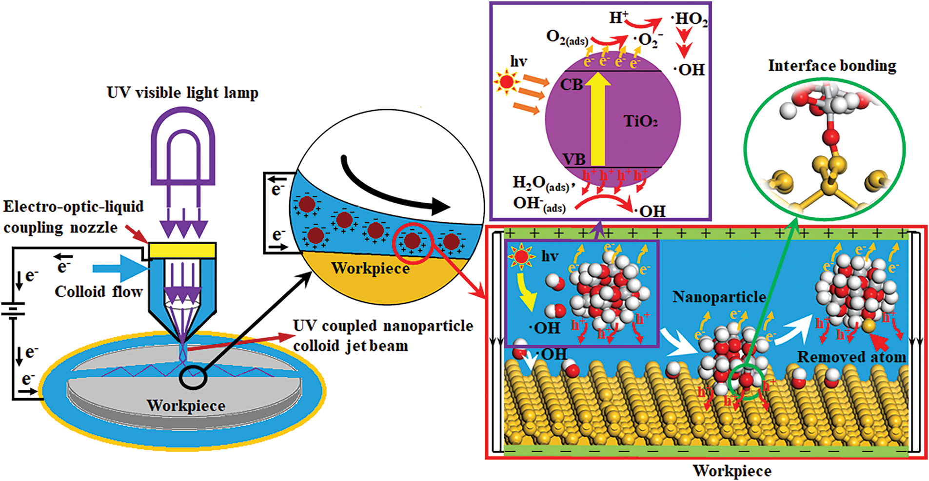
Figure 1: Schematic diagram of EUV-INCJM
In jet machining, a single-jet nozzle generates a relatively stable jet stream from a single orifice. The energy is concentrated within this single jet beam, particularly along the axis of the jet. However, as the jet disperses, the energy distribution in the radial direction becomes more diffuse. Since only one jet acts on the workpiece, the processing efficiency is relatively low, particularly for large-area processing or tasks requiring rapid material removal. In contrast, a multi-jet nozzle can produce multiple jets that act simultaneously on the workpiece surface. This allows for a larger processing area to be covered in a shorter time, significantly enhancing the material removal rate and overall processing efficiency. As a result, multi-jet nozzles are particularly well-suited for large-area material processing. However, they consume more energy compared to single-jet nozzles. During operation, the jets from a multi-jet nozzle interact with one another, creating an energy superposition and interweaving effect within a specific area. This results in a localised concentration of energy and an overall superposition envelope. Nevertheless, the mutual influence among the jets can slightly reduce the stability of the jets compared to a single-jet nozzle. By carefully designing the nozzle layout and parameters, a multi-jet nozzle can still achieve high machining accuracy. In both single-jet and multi-jet nozzle processing, the low shear velocity in the central area of the nozzle leads to reduced material removal efficiency at the nozzle centre. To address this issue and enhance the material removal efficiency within unit energy consumption, this paper proposes an electro-optic-liquid coupling nozzle with a multi-jet focusing structure. This design enables the colloidal polishing solution to pass through and focus via three focusing channel structures. The photoelectric coupling effect enhances the material removal characteristics at the nozzle centre, improving the shape of the fixed-point material removal profile in EUV-INCJM. The jets from multiple nozzles converge at specific locations, concentrating energy at the focal point to form a high-intensity jet impact zone, while the energy remains relatively weaker in other areas. The multi-jet focusing nozzle can precisely focus the jet energy on the target position, offering significant advantages for precision control of the machining position and enabling high-precision localised machining. This approach effectively reduces errors during the machining process and minimises the impact on surrounding materials. The high-energy jet at the focal point enables rapid and efficient material removal, thereby improving processing efficiency. Additionally, by leveraging the electric field to enhance material removal efficiency in the central area of the nozzle and modify the shape of the jet machining removal contour, more precise control over machining accuracy can be achieved. In this study, the material removal properties of single-crystal silicon in EUV-INCJM were investigated through three-phase fluid dynamics simulations and fixed-point polishing experiments.
The nozzle is the executing and generating device in the EUV-INCJM process. The structural characteristics of the nozzle will affect the material removal characteristics of the EUV-INCJM process. Based on the mechanism and processing requirements of EUV-INCJM, a single-jet and a multi (three)-jet focusing rectangular electro-optic-liquid coupling nozzle were designed, respectively. Fig. 2a shows the assembly diagram of the electro-optic-liquid coupling nozzle. The nozzle can be divided into upper and lower parts. These two parts are connected by fastening bolts and sealed by two seal rings. The optical fiber connector is connected from the upper part. It transmits the light into the nozzle cavity through a quartz glass window. The negative pole of the external electric field is connected with the metal electrode, and the positive pole is connected with the nozzle under the quartz glass window. When the nanoparticle colloid enters the nozzle cavity, the light field, electric field and polishing liquid flow field will be coupled in the nozzle cavity. The model of the nozzle cavity is shown in Fig. 2b. Fig. 2c shows the structures of the nozzle outlet. Here, L is the length of the nozzle outlet, W1 and W2 are the widths of the single-jet and multi-jet focusing nozzles, respectively, H is the length of the rectifier section, θ is the contraction angle of the nozzle, and α is the rectifier section angle of the multi-jet focusing nozzle. Table 1 shows the values of the above nozzle parameters. In the model of Fig. 2b, the stand-off distance is 2 mm, and the spraying angle is 90°.
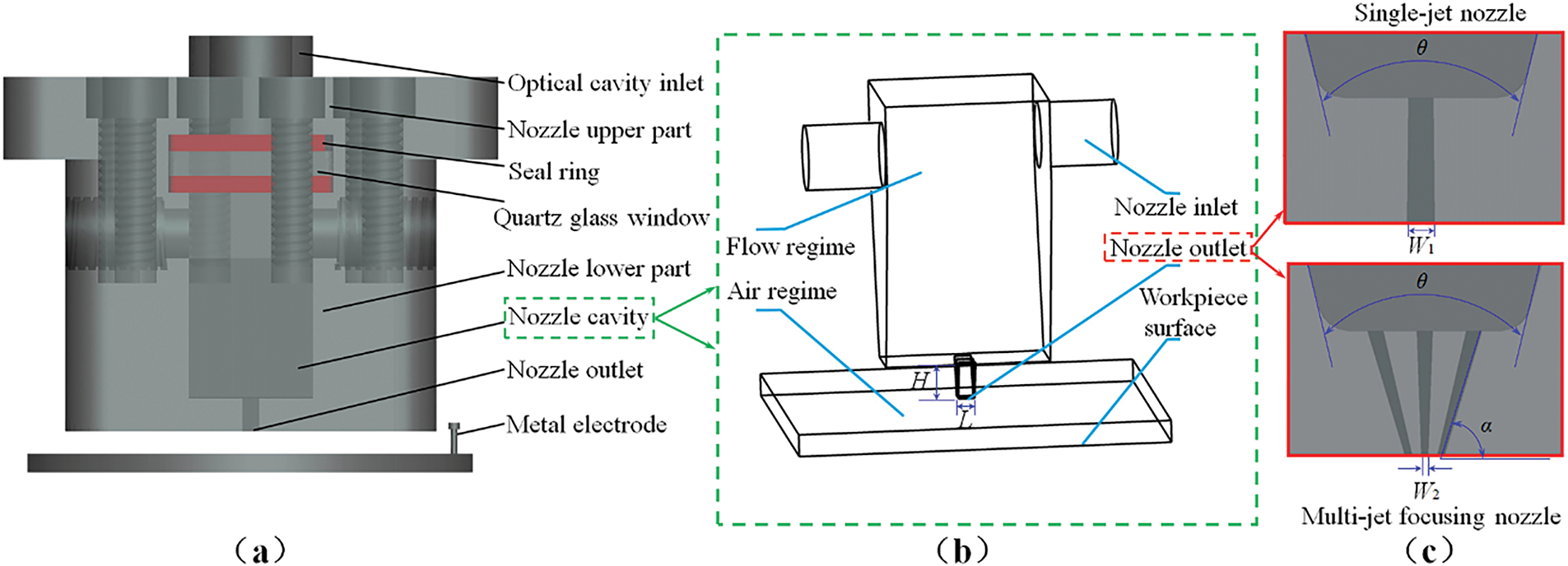
Figure 2: Diagram of the rectangular electro-optic-liquid coupling nozzle: (a) the assembly diagram, (b) the model of the nozzle chamber, (c) the structures of nozzle outlet
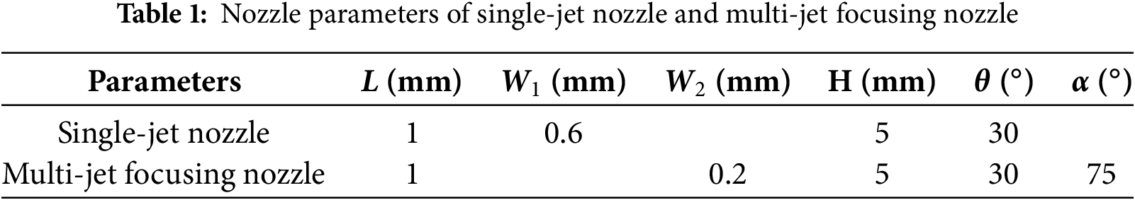
For the calculation domain of the model with regular shapes, a structured grid division is chosen. For the rectification section and nozzle inlet of the air outer and nozzle inner watersheds, the Sweet and Multi-zone methods are used to refine the grid to improve simulation accuracy. The remaining computational area is divided into unstructured grids. The number of grids after dividing the watershed is 2.45 million, as shown in Fig. 3.
Figure 3: Grid division diagram of nozzle processing watershed
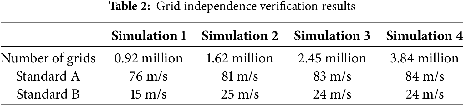
Grid independence verification was carried out. During the verification, the maximum velocity A at the outlet of the multi-jet nozzle and the maximum shear velocity B on the surface of the workpiece (near the wall) were taken as reference standards. The corresponding number of grids for different unit sizes is shown in Table 2. When the number of grids is 2.45 million, further grid refinement has little impact on the jet velocity, and the grids meet the independence requirement.
The process of EUV-INCJM is a physical process involving electric field, flow field and interaction between nanoparticles. When the concentration of nanoparticles reaches a specific level (10%), the interactions among nanoparticles must be taken into account [30,31]. However, the concentration of nanoparticles involved in this paper is extremely low. It can be assumed that the nanoparticles are uniformly dispersed in the base fluid, so the interactions among nanoparticles can be neglected. In this multiphase flow system, the coupling effects of electric field and flow field generally exists. In the simulation, the colloidal polishing slurry is assumed as an incompressible fluid [32] with stable dispersion and constant viscosity and concentration. Since the electric field used in the EUV-INCJM process is a weak electric field [33] with a voltage of 10~100 V, and the flow field is a strong flow field with a pressure of 1~10 MPa. The jet flow of polishing fluid is turbulent [34,35]. The basic governing equations (balance equations of mass, momentum and energy) in this paper are as follows:
where, ui and uj are the velocity component,
The semi-implicit method for pressure-linked equations (SIMPLE) algorithm is adopted. For the convection term, the second-order upwind scheme is used. For the transient problem, the governing equation is discretized in time using a second-order implicit scheme. The turbulent flow of nanoparticle colloid jet is described by Realizable k-ε model [36].
where,
The volume of fluid (VOF) model is utilized to simulate the flow state of the colloidal polishing slurry and air, such as the absorption, diffusion and intersection. The air is set as the main phase and the colloidal polishing solution is set as the secondary phase.
The average density of the volumetric ratio is given by the following equation:
where,
Nanoparticles are dispersed in colloidal polishing solution as discrete phase. The trajectories of nanoparticles are predicted by integrating the force balance on the nanoparticles [37]. The force balance equation of nanoparticles in polishing solution can be approximately expressed as:
where, μ is the viscosity of the fluid, dp is the nanoparticle diameter, ρ is the fluid density, ρp is the nanoparticle density, v is the fluid phase velocity, vp is the nanoparticle velocity, Fx is the additional acceleration term, and Re is the relative Reynolds number.
For the simulation of the discrete nanoparticles, the trajectories are calculated by gradually integrating over the discrete time step of Eq. (7) using discrete random walk (DRW) model [38] of stochastic tracking technique.
The electric potential method in magnetohydrodynamics model is used to simulate the distribution of the external electric field. The coupling effect between the flow field and the electric field satisfies the charge continuity equation. In the process of EUV-INCJM, the current density vector
where,
Based on the simulation, comparative verification experiments of the material removal properties of single-crystal silicon in EUV-INCJM were conducted. Fig. 4 shows the schematic diagram of the experimental equipment. It is mainly composed of three parts: the hydraulic system, the electric field enhanced photocatalysis system, and the multi degree of freedom (DOF) table. In the hydraulic system, a diaphragm pump supplies the colloidal polishing solution into the nozzle cavity.
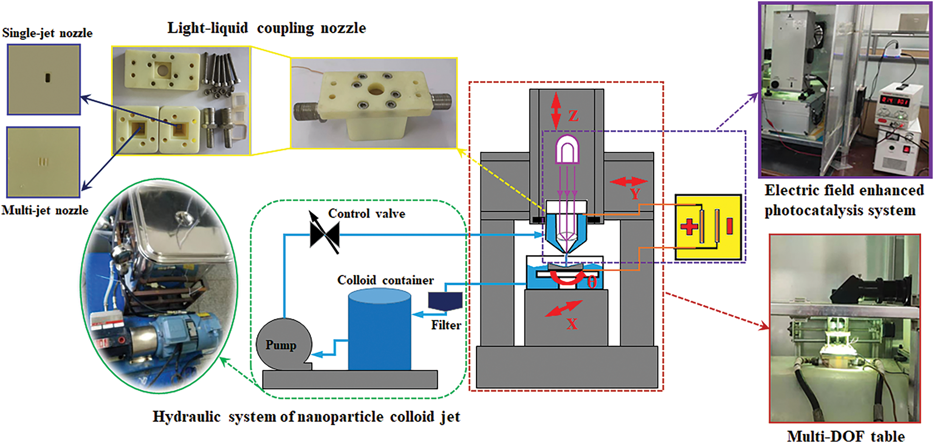
Figure 4: The equipment of EUV-INCJM
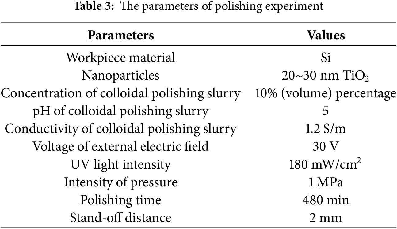
The polishing solution is composed of deionized water and TiO2 nanoparticles. Fig. 5a shows the TEM image of the TiO2 nanoparticles and Fig. 5b shows the colloidal polishing solution used in the polishing experiments. The single-crystal silicon workpiece is mounted in a tank on the set on the multi-DOF table. Polishing experiments used a single-jet nozzle and a multi-jet focusing nozzle with the same structure parameters as those in the previous fluid simulation. Table 3 shows the polishing experiment parameters.
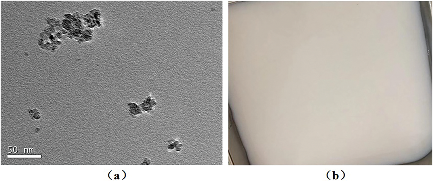
Figure 5: (a) The TEM image of the TiO2 nanoparticles, (b) the colloidal polishing solution
4.1 Jet Flow Field and Electric Field Characteristics Analysis
To study the flow field characteristics of the electro-optic-liquid coupling nozzles, fluid dynamics simulations have been performed. The velocity distributions in vertical section and on the workpiece surface (0.08 mm above the workpiece surface) are compared in Fig. 6. When the colloidal polishing solution is ejected from the nozzle outlet, the jet is not affected by the wall and can be regarded as a free jet. The velocity of the single-jet nozzle in the free jet section is 87.71 m/s, which is higher than that of the multi-jet focusing nozzle (83.18 m/s). When the colloidal polishing solution touches the workpiece surface, an impinging jet area is formed. The jet flow changes from axial flow to radial flow, and the flow velocity decreases to about one-third of that in the free jet section. As the polishing solution continues to flow on the workpiece surface, the flow velocity continues to weaken, and the flow becomes relatively stable, forming a wall jet area. The velocity distribution center of the single-jet nozzle is sharper, while that of the multi-jet focusing nozzle is flatter. Turbulence intensity is a key parameter of fluid in complex turbulent motion. It reflects the relative intensity of velocity. The turbulence intensity distributions of the two nozzles are shown in Fig. 7. The change of turbulence intensity in the flow field mainly occurs in the rectification section and the impinging jet area. In the rectifying section, the turbulence intensity of the jet beam is significantly lower at the axis than on the adjacent two sides. This is more evident in the flow field of the single-jet nozzle. The maximum turbulence intensity appears in a section near the axis. This is because as the jet distance increases, the intensity of energy alternation between the boundary layer of the jet beam and the surrounding medium rises. Also, the polishing solution continuously diffuses, causing the turbulence intensity to increase. The turbulence intensity has a maximum value in the impinging jet area. It is 16.72 for the single-jet nozzle and 16.64 for the multi-jet focusing nozzle. When the polishing solution impacts the workpiece surface, the movement direction of the polishing solution changes. The jet beam then flows parallel to the workpiece surface, leading to a weakening of the turbulence intensity on the workpiece surface. The turbulence intensity of the single-jet nozzle is greater than that of the multi-jet focusing nozzle. The turbulence intensity distribution area of the single-jet nozzle is also large and irregular. This indicates that the distribution of the colloidal polishing solution from the single-jet nozzle on the workpiece surface is unstable, and is not conducive to the uniform material removal of the workpiece surface.
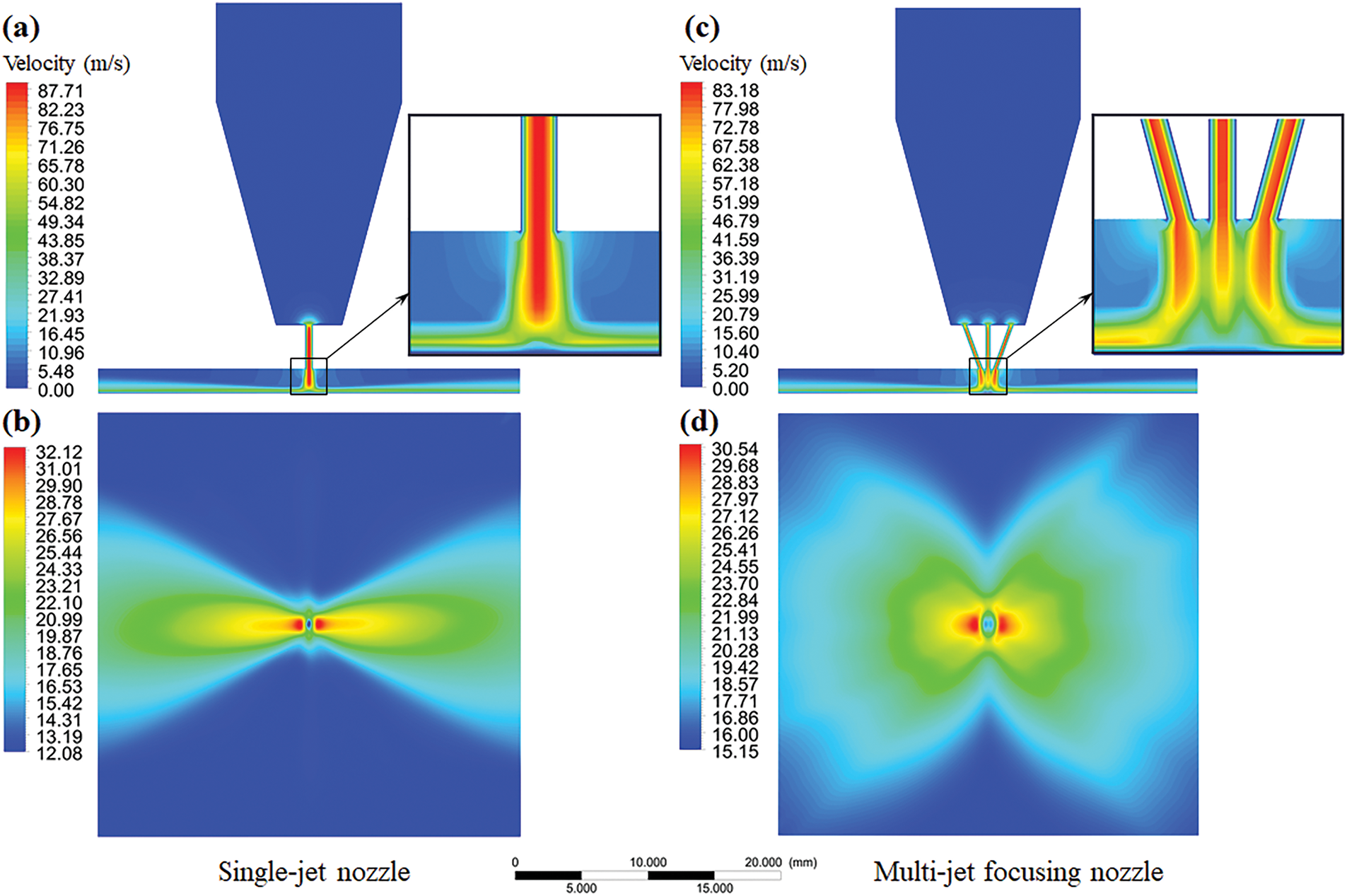
Figure 6: (a) Velocity of jet flow in vertical section of the single-jet nozzle, (b) velocity of jet flow on the workpiece surface of the single-jet nozzle, (c) velocity of jet flow in vertical section of the multi-jet focusing nozzle and (d) velocity of jet flow on the workpiece surface of the multi-jet focusing nozzle
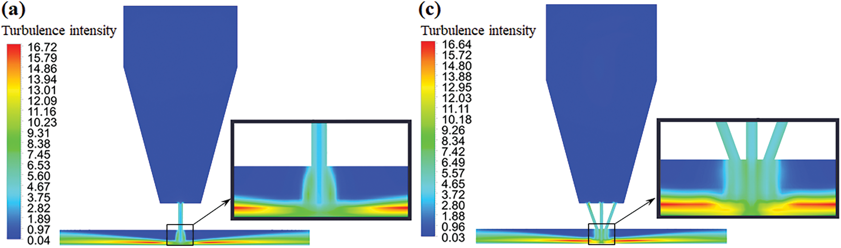
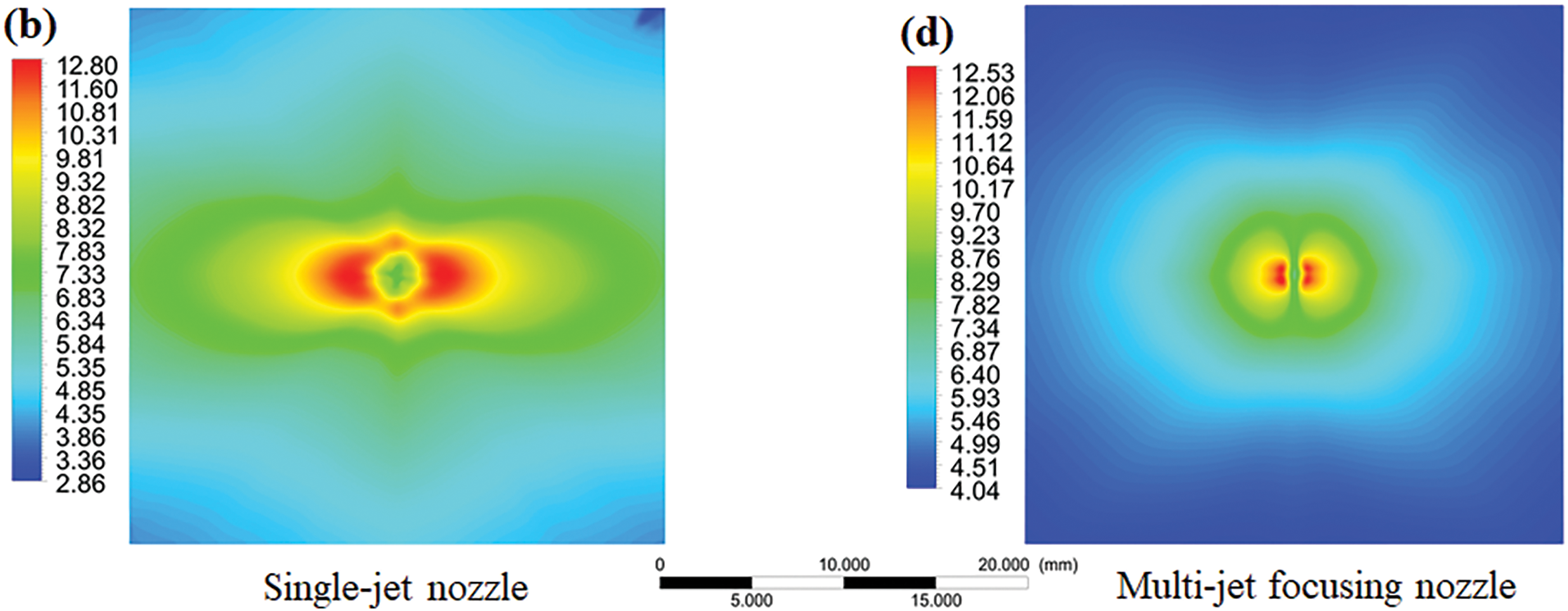
Figure 7: (a) Turbulence intensity of jet flow in vertical section of the single-jet nozzle, (b) turbulence intensity of jet flow on the workpiece surface of the single-jet nozzle, (c) turbulence intensity of jet flow in vertical section of the multi-jet focusing nozzle and (d) turbulence intensity of jet flow on the workpiece surface of the multi-jet focusing nozzle
In the process of EUV-INCJM, the movement of nanoparticles in the flow field affects the material removal of the workpiece. The floating track and residence time of nanoparticles during EUV-INCJM are shown in Fig. 8. As the inlets of the electro-optic-liquid coupling nozzle are asymmetrically biased, the nanoparticles form eddy currents in the nozzle cavity with the movement of the polishing solution, and then quickly pass through the rectification section of the nozzle in a straight line. Then the nanoparticles follow the colloidal polishing solution to impact the workpiece surface and spread rapidly around. The floating track of the nanoparticles from the single-jet nozzle shows a partially concentrated distribution pattern. In contrast, the floating track of the nanoparticles in the multi-jet focusing nozzle is uniformly distributed. In this process, the maximum residence time of nanoparticles in the single-jet nozzle is 0.35 s, while in the multi-jet focusing nozzle it is 0.26 s.
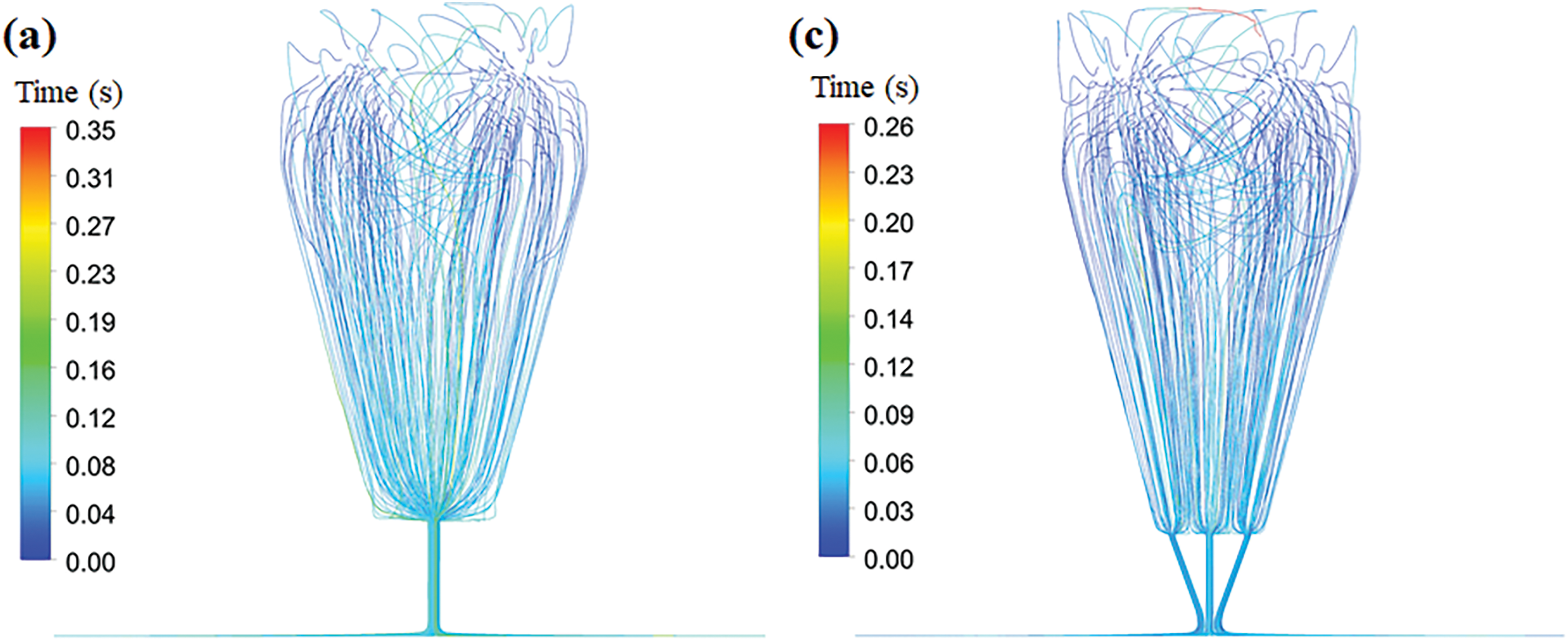
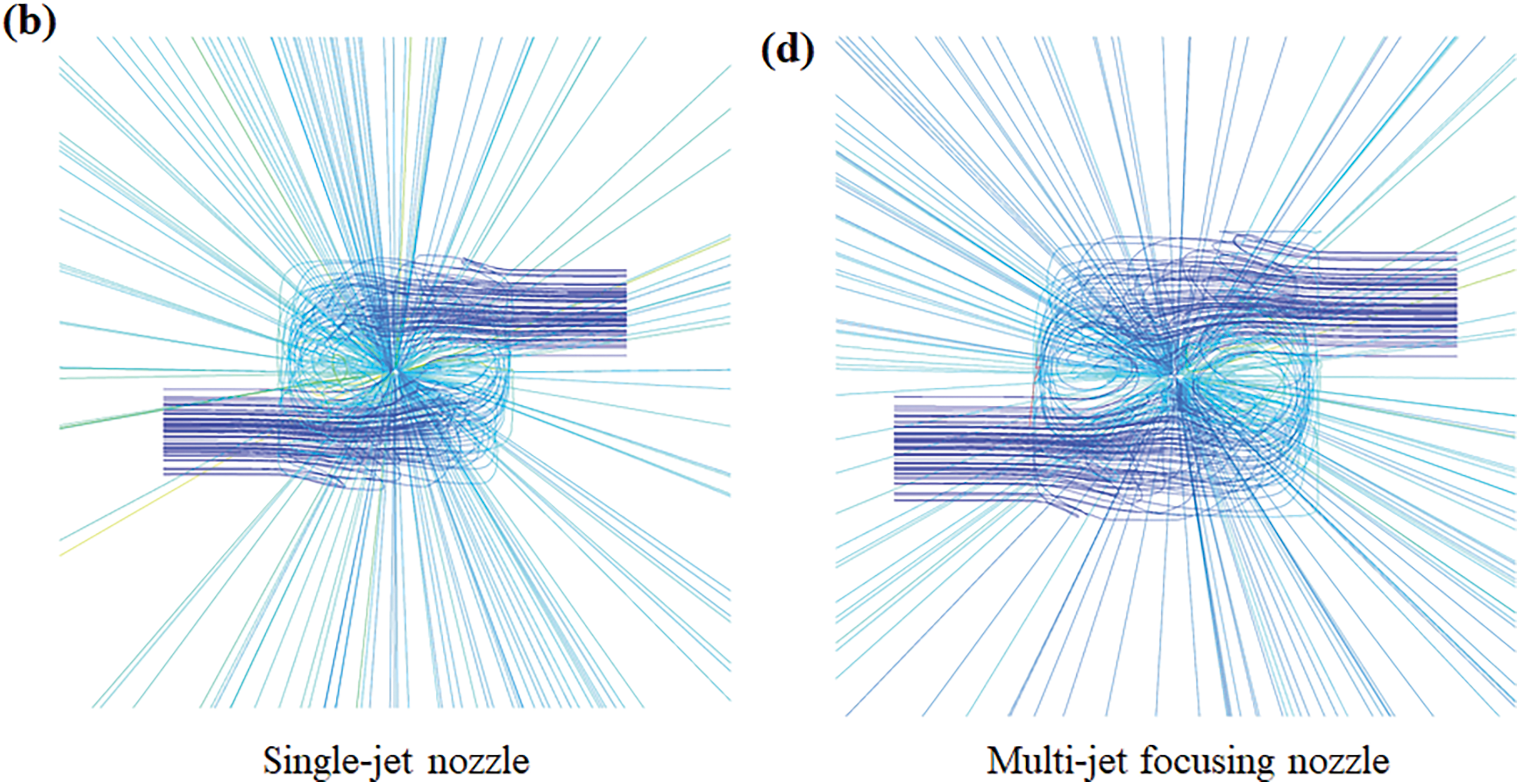
Figure 8: Floating track and residence time of nanoparticles in the jet flow: (a) front view and (b) top view of the single-jet nozzle, (c) front view and (d) top view of the multi-jet focusing nozzle
In EUV-INCJM, the applied electric field generates a directional electric current between the workpiece surface and the nozzle outlet. The current density distributions of the two nozzles are shown in Fig. 9. In the vertical section, the maximum current density in the nozzle cavity is located in the rectifier section of the nozzle. The maximum current density of single-jet nozzle is 6.6 × 10⁴ A/m2, and that of the multi-jet focusing nozzle is 6.31 × 10⁴ A/m2. As shown in Fig. 9c,d, the patterns of the current density of the single-jet nozzle and the multi-jet focusing nozzle are similar. The current density is strongest in the center of the jet, and gradually decreases toward the circle. However, the current density distribution area of multi-jet focusing nozzle is obviously higher than that of the single-jet nozzle. The maximum value of the current density for the multi-jet focusing nozzle is 6.55 × 10³ A/m2, significantly higher than that of 4.01 × 10³ A/m2 for the single-jet nozzle.
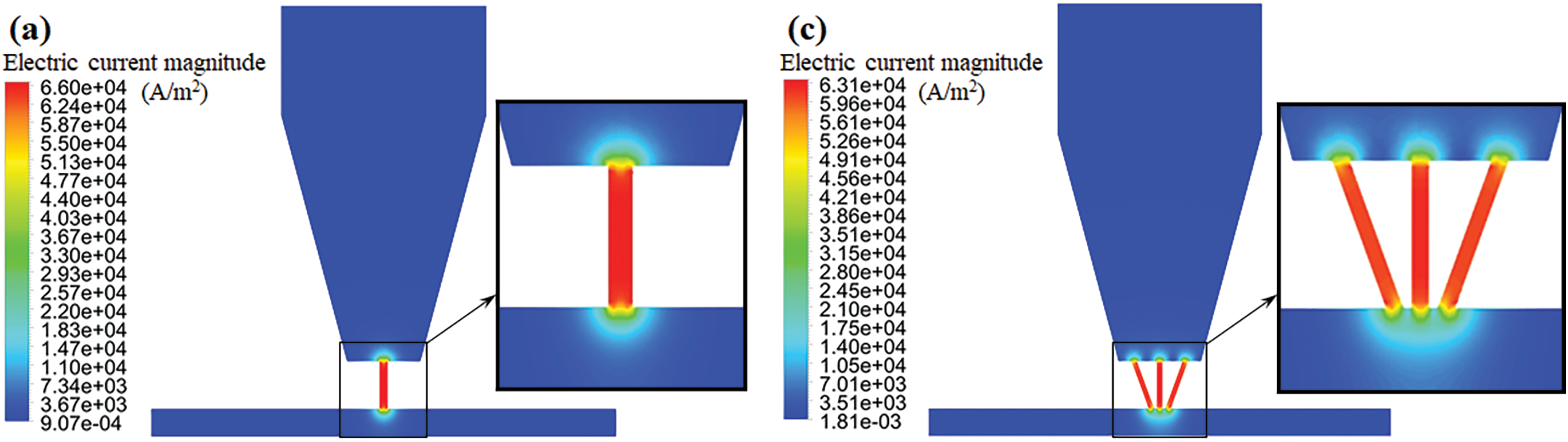
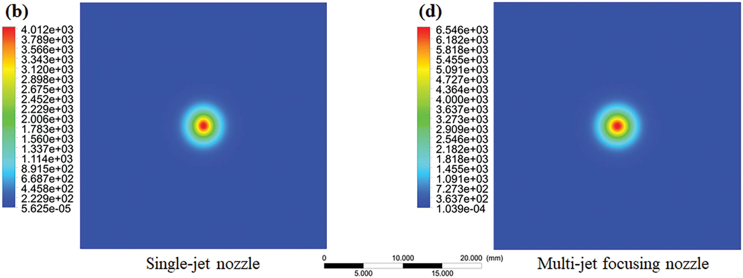
Figure 9: Current density distribution of jet flow: (a) in vertical section and (b) on the workpiece surface of the single-jet nozzle, (c) in vertical section and (d) on the workpiece surface of the multi-jet focusing nozzle
4.2 Experimental Study on Material Removal Efficiency
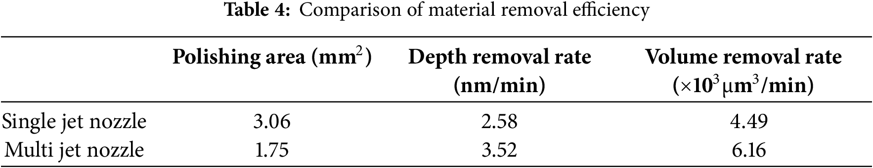
To verify the polishing performance and material removal characteristics of single-crystal silicon in EUV-INCJM, two fixed points were machined on a silicon workpiece with two types of nozzles respectively. The profiles of the fixed points were detected and the surface micro morphology were shown in Fig. 10. For the workpiece surface processed by the single-jet nozzle, the position with the most material removed is not in the jet center region. Instead, it is distributed in a square ring. The shape of the material removal is similar to a “W” shape in both vertical and horizontal directions, with the center high and the surrounding low. The maximum removal depth of the workpiece surface processed by single-jet nozzle is 1.24 μm. For the workpiece surface processed by the multi-jet nozzle, the position with the most material removed is in the jet center region. The removal shape is approximately rectangular, and the surface removal depth is uniform. The maximum removal depth of the surface is 1.69 μm. Table 4 shows the comparison results of material removal efficiency of two nozzles. According to the comparison results in Table 4, the polishing area of the single-jet nozzle is approximately 1.75 times larger than that of the multi-jet nozzle. Meanwhile, the removal efficiency of the multi-jet nozzle is about 1.36 times higher than that of the single-jet nozzle.
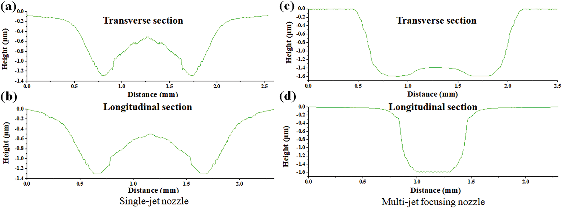
Figure 10: The corrected material removal profile: (a) transverse section and (b) longitudinal section of single-jet nozzle, (c) transverse section and (d) longitudinal section of multi-jet focusing nozzle
There are significant differences between the material removal shapes of the single-jet nozzle and the multi-jet focusing nozzle. The reason for this difference lies in the different flow fields and electric field distributions on the workpiece surface during the machining processes of the two nozzles. The electro-optic-liquid coupling nozzle has the maximum current density at the center of the vertical jet zone because of the external electric field. Photogenerated electron-hole pairs are efficiently separated under the action of the electric field. This avoids their rapid recombination in the colloid jet beam and greatly enhances the photocatalytic effect. Therefore, the photocatalytic effect has a substantial influence on the material removal efficiency in EUV-INCJM. It greatly increases the probability of reaction and improves the material removal efficiency at the center of the jet.
To intuitively demonstrate the promoting effect of the electric field on the adsorption of TiO2 nanoparticles on the Si workpiece through experiments, an adsorption experiment was carried out. With and without an applied external electric field, a single-crystal silicon substrate was processed by UV-INCJM for 3 min. Fig. 11a shows the SEM image of the original workpiece, which is clean and free from pollution. Fig. 11b,c shows the SEM images of the single-crystal silicon substrate processed by EUV-INCJM under the external field voltage of 0 and 30 V, respectively. There are TiO2 nanoparticles adsorbed on the processed workpiece surface. When the applied electric field is 30 V, the number of TiO2 nanoparticles adsorbed on the processed workpiece surface is much larger than that of 0 V. The comparison results show that the external electric field promotes the adsorption of the TiO2 nanoparticles on the Si workpiece surface.
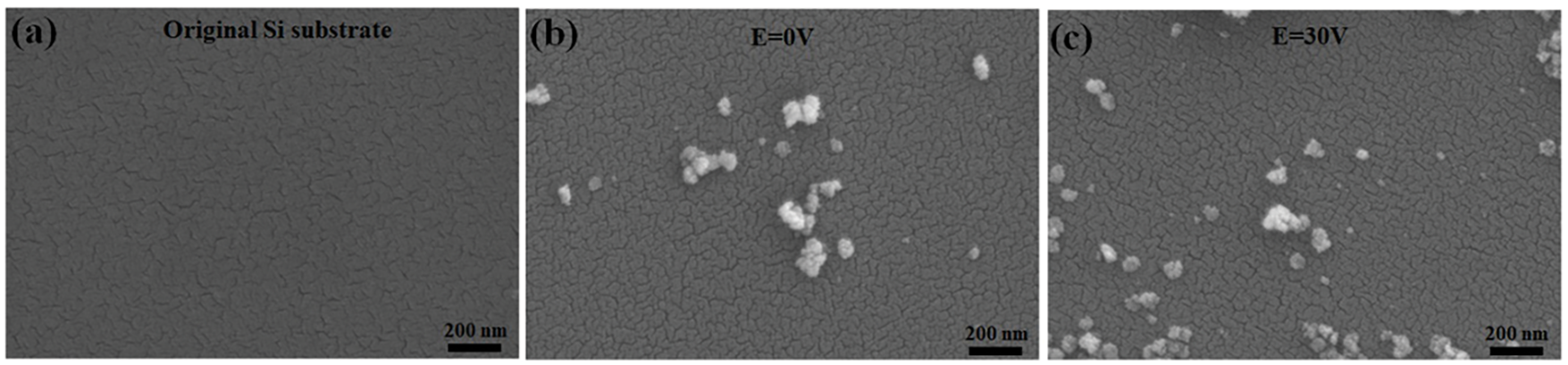
Figure 11: The SEM images of the Si workpiece before and after processed by EUV-INCJM with different voltage for 3 min: (a) the original Si workpiece, (b) 0 V, (c) 30 V
4.3 Experimental Study on Surface Polishing Quality
To evaluate the surface roughness of the single-crystal silicon workpiece processed by EUV-INCJM with single-jet and multi-jet focusing nozzles, atomic force microscope (AFM) was used to analyze the micro morphology and surface roughness before and after polishing. The measured surface micromorphology and roughness results are shown in Fig. 12. The surface of the original single-crystal silicon workpiece is generally uneven, with many continuous burrs and scratches, and some randomly distributed pits. Before processing, the surface roughness of Ra and Rq of the original silicon workpiece were 0.901 and 1.55 nm. The cross section analysis results show that there are many peaks and valleys on the original silicon workpiece surface, with a height of ±10 nm. After polishing by the single-jet nozzle, the burrs and scratches on the silicon workpiece were basically removed. The height of the surface peaks and valleys were reduced to about ±5 nm. The surface roughness of Ra and Rq of the workpiece were reduced to 0.955 and 1.28 nm. The scratches and pits on the Si workpiece surface polished by the multi-jet focusing nozzle were completely removed. The overall surface morphology was significantly improved, the height of the surface peaks and valleys were reduced to about ±2 nm. The surface roughness of Ra and Rq were reduced to 0.647 and 0.816 nm.
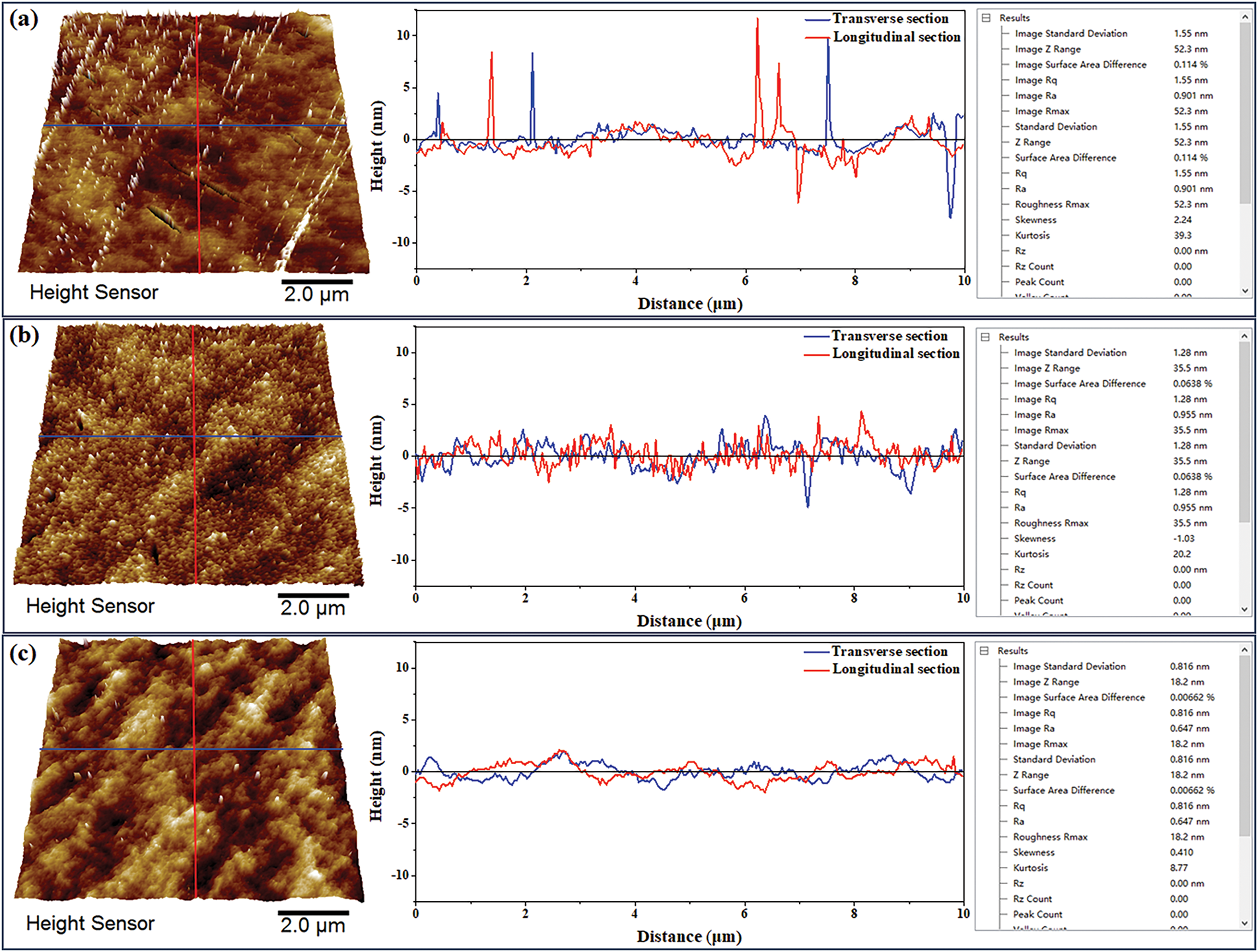
Figure 12: The surface morphology and surface roughness of silicon workpieces (a) the original Si workpiece, (b) polished by single-jet nozzle, (c) polished by multi-jet focusing nozzle
The above three Si workpieces before and after EUV-INCJM were evaluated by PSD [39,40] to judge the surface quality as shown in Fig. 13. In the wavelength range of 0.07–10 μm, the PSD value of the workpiece polished by the single-jet nozzle decreased slightly compared to the workpiece before polishing. However, the PSD value of the workpiece polished by the multi-jet focusing nozzle decreased significantly. The results show that the surface quality has been improved more significantly after being polished by the multi-jet focusing nozzle.
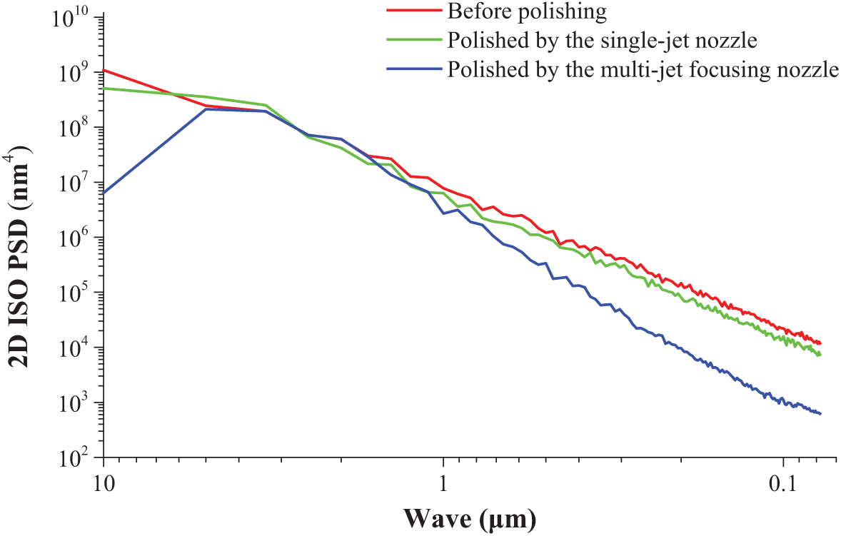
Figure 13: The PSD of the Si workpieces
This paper presents the material removal characteristics of single-crystal silicon using the electro-optic-liquid coupling nozzle with single-jet and multi-jet focusing structures in EUV-INCJM. The flow field and electric field distributions are simulated and the material removal efficiency are investigated experimentally.
1. Under the same pressure, the flow velocity of the multi-jet focusing nozzle is comparable to that of the single-jet nozzle. However, the flow field distribution of the multi-jet focusing nozzle is more uniform and stable, with lower turbulence intensity and scattering degree. The residence time of nanoparticles in the multi-jet focusing nozzle is about 0.7 times shorter than that in the single jet nozzle. The current density on the workpiece surface of the multi-jet focusing nozzle is about 1.6 times higher than that of the single-jet nozzle.
2. The processing area of the multi-jet focusing nozzle is about 0.6 times less than that of the single-jet nozzle, and its material removal efficiency is about 1.4 times higher than that of the single-jet nozzle. The material removal profile of the single-jet nozzle is “W” shaped, while that of the multi-jet focusing nozzle is “U” shaped.
3. The auxiliary effect of the electric field is more obvious in the polishing process of the multi-jet focusing nozzle. The surface roughness of the workpiece polished by the multi-jet focusing nozzle is lower and the surface quality is higher. The multi-jet focusing nozzle can achieve ultra-smooth surface polishing more quickly. An ultra-smooth surface of Si workpiece with surface roughness of Ra 0.647 nm (Rq0.816 nm) has been created by the multi-jet focusing nozzle.
4. The structural design and material removal performance verification of the multi-jet focusing nozzle in EUV-INCJM was preliminarily carried out in this article. However, the structural optimization and process optimization still need to be further studied in future work in order to obtain better removal characteristics and be practically applied in industrial processing.
Acknowledgement: Not applicable.
Funding Statement: This work was financially supported by the National Natural Science Foundation of China (52365056).
Author Contributions: The authors confirm contribution to the paper as follows: Conceived idea and wrote the paper: Xiaozong Song; Developed the theory and provided corrections: Xiaozong Song and Jiangbin Liu; Performed the experiments: Longhua Fei; Analyzed the experiment results: Wencong Zhang. All authors reviewed the results and approved the final version of the manuscript.
Availability of Data and Materials: All data that support the findings of this study are included in the article.
Ethics Approval: Not applicable.
Conflicts of Interest: The authors declare no conflicts of interest to report regarding the present study.
References
1. Bond C, Brown D, Freise A, Strain KA. Interferometer techniques for gravitational-wave detection. Living Rev Relativ. 2016;19:3. doi:10.1007/s41114-016-0002-8. [Google Scholar] [PubMed] [CrossRef]
2. Fortmeier I, Schachtschneider R, Ledl V, Matousek O, Siepmann J, Harsch A, et al. Round robin comparison study on the form measurement of optical freeform surfaces. J Eur Opt Soc-Rapid Publ. 2020;16:2. doi:10.1186/s41476-019-0124-1. [Google Scholar] [CrossRef]
3. Tan Z, Jiang X, Mao Y, Long X, Luo H. Ultra-smooth surface with 0.4 Å roughness on fused silica. Ceram Int. 2023;49(5):7245–51. doi:10.1016/j.ceramint.2022.08.022. [Google Scholar] [CrossRef]
4. Bouillet S, Ameil C, Beau V, Bonville O, Cavaro S, Courchinoux R, et al. Large optics metrology for high-power lasers. J Opt Soc Am A. 2019;36(11):C95. doi:10.1364/josaa.36.000c95. [Google Scholar] [PubMed] [CrossRef]
5. Liao ME, Huynh K, Matto L, Luccioni DP, Goorsky MS. Optimization of chemical mechanical polishing of (010) β-Ga2O3. J Vac Sci Technol A. 2023;41(1):013205. doi:10.1116/6.0002241. [Google Scholar] [CrossRef]
6. Islam MS, Jung GY, Ha T, Stewart DR, Chen Y, Wang SY, et al. Ultra-smooth platinum surfaces for nanoscale devices fabricated using chemical mechanical polishing. Appl Phys A. 2005;80:1385–9. doi:10.1007/s00339-004-3170-4. [Google Scholar] [CrossRef]
7. Ryu HJ, Kim DG, Kang S, Jeong JH, Kim S. Mechanical abrasion by bi-layered pad micro-asperity in chemical mechanical polishing. CIRP Ann. 2021;70(1):273–6. doi:10.1016/j.cirp.2021.04.012. [Google Scholar] [CrossRef]
8. Lunin LS, Sinel’nikov BM, Sysoev IA. Features of ion-beam polishing of the surface of sapphire. J Synch Investig. 2018;12(5):898–901. doi:10.1134/S1027451018050105. [Google Scholar] [CrossRef]
9. Belov DV, Belyaev SN, Malshakova OA, Sorokoletova NA, Serebrov EI. Preparation of nanoabrasive for magnetorheological polishing of KDP crystals. Colloid J. 2024;86(4):505–18. doi:10.1134/S1061933X24600477. [Google Scholar] [CrossRef]
10. Kumar M, Das M. Impact of different magnetorheological fluid compositions on poppet valve profile polishing. Precis Eng. 2022;76:75–87. doi:10.1016/j.precisioneng.2022.03.002. [Google Scholar] [CrossRef]
11. Anbarasu KG, Vijayaraghavan L, Arunachalam N. Experimental study on surface generation in optical glass with fluid jet polishing process. Int J Abras Technol. 2018;8(3):245–60. doi:10.1504/ijat.2018.10015439. [Google Scholar] [CrossRef]
12. Saha A, Dhamanekar A, Arunachalam N, Diwakar SV. Numerical simulations of an acoustophoresis-assisted fluid jet polishing process. J Manuf Process. 2025;134:1034–56. doi:10.1016/j.jmapro.2024.12.052. [Google Scholar] [CrossRef]
13. Yamauchi K, Mimura H, Inagaki K, Mori Y. Figuring with subnanometer-level accuracy by numerically controlled elastic emission machining. Rev Sci Instrum. 2002;73(11):4028–33. doi:10.1063/1.1510573. [Google Scholar] [CrossRef]
14. Kanaoka M, Liu C, Nomura K, Ando M, Takino H, Fukuda Y, et al. Figuring and smoothing capabilities of elastic emission machining for low-thermal-expansion glass optics. J Vac Sci Technol B. 2007;25(6):2110–3. doi:10.1116/1.2789440. [Google Scholar] [CrossRef]
15. Song XZ, Gao G, Zhou YX, Gong J, Wang HG. Adsorption of TiO2 nanoparticles on monocrystalline silicon surface. Opt Precis Eng. 2016;24:1694–702. doi:10.3788/OPE.20162407.1694. [Google Scholar] [CrossRef]
16. Takei Y, Mimura H. Effect of focusing flow on stationary spot machining properties in elastic emission machining. Nanoscale Res Lett. 2013;8:237. doi:10.1186/1556-276X-8-237. [Google Scholar] [PubMed] [CrossRef]
17. Song XZ, Tong Y. Effect of nozzle cavity on polishing ability of light coupled colloid jet. Opt Precis Eng. 2019;27(9):2011–9. doi:10.3788/ope.20192709.2011. [Google Scholar] [CrossRef]
18. Matsumura T, Muramatsu T, Fueki S. Abrasive water jet machining of glass with stagnation effect. CIRP Ann-Manuf Technol. 2011;60(1):355–8. doi:10.1016/j.cirp.2011.03.118. [Google Scholar] [CrossRef]
19. Falter M, Schinhaerl M, Rascher R, Wünsche C. Roughness improvement in active fluid jet polishing (A-FJP) by optimization of the polishing pin. In: Proceedings of SPIE—The International Society for Optical Engineering; 2013 May 13–14; Munich, Germany. p. 8838. doi:10.1117/12.2023007. [Google Scholar] [CrossRef]
20. Maurer R, Biskup H, Trum C, Rascher R, Christine W. Determination of a suitable parameter field for the active fluid jet polishing process. In: Proceedings of SPIE—The International Society for Optical Engineering; 2013 May 13–14; Munich, Germany. p. 8884. doi:10.1117/12.2028752. [Google Scholar] [CrossRef]
21. Zhao X, Ma L, Xu X. Mode transition from adsorption removal to bombardment removal induced by nanoparticle-surface collisions in fluid jet polishing. Friction. 2021;9(5):1127–37. doi:10.1007/s40544-020-0408-x. [Google Scholar] [CrossRef]
22. Ma ZL, Liu J, Wang JL. Material removal mechanism and influence factor of fluid jet polishing. J Appl Opt. 2011;32(6):1206–11. doi:10.1016/B978-0-444-53599-3.10005-8. [Google Scholar] [CrossRef]
23. Qiao S, Shi F, Tian Y, Jiao ZY, Yang P, Zhang WL. Numerical and experimental investigations on NANO-SIO2 jet polishing efficiency by different nozzle structures. Ceram Int. 2022;48:15603–12. doi:10.1016/j.ceramint.2022.02.094. [Google Scholar] [CrossRef]
24. Wang CJ, Cheung CF, Ho LT, Liu MY, Lee WB. A novel multi-jet polishing process and tool for high-efficiency polishing. Int J Mach Tools Manuf. 2017;115:60–73. doi:10.1016/j.ijmachtools.2016.12.006. [Google Scholar] [CrossRef]
25. Song XZ, Gao G. Removal mechanism investigation of ultraviolet induced nanoparticle colloid jet machining. Molecules. 2021;26(1):68. doi:10.3390/molecules26010068. [Google Scholar] [PubMed] [CrossRef]
26. Song XZ, Niu YJ, Gao G. Effects of surface microtopography on material removal and ultra-smooth surface creation processes in ultraviolet-induced nanoparticle colloid jet machining. Colloids Surf A: Physicochem Eng Asp. 2022;648:129161. doi:10.1016/j.colsurfa.2022.129161. [Google Scholar] [CrossRef]
27. Zhang Z, Yates JT Jr. Direct observation of surface-mediated electron-hole pair recombination in TiO2(110). J Phys Chem C. 2010;114(7):3098–101. doi:10.1021/jp910404e. [Google Scholar] [CrossRef]
28. Song XZ, Ge SD, Niu YJ, Yan DW. Effect of external electric field on ultraviolet-induced nanoparticle colloid jet machining. Nanotechnol. 2022;33(21):215302. doi:10.1088/1361-6528/ac55d0. [Google Scholar] [PubMed] [CrossRef]
29. Augugliaro V, Yurdakal S, Loddo V, Palmisano G, Palmisano L. Determination of photoadsorption capacity of polychrystalline TiO2 catalyst in irradiated slurry. Adv Chem Eng. 2009;36:1–35. doi:10.1016/S0065-2377(09)00401-3. [Google Scholar] [CrossRef]
30. Abbasi A, Gharsi S, Dinarvand S. A review of the applications of nanofluids and related hybrid variants in flat tube car radiators. Fluid Dyn Mater Process. 2025;21(1):37–60. doi:10.32604/fdmp.2024.057545. [Google Scholar] [CrossRef]
31. Mahmoud EM, Abdelowahed H, Khadija C. Modeling thermophysical properties of hybrid nanofluids: foundational research for future photovoltaic thermal applications. Fluid Dyn Mater Process. 2025;21(1):61–70. doi:10.32604/fdmp.2024.053458. [Google Scholar] [CrossRef]
32. Hureau J, Weber R. Impinging free jets of ideal fluid. J Fluid Mech. 1998;372:357–74. doi:10.1017/s002211209800247x. [Google Scholar] [CrossRef]
33. Ganchenko G, Frants E, Shelistov V, Demekhin E. The movement of an ion-exchange microparticle in a weak external electric field. Microgravity Sci Technol. 2018;30(4):411–7. doi:10.1007/s12217-018-9627-4. [Google Scholar] [CrossRef]
34. Gaifullin AM, Shcheglov AS. Flow structure of a three-dimensional turbulent wall jet. Fluid Dyn. 2023;58(7):1266–76. doi:10.1134/S0015462823602115. [Google Scholar] [CrossRef]
35. Balachandar S, Eaton JK. Turbulent dispersed multiphase flow. Annu Rev Fluid Mech. 2010;42:111–33. doi:10.1146/annurev.fluid.010908.165243. [Google Scholar] [CrossRef]
36. Shih T, Liou WW, Shabbir A, Yang Z, Zhu J. A new k-εeddy viscosity model for high Reynolds number turbulent flows: model development and validation. Comput Fluid. 1995;24(3):227–38. doi:10.1016/0045-7930(94)00032-T. [Google Scholar] [CrossRef]
37. Mansouri A, Arabnejad H, Shirazi SA, McLaury BS. A combined CFD/experimental methodologyfor erosion prediction. Wear. 2015;332–3:1090–7. doi:10.1016/j.wear.2014.11.025. [Google Scholar] [CrossRef]
38. Gosman AD, Loannides E. Aspects of computer simulation of liquid-fueled combustors. AIAA J. 1981;81:482–90. doi:10.2514/6.1981-323. [Google Scholar] [CrossRef]
39. Li Q, Deng Y, Li J, Shi W. Roughness characterization and formation mechanism of abrasive air jet micromachining surface studied by power spectral density. J Manuf Process. 2020;57:737–47. doi:10.1016/j.jmapro.2020.07.039. [Google Scholar] [CrossRef]
40. Krolczyk GM, Maruda RW, Nieslony P, Wieczorowski M. Surface morphology analysis of Duplex Stainless Steel (DSS) in clean production using the power spectral density. Measurement. 2016;94:464–70. doi:10.1016/j.measurement.2016.08.023. [Google Scholar] [CrossRef]
Cite This Article
 Copyright © 2025 The Author(s). Published by Tech Science Press.
This work is licensed under a Creative Commons Attribution 4.0 International License , which permits unrestricted use, distribution, and reproduction in any medium, provided the original work is properly cited.
 Downloads
 Citation Tools