
 Submit a Paper
 Propose a Special lssue
 Open Access
REVIEW

An Overview of Drag Reduction Methods in Road Cars
1 Independent Researcher, Brescia, Italy
2 Department of Engineering and Applied Sciences, University of Bergamo, Dalmine, Italy
* Corresponding Author: Silvia Ravelli. Email:
Fluid Dynamics & Materials Processing 2026, 22(2), 1 https://doi.org/10.32604/fdmp.2026.075225
Received 27 October 2025; Accepted 03 February 2026; Issue published 04 March 2026
 View Full Text
 Download PDF
Abstract
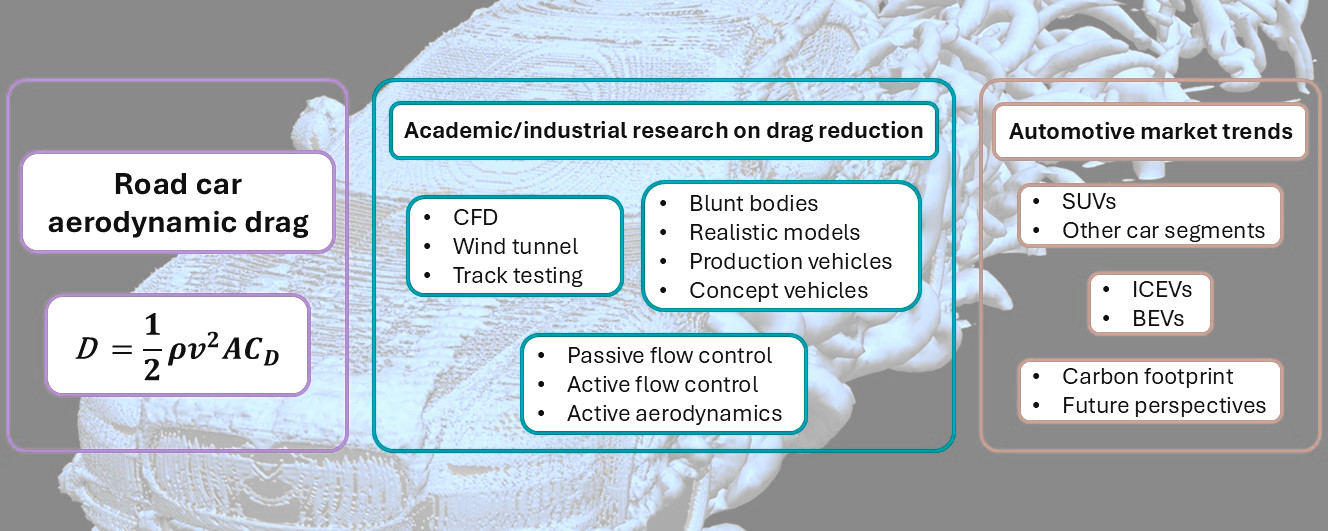
Aerodynamic research on road cars was reviewed in this work under the thread of reducing drag, with the awareness that this may succeed in effectively decreasing the carbon footprint of transportation. First, a selection of studies was presented to focus on the most important aerodynamic features of the flow around realistic car body shapes. Then, the discussion was organized around three pillars related to passive flow control, active flow control and active aerodynamics. Both experimental and numerical investigations were included to provide a comprehensive overview. A clear distinction was made between simplified and realistic car models, as well as production vehicles (within the limits of restricted access information). Moreover, a short essay was dedicated to electric vehicles, for which aerodynamics matters, especially at highway speeds. Last, the impact of aerodynamic principles on the design of current and future vehicle fleet was assessed, honestly admitting that recent market trends must be reversed to turn decarbonization goals into reality and damp the effects of global warming.Graphic Abstract
Keywords
In all fields of science, reviews should be carried out to address a clearly-stated question. In this case, the question is “How to make a road car more efficient and reduce CO2 emissions?” Although most of the attention is paid to how cars are and will be powered, engine alone is not enough to lessen their environmental impact. In this review, the focus is on aerodynamic aspects, with emphasis on academic and industrial efforts to reduce drag, improving efficiency and thus fuel economy. The present study has been conceived as a summary of the methods used to evaluate and validate drag in a passenger car, without entering into the high-level of detail required to explain the fluid-dynamic mechanisms behind it. It is hypothesized that the content may be of interest not so much to aerodynamic experts but rather to students, researchers, and, above all, automotive professionals who exercise decision-making power in vehicle design and environmental regulation.
While in motion, a vehicle experiences air resistance, known as drag, that increases with speed and can account for a significant portion of the energy required to maintain motion, particularly at highway speeds. The drag coefficient (CD) is a quantitative metric of a vehicle’s aerodynamic efficiency, which quantifies this resistance. For the sake of clarity, the well-known definition of CD is reported here:
Aerodynamic drag is becoming increasingly important compared to other sources of motion resistance [4]. On the one hand, the average speed of the Worldwide harmonized Light Vehicle Test Procedures—WLTP—drive cycle (46.5 km/h) is higher than that of the New European Drive Cycle—NEDC—which was 33.6 km/h [5]. On the other hand, the regenerative braking of the hybrid vehicles reduces the effect of weight on total motion resistance, increasing the percentage loss coming from aerodynamics [3]. Even for electric vehicles (EV) aerodynamics is crucial because air resistance becomes the dominant force, rapidly draining battery range, especially at highway speeds [4] (i.e., when regenerative braking cannot help).
The aerodynamics’ potential in the pursuit of enhanced fuel efficiency can be exploited in short-term solutions, which should be implemented rapidly in the coming years, pending the development and large-scale deployment of cleaner powertrain technologies based on the replacement of fossil fuels. Indeed, performance improvements through aerodynamic design could be applied right away to current vehicles, but also to future vehicles, regardless of engine, in the years to come [6].
The Volkswagen Group’s information article [7] very effectively explains why aerodynamics is fundamental for car design. Air drag can be reduced by improving not only the bodywork, but also individual components and construction details (engine compartment, underbody, wheelhouses…), according with well-established best practices. Since a car can be treated as a blunt body, the size of the wake is crucial in determining the form drag: indeed, the rear-end design of the vehicle contributes at least to 15% of the overall air resistance. This value can vary significantly depending on the vehicle type: the percentage contribution of the rear end to the total drag of a typical sedan is about 20–25% [8] while for a non-optimized hatchback can reach 40–50% [9]. Moreover, the contribution of the rear-end drag is expected to increase its weight on the total aerodynamic drag because the majority of the vehicle bodywork is becoming less air resistant, while the rear geometry remains very much the same. Especially on EV, the underbody is becoming smoother, the flow rate of internal flows is reduced, side mirrors are replaced by cameras, and tires and wheel rims have low-drag design. The airflow should leave the back of the vehicle horizontally, to avoid air swirl and low base pressure: the optimal rear end can be either long and tapered, cut flat or equipped with a spoiler, in case of rounded rear ends. While the underbody is mostly covered or flattened, there is still room for improvement in wheelhouse construction: 5% of total drag could be prevented by covering entirely the wheelhouse [7].
Cooling drag, namely the direct resistance caused by the airflow entering the front grille for cooling purposes and the secondary resistance generated when the internal cooling flow influences and disrupts the main external airflow, typically accounts for up to 10% of a vehicle’s total aerodynamic resistance [10]. Drag caused by the radiator can be reduced by optimizing the ventilation inlet area or by equipping the front end with adjustable fins for air intake on demand [7]. In addition, many details, such as windshield wipers and side mirrors, door handles, wheel rims, wheel covers, and so on, could be optimized. Suffice it to say that a convex windshield with flattened A-pillars decreases air drag by 5% [7].
Indeed, car aerodynamics is not a recent discipline: research on low-drag shapes for passenger vehicles was conducted as early as the 1930s. However, the vast majority of cars currently in production have not yet approached the potential values of CD indicated by that early research. The current challenge for engineers and designers is to conceive efficient shapes without compromising the brand’s family feeling. It could be argued that car styling and aerodynamics do not always align perfectly. However, successful design involves finding a compromise between aesthetic appeal and aerodynamic performance so that the end result can meet the needs of the widest range of consumers, while maintaining brand consistency. It goes without saying that the ongoing rise in sport utility vehicle (SUV) sales [11] enlarges the average A of the vehicle fleet. Therefore, to maintain the drag area under control, it is necessary to invest time and resources in reducing CD.
Although research into the aerodynamics of road vehicles has given priority to reducing drag, lift forces cannot be neglected. Road cars often generate some amount of lift, especially at high speed: the reason is inherent in the car shape, particularly in the underbody, roof and rear-upper surfaces. This lift may cause swirling air masses, typically at the edges of the vehicle, resulting in so-called induced drag. Any effort to minimize lift can help reduce induced drag.
Help could come from active aerodynamics, defined as the ability to minimize a car’s drag by modifying its shape according to operating conditions, especially at high speeds. Once again, use of active aerodynamic is not a completely new practice. As recalled by Piechna [12], race and record-breaking cars, such as Mercedes Benz T80, Opel RAK2, Michael May’s Porsche 550 Spyder, Chaparral 2C, Chaparral 2F, Porsche 917 and Mercedes Benz C112 have used active aero devices since the middle of the last century, with the aim of generating downforce when needed. Adaptation of this technology to on-road passenger vehicles could have significant potential, despite different objectives, such as lowering drag at low speeds and increasing it under braking, improving fuel efficiency and, finally, enhancing stability at high speeds [13]. Even the road cars of the past have much to teach modern cars when it comes to active aerodynamic innovations [14].
This paper aims to take stock of how aerodynamic research is developing in the automotive industry, with attention to solutions aimed at reducing drag. First, the most relevant topics were identified focusing on realistic car models and production vehicles, since simplified models, such as Ahmed and Windsor body, already have an extensive coverage in the published literature [15]. Then, several approaches to influence the aerodynamics of a vehicle were addressed: passive flow control, active flow control, and the aforementioned active aerodynamics. The methodology applied, whether numerical methods or experimental techniques, was also specified. Although computational fluid dynamics (CFD) simulations can be very expensive in terms of required computational power (depending on the level of detail, the Reynolds number ranges from 106 to 107), they can save the costs of further wind tunnel testing. Indeed, a combination of both can deliver the best results: the simulations, once validated, complement the wind-tunnel and provide in-depth insight. As recommended by Gaylard [16], both should be used in a way that exploits their respective strengths and compensates for their weaknesses.
The fluid dynamic characteristics of the flow around a car do not help: when air flows over a vehicle, the boundary layer initially begins as laminar but, as its thickness increases along the surface of the vehicle, it becomes unstable and the flow develops into turbulent. This transition is often accompanied by flow separation, which creates unstable regions of high turbulence and recirculation zones. Vortical structures can also form, such as those described by von Karman and Kelvin-Helmholtz instabilities. Although solving all turbulent scales by direct numerical simulation is not practicable, time-dependent simulation techniques such as Large Eddy Simulation (LES) and Lattice Boltzmann Method (LBM) are among the most promising [17]. Coupling steady Reynolds Average Navier-Stokes (RANS) methods in near-wall flow with LES in other parts of the domain, away from walls, has also become popular: this reduces the overall computational cost compared to LES, while overcoming the well-known limitations of RANS models in accurately capturing the unsteady flow characteristics, especially in the rear and in the wake of the vehicle [18]. Detached Eddy Simulation (DES) represents the progenitor of these hybrid RANS-LES models, from which more advanced versions were derived, such as delayed DES (DDES), improved DDES (IDDES), and more recently, stress-blended eddy simulation (SBES). The reader is referred to Menter et al. [19] for an extensive explanation of numerical strategies for handling a mix of boundary layers and free shear flows. On the other hand, over-reliance on the wind tunnel to measure reality should be avoided.
Conclusions concerned the transferability of aerodynamic principles to the road, given the urgency of mitigating the environmental impact of transportation. The purpose of this review is to highlight the undeniable efficiency gains in several areas of vehicle aerodynamics but with the clear awareness that they are insufficient for transformative improvements in the environmental performance of the private automotive fleet. The novelty of this argument lies in reframing aerodynamic research not as ineffective per se, but as systematically constrained by market-driven logic: the growing popularity of large and heavy vehicles is driven by consumer preferences, marketing strategies, and profit margins rather than environmental considerations.
2 Aerodynamic Analyses of Realistic Models and Production Vehicles
This paragraph summarizes the most relevant studies on the aerodynamics of realistic car body shapes, in preparation for the next sections. Increasing complexity of car geometry goes hand in hand with advances in numerical methods and/or experimental techniques used for investigation.
To bridge the gap between simplified models and production cars and provide a common ground for multiple studies having different objectives, the TUM School of Engineering and Design developed the so called “DrivAer Model” [20]: it is available in three different configurations, which mimic the characteristics of modern notchback, fastback, and estate cars. In the Loughborough University Large Wind Tunnel, Varney et al. [21] carried out a complete experimental campaign on the three DrivAer model configurations, including forces and moments, pressures and off body particle image velocimetry (PIV) measurements (Fig. 1). The notchback and fastback geometries have analogous overall force coefficients, although the differences in pressure distributions and flow fields of the rear end are not negligible. Comparing the two models, the former has a larger separation bubble in the rear windscreen and an overall larger wake, while the latter is affected by more pronounced downwash phenomena. The aerodynamic behavior of the estateback is substantially different from that of the other two configurations, both in terms of flow fields and force coefficients: the bluff rear end of the vehicle is responsible for a limited pressure recovery along the roof and a lower pressure over the larger base area.
Data acquisition methods, model setup and geometry were described in detail allowing comparison with CFD simulations. The following are a couple of examples of how to exploit the potential of DrivAer model from a numerical point of view. Yu et al. [22] investigated the influence of different ground and wheel states on the 40%-scaled notchback rear-end configuration, with mirrors and smooth underbody. Using the IDDES model, coupled with Shear Stress Transport (SST) k-ω turbulent model, the following combinations were simulated: stationary ground plus stationary wheels, stationary ground plus rotating wheels, moving ground plus stationary wheels and moving ground plus rotating wheels. Since the overall effects of wheel rotation and ground movement can affect each other, they should be analyzed together in the vehicle design process. Aultman et al. [23] focused on the wake of the DrivAer fastback model with stationary and rotating wheels. Results of simulations using the LBM show that the wake is dominated by a low-pressure toroidal structure that reduces in size as the wheels rotate (Fig. 2). As a result, the total drag of the vehicle is reduced compared with the case of stationary wheels. Conversely, CD was found to increase by 8–10% for the DrivAer model in crosswind conditions, with 10° side wind angle [24].
In light of the growing popularity of sport utility vehicles, a generic open-access SUV model was conceived. It is the so-called “AeroSUV” [25]. Semeraro and Schito [26] explored numerically the influence of tire deformation and vehicle ride height on the aerodynamics of notchback DrivAer and AeroSUV models. The opensource software OpenFOAM was used to run the simulations according to the incompressible DDES approach. It was found that tire deformation has a greater impact on drag than changes in vehicle ride height. Furthermore, despite the significant difference in shape between the selected vehicle models, the effects of ride height and tire deformation are similar in most of the tested cases.
Two other notchback geometries similar to the DrivAer model were used by Gu et al. [27] and Tsubokura et al. [28] to examine the aerodynamic behavior of the car under forced pitching motion and transient crosswind conditions, respectively. Both works are based on a numerical-experimental approach, in which LES is combined with experimental tests for validation purposes. In [27], the vehicle is pitching around its front wheel axle in a specified sinusoidal pattern. Therefore, the aerodynamic force coefficients and the flow field around the vehicle change periodically depending on the input motion. It is important to note that transient and quasi-steady modelling led to notably different predictions: in the former case, the maximum value of drag and lift force coefficient is about 1.4 and 1.6 times higher than in the latter, respectively. In [28], two transient crosswind situations were simulated: a sinusoidal perturbation representing the typical length scale of atmospheric turbulence and a stepwise crosswind velocity corresponding to wind gusts. In the former case, the resulting aerodynamic forces and moments present sinusoidal shape with phase shifts. The difference between quasi-stationary and transient results becomes remarkable when the wavelength of the perturbation is the same order of magnitude as the vehicle length. In the latter case, overshooting or undershooting of the transient aerodynamic forces and moments was reported. Moreover, drag, lift, pitch and roll were characterized by non-linear responses.
Deng et al. [29] conducted a numerical study on the driving safety of sedans under the effect of wind-sand flow, keeping into account vehicle aerodynamic performance and erosion phenomena. The sedan model is based on the exterior dimensions of the Volkswagen Santana. The presence of sand dunes induces a specific flow field around the vehicle, causing a pronounced change in lateral force, rolling moment, and yawing moment. Another numerical research on the effect of terrain morphology on the aerodynamic performance of road vehicles was carried out by He et al. [30]. They investigated the effects of roadside windproof measures (solid wind barrier and ventilation wind barrier) in mitigating the aerodynamic performance deterioration of a vehicle when passing by a hill. Results showed that ventilated barriers are more effective than solid barriers in reducing variations of aerodynamic loads on the vehicle (drag, lift, side force, rolling/yawing/pitching moment).
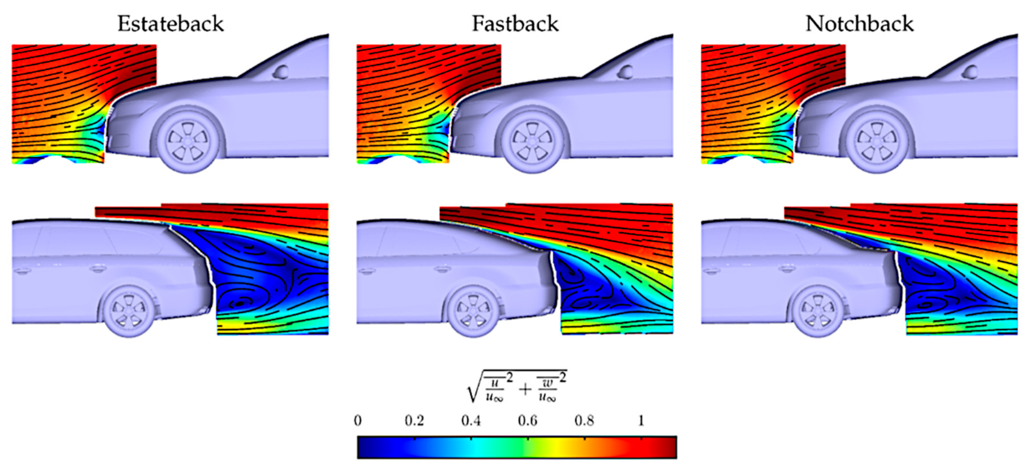
Figure 1: PIV planes of normalized velocity magnitude at midspan section for DrivAer configurations. Adapted from Ref. [21] under the Creative Commons Attribution-NonCommercial (CC BY-NC 4.0) license.
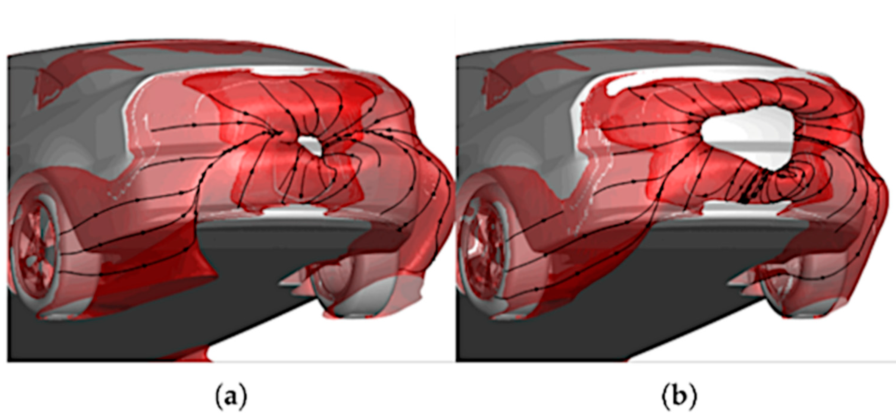
Figure 2: Iso-surface of the time-averaged total pressure coefficient (equal to −0.025) overlayed with streamlines for (a) stationary and (b) rotating wheels. Reproduced from Ref. [23] under the Creative Commons Attribution (CC BY) license.
This section offers a look at aerodynamic research conducted on production cars, with different goals. Hints are provided on both the numerical and experimental sides. Although this review focuses more on numerical and wind tunnel techniques, it should not be forgotten that the tools available to engineers also include road and track testing. While wind tunnel testing and CFD simulations are used in almost all stages of vehicle development, road and track testing become valuable to quantify the aerodynamic drag of final products and fully engineered vehicles. This class of techniques for the measurement of aero performance is deceptively easy to implement: track time and vehicle support are usually expensive, suspension vibration and change in ambient conditions may impact the outcome [8].
To quantify road loads it can be relied upon “coast-down method” and “constant-speed method”. The difference between the two methods depends on the type of motion of the vehicle. In a coast-down scenario, there is no tractive force and the vehicle decelerates because of aerodynamic, rolling resistance, and mechanical resistance forces [31]. In a constant-speed scenario, the tractive force is balanced by aerodynamic and rolling resistance; the mechanical resistance force is no longer applicable because it operates upstream of the wheel-ground interface at which the tractive force is applied. Tests are performed at numerous (constant) speeds to build a road-load characteristic from which the aerodynamic drag and rolling resistance components can be inferred. A procedure example is outlined in [32] for a heavy-duty vehicle. Moreover, the reader is referred to [33] for a more detailed comparison between the two methods: a good agreement in the drag area data was stated, with less than 1% difference.
Indeed, coast-down testing is very common in the automotive industry and allows the mechanical and aerodynamic resistance acting on a vehicle to be measured. This test is based on Newton’s 2nd law: the vehicle is accelerated to a target speed on a flat track, then it is allowed to slow down in neutral with the engine idling. Measurements of coasting time, speed and position are processed to trace back to mechanical resistance and aerodynamic drag. Coast-down tests are standardized and constantly revised to improve accuracy: the Society of Automotive Engineers updated in 2020 the procedure for determination of vehicle road load force for speeds between 115 km/h and 15 km/h: the final result is a model of road load force (as a function of speed) during operation on a dry, level road under reference conditions of 20°C, 98.21 kPa, no wind, no precipitation, and the transmission in neutral [34]. In parallel to the coast-down procedure, this aforementioned SAE standard illustrates the real-time onboard anemometry to measure and compensate for potential wind in front of the vehicle. The coast-down results are also used to calibrate a chassis dynamometer, in order to replicate performance tests in a repeatable and controlled environment without the influence of variable external conditions [35].
Turning to wind tunnel testing, Kee et al. [36] studied the behavior of a Hyundai passenger car at high speed and in crosswind conditions by full-scale wind tunnel experiments, on-road tests and track tests with a crosswind generator. Measurement results showed that driving stability depends not only on the aerodynamic features of the car, but also on the dynamics characteristics, suspensions, and weight distribution. From an aerodynamic point of view, they came to the conclusion that the reaction rate of high-speed stability improves by minimizing total lift, side force and yawing moment. However, they did not mention road adhesion, a crucial factor in maintaining control and stability. Aerodynamic lift can counteract the vehicle’s weight, thus reducing tire-road adhesion and causing a large lateral motion of the vehicle, which in turn leads to changes in the flow field surrounding the vehicle body. Therefore, a two-way coupling model is needed, based on aerodynamic and dynamic models [37]. In crosswind conditions, an unstable location of the separation line at the rear of the vehicle is a source of instability: the use of sharp corners can help to maintain a fixed separation line [2].
As explained before, if the objective is to measure the aerodynamic drag, a coastdown experiment can be performed. Different configurations of a full-scale sedan car (Fiat Linea) were tested to estimate the contribution of engine-cooling airflow and detailed underbody configurations to overall drag [38]. CD was found to increase by about 10% and 15%, respectively. This was also confirmed by steady RANS simulations with Realizable k-e (Rke) two-layer turbulence model.
When it comes to production vehicles, the focus is often on wake generation and development. Kounenis et al. [39] examined the complex three-dimensional flow structures at the rear end of a 30% scale model of Volvo S60 2003MY and a full-scale Volvo S60 2010MY, starting with the analysis of the rear end topology (rear window and the trunk deck). Several techniques were employed, including surface flow visualizations, force measurements, PIV as well as steady RANS simulations with Rke turbulence model. CFD modelling, compared with PIV measurements in the wind tunnel, overestimated the wake length while correctly predicting the main vortex structures. Details can make a difference when dealing with the near wake, as demonstrated experimentally by Rossitto et al. [40]: PIV applied to the symmetry plane revealed that rounding the pillar (Fig. 3b) can shorten the length of the mean separated region compared to the case with sharp rear end (Fig. 3a), while deeply affecting the organization of the two counter-rotating inner structures, which move closer to the vertical base. Similarly, in [41], two variants of spoiler on the roof of a SUV were considered to highlight differences in wake dynamics in crosswind conditions, but with the aim of assessing their impact on driving stability. Simulations with SBES turbulence model showed that the up-washed spoiler (Fig. 4b) creates a more stable wake than the base spoiler (Fig. 4a), also reducing low-frequency lift fluctuations. Note that the red lines in Fig. 4 mark the wake balance.
In addition to established research on vehicle bodywork, interest in wheels and ride height has been growing in recent times. Bastian et al. [42] proved that the ride height of a passenger car (i.e., BMW 3 Series sedan) increases by several mm (up to 7) when driving at 140 kph, compared to still conditions, due to centrifugal forces radially expanding the tyres and aerodynamic lift forces. Moreover, size and design of the wheels may contribute to this phenomenon, affecting the aerodynamic lift and drag more than has been quantified by wind tunnel testing at fixed ride height. Measurements made by laser sensors were supplemented by LBM-based simulations with renormalization group k-epsilon turbulence model. Tyre deformation caused by wheel rotation was also addressed by Čavoj et al. [43]. The authors showed that, as tyres expand radially and vehicle ride height increases, aerodynamic drag rises because of higher mass flow through the underbody, given the increased ground clearance. On-road measurements on a Skoda Octavia RS confirmed that the ride height increases by about 4–6 mm on both axles only due to radial expansion of the tires.
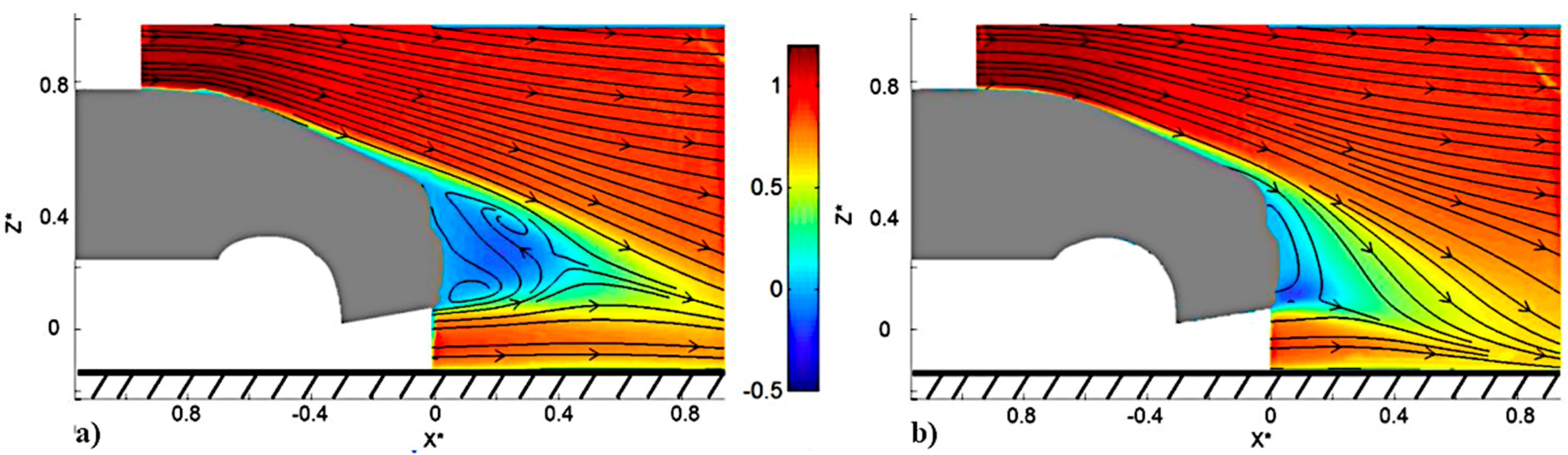
Figure 3: Measured (normalized) velocity contours and streamlines at midspan section for a realistic model: (a) sharp rear end; (b) rounded rear end. Reproduced from Ref. [40] under the Creative Commons Attribution (CC BY) license.
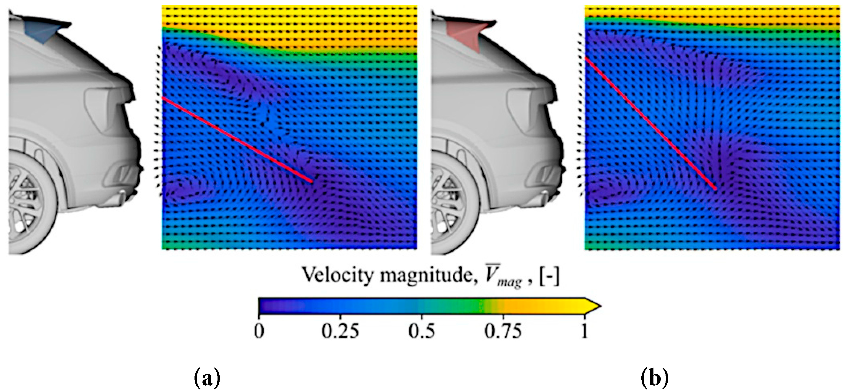
Figure 4: Simulated (normalized) velocity contours and vectors at midspan section for a realistic model: (a) baseline spoiler; (b) improved spoiler. Reproduced from Ref. [41] under the Creative Commons Attribution-NonCommercial-NoDerivatives (CC BY-NC-ND 4.0) license.
3 Aerodynamic Drag Reduction by Passive Flow Control
Passive flow control means influencing the flow without the need for external energy. Physical modifications can be used (like vortex generators or surface roughness) to manipulate airflow without external power, making it relatively cheap and simple. Although less expensive than active flow control, it cannot be “turned off”: working constantly may cause potential drag when flow control is not needed.
3.1 Passive Flow Control over Simplified Geometries and Blunt Bodies
3.1.1 Vortex Generators, Streaks and Riblets
The theoretical background behind the use of these devices is well established in the literature and, of course, goes beyond automotive application. In general, a vortex generator (VG) injects energy into the boundary layer from the outer flow, preventing it from separating further: although it is used primarily to control already separated flow, in some cases, it is effective in delaying the onset of separation [44]. Riblets can have a twofold effect, reducing both friction and form drag [45]: they lower drag by lifting vortices formed in the turbulent flow thus decreasing overall shear stresses and they also reduce the boundary layer displacement thickness, leading to changes in the pressure distribution, particularly in the adverse pressure gradient region”.
Aider et al. [46] characterized the aerodynamic behavior of a modified Ahmed body equipped with non-conventional trapezoidal VGs using the PIV technique. VGs appear to be very efficient in reducing drag and lift by up to 12% and 60%, respectively, although the results are significantly affected by their geometric features (such as longitudinal position) and freestream velocity. The reason for this is to be found in the physics of the wake: the greater reduction in drag and lift is associated with a large increase in the size of the recirculation bubble above the rear slant and a simultaneous reduction in the strength of the longitudinal trailing vortices. It can be inferred that the total drag of low-aspect ratio blunt bodies, such as road vehicles, can be reduced by triggering early separation, when the trailing vortices and the recirculation bubble interact in the near-wake. In fact, the boundary layer separation over the rear slant occurs just upstream the VGs: this means that, unexpectedly, they do no not delay but rather trigger the separation of boundary layer, which is dominated by the regions of outward flow. Pujals et al. [47] demonstrated how to suppress the separation at the rear end of an Ahmed body by large-scale streaks. These, generated by an array of cylindrical roughness elements on the roof of the model, completely extinguish the recirculation bubble at the rear end, thus leading to a 10% reduction in drag. In contrast to [46], this is achieved by delaying the flow separation caused by the adverse pressure gradient. This separation delay is caused by the spanwise modulation of the mean flow associated with large-amplitude coherent streaks.
Yang et al. [48] simulated two combined drag reduction techniques by applying the IDDES approach. Hemispherical VGs and riblets added on the rear and slant surface of the Ahmed body, working together, can reduce the overall aerodynamic drag. In fact, the separation bubble is weakened for most of the combinations depicted in Fig. 5. At best, VGs on the slant surface generate small counter-rotating vortices behind the near-wake region, which affect the formation of the separation bubble, while the riblets on the rear surface restrict the near wall spanwise flow, thus causing a total drag reduction of 8.6%.
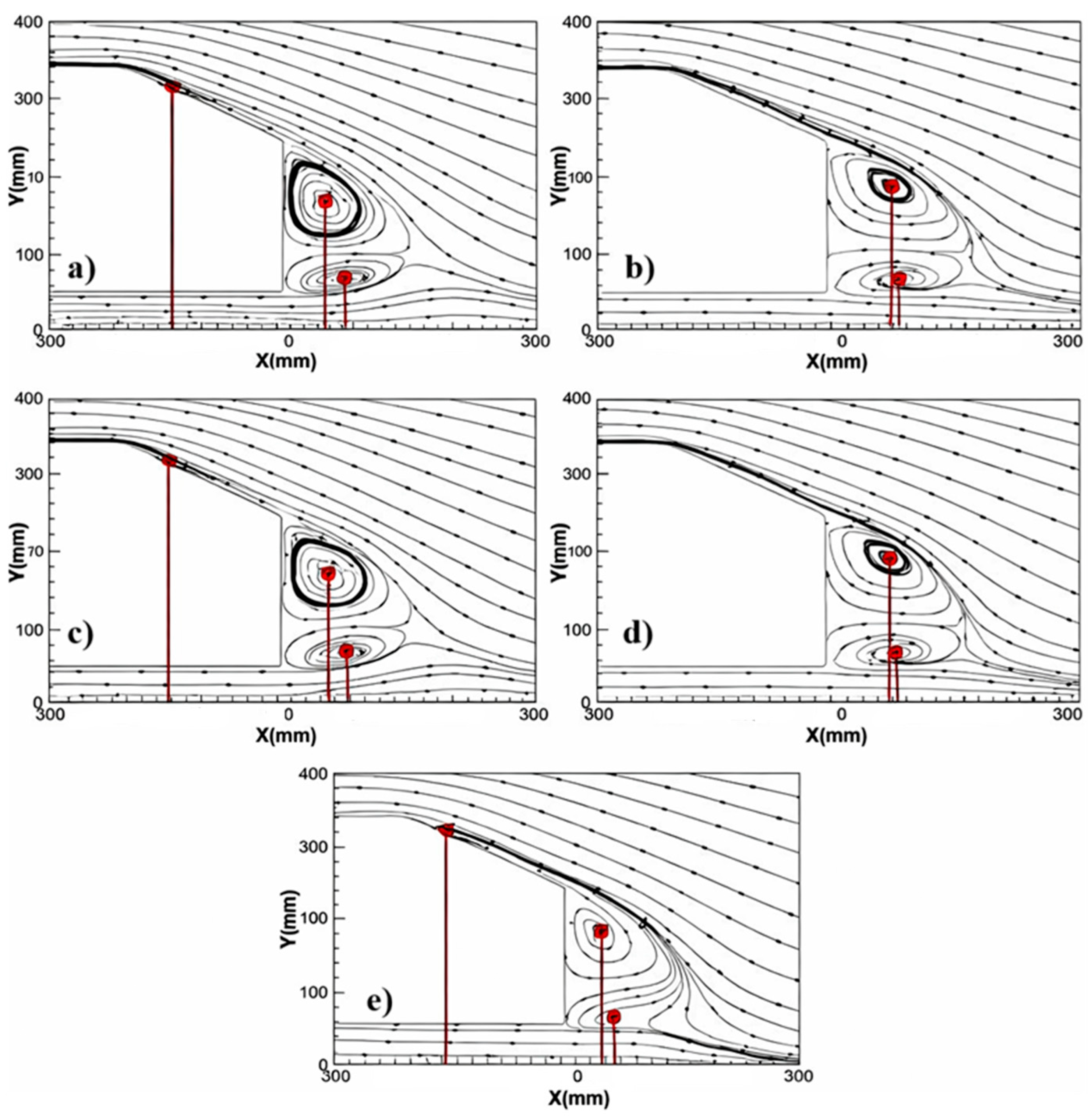
Figure 5: Comparison of time-averaged flow fields at midspan section: (a) Baseline Ahmed body; (b) VGs added on both the slant and rear surfaces; (c) VGs added on the slant surface with riblets added on the rear surface; (d) Riblets added on the slant surface with VGs added on the rear surface; (e) Riblets added on both the slant and rear surfaces. Reproduced from Ref. [48] under the Creative Commons Attribution-NonCommercial (CC BY-NC 4.0) license.
3.1.2 Cavities, Boat Tailing, Rounded Edges, and Chamfers
The literature provides many examples of rear-mounted devices that can impact the wake structure so as to reduce the overall drag of blunt bodies. Grandemange et al. [49] optimized the squareback Ahmed body by introducing chamfers at the top and bottom edges of the rear face: the achieved drag reduction is 5.8% compared with the reference geometry. Due to the curvature introduced by the flow orientation at the edges, the pressure level at the top and bottom is lower than that at the left and right. The pressure differences cause three-dimensional separation and vortex formation around each corner at the base. Thacker et al. [50] achieved a 10% drag reduction by means of a rounded edge which prevents flow separation at the rear of a 25° slanted Ahmed body, compared to a configuration with a sharp edge at the junction of the roof and the rear slant. The suppression of the separation bubble is due to the increase in the local radius of curvature of the edge between the roof and the rear window, resulting in a higher static pressure coefficient over most of the central region of the rear window.
Khalighi et al. [51] modified the back of a squareback Ahmed body with two devices: a box with a cavity and a boat-tail without a cavity to improve pressure recovery and reduce the flow unsteadiness. Unsteady Reynolds-Averaged Navier-Stokes (URANS) simulations, supported by corresponding experiments in a small wind tunnel, reveal drag reductions of 18% and 30%, respectively. The recirculation regions at the base shorten and weaken, and the base pressure increases significantly. The use of rear cavities on a squareback Ahmed model was also experimentally evaluated by Lorite-Díez et al. [52]. They tested a straight cavity and a curved cavity inside an Eiffel-type wind tunnel. The latter offers greater attenuation of the fluctuating wake and more significant base pressure recovery than the former. Indeed, the straight cavity loses its effectiveness under moderate crosswind conditions, despite being known as a robust drag reduction device for car models.
An evolution of the straight cavity was proposed by Urquhart et al. [53]. A Windsor model is equipped with a tapered cavity which further reduces crossflow and results in a smaller wake with less losses. The base pressure is increased and the wake gets more balanced. Near-wake crossflow was found to be one of the most important qualitative indicators of overall drag.
Further studies about base cavities and rear tapering show that drag reduction is achievable, but the improvements may lack consistency due to the influence of many geometric variables and flow conditions. Bonnavion and Cadot [54] experimentally tested various angles of after-body boat-tailing on a three-dimensional blunt model working close to the ground. The wake dynamics turned out to be strongly dependent on the coupling of top and bottom boat-tail angles and dominated by large crossflow force fluctuations. Howell et al. [55] investigated different techniques to reduce the drag of a squareback Ahmed body exploiting the principle of base pressure recovery. The previously mentioned model was equipped with a base cavity of variable depth, which can be ventilated by slots. The plain cavity offers a significant drag reduction for a wide range of cavity depth. In case of addition of ventilation slots, in can be seen that their effectiveness depends on cavity depth, slot geometry and distribution on the perimeter of the base area. Besides the use of cavity in various forms, the tapering of the upper rear body (roof and sides) of a Windsor model was also investigated [56]. The study varied the rear taper angle (from 5° to 25°) and taper length, comparing the results to a baseline squareback configuration. Significant drag reduction can be obtained with moderate taper angles. However, a drag peak is encountered at a particular taper length.
3.1.3 Spoilers, Splitters, Deflectors, Flaps and Ducts
The rear spoiler is arguably the most common automotive aero device, playing a crucial role in determining the vehicle’s wake features and aerodynamic efficiency. In line with recent trends, numerous SUVs are now equipped with perforated rear spoilers. In their study, Zhou et al. [57] conducted a numerical investigation into the effects of a spoiler with six different opening areas (ranging from 0 to 11,904.50 mm2) on a 35° back slanted Ahmed body (see Fig. 6). The results, presented in Fig. 7, demonstrate that, in comparison to the baseline scenario without a spoiler (CD = 0.279), four out of six tested configurations resulted in CD reduction. However, no consistent trend was identified between the opening area and the percentage drag reduction. The best spoiler configuration (case 2 with an opening area of 2917.50 mm2) led to a 6.5% drag reduction, mainly due to improved rear-end pressure recovery (Fig. 8). In fact, the spoiler allows for greater kinetic energy over the slant, enhancing the boundary layer’s capability to cope with the adverse pressure gradient. Accordingly, static pressure on both the slant surface and base increases.
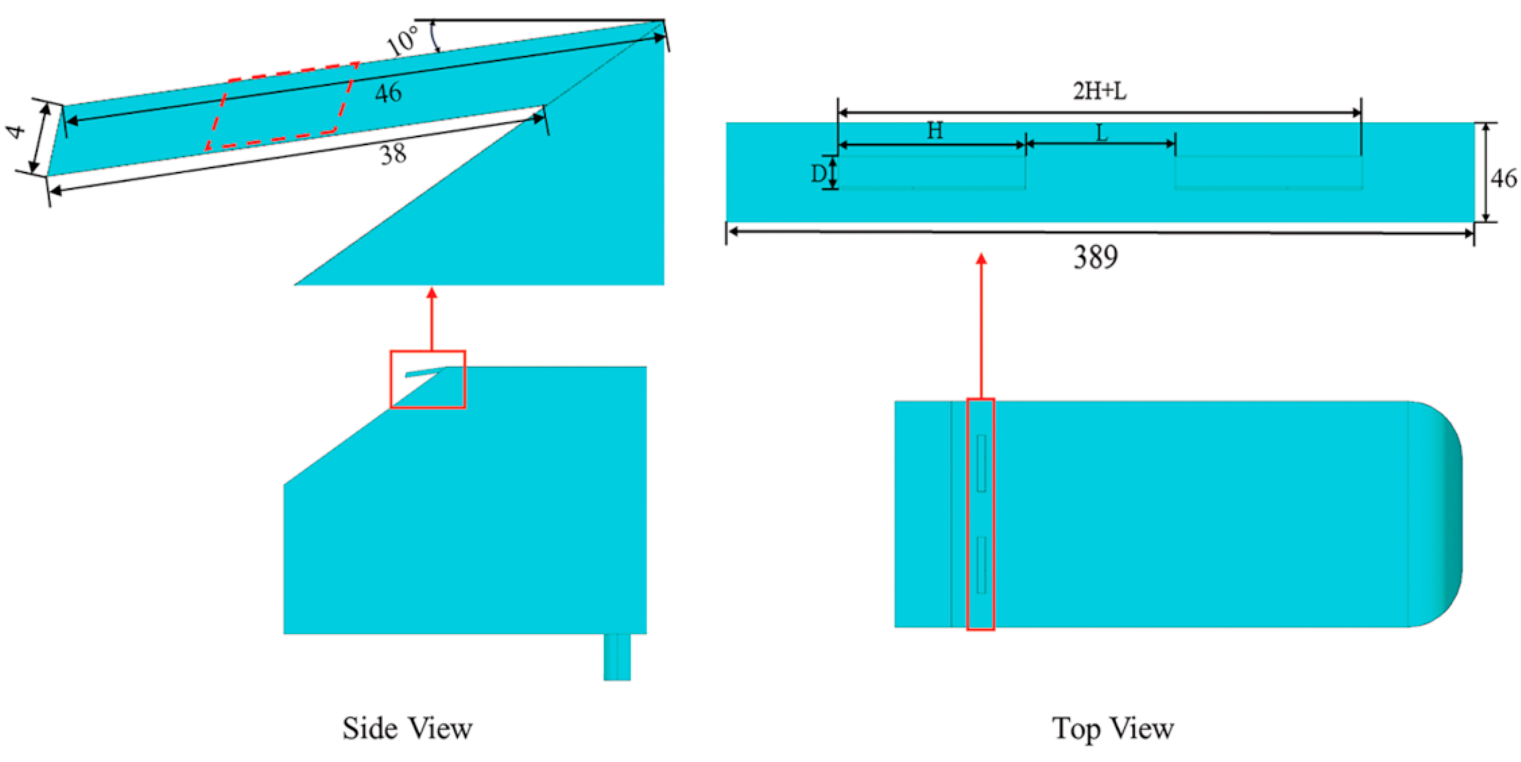
Figure 6: 35° slanted Ahmed body—detailed view with a hollow roof spoiler. Reproduced from Ref. [57] under the Creative Commons Attribution (CC BY 4.0) license.
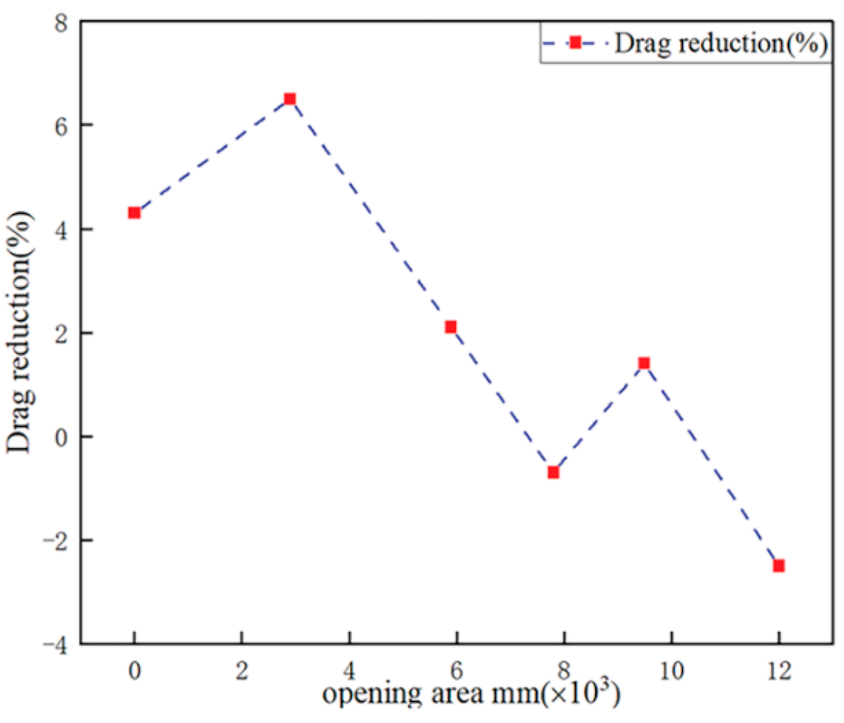
Figure 7: Drag reduction for each opening area, calculated relative to the baseline case. Reproduced from Ref. [57] under the Creative Commons Attribution (CC BY 4.0) license.
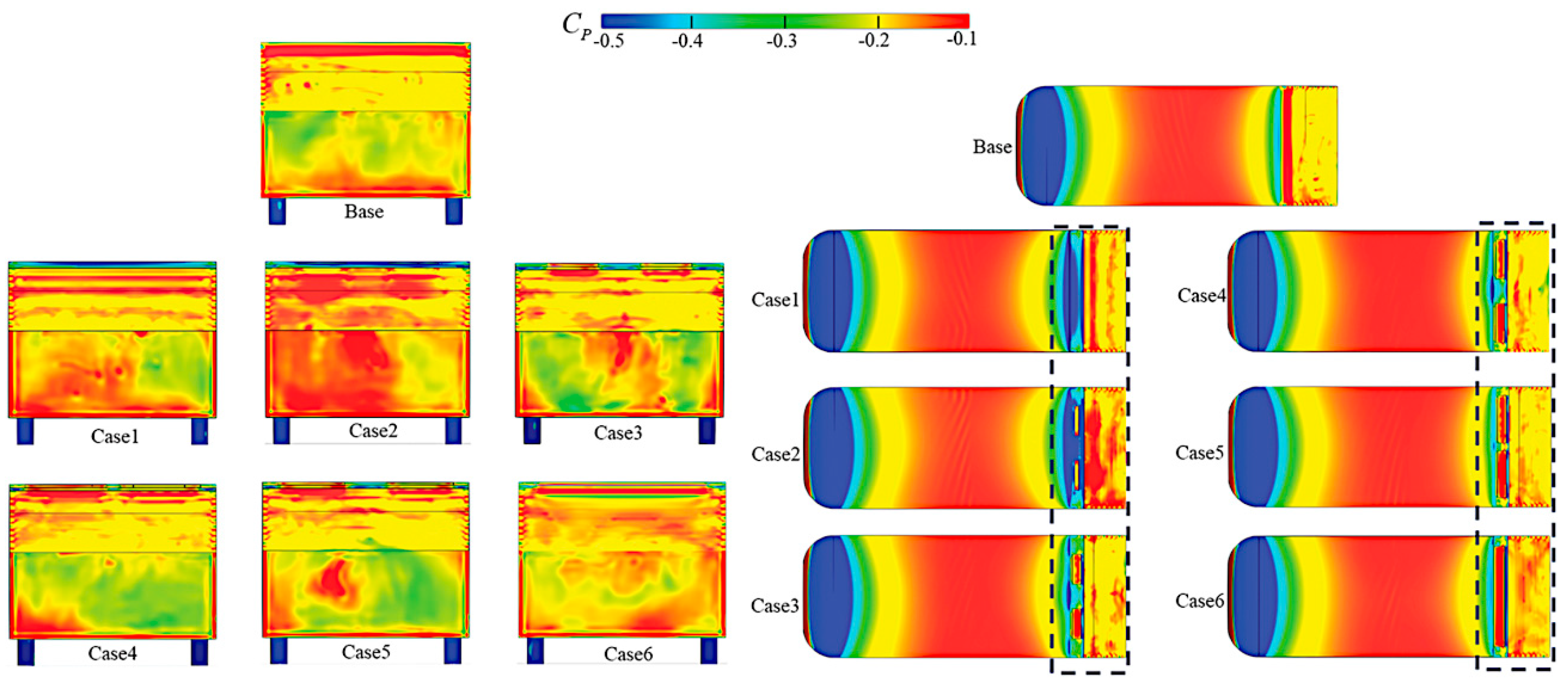
Figure 8: Average surface pressure coefficient of Ahmed body—base and upper views. Reproduced from Ref. [57] under the Creative Commons Attribution (CC BY 4.0) license.
Other devices have been borrowed from the aviation industry to pursue the goal of drag reduction. The tapered cavity presented in [53] was improved with nine angled surfaces, or flaps, distributed at the trailing edge of the cavity along the roof and sides of the Windsor model [58]. Analysis of the flow field using tomographic PIV and base pressures suggests that wake balance is the key: drag reduction in steady crosswind conditions comes from reducing both the strength of a large leeward side vortex and the crossflow within the wake. Unexpectedly, wake unsteadiness and base pressure fluctuations alone could not be linked to changes in drag. The use of flaps for drag and lift reduction purposes was deeply examined by Beaudoin and Aider [59]. Each edge of the two rear panels of a standard Ahmed body was fitted with flaps and tested at different freestream velocities in the PSA in-house wind tunnel. Measurements were made by varying the angle of inclination between the body walls and the flaps. At best, with cumulative effects between combinations of different flap configurations, drag can be reduced by 25% and lift by 107%. With the lateral flaps around the rear slant, PIV measurements showed that the most significant drag reduction corresponds to fully separated flow over the rear slant: the streamwise vortices are suppressed and the separation bubble is free to grow. This is very specific to 3D bluff bodies and contrary to the aeronautical principle of lowering drag by delaying the separation and thus reducing the recirculation bubble.
Instead, Fourrié et al. [60] and Hanfeng et al. [61] focused on experiments related to deflectors mounted on a typical slanted Ahmed body. In the former a deflector was placed on the upper edge of the model rear window. Depending on the deflector angle, a reduction in drag of up to 9% was achieved: the deflector increases the separated region on the rear window, but, at the same time, interrupts the counter-rotating longitudinal vortices on the lateral edges of the rear window. In the latter, deflectors were placed at the side edges and leading edge of the slant. The measurements suggested that, over a certain threshold, the side edge deflectors become increasingly effective in reducing drag as their height grows. Moreover, the leading-edge deflector is more efficient than that at the side edge in suppressing both the separation bubble and the longitudinal trailing vortices (i.e., C-pillar vortices).
The original approach of Gilliéron and Kourta [62] involves the use of vertical splitter plates positioned at the rear or front of a simplified car geometry, with the aim of reducing the surface of the wake that contributes to the drag force. By choosing different positions and orientations in relation to the flow conditions, a significant drag reduction can be achieved. Specifically, vertical splitter plates positioned downstream of the base reduce drag by up to 12%, depending on the size of the splitter plates and the distance between the splitter plate and the base; splitters positioned upstream of the body can provide drag reductions of nearly 27 and 45% depending on the angle of inclination from the vertical.
The unconventional passive aerodynamics proposal of Mohammadikalakoo et al. [63] makes use of linking tunnels at the rear of the Ahmed body, blowing the high-pressure flow from the sidewalls to the low-pressure wake region. Both wind tunnel testing and steady RANS simulations with SST k-ω turbulence model confirmed that the wake size is reduced, and with it the drag (up to a maximum of 5%). In detail, the central wake’s vortices are smaller and the C-pillar vortices are thinner due to the addition of the linking tunnels to the Ahmed body. Interestingly, the reduction in drag increases with the freestream Reynolds number and with the slant angle (φ) of the model.
3.2 Passive Flow Control over Realistic Models and Production Vehicles
In the milestone study by Carr [64], the drag of a popular hatchback, the Austin Maxi, was potentially reduced by up to 31% through the use of several add-on devices. The detailed schedule of modifications was determined by considering not only the shape of the vehicle but also the feasibility of the adjustments, thus the undertray of the car was not considered. Major changes to basic geometry included: air dam, A-pillar post vanes, flush wheel discs, rear wheel spats, rear spoiler on the roof and on the boot. Road and wind tunnel tests led to the following conclusions: there is some evidence of interference effects between different devices mounted simultaneously on the car (superposition principle is not valid); the most effective single add-on devices are the front spoiler (air dam) and the roof-mounted rear spoiler; the less significant modifications in terms of drag reduction include flush wheel discs, rear wheel spats, and vanes fitted to the A-posts. In the wake of this work, this section highlights current key issues in aerodynamic optimization.
3.2.1 External Aerodynamics: Shape and Detail Optimization
Shape and detail aerodynamic optimizations currently affect different types of vehicles, from compact cars to large SUVs. Ferraris et al. [65] described in detail the drag reduction process of a city-car prototype, the XAM 2.0, by means of standard aerodynamic devices (spoiler, finlets, rear underbody, front bumper, rear dam, and wheel cover). Steady RANS simulations, coupled with the Rke two-layer turbulence model, were performed to design different add-on features, which were manufactured and then tested in the Pininfarina Wind Tunnel. At best, the studied features led to a global CD reduction of more than 7%, corresponding to a fuel consumption reduction of about 2 km/l. The increasing focus on fuel efficiency in compact cars is evidenced by Repmann and Hähnel [66]: they reported the aerodynamic development of the 7th Generation Volkswagen Polo, which relies on hundreds of hours of wind tunnel testing both for the platform and the car body. Despite being a very cost-sensitive small vehicle, it is equipped with a comprehensive set of underbody panels. A new type of brake cooling duct was designed to lower air mass flow and guide it more precisely to the caliper. In addition, wheel deflectors and acoustic stiffeners were optimized. The upper body was affected by the following changes: increased φ of the roof, increased tapering of the lateral rear end, reduced vehicle base area, and optimized shape of the A-pillar. Unfortunately, some of the improvements in CD (−8% over the previous model) were negated by the increase in the frontal area of the vehicle (+4%).
As regards SUV aerodynamics, a good example of combined numerical and experimental development process was provided by Chaligné et al. [67]: the fourth-generation Land Rover Discovery was designed with special attention to CD. The commercial CFD code EXA Power-FLOW, which provides a Very Large Eddy Simulation turbulence model based on a Lattice Boltzmann solver, was used to optimize the main proportions of the vehicle. In the delivery phase, CFD was still used but in combination with experiments in the MIRA Full Scale Wind Tunnel. Many car body parts were involved in the process, as explained below. The front corners were improved by a combination of conventional shape optimization and the development of an air curtain, to further control the flow around the front wheels and the wheel arches. The underfloor was heavily redesigned: engine, transmission, and side under-trays were added to tank shields, tank deflectors, a spare-wheel heat shield, and profiled suspension arms. As for the upper car body, a slotted roof spoiler was developed to reduce the rear glass soiling. In addition to eco-wheel rims, the Discovery was equipped with active air suspensions for lowering the ride height when cruising at motorway speeds. The contribution of all the aforementioned devices resulted in a CD of 0.33.
Interesting research may also arise from synergies between universities and automotive industries. Korea Aerospace University and Hyundai Motor Company joined forces to numerically investigate the effect of boat tailing on the aerodynamic drag of a commercially available SUV [68]. Steady RANS simulations with Rke turbulence model showed that applying a boat tail shape to the SUV without an undercover does not contribute to reducing CD. On the contrary, with an undercover, there is a beneficial effect on CD because the airflow from the roof, aided by the underbody flow, can weaken the strength of longitudinal vortices in the wake. The complexity of the phenomena that determine the aerodynamic behavior of SUVs emerges from the work carried out by Chalmers University of Technology in collaboration with Volvo Car Corporation [69]. The side wind effects on drag were examined, from 0° to 5° yaw, for three geometrical configurations of the Volvo XC60 AWD:
- (a)without extensions, referenced to as the baseline (A),
- (b)with smooth tapered extensions (B),
- (c)with tapered extensions with kick (C).
A hybrid RANS-LES method, such as IDDES with SST k-ω turbulence model, was chosen to run CFD simulations. The numerical outputs were then analyzed by spectral methods and proper orthogonal decomposition to investigate fluid flow patterns and extract turbulent structures. The smooth extensions provided the greatest drag improvement at 0° yaw while the extensions with a kick yielded benefits at 5° yaw, effectively reducing the vehicles drag sensitivity to side wind.
In the wake of the previous research, Urquhart and Sebben [70] focused on a full-scale Volvo XC40 with an added base cavity and movable flaps under yaw conditions (0°, 5° and 10°). The cavity extended the rear geometry of the SUV by approximately 150–200 mm (5% of the vehicle length). Moreover, the trailing edge of the cavity was fitted with 12 moveable 80 mm long flaps (2% of the vehicle length). The servo-controlled flaps angles were continuously optimized by means of a surrogate model-based optimization algorithm with the objective of reducing the aerodynamic drag at different yaw conditions and generating a yaw-insensitive geometry. Indeed, the cycle averaged drag optimized design proved to have a smaller increase in drag when yawed compared to the case without yaw.
Connolly et al. [9] focused on inflatable and alternative material devices for obtaining single-cavity and multi-cavity designs (Fig. 9), with the aim of reducing rear drag of production vehicles. Road tests and CFD simulations were conducted on a VW Golf Mk7 and a Citroen Berlingo L1 H1 van. The tested components included: five inflatable rear cavity devices, one foam device, a rigid triple-cavity device, and a drag-reducing roof ramp. The most notable road-tested result for an inflatable device was a 13.5% reduction in overall drag on the Citroen Berlingo equipped with a triple cavity. The foam cavity mounted on the VW Golf Mk7 produced a drag reduction of approximately 20%, resulting from a 50% increase in base pressure inside the cavity.
Hu et al. [71] numerically investigated different diffuser angles on a simplified sedan car, while Palanivendhan et al. [72] focused on VGs: when placed on the rear windshield, at a specific distance upstream of the flow separation point, they play a key role in reducing drag, from 12 to 15%.
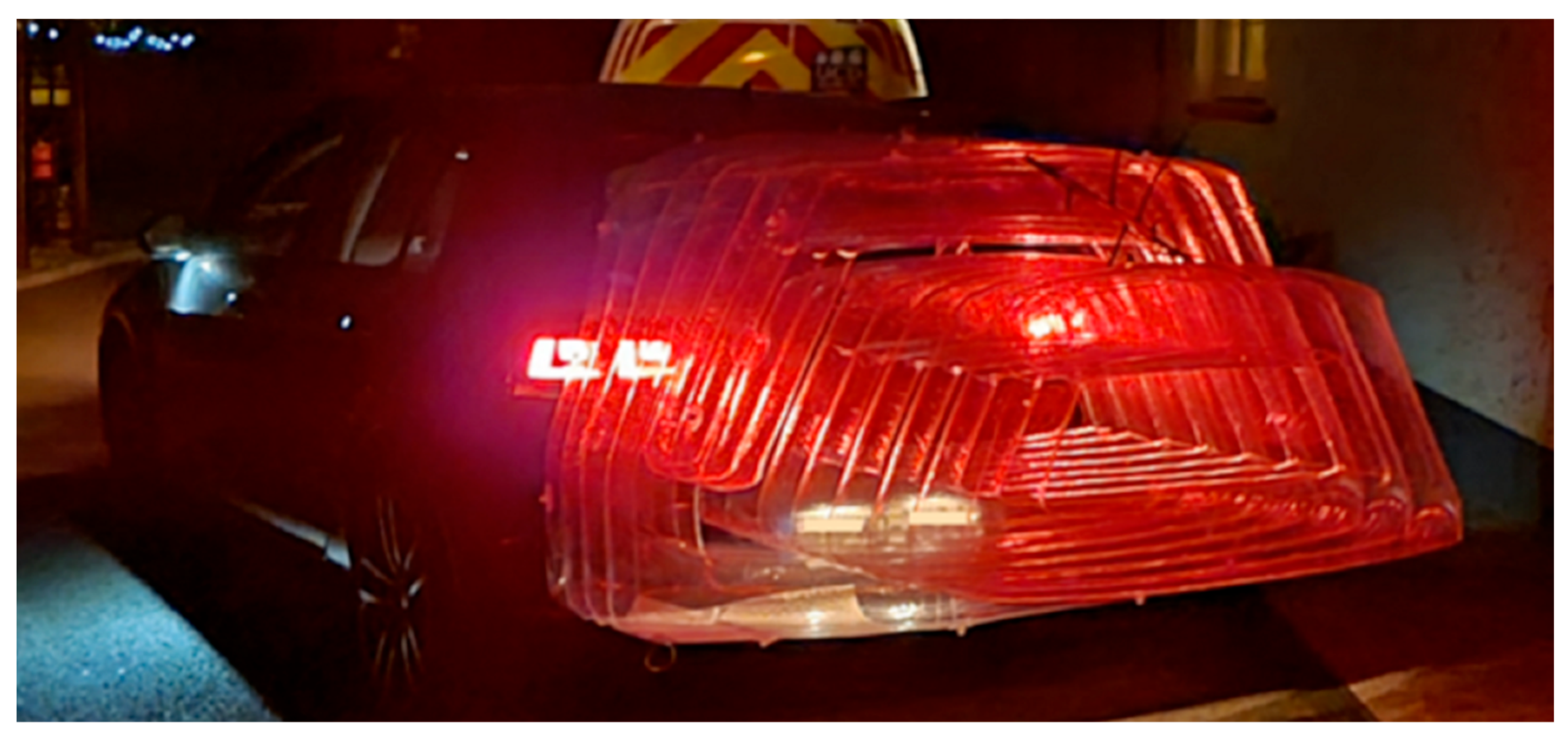
Figure 9: Inflatable double-cavity device. Reproduced from Ref. [9] under the Creative Commons Attribution (CC BY) license.
When it comes to optimising the aerodynamics of road-legal sports cars, reducing CD is not the only goal, because engine performance should go hand in hand with enhanced vehicle dynamic behaviour. Lateral forces between the tyres and the ground increase with the vertical load, therefore aerodynamic lift should be as low as possible or, better yet, negative. Dickison et al. [73] provided a good example of aerodynamic development of a sports car by optimizing both drag and lift coefficients for the front, middle and rear of the vehicle. They adopted a combined experimental and numerical analysis: wind tunnel tests were set together with steady RANS simulations, with standard k-e turbulence model, to understand the aerodynamic structure of the concept vehicle and suggest modifications to improve its performance. Several geometric changes were introduced including front air curtain, new location for the number plate, side ducts behind the front wheel arches, new roof curvature, intercooler vents, rear air outlets and rear wheel arch ducts. Indeed, some of the solutions identified, although designed for a high-performance car, could be applied to cars for daily use.
Another branch of research concerns the optimization of internal flows (e.g., engine cooling flow), which have a significant impact on total vehicle drag and heat transfer efficiency. As the following studies testify, current road cars have great room for improvement in this regard. Whatever method is applied, experimental or numerical, research on internal flows encompasses very complicated geometries that include the following components: front grille, intercooler (if necessary), condenser-radiator-fan module (CRFM, in short), engine block, front subframe, front wheelhouse and engine room undercover. Cooling airflow is essential for the vehicle air conditioning system and the engine cooling module. Specifically, the cooling airflow in the engine room exits through the front subframe and mixes with the external flow upstream in the underbody: the mixing process between external and internal flows affects the aerodynamic drag of the vehicle.
In Yang et al. [74], an air guide attached to the centre floor undercover of a sedan-type vehicle was designed and simulated, with the aim of directing cooling airflow to the rear section of the underbody. Numerical results from RANS simulations, with Rke turbulence model, showed that the greater the cooling airflow to the rear section of the underbody, the larger the reduction in drag. Indeed, the air guide not only prevents spreading out of cooling airflow exiting from the front subframe but also pushes the cooling airflow from the front wheelhouse to the rear underbody. Overall, CD can be reduced by about 2% with this simple add-on device. Similarly, in the work by Cho et al. [75], a combination of drag-reducing devices was applied to the underbody of a sedan-type vehicle, including undercover, under-fin and side air dam. In the RANS simulations, with Rke turbulence model, the complexity of the underbody flow was accurately modelled taking into account several components such as front grille, radiator, fan, engine hood, engine compartment (with generator, crankshaft, battery, cooling tank) and wheels. The numerical analysis showed that the undercover reduces the rear wake region through the attenuation of the longitudinal vortex pair: the benefit in terms of drag reduction is about 8%. The under-fin and side air dam are effective only when combined with the undercover.
However, research on internal flows is not only about the cooling flow path and mixing with the main external flow. Kim et al. [76] focused on the grille opening shape of a small passenger car, using a parametric numerical study based on the RANS approach, with Rke turbulence model. Several geometric parameters (vertical height, horizontal width, size, linear deformation, position, and blockage) were considered for the design, with a twofold objective: the grille must ensure both low drag and adequate inlet flow, so as not to compromise the powertrain cooling performance. They recommended ranges of variation for each of the listed geometric parameters from the baseline model. Another remarkable example of internal flow optimization was provided by Zhang et al. [77]. The influence of the front-end configuration (which typically consists of a CRFM) on radiator performance and cooling drag was assessed through a series of CFD simulations on a full-scale vehicle (Hyundai Veloster). The method chosen is again steady RANS, with Rke turbulence model. As mentioned above, CRFM should provide an optimum performance of the cooling system while contributing to the reduction of vehicle drag. Accordingly, six cases with two different types of air-ducts between the grille and the radiator, two front grille-opening configurations, and two different orientations of the CFRM were tested numerically. In addition, the performance of the radiator was predicted under different operating conditions: at idle and highway speeds, with stationary or rotating fan. The results revealed that a vertical CRFM has poor cooling performance and high cooling drag. Furthermore, the introduction of an air duct, in combination with modified CRFM orientation and grille openings, can greatly improve the quality of the underhood airflow, at both highway speed and idle conditions. In the former case, the radiator benefits from increased flow rate and airflow uniformity thus enhancing cooling performance; in the latter case, the so-called “hot-air recirculation” is attenuated thus improving the performance of the heat exchangers.
In summary, the installation of a cooling system usually adds the so-called “cooling drag” to the vehicle. For most passenger cars, cooling drag falls within the range of ΔCD ≈ 0.01–0.07, but most of them are closer to 0.03–0.05 [8]. However, if the cooling system is designed according to the optimization techniques described above, cooling drag close to zero is also possible.
In realistic conditions, approximately 25%–30% of a passenger vehicle’s aerodynamic drag comes directly or indirectly from its wheels and wheelhouses (Brandt et al. [78]; Elofsson and Bannister [79]; Regert and Lajos [80]). Especially on low-drag vehicles, the percentage contribution of wheels to the overall car drag becomes considerable. As a result, their aerodynamic improvement is gaining more and more attention, both from the perspective of the wheel rim and the tyre. Landstrom et al. [81] experimentally studied the aerodynamic influences of tyre size (215/50R17 and 215/55R16) and geometry in combination with three different wheel designs. Results put in evidence that different configurations can lead to variances between 5–10 drag counts, depending on tyre and rim combination.
Hobeika et al. [82] studied the effect of tyre profile, tyre tread, rim design and spoke orientation on the aerodynamics of two types of road vehicles: a sedan and a sports wagon. Moreover, different sets of tyre deformation due to vertical loads and centrifugal forces, were replicated in the CFD simulations based on the steady RANS method, with Rkε turbulence model. More than sixty configurations were numerically tested and, whenever possible, results were compared with experiments conducted in the Volvo Car Aerodynamic Wind Tunnel, which is equipped with a 5-belt ground-moving system, a boundary layer meter, suction and tangential blowing. This extensive campaign of simulations and tests revealed a few important points: first, tyre profiles and patterns have different effects on drag and lift so realistic geometries should be used in simulations; second, the addition of main grooves causes a constant reduction in drag and lift and finally, the magnitude of changes in aerodynamic forces due to tyre characteristics depends on the rim. Likewise, Kulak et al. [83] compared slick tyres with grooved tyres by means of CFD modelling (steady RANS method with SST k-ω turbulence model) in combination with wind tunnel tests and PIV measurements. One of the most relevant findings is that the number and position of longitudinal grooves strongly affect the tyre drag, consistently with [82]. Moreover, the location, amount and shape of the longitudinal grooves can improve airflow around the wheels and the whole vehicle as well. This research also suggested that, to some extent, optimized tread patterns can be inferred by isolating the individual tyre, regardless of the car body on which it is mounted, thus saving development costs. Josefsson et al. [84] experimentally and numerically studied four tyre tread patterns and two-wheel rim designs (open vs. closed rim). A test campaign in the Volvo Cars Aerodynamic Wind Tunnel was supplemented by unsteady simulations using the IDDES method, with SST k-ω turbulence model. The complexity of the CFD setup was that the Moving Reference Frame (MRF) method was used to model the wheels; the rim was modelled with a sliding mesh, and the tyre, except for the lateral grooves, was associated with rotating wall boundary condition, allowing tyre deformation to be considered. For lateral grooves, MRF was used to replicate their motion. Given this, it was confirmed that adding rain grooves reduces drag compared to a slick tyre; also, the effect of lateral grooves on drag depends on the rim design.
Zhai et al. [85] investigated the influence of the spoke structure on wheel aerodynamics. Following a preliminary analysis of several popular car models, the designated wheel rim has a five spoke structure with an opening ratio of 50%. As illustrated in Fig. 10, five design variables were considered: the fillet angle (α), the inside arc radius (R1), the outside radius (R2), and the length of the chord (L1 and L2). The simulation results, summarized in Fig. 11, put in evidence that α and R1 have the greatest influence on CD. The drag reduction was found to be of 5.7% for the isolated optimized wheel and of 4.7% for an Ahmed body equipped with that optimized wheel.
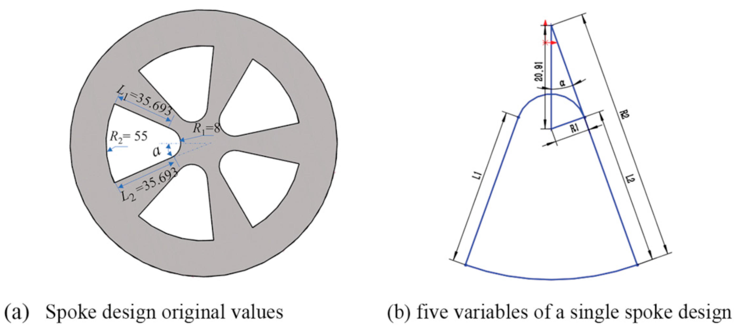
Figure 10: Schematic diagram of the five design variables of a single spoke design. Reproduced from Ref. [85] under the Creative Commons Attribution (CC BY) license.
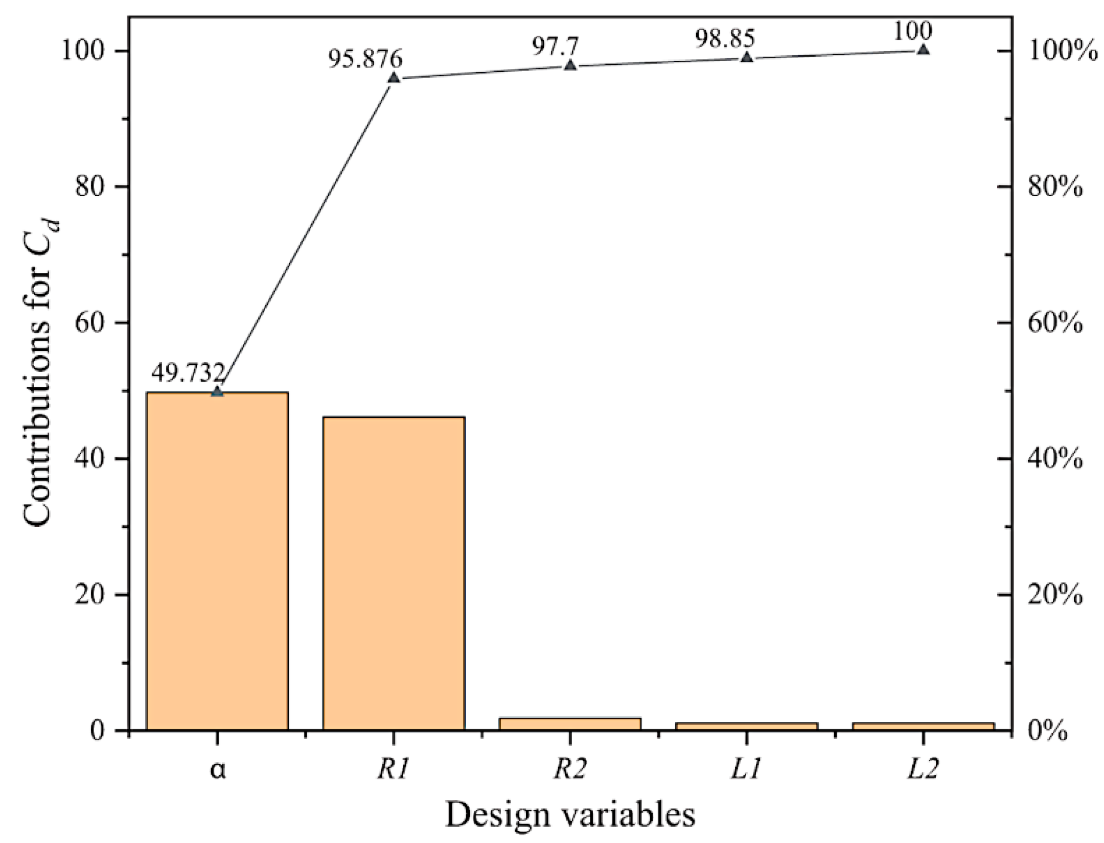
Figure 11: Contribution of different design variables for CD. Reproduced from Ref. [85] under the Creative Commons Attribution (CC BY) license.
Increasingly challenging fuel consumption and emissions targets have helped shed light on some debated aspects of wheel aerodynamics: one of these is ventilation resistance. This is an additional resistance to the aerodynamic drag: it is proportional to the aerodynamic torque around the wheels axis, resulting from the rotation of the wheels. Until now, the measurement of ventilation drag in full-scale automotive wind tunnels has been relatively uncharted territory. Link et al. [86] explained the procedure developed at the Research Institute of Automotive Engineering and Vehicle Engines in Stuttgart, later confirmed by BMW and Porsche, for measuring the ventilation drag in full scale wind tunnels. Vdovin et al. [87] pointed out how to modify the wind tunnel setup to measure ventilation drag and tested a series of wheels with different rim designs: each of the wheels was a five spoke, 17″ aluminum rim, with several interchangeable add-on parts. The experimental results highlighted that ventilation resistance depends on the wheel design: the rims with a thick outer radius, which are known to perform well in terms of aerodynamics drag force, also showed the best behavior in terms of ventilation drag. This configuration was found to be more efficient that a fully covered rim, in terms of overall drag. The authors also suggested extending the concept of ventilation resistance to all other parts of the vehicle that rotate in the air, such as the radiator fan. Hobeika and Sebben [88] further explored the link between ventilation drag and tyre geometry using the same method as in [84]. They pointed out that the ventilation moment, i.e., the aerodynamic resistance to wheel rotation, increases due to the addition of tyre details, particularly the lateral grooves. This increase is greater on the front wheel than on the rear wheel. They also called the CFD simulations accurate enough in predicting the impact of rain grooves on drag.
Shape and detail optimisation can be achieved with the help of unconventional methods. Erdem et al. [89] presented an aerodynamics optimization technique based on a Kriging model to simulate different front air dam geometries located under the front bumper of a reduced scale road vehicle. LES was used for an initial design-of-experiment (DoE) involving height geometric parameters for radial-basis-function of the front air dam, with a Sobol algorithm. Then, a multi-objective-genetic-algorithm was applied to the surrogate model, depending on the geometric parameters of the front air dam, in order to minimize CD under pressure constraints. The Sobol technique, driven by the Kriging model, was consistent with the wind tunnel tests, in terms of optimal air dam shapes, despite the relatively coarse numerical meshes used in CFD simulations. Yan et al. [90] used an improved efficient global optimisation algorithm to handle a drag reduction design, in four dimensions, of a full-scale vehicle combined with CFD, with the goal of reducing computational effort. In addition, data mining technology was used to shed light on the connections between design variables and aerodynamic drag. Wang et al. [91] studied not only the influence of wheel disc structure on CD but also the average convective heat transfer coefficient of brake discs by a multi-objective optimization design. Relying on mesh morphing technology, DoE sampling, surrogate model theory and NSGA-II (Non-dominated Sorting Genetic Algorithm) algorithm, the multi-objective wheel optimization design was carried out to obtain the Pareto frontier. The results obtained made it possible to reduce CD and the mass of the wheel and, at the same time, to increase the convective heat transfer coefficient of the brake discs.
4 Aerodynamic Drag Reduction by Active Flow Control
Since active flow control devices requires energy, their effectiveness can be evaluated by weighing the energy consumption against the benefits in terms of drag reduction. These devices are also used to achieve transition delay, lift enhancement, turbulence management, separation postponement and noise suppression. Active control schemes can be divided into predetermined methods or interactive methods, which, in turn, can be controlled by open- or closed-loop systems [92]. The former involves the introduction of steady or unsteady energy inputs without regard to the state of the flow field, while in the latter case the power input to the actuator is continuously adjusted based on measuring elements (sensors). A schematic of the multiple solutions is depicted in Fig. 12 drawing inspiration from [93,94,95].
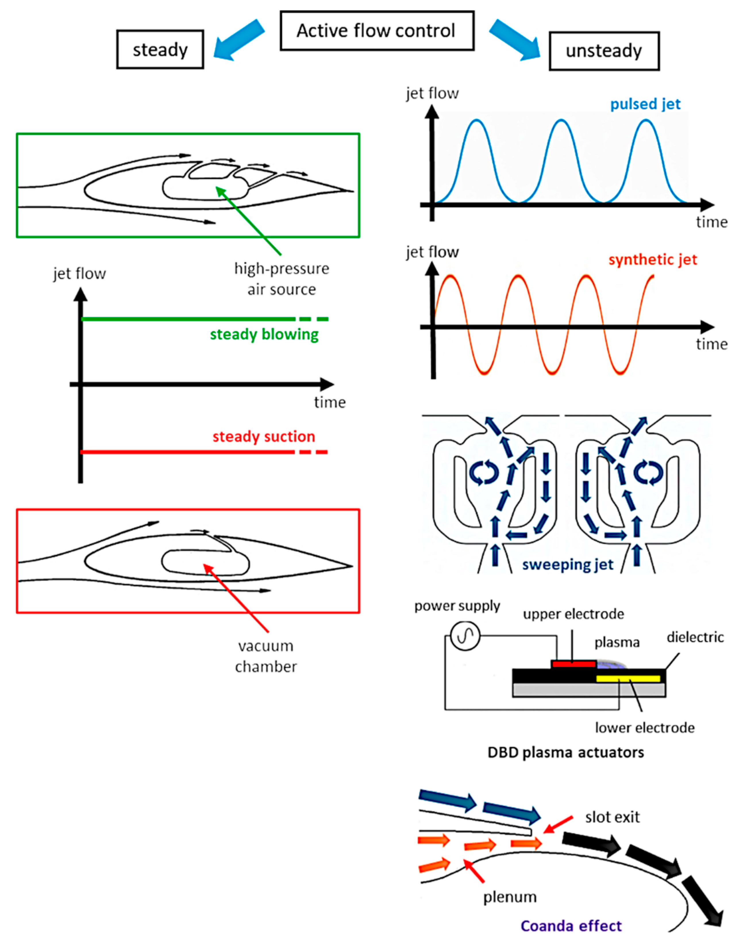
Figure 12: Schematic of active flow control options for drag reduction.
The reader is made aware that, although active flow control has potential for drag reduction in road vehicles, the challenges and limitations are significant [92]. Improvements in drag may be modest and not consistent with different driving conditions. Moreover, the complexity and energy consumption of the control systems may outweigh drag savings, especially at low speeds. Furthermore, actuators, controls and sensors should ensure reliability in a harsh operating environment.
4.1 Active Flow Control over Simplified Geometries and Blunt Bodies
4.1.1 Steady Blowing and Steady Suction
Mestiri et al. [96] experimentally investigated the influence of continuous blowing along the sharp edge between the roof and the slant of an Ahmed body (Fig. 13). The blowing slit length is equal to the model width and acts tangentially to the 25° slanted rear surface. The steady blowing widens the separated region on the rear window and hinders the development of longitudinal counter-rotating vortices appearing on the lateral edges: a reduction in CD of 6–10% can be achieved, depending on the blowing velocity. Nakashima et al. [97] demonstrated that a steady jet from a slit nozzle mounted in the same position as in [96] can be effective in changing the flow structure even under crosswind conditions (Fig. 14). Interestingly, the benefits of steady blowing remained for some time after the jets were stopped, opening up the possibility of intermittent flow control. A reversed Ahmed body with active flow control on the back end was analyzed numerically and experimentally by Tarakka et al. [98]: the steady blowing, generated by using a small compressor inside the body, is particularly effective when combined with optimization of the model front geometry.
As an alternative to blowing techniques, Rouméas et al. [99] used numerical LBM to simulate the effect of continuous suction on the upper part of the rear window of a simplified fastback car geometry. Suction creates a significant local depression on the separation line, which has the effect of reattaching the flow to the wall: the wake pressure losses decrease and, consequently, the related drag. Unfortunately, longitudinal vortices on the sides of the rear slant generate a higher total pressure loss. These discordant results suggest the need to develop a specific control system for longitudinal vortices: suction slots on the sides edges of the rear window should be able to prevent their generation; alternatively, a blowing device could cause them to break. Littlewood and Passmore [100] made the point: they carried out an extensive experimental campaign on steady blowing to recover pressure in the wake region of a squareback style simplified vehicle. Different blowing angles on the roof trailing edge of a Windsor model were considered: the only configuration that can decrease the overall drag deflects the upper shear layer downward, reducing the wake size and the velocities observed in the vortex structures located near the base surface. The energy saving due to drag reduction is greater than the energy consumption caused by the blowing device: however, the large mass flow rate required limits the applicability of the technique and leads to the exploration of different systems, such as pulsed jets.
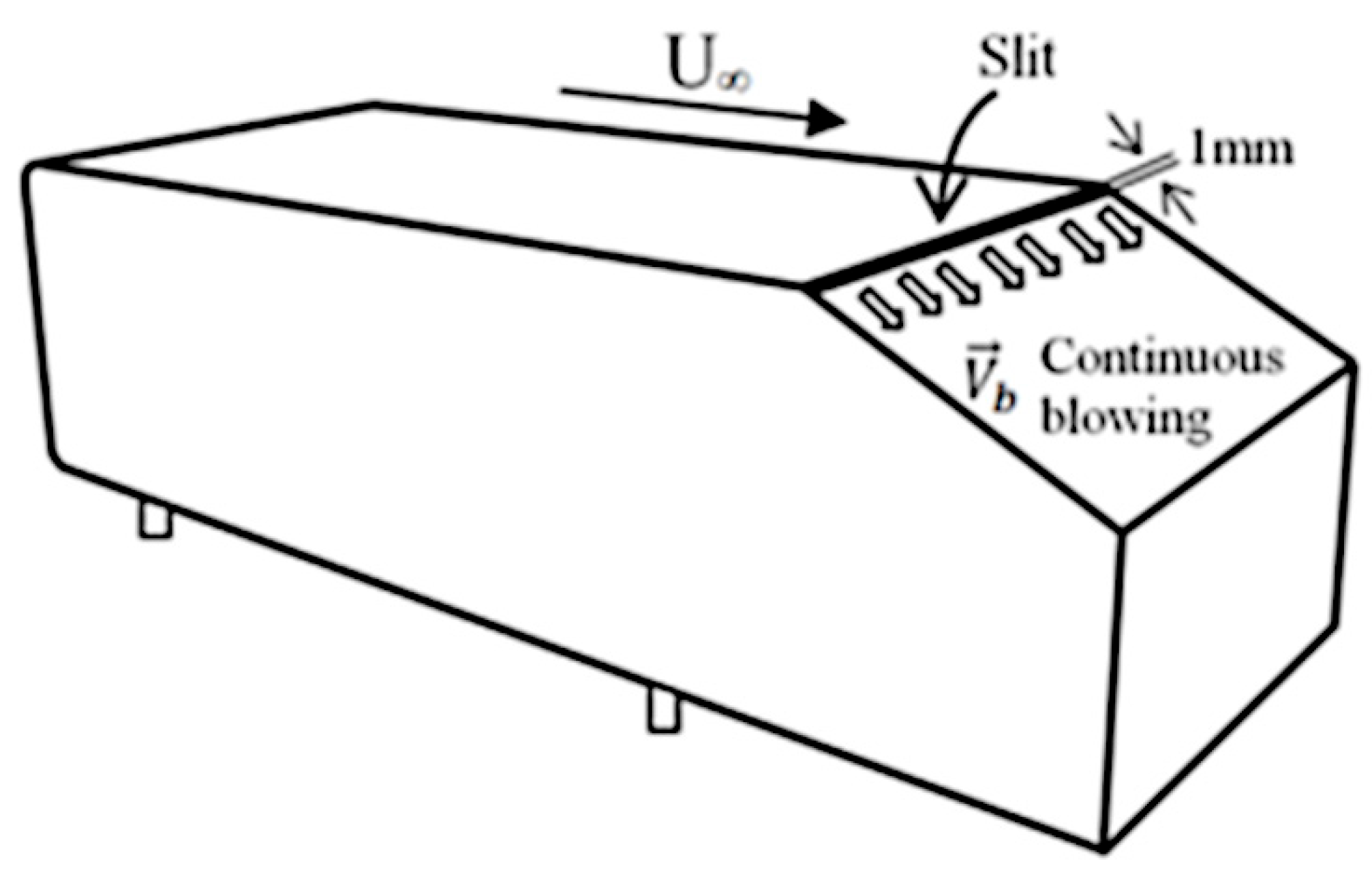
Figure 13: Control device used by Mestiri et al. (2014). Reproduced from Ref. [96] under the Creative Commons Attribution-NonCommercial (CC BY-NC 4.0) license.
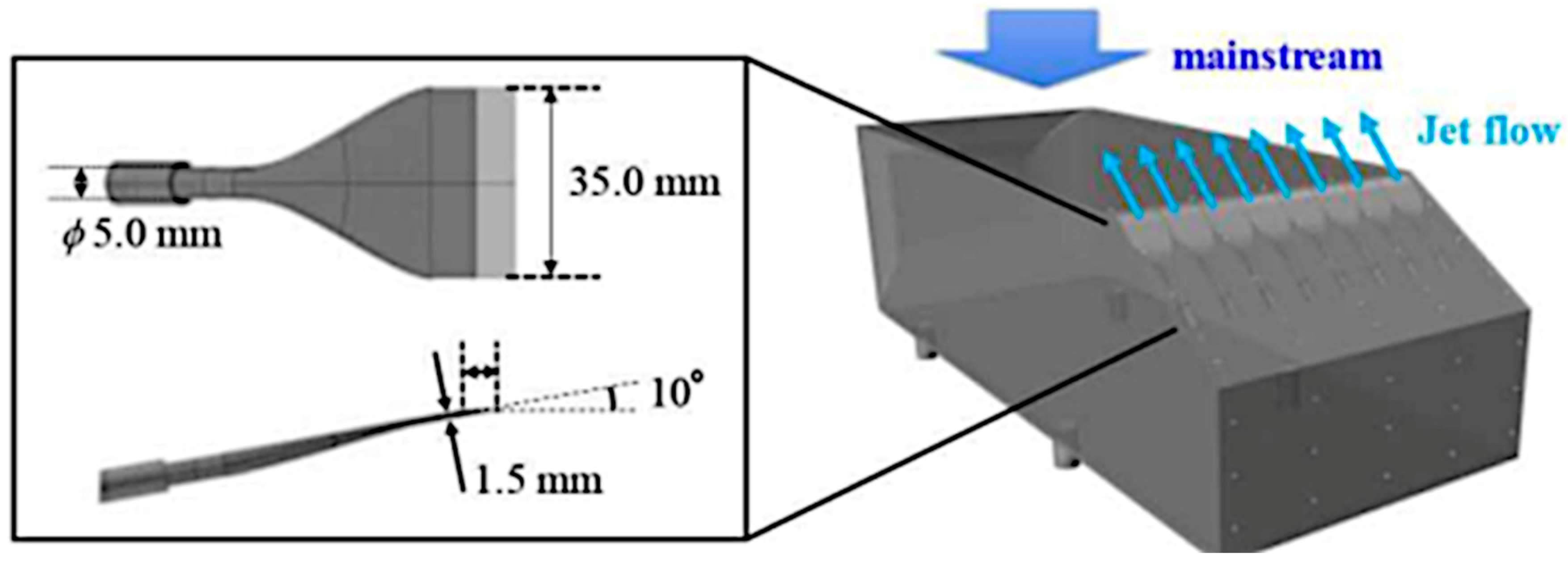
Figure 14: Control device used by Nakashima et al. (2020). Reproduced from Ref. [97] under the Creative Commons Attribution NoDerivatives (CC BY-ND 4.0) license.
Experimental testing, LES, and reduced order modelling were used by Östh et al. [101] to assess the impact of pulsed jets on drag reduction in a square back Ahmed body. Periodic, high-frequency blowing from a very small slit was applied on all edges at the base of the bluff body. Pulsed jets may affect the shear layer mixing, momentum balance of the wake region and thus the rear pressure. Aerodynamic drag control using pulsed jets was also tested in a wind tunnel by Gilliéron and Kourta [102]. Jets actuators, located on the top of the rear slant of an Ahmed body, were fed with different pressure values (from 1.5 to 6·105 Pa) and worked at different frequencies (from 10 to 550 Hz). The largest drag reduction (−20% compared to the case without flow control) was obtained for a frequency of 500 Hz and the lowest pressure supply. This result is accompanied by a large change in the flow topology in proximity of the rear slant, as evidenced by the PIV technique: control inhibits transverse development of the longitudinal structures coming from the rear sides of the model and shifts their centre downstream, leading to lower values of vorticity.
Another line of research deals with zero-net-mass-flux jets, obtained by the alternate combination of blowing and suction, often referred to as “synthetic jets” [103]. Theoretically, “a synthetic jet is produced by the interactions of a train of vortices that are formed by alternating ejection and suction of fluid across an orifice so that the net mass flux is zero. It is formed entirely from the working fluid of the flow system in which is deployed. Consequently, it can transfer linear momentum to the flow system without net mass injection across the flow boundary”.
Krajnović and Fernandes [104] employed LES to investigate the effects of sinusoidal jets on the near-wake flow of a two-dimensional blunt body geometry. The boundary layers on the upper and lower surfaces separate at the rear end of the body, forming two unstable and interacting shear layers that result in vortex shedding: hence, two jet slots were applied. The idea behind it is to delay the flow instability in the shear layers, so as to redistribute the low pressure in the wake and increase the pressure in the base area. According to LES predictions, a reduction in drag of about 11% could be achieved, but the effectiveness of this type of control on three-dimensional bodies has yet to be tested. Han et al. [105] confirmed the results reported in [104] for two-dimensional models, despite the different numerical method based on Partially-Averaged Navier–Stokes equations.
Cui et al. [106] relied on LES to compare steady blowing and synthetic jets on an Ahmed body. Different jet positions, jet directions and driving frequencies were investigated, and the main finding is that synthetic jets provide greater drag reduction than steady blowing (9% vs. 3%). This is because excitation with a certain frequency can dominate the vortex shedding process: consistently with [104], the instability of the shear layers is suppressed so that the flow remains attached to the rear slant, thus leading to increased pressure in the base area (Fig. 15).
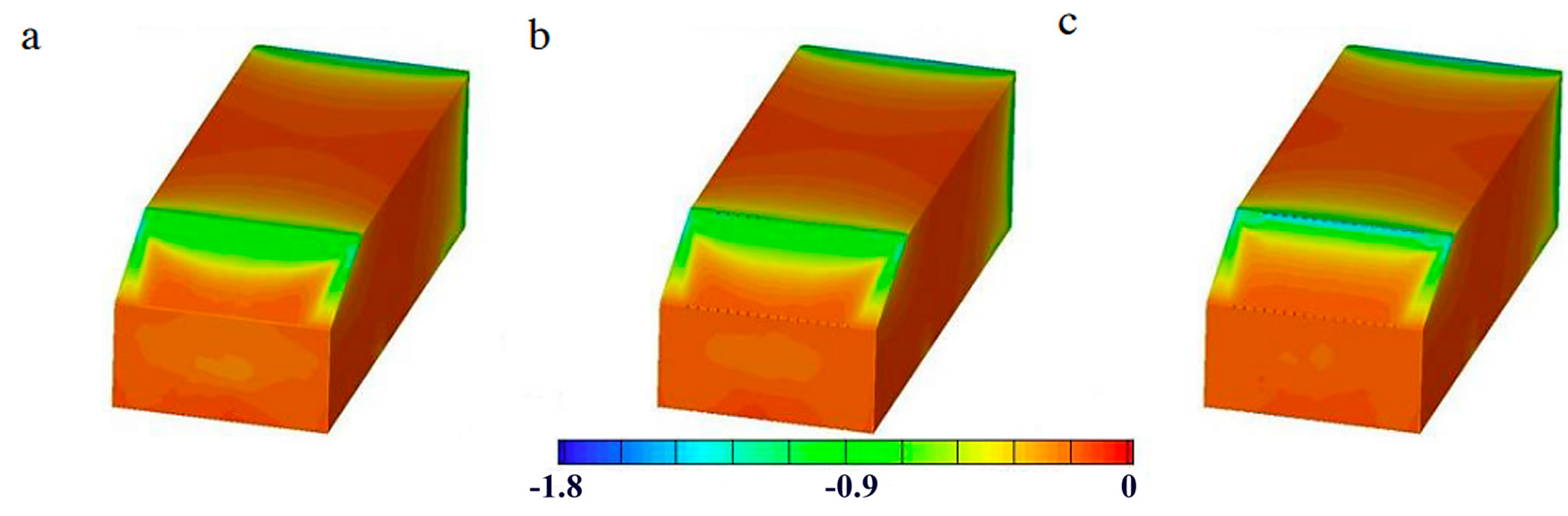
Figure 15: Pressure coefficient distributions: (a) natural flow; (b) steady blowing; (c) synthetic jets. Reproduced from Ref. [106] under the Creative Commons Attribution-NonCommercial-NoDerivatives (CC BY-NC-ND 4.0) license.
Another type of active flow control that deserves attention is steady or pulsed microjets: despite the small size, the limited amount of mass flow and momentum involved, and the low energy requirement, they can produce significant changes in flow characteristics.
McNally et al. [107] applied microjets, with a diameter between 0.4 and 1 mm, to the top and sides of the rear surface of a flat-back blunt model (Honda simplified body), in both normal and tangential directions. Different injection locations and orientations, jet diameters and blowing ratios were studied using both LES and PIV approaches. The microjet control was found to be effective when implemented upstream of separation, with a wall-normal blowing orientation. Moreover, the small perturbation caused by the microjets allowed the wake to become symmetric compared with the baseline configuration, thus resulting in a shift of the low-pressure region away from the rear surface of the model. All this led to a reduction in drag of up 2.5%, achieved when normal blowing occurs simultaneously at the top and side arrays.
Better results, in terms of drag reduction, were previously obtained by Aubrun et al. [108] by equipping a 25° slanted Ahmed body with an array of steady microjets downstream and near the separation line between the roof and the slanted rear window. The array consists of more than 50 holes with a diameter of 0.4 mm; ejection direction is normal to the wall. Microjets were proven to be very effective in controlling the rear separation bubble, resulting in a reduction of drag from 9 to 14%, depending on the Reynolds number: for lower blowing rates, the separation is delayed; for higher flow rates, the separation is completely suppressed. Furthermore, the flow field in the near wake of the body acquires a more symmetrical topology, in agreement with [107].
In contrast to steady microjets, Joseph et al. [109] focused on the effects of pulsed microjets on the wake of a three-dimensional Ahmed body. When located upstream the recirculation bubble over the rear slant of the model, they can reduce CD by up to 10%.
Fluidic oscillators can also be used for active flow control. They create sweeping jets at different frequencies without moving parts, but exploiting the inherent instability of the fluid: in other words, they convert a steady pressure input into a spatially oscillating jet. They typically consist of an air supply, mixing chamber and/or feedback channels, depending on the type of geometry [110]. Khan et al. [111] measured a maximum drag reduction of around 4% by placing a single sweeping jet actuator at the base of a square-back Ahmed body. The actuator was installed in mid-plane position to suppress the wake asymmetry that otherwise governs the flow structure behind the body. Metka and Gregory [112] did better than in [111], with a drag reduction of nearly 7%, thanks to a spanwise array of fluidic oscillators located at the roof-slant interface of a 25° Ahmed body. PIV measurements put in evidence that separation control on the rear slant surface is the key: sweeping jets increase mixing with the outer flow and attenuate the strength of the spanwise structures shed from the roof. In addition, the authors pointed out the advantages of this type of active flow control over passive VGs, such as the lack of drag penalty associated with additional projected area and the minimal aesthetic impact.
Active flow control can also cover smaller scales thanks to dielectric barrier discharge (DBD) plasma actuators. These have been studied over the years to improve aerodynamic efficiency in many different fields, including automotive. They are lightweight, with a simple structure, require no holes or cavities, and are fully electronic, with a very fast time response. By applying a high-voltage alternating current signal (in the range 5–50 kV peak and frequencies between 1 and 100 kHz) through a pair of electrodes, molecules in the surrounding air are ionized and tangentially accelerated through the electric field by electrohydrodynamic interaction. Of note is that DBD plasma actuators require low input energy and generate limited temperature increases. These devices can modify the boundary layer, delay laminar-turbulent transition and prevent flow separation [113]. Kim et al. [114] implemented a DBD plasma actuator at the front edge of the 25° slanted surface of an Ahmed body, varying its spanwise length and applied voltage. The experiments revealed that drag can be reduced to a maximum of 10%, at the freestream velocity of 10 m/s. In fact, with the actuation, the flow remains attached to the slanted surface due to the additional streamwise momentum, thus leading to a significant base pressure recovery. It must be said that this control is not energy efficient in a laboratory-scale experiment, but it is reasonable to think that it would improve if a real-scale vehicle were considered.
The Coandă effect can be described as the tendency of a moving fluid to adhere to a surface and flow along it. Indeed, it is a fairly general term, valid for a variety of conditions. In active flow control applied on blunt bodies, the Coandă effect ensures that the fluid jet emerging from an orifice follows an adjacent curved surface and entrains fluid from the surroundings. It occurs for both laminar and turbulent flows, but since entrainment is typically orders of magnitude stronger in the latter case, the Coandă effect is best exploited in turbulent flows [115].
Geropp and Odenthal [116], with support from Daimler-Chrysler AG, experimentally investigated a Coandă blowing method on a 1/5 scale simplified car body, similar to the Windsor model. Blowing slots were applied on the upper and the lower edges of the back surface, whereas suction slots were placed on the front surface to draw in air from the ambient. The system consists of several components that connect the inlet and the outlet slots, such as the front chamber, the flow rectifier and the rear chamber. The flow is accelerated inside the model by a blower and then ejected tangentially into the dead water behind the car. Both jets, remaining attached on the back surface due to the Coandă effect, generate an increase in base pressure, thus leading to a total drag reduction of about 10%. The authors clarified that the method could be effective for a real-world automotive application provided that the compressor power for active flow control is less than the engine power saved through drag reduction. Momentum and energy equations suggest that this condition is satisfied with moderately high blowing rates.
The impact of a Coandă jet on the wake of a square-back Ahmed body was numerically assessed in [51]. The control was installed on the upper edge of the rear surface. The results of URANS simulations clearly showed that the recirculation region in the wake can be eliminated by increasing the jet velocity to 1.5 times the freestream velocity, producing a 50% drag reduction compared with the baseline model. Shear layers detached from the model side walls are entrained by the wall jets and a very rapid pressure recovery occurs downstream of the body. This active drag reduction technique has proven to be more effective than the passive control devices investigated in the same paper, as documented in Section 3.1.2.
The research by Li et al. [117], born from a partnership between university and automotive industry, combined pulsed jet technology with the Coandă effect. A blunt-edged Ahmed body was equipped with actuator slits at all four trailing edges, and the jets were guided by Coandă surface deflectors. Two control systems (open- and closed-loop), founded on base pressure measurements, can provide 22% drag reduction in all classes of control laws considered.
4.2 Active Flow Control over Realistic Models and Production Vehicles
Research on active flow control is vibrant and rich in proposals, but, to the authors’ knowledge, most of the technologies tested on blunt bodies have not become mature enough to be transferred to complex geometries, and even more so, to production vehicles. However, in June 2025, Mercedes presented the full-electric Concept AMG GT XX, a “high-tech lab on four wheels” that previews the technology for future generations of AMG cars. Among the numerous aerodynamic solutions applied to the vehicle, there is an active flow control technique by means of DBD plasma actuators. As described on the official Mercedes AMG Official Site (© 2025 Mercedes-AMG GmbH, 2025), the electric plasma actuator is used to create a targeted flow separation on a body curve at the rear, thus reducing drag by wake control. Further examples of active flow control applications on complex models and full-scale vehicles are outlined in this section.
Lee [118] numerically tested an air jet wheel deflector to reduce vehicle aerodynamic drag. Replacing a conventional wheel deflector, this active flow system injects air perpendicular to the freestream flow, creating a kind of air curtain that deflects the main flow away from the tyre. Results of the LBM simulations on a Fabijanic’s model equipped with wheels and wheelhouses were encouraging: as the air jet speed increases, the mass flow rate to the wheelhouses is significantly reduced and the formation of stagnation pressure is delayed at the tire surface, with a beneficial reduction in tyre drag. In short, the air jet deflector reduces vehicle drag by 6.4% when the jet speed is equal to the vehicle speed, which is better than 3.6% drag reduction with the conventional wheel deflector. Energy calculations reported by the author also ensure that the jet deflector is efficient under most operating conditions. The energy balance computed by the author guarantees the efficiency of the jet flow under most operating conditions.
Baek and Lee [119] chose the DrivAer estate model to evaluate the potential of continuous blowing in reducing vehicle aerodynamic drag. A slot was created at the end of the roof and another at the C-pillar, so that air was injected tangentially to the respective surfaces. Steady RANS simulations, with SST k-ω turbulence model, were run at different blowing speeds, from 20 to 100% of the freestream velocity. By lowering the total pressure loss at the rear of the vehicle, a maximum drag reduction of approximately 7.5% can be achieved for simultaneous roof and lateral blowing. Moreover, the authors claim that drag can be reduced by up to 6% while maintaining an energy efficiency > 1, defined as the ratio of energy saved by blowing to energy used by blowing. On the contrary, the outcomes of the experimental research conducted by Heinemann et al. [120] on a 1:4 Volkswagen New Beetle model are not very promising. The issue is that active flow control has to deal with fluctuations in lift and drag, due to the highly rounded rear geometry. Finding a suitable location for the flow control devices was not easy: steady air jets were made to exit from thin slots over the width of the rear window, in three different configurations (labelled as “top normal”, “bottom normal” and “bottom tangential”). Measurements using laser doppler anemometry and oil flow visualizations indicated that active flow control affects the recirculation area above the rear screen, but has minimal impact on the C-pillar longitudinal vortices. The air jet above the rear window forces early detachment of the flow, resulting in intensification of the recirculation area behind the model, increased CD and reduced lift. Instead, the air jet below the rear window, directed perpendicularly to the surface, has an opposite effect on drag and lift. Also, the air jet in the same position, but directed tangentially upward to the model’s roof can reduce lift without affecting drag. In brief, this steady active flow control is not very effective in reducing drag when applied to a realistic car model.
Eulalie et al. [121] tested a pulsed jet system mounted on the top and sides of the rear window of a BMW X5 prototype. Despite the large number of considered flow control parameters (jet angle at the spoiler and deflectors, jet frequency and location, blowing flow rate), the improvements in drag for the best configuration are limited, up to 2.5%. Although pulsed jets provide additional momentum at specific frequencies in the top shear layer, the pressure distribution is dominated by the vortices close to the bottom of the tailgate. For this reason, it is recommended to focus on flow control in the bumper region, despite the awareness that wind tunnel results are highly dependent on the shape of the SUV.
5 Active Aerodynamic Systems for Drag Reduction of Road Vehicles
As explained in [12], active aerodynamic systems consist of moving aerodynamic elements and appropriate control devices. They can adjust some aerodynamic characteristics based on vehicle speed, acceleration, yaw rate, steering angle, temperature of definite components, brake pressure, and so on. Modification of vehicle geometry can balance the conflicting needs that arise under different driving conditions in terms of comfort, safety, performance and fuel economy. Since most of the active aerodynamic devices are derived from motorsport, their purpose is not limited to reducing drag, but also includes reducing lift or increasing downforce. Accordingly, road cars that benefit from active aerodynamics devices are usually expensive, high-performance vehicles or hypercars. In other words, the advantages in terms of performance, handling and stability come at a price and engineering complexity that are not compatible with mid-range vehicles, which are designed to be economical, robust and reliable for a long time, despite high usage. High costs for the development and implementation of active systems are the main obstacle to wider market penetration [122].
The Koenigsegg Agera and Bugatti Veyron, for example, can adjust the ride height and angle of attack of the rear wing according to different operating conditions. High-speed and high-downforce settings are available for the Agera, as depicted in Fig. 16. The Veyron has four operating modes depending on speed (Fig. 17): noteworthy is the case where, when the brake pedal is pressed, the spoiler lifts up and deploys at 55° (labelled “braking”).
In 2017, Lamborghini developed an active aerodynamic system, known by the acronym ALA—Aerodinamica Lamborghini Attiva—[123]. A computer controls both the flap-equipped front air splitter and the rear wing, to optimize acceleration, braking, cornering, and top speed. Air flows above and below the splitter to increase front downforce when the flaps are closed. Instead, when the flaps are open, the flow is entirely directed under the car, reducing downforce and, consequently, induced drag. The rear wing can generate considerable downforce, but also drag: when downforce is not needed, the angle of attack is typically reduced. The ALA system relies on a different physical principle to pursue the low-drag mode. The wing is hollow and its lower surface is pierced with venting holes: by opening flaps, a jet of air flows through the wing cavity before blowing the wing underside, thus eliminating the pressure differential between the upper and the lower surfaces (Fig. 18). Note that blue streamlines in Fig. 18 indicate the air passage through the internally ducted wing pylons. Also in 2017, General Motors registered a patent on a complex active aerodynamics system, for the purpose of reducing drag and wind noise, preventing undesired lift and instability at high speed, achieving downforce to improve vehicle traction and cornering. Adjustable devices controlled by the system included a spoiler, an air dam, a shutter with moveable louvers, a specialized wing, an airfoil and a dive plane [124]. The vehicle in question is the Corvette Stingray.
Other innovative solutions in terms of active aerodynamics are installed on the Mercedes-AMG GT R [125]. Concealed in the front underbody is a carbon fibre profile that, by moving 40 mm downward, can reduce the frontal lift and drag and increase the cooling of the engine and brakes. In fact, when the profile is electrically extended, the radiator air outlet guides the flow towards the rear diffuser and the braking-duct-diffusor on the underbody increases its depth directing clean cold air to the brakes (Fig. 19). Moreover, the active air management system (AAMS) can open or close the vertical louvers located behind the front grille, depending on the engine cooling needs (Fig. 20). The louvers are normally closed to reduce drag and front lift; they open only when predefined components have reached a predetermined temperature and the heat exchangers require the maximum amount of cooling air. In addition, the rear wing can be adjusted manually in a range of 10°.
The AMG GT 4-Door Coupé represents a step forward [126]: the concept of “cold air only when needed” has been reinforced in the AAMS and combined with the active rear spoiler. In fact, the vertically louvers, normally closed but opening quickly in case of high cooling demand as explained above, can provide a fast response to the heat exchangers by adjusting their direction of rotation. Airflow to the “centre” depicted in Fig. 21 leads to improved aerodynamic performance: first, a reduction in drag (ΔCD = −0.008) but also a decrease in front lift with a limited increase in rear lift. As for the active rear spoiler, it moves to different height levels, from 0 to 182 mm, in 5 positions, to reduce drag or increase downforce when required, depending on the selected driving program and vehicle parameters.
It is clear that the active features can effectively interact to meet the requirements of both road use (i.e., high aero efficiency with a low CD) and track use (i.e., high downforce level) to boost racetrack performance. However, not only high-performance vehicles can benefit from active aerodynamics [127]. Indeed, companies such as Magna have been developing active aerodynamic systems since 2010 and, after a decade, many active devices are available on many vehicles, among which Dodge Dart, RAM 1500, Mercedes Benz E-Class: grille shutters, air deflectors, underbody, front wheel deflectors, spoilers, and rear diffuser.
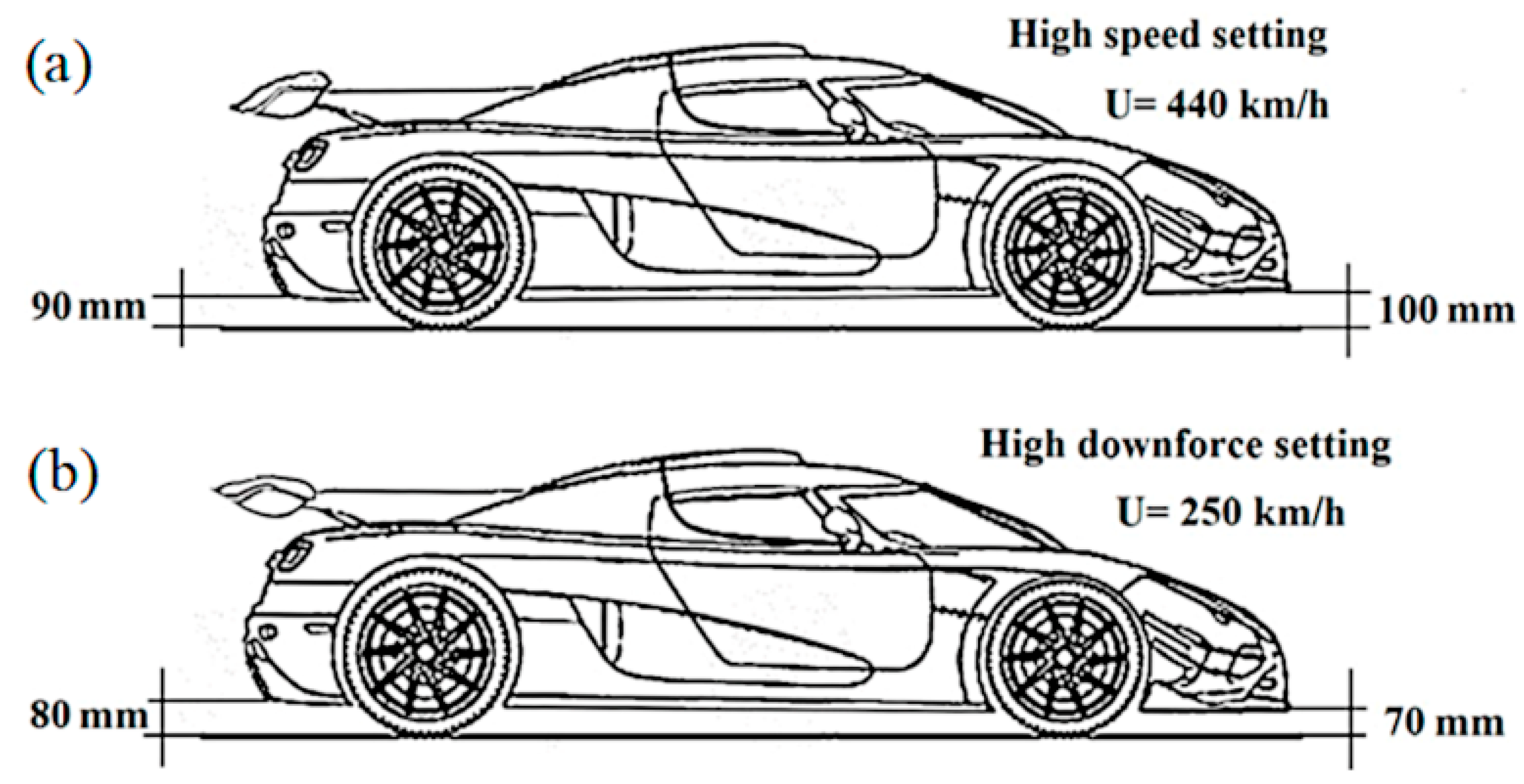
Figure 16: Koenigsegg Agera and its settings: (a) high speed; (b) high downforce. Reproduced from Ref. [12] under the Creative Commons Attribution (CC BY) license.
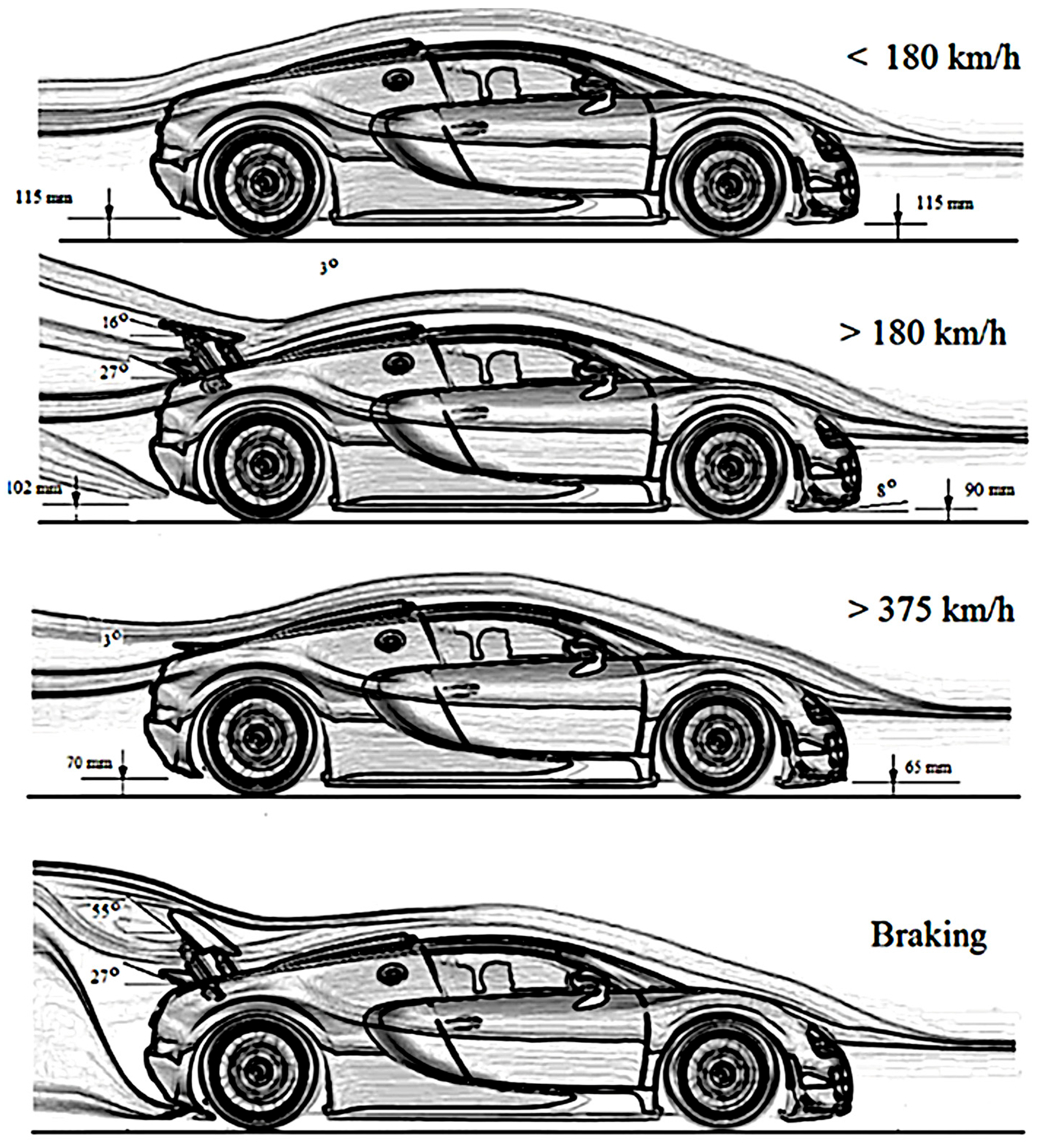
Figure 17: Bugatti Veyron operating modes. Reproduced from Ref. [12] under the Creative Commons Attribution (CC BY) license.
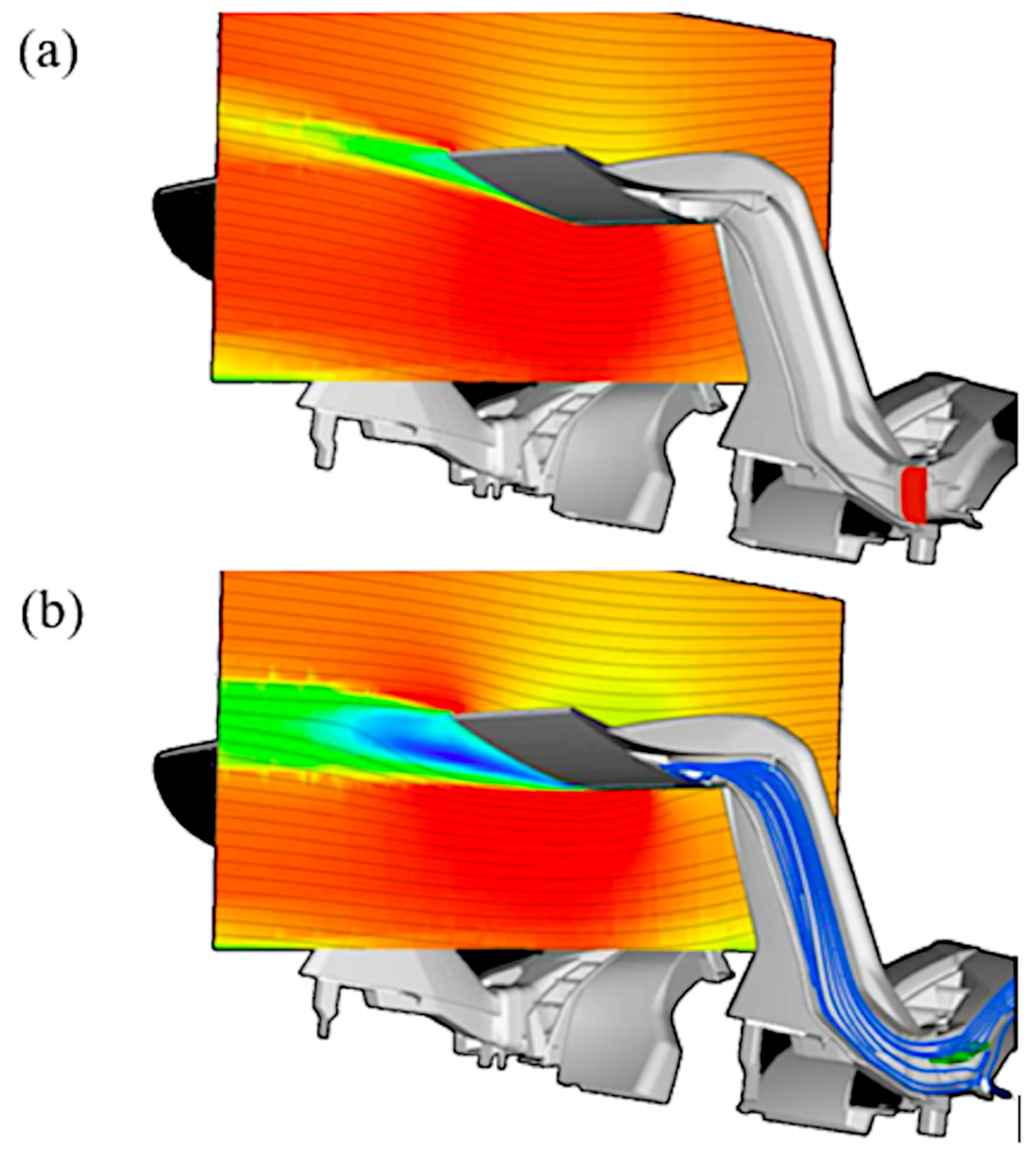
Figure 18: CFD qualitative representations of ALA operating principle: (a) closed flap/high downforce “off” mode; (b) open flap/lower downforce and lower drag mode. Reprinted with permission from Reference [123]. 2017, Lamborghini.
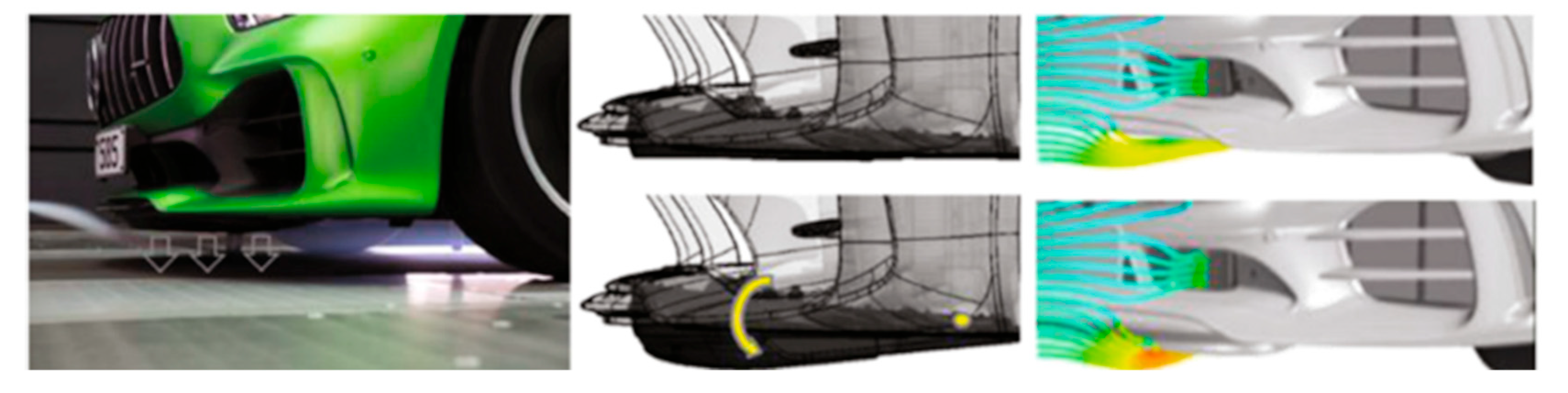
Figure 19: Aerodynamic profile in the underbody of the Mercedes-AMG GT R. Reprinted with permission from Reference [125]. 2017, Gustavo Estrada.
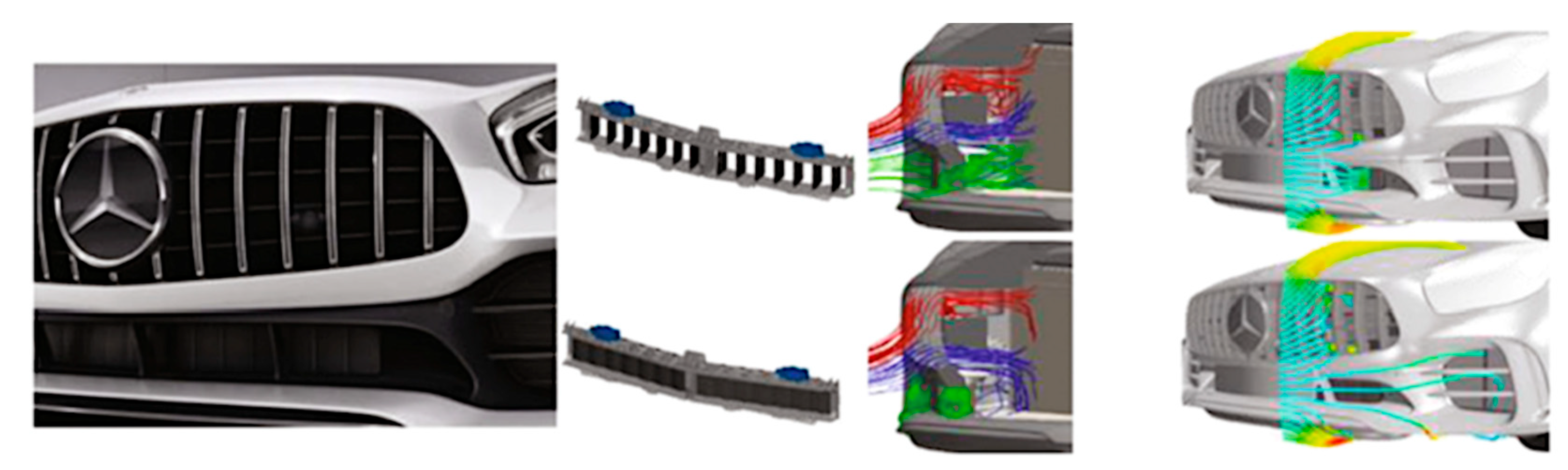
Figure 20: Electronically controlled frontal louvers of the Mercedes-AMG GT R. Reprinted with permission from Reference [125]. 2017, Gustavo Estrada.
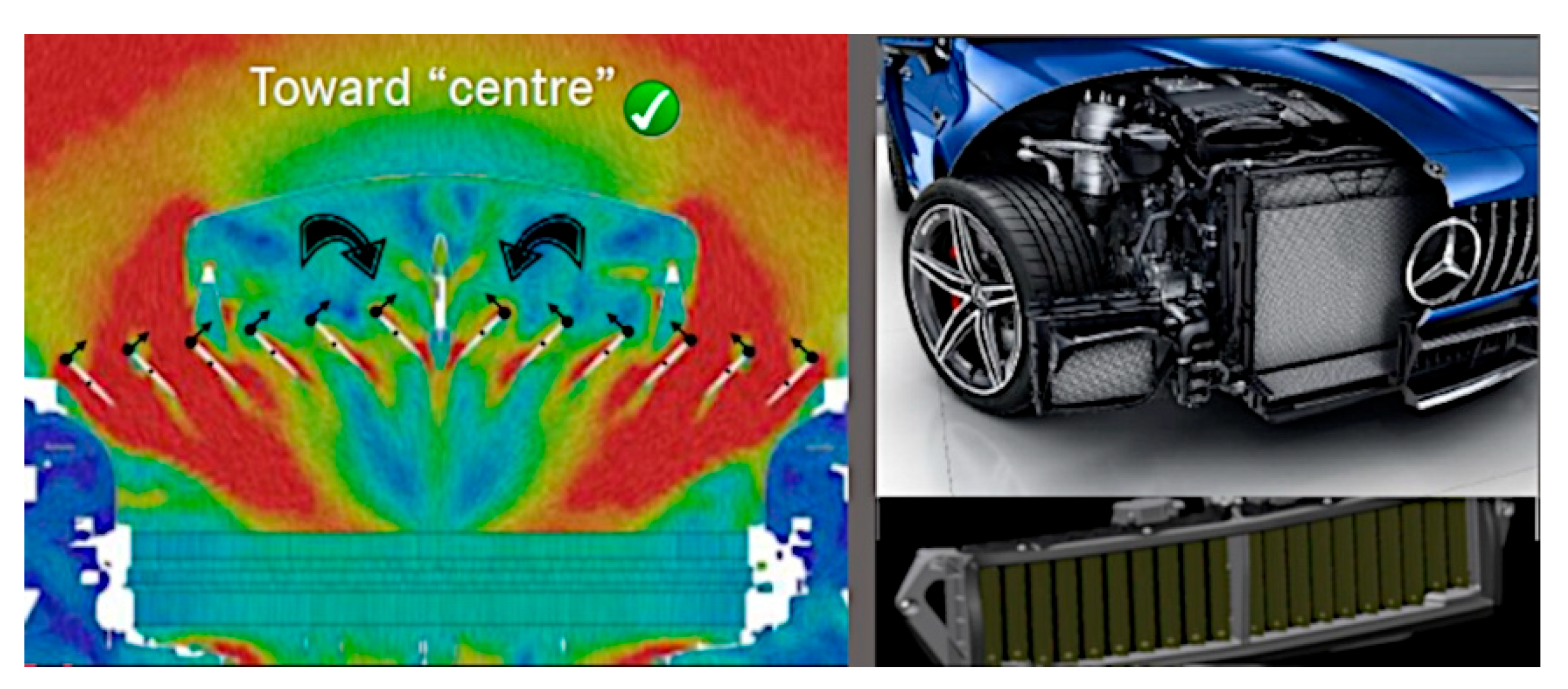
Figure 21: Motor controlled frontal louvers of the Mercedes-AMG GT 4-Door Coupé with qualitative representation of the flow field. Reprinted with permission from Reference [126]. 2019, Gustavo Estrada.
6 Electric Vehicle Aerodynamics
The different core concepts at the base of battery EVs and traditional internal combustion engine (ICE) vehicles have a strong influence on many aspects of the overall design. Since the limited range is probably the main weakness of EVs, fuel efficiency should be the main goal of engineers and designers: mass, aerodynamic drag and rolling resistance must be minimised, while at the same time maximising engine/motor and transmission efficiencies.
Rolling resistance (
As evident from Eq. (1),
In order to minimize the drag area and extend vehicle range, EVs should benefit from a series of technological devices and recent aerodynamic innovations to manage external flows and thermal management internal flows. A comprehensive review of recent advances in the modern vehicle thermal management was provided by Wang et al. [130]: a section of the survey is specifically dedicated to EVs.
Internal flows of EV are primarily involved in battery thermal management (cooling and preheating): in fact, the battery pack must operate within a certain temperature range to ensure an adequate level of performance and prevent aging, thermal runaway and capacity fade. For example, the common operating temperature of lithium-ion batteries is usually between 15°C and 40°C [131]. Moreover, a cooling system is required for electric motors, gearbox and power converters: for instance, silicon carbide (SiC) bare dies developed by Bosch for the automotive industry are designed for a maximum temperature of 175°C and 100 h at 200°C [132]. Last but not least, the heating, ventilation, and air conditioning system, often integrated with the battery thermal management system, is responsible for regulating the cabin temperature. In older and cheaper EVs, heating is done using resistive heaters or positive temperature coefficient heaters, while cooling is carried out with a conventional air-conditioning system with an electric compressor. Depending on the difference between the outside temperature and the desired cabin temperature, range losses of up to 50% can be observed [133]. Modern EV make use of a reversible heat pump [134] which is able to supply cooling and heating capacity more efficiently.
Configuration of cooling flows or EVs has been under study for years. Xu and Zhao [135] numerically investigated the effect of air-inlet and air-outlet patterns and battery positions on the EV aerodynamic performance. Selvan et al. [136] explored the use of an air dam to create a local high-pressure area used to direct cooling airflow to the battery; moreover, fins were employed at the base of the battery to improve convective heat exchange.
In addition to thermal management, the external aerodynamics of EVs also presents complex challenges. In the early stages of development and placing on the market, many EVs were derived from ICE cars, thus not exploiting the full potential of a dedicated EV platform. Li and Zhou [137], taking inspiration from the so-called “shape optimization” design process, started from a very streamlined three-dimensional body (CD = 0.06) and reached step by step the final vehicle shape (CD = 0.19). This design procedure allows for achieving lower CD compared to the “detail optimisation” technique, which involves the modification of small elements of a predefined shape. It should not be overlooked that aerodynamics can assist in energy recovery in high-performance and track-oriented road cars: Georgiev et al. [138] developed an open-loop strategy to maximize energy recuperation during braking from high speeds by means of the orientation of the active rear wing, the brake balance and the blending between regenerative and friction braking.
Unlike the early EVs, recent concepts and production cars designed starting from scratch are characterised by technical aerodynamic solutions that set a benchmark for the sector. The Porsche Taycan (2019-present) is a production EV characterized by a CD value from 0.22 and a frontal area of 2.33 m2. This results in an effective drag area of 0.513 m2 [139]. In addition to the optimised basic shape, the vehicle benefits from passive and active aerodynamic devices (Porsche Active Aerodynamics). The headlights are housed within large air inlets, which guide the air curtain over the front wheel housings. The underbody is completely panelled, and the suspension links are fully covered and equipped with air ducts. The rear end of the vehicle takes advantage of an extremely wide rear diffuser, thus reducing both drag and lift. Measures in the area of active aerodynamics include the lower side air intakes at the front: cooling air flaps supplying two radiators are individually controllable. Also, the flow onto the brakes is controlled as required by the chassis control unit, via a brake air duct. The Taycan also has active aerodynamics at the rear: depending on the driving situation, the spoiler extends to three different positions and thus influences the car’s drag and rear lift. The air suspensions provide further aerodynamic opportunities: depending on the speed and the selected driving mode, a lower position is activated, which additionally reduces drag [139].
Mercedes-Benz in 2022 presented the Vision EQXX, a full-electric concept car with a permanently installed solar cell roof feeding the 12 V battery, which in turn supplies the infotainment system, the air blower, the LED headlights, and other auxiliaries [140]. It is a four-door sedan, but it does not have a traditional three-box design: the basic form of the body integrates the smooth dome of the passenger compartment and the water-drop-shaped rear end. The frontal area of 2.12 m2 [141] is less than that of the Mercedes Benz CLA. Considering a CD of 0.17 [142], the total drag area attains the very low value of 0.36 m2. The retractable rear diffuser deploys only at higher speeds; when retracted, it fits into the bodywork. The Vision EQXX is equipped with lightweight and low-rolling-resistance tyres, developed in partnership with Bridgestone. In terms of aerodynamics, these tyres have optimised sidewalls to match the covers mounted on the 20-inch forged-magnesium wheels [140]. The thermal-management system of the car is based on the “cooling on demand” approach. Only when cooling or air conditioning demand increases on hot days or when the heat pump is operating on cold days, the aero shutters system opens an additional air path (“active cooling” mode). The air guide connects the dynamic pressure zone at the front of the vehicle with the low-pressure zone on the bonnet: this enables highly efficient thermal management with minimal air resistance. With the shutters open, the CD value would increase by only seven points ΔCD = 0.007). In “passive cooling” mode, for optimising aerodynamic efficiency, the underfloor cooling plate uses external airflow along it and provides cooling of the electric drivetrain [140]).
The aforementioned Concept AMG GT XX (CD = 0.19), besides the DBD plasma actuators, is equipped with ventilating wheels, high-performance aerodynamic tyres, front air curtain to manage the front tyre wake, optimized side mirrors, active suspension system with dedicated ride height adjustment. The absence of a front ICE allows for an efficient racing-inspired cooling system with bonnet outlet. Also, EV platforms usually allow for an aerodynamically optimized underbody: the Concept AMG GT XX takes advantage of the Venturi effect, is fitted with an extended diffuser and deflectors directing air flow around rear wheels [143].
The key point is whether the results produced by research have translated into improved aerodynamic behavior of cars on the road, so as to reduce their carbon footprint. The International Energy Agency stated that global SUV sales grew by more than 10% between 2020 and 2021 [144]. In 2022, despite the worldwide car market contraction, SUV sales increased by 3% over 2021, accounting for 46% of global car sales and emitting nearly 1 billion tons of CO2 [145]. Above all, the growing market share of larger and heavier vehicles is undermining opportunities to mitigate the environmental impact of the world’s passenger car fleet, thus offsetting the benefits of the increasing shift to electric mobility [11]. In fact, both CD and frontal area of SUVs are inevitably larger than of a typical sedan. This, combined with the higher weight (about 200–300 kg more), results in about 20% more CO2 emissions and higher specific energy consumption [146]. Fig. 22 shows clearly that large SUVs are the most energy-intensive vehicle type. As reported by Cazzola et al. [146], even with an electric powertrain, SUVs are still paired with higher energy use per km (0.18–0.20 kWh/km) and larger battery packs (70 kWh), thereby raising the demand for critical minerals, compared to a small/medium car (0.14–0.15 kWh/km; 50 kWh). Fig. 23 compares three models available in both electric and gasoline versions based on an environmental damage index. Although the former (EV) has a lower environmental impact than the latter (ICE), heavier models cause more damage to the environment, regardless of the powertrain [147].
Research and investments in aerodynamic field do not lead to concrete improvements in terms of the environmental footprint of most cars offered by automotive market. If the goal is truly to make the private automotive sector more sustainable, reducing the prevalence of large, heavy vehicles like SUVs should be mandatory while encouraging smaller and lighter car designs. Vehicle size and form are primary variables, rather than secondary parameters to be optimized.
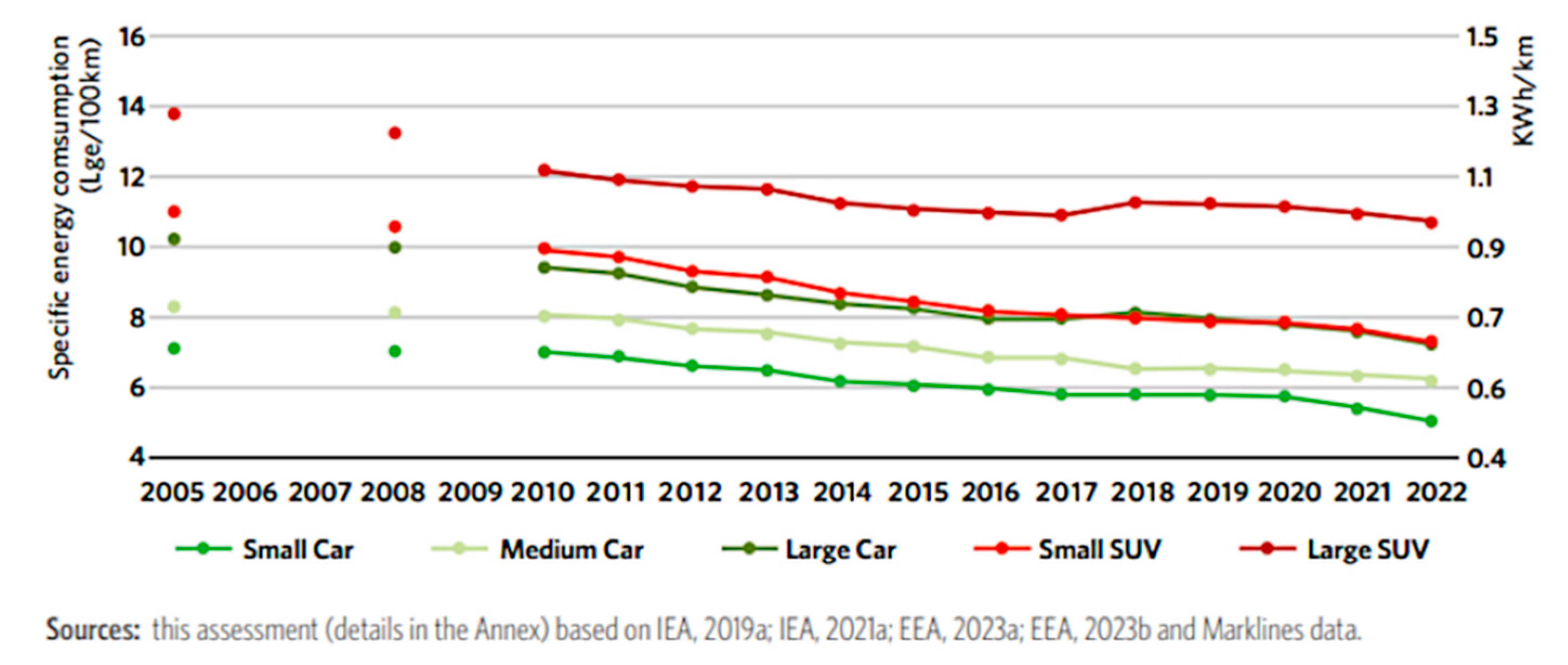
Figure 22: Global specific energy consumption by vehicle segment—Lge stands for liter of gasoline equivalent. Reprinted with permission from Reference [146]. 2023, Global Fuel Economy Initiative.
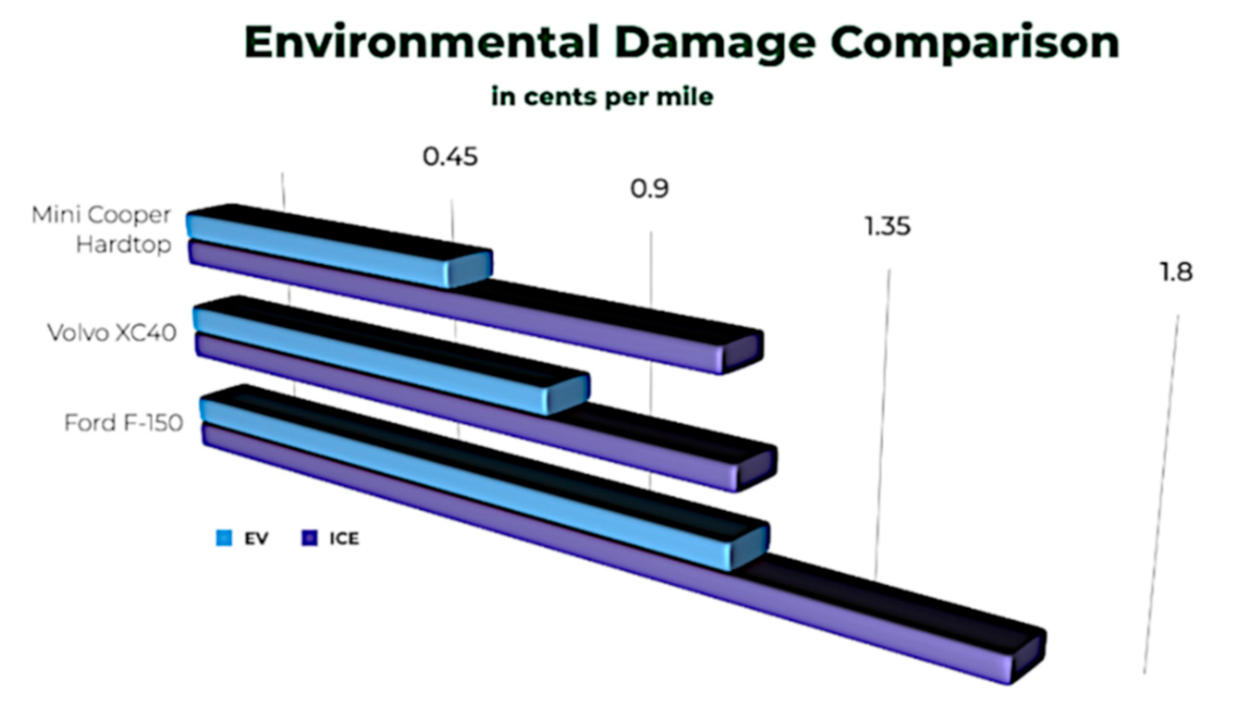
Figure 23: Environmental impact of three representative car models. Reprinted with permission from Reference [147]. 2023, American Council for an Energy-Efficient Economy.
The aerodynamic performance of the current vehicle fleet could be improved by reducing the drag area, thus lowering not only CD but also the frontal area. Passive and active flow control could help reduce CD by about 6–12% according to most of the applications covered in this review.
Nowadays, drag reduction in production vehicles is achieved almost exclusively through passive methods, such as vortex generators, cavities, boat tailing and tapering, underbody panels, rear diffuser, spoilers, air curtains for tyre wake mitigation, low-drag rims and tyres, and optimization of internal flows. Active flow control methods, e.g., steady blowing and suction, pulsed jets, synthetic jets, sweeping jets, microjets, plasma actuators, generally require further research and investigation. Aside from the complexity of implementing these systems, it is not always clear whether the aerodynamic energy savings resulting from active flow control devices exceed the energy required to power them.
The evaluation of active aerodynamics is very case-dependent and somewhat “incomplete” because of limited access data. Proper active aerodynamics finds predominantly application in high-performance and premium vehicles. Among the most significant devices are ride height adjustment via active air suspensions, active rear wings, spoilers, splitters and air dams, internal flows management by means of active grille shutters, movable louvers, cooling air flaps. It should also be noted that active flow controls and active aerodynamic devices require maintenance and service, increasing operating costs.
As regards reduction in frontal area, automakers should overcome the logic of short-term profitability, since SUVs are the most money-making models. On the other hand, lawmakers should “keep an eye” on the average size of fleet vehicles. The introduction of a cap on vehicle carbon footprint could limit the increase in vehicle size, for both ICE ones and EVs. Moreover, implementation of incentives is recommended to accelerate the market adoption of new technologies that improve cars’ aerodynamic performance. This study shows that we can design lightweight, low-drag cars: now we need to promote their commercial deployment to steer consumers in the right direction, helping to combat climate change. Efforts in aerodynamic research, both experimentally and numerically, in the development and implementation of complex solutions to reduce CD contrast with the crazy turn the automotive industry has taken by increasing the frontal area of road vehicles. “SUVisation” may even negate the benefits of electrification, in terms of reducing overall CO2 emissions, as recently emerged [148,149].
Acknowledgement:
Funding Statement: The authors received no specific funding for this study.
Author Contributions: The authors confirm contribution to the paper as follows: study conception and design: Umberto Ravelli, Silvia Ravelli; data collection: Umberto Ravelli; analysis and interpretation of results: Umberto Ravelli; draft manuscript preparation: Umberto Ravelli, Silvia Ravelli; revised manuscript preparation: Umberto Ravelli, Silvia Ravelli. All authors reviewed and approved the final version of the manuscript.
Availability of Data and Materials: The authors confirm that the data supporting the findings of this study are available within the article and properly referenced.
Ethics Approval: Not applicable.
Conflicts of Interest: The authors declare no conflicts of interest.
Nomenclature
| A | Area |
| AAMS | Active air management system |
| CD | Drag coefficient |
| CFD | Computational fluid dynamics |
| D | Drag |
| DBD | Dielectric barrier discharge |
| DDES | Delayed detached eddy simulation |
| DES | Detached eddy simulation |
| DoE | Design-of-experiment |
| EV | Electric vehicles |
| F | Force |
| ICE | Internal combustion engine |
| IDDES | Improved delayed detached eddy simulation |
| k | Turbulent kinetic energy |
| L | Length of the chord |
| LBM | Lattice Boltzmann method |
| LES | Large eddy simulation |
| m | Vehicle mass |
| MRF | Moving reference frame |
| NEDC | New European drive cycle |
| P | Power |
| PIV | Particle image velocimetry |
| rr | Rolling resistance |
| R | Radius |
| RANS | Reynolds-averaged Navier-Stokes |
| Rke | Realizable k-epsilon |
| SAE | Society of automotive engineers |
| SBES | Stress-blended eddy simulation |
| SST | Shear stress transport |
| SUV | Sport utility vehicle |
| URANS | Unsteady Reynolds-averaged Navier-Stokes |
| v | speed |
| VG | Vortex generator |
| VW | Volkswagen |
| WLTP | Worldwide harmonized light vehicles test procedures |
| α | Fillet angle |
| ε | Turbulent dissipation rate |
| ρ | Density |
| μ | Coefficient |
| φ | Slant angle |
| ω | Specific turbulent dissipation rate |
References
1. Hucho WH . Aerodynamics of road vehicles. 4th ed. Warrendale, PA, USA: SAE International; 1998. p. 918 [Google Scholar]
2. Barnard RH . Road vehicle aerodynamic design: An introduction. St Albans, UK: MechAero Publishing; 2009. [Google Scholar]
3. Auto Research Center . The effect of aerodynamic drag on fuel economy [Internet]. 2025 [cited 2026 Jan 7]. Available from: https://www.arcindy.com/effect-of-aerodynamic-drag-on-fuel-economy.html. [Google Scholar]
4. Nyoni E , Chigumba P . Aerodynamics and its role in enhancing fuel efficiency in automotive engineering. Int J Automob Eng. 2024; 5( 2): 32– 5. [Google Scholar]
5. Association of European Vehicle Logistics . WLTP, RDE and automotive emissions targets [Internet]. 2019 [cited 2026 Jan 7]. Available from: https://www.ecgassociation.eu/wp-content/uploads/2019/10/19.10-WLTP-briefing-paper-v3-Draft-v1-Web.pdf. [Google Scholar]
6. Boulouchos K , Sturm PJ , Kretzschmar J , Duic N , Laurikko J , Bradshaw A , et al. Decarbonisation of transport: Options and challenges. EASAC Policy Rep. 2019; 37: 1– 68. [Google Scholar]
7. Hackenberg U . Aerodynamics—Industrial espionage in the realm of nature. ViaVision, No. 06, July 2012. Wolfsburg, Germany: Volkswagen Group; [cited 2025 Feb 1]. Available from: https://www.vwpress.co.uk/assets/documents/original/17817-ViaVision06Aerodynamics.pdf. [Google Scholar]
8. Katz J . Automotive aerodynamics. Hoboken, NJ, USA: John Wiley & Sons, Inc.; 2016. [Google Scholar]
9. Connolly MG , Ivankovic A , O’Rourke MJ . Developments in drag reduction methods and devices for road vehicles. Appl Sci. 2025; 15( 17): 9693. doi:10.3390/app15179693. [Google Scholar] [CrossRef]
10. Larson L , Woodiga S , Gin R , Lietz R . Aerodynamic investigation of cooling drag of a production Sedan part 1: Test results. SAE Int J Passeng Cars Mech Syst. 2017; 10( 2): 628– 37. doi:10.4271/2017-01-1521. [Google Scholar] [CrossRef]
11. Cozzi L , Petropoulos A . SUVs are setting new sales records each year—And so are their emissions [Internet]. 2024 [cited 2026 Jan 7]. Available from: https://www.iea.org/commentaries/suvs-are-setting-new-sales-records-each-year-and-so-are-their-emissions. [Google Scholar]
12. Piechna J . A review of active aerodynamic systems for road vehicles. Energies. 2021; 14( 23): 7887. doi:10.3390/en14237887. [Google Scholar] [CrossRef]
13. Gao W , Kong X , Deng Z , Yu W , Wu Y , Luo J . Review of state of the art in active aerodynamic control research for vehicles. J Phys Conf Ser. 2021; 1985( 1): 012040. doi:10.1088/1742-6596/1985/1/012040. [Google Scholar] [CrossRef]
14. Berman B . The next big breakthrough in car aerodynamics: Shape shifting [Internet]. 2016 [cited 2026 Jan 7]. Available from: https://www.caranddriver.com/news/a15345857/the-next-big-breakthrough-in-car-aerodynamics-shape-shifting/. [Google Scholar]
15. Connolly MG , Ivankovic A , O’Rourke MJ . Drag reduction technology and devices for road vehicles—A comprehensive review. Heliyon. 2024; 10( 13): e33757. doi:10.1016/j.heliyon.2024.e33757. [Google Scholar] [CrossRef]
16. Gaylard AP . The appropriate use of CFD in the automotive design process. Detroit, MI, USA: SAE International; 2009. Report No.: 2009-01-1162. doi:10.4271/2009-01-1162. [Google Scholar] [CrossRef]
17. Kobayashi T , Tsubokura M . CFD application in automotive industry. In: 100 volumes of ‘notes on numerical fluid mechanics’. Berlin/Heidelberg, Germany: Springer; 2009. p. 285– 95. doi:10.1007/978-3-540-70805-6_22. [Google Scholar] [CrossRef]
18. Ekman P , Wieser D , Virdung T , Karlsson M . Assessment of hybrid RANS-LES methods for accurate automotive aerodynamic simulations. J Wind Eng Ind Aerodyn. 2020; 206: 104301. doi:10.1016/j.jweia.2020.104301. [Google Scholar] [CrossRef]
19. Menter F , Hüppe A , Matyushenko A , Kolmogorov D . An overview of hybrid RANS–LES models developed for industrial CFD. Appl Sci. 2021; 11( 6): 2459. doi:10.3390/app11062459. [Google Scholar] [CrossRef]
20. Technical University of Munich . DrivAer model [Internet]. [cited 2026 Jan 7]. Available from: https://www.epc.ed.tum.de/en/aer/research-groups/automotive/drivaer/. [Google Scholar]
21. Varney M , Passmore M , Wittmeier F , Kuthada T . Experimental data for the validation of numerical methods: DrivAer model. Fluids. 2020; 5( 4): 236. doi:10.3390/fluids5040236. [Google Scholar] [CrossRef]
22. Yu X , Jia Q , Yang Z . Comprehensive study of the aerodynamic influence of ground and wheel states on the notchback DrivAer. Energies. 2022; 15( 3): 1124. doi:10.3390/en15031124. [Google Scholar] [CrossRef]
23. Aultman M , Auza-Gutierrez R , Disotell K , Duan L . Effects of wheel rotation on long-period wake dynamics of the DrivAer fastback model. Fluids. 2021; 7( 1): 19. doi:10.3390/fluids7010019. [Google Scholar] [CrossRef]
24. Wieser D , Nayeri CN , Paschereit CO . Wake structures and surface patterns of the DrivAer notchback car model under side wind conditions. Energies. 2020; 13( 2): 320. doi:10.3390/en13020320. [Google Scholar] [CrossRef]
25. Zhang C , Tanneberger M , Kuthada T , Wittmeier F , Wiedemann J , Nies J . Introduction of the AeroSUV-a new generic SUV model for aerodynamic research. Detroit, MI, USA: SAE International; 2019. Report No.: 2019-01-0646. doi:10.4271/2019-01-0646. [Google Scholar] [CrossRef]
26. Semeraro FF , Schito P . Numerical investigation of the influence of tire deformation and vehicle ride height on the aerodynamics of passenger cars. Fluids. 2022; 7( 2): 47. doi:10.3390/fluids7020047. [Google Scholar] [CrossRef]
27. Gu ZQ , Huang TM , Chen Z , Zong YQ , Zeng W . Large eddy simulation of the flow-field around road vehicle subjected to pitching motion. J Appl Fluid Mech. 2016; 9( 6): 2731– 41. doi:10.29252/jafm.09.06.25330. [Google Scholar] [CrossRef]
28. Tsubokura M , Nakashima T , Kitayama M , Ikawa Y , Doh DH , Kobayashi T . Large eddy simulation on the unsteady aerodynamic response of a road vehicle in transient crosswinds. Int J Heat Fluid Flow. 2010; 31( 6): 1075– 86. doi:10.1016/j.ijheatfluidflow.2010.05.008. [Google Scholar] [CrossRef]
29. Deng E , Liu XY , Yue H , Yang WC , Ouyang DH , Ni YQ . How do dunes along a desert urban motorway affect the driving safety of sedans? Evidences from long- and short-term monitoring and IDDES. J Wind Eng Ind Aerodyn. 2023; 243: 105595. doi:10.1016/j.jweia.2023.105595. [Google Scholar] [CrossRef]
30. He H , Li GZ , Yang WC , Liu YK , Deng E . Crosswind-induced aero-performance deterioration of a vehicle passing by a hill with different windproof measures. Phys Fluids. 2025; 37: 015116. doi:10.1063/5.0244864. [Google Scholar] [CrossRef]
31. de Souza F , McAuliffe B . Improved aerodynamic and road-load measurements using the coastdown method year 1: Literature review and roadmapping. Ottawa, ON, Canada: National Research Council Canada; 2019. Report No.: LTR-AL-2019-0025. [Google Scholar]
32. McAuliffe B , Chuang D . Track-based aerodynamic testing of a heavy-duty vehicle: Constant-speed measurements. Warrendale, PA, USA: SAE; 2016. Report No.: 2016-01-8152. [Google Scholar]
33. McAuliffe BR , Chuang D . Coast-down and constant-speed testing of a tractor-trailer combination in support of regulatory developments for greenhouse gas emissions. Ottawa, ON, Canada: National Research Council Canada; 2017. Report No.: LTR-AL-2016-0019-R. [Google Scholar]
34. J2263_202005. Road load measurement using onboard anemometry and coastdown techniques. Warrendale, PA, USA: SAE International; 2020. [Google Scholar]
35. J1263_201003. Road load measurement and dynamometer simulation using coastdown techniques. Warrendale, PA, USA: SAE International; 2010. doi:10.4271/J1263_201003. [Google Scholar] [CrossRef]
36. Kee JD , Rho JH , Kim KH , Lee DH . High speed driving stability of passenger car under crosswind effects. Int J Automot Technol. 2014; 15( 5): 741– 7. doi:10.1007/s12239-014-0077-8. [Google Scholar] [CrossRef]
37. Huang T , Feng M , Huang J , Ma J , Yi D , Ren X , et al. Aerodynamic stability of vehicle passing through a bridge tower at high speed under crosswind conditions with different road adhesion coefficients. Alex Eng J. 2023; 77: 461– 78. doi:10.1016/j.aej.2023.07.001. [Google Scholar] [CrossRef]
38. Altinisik A . Aerodynamic coastdown analysis of a passenger car for various configurations. Int J Automot Technol. 2017; 18( 2): 245– 54. doi:10.1007/s12239-017-0024-6. [Google Scholar] [CrossRef]
39. Kounenis C , Bonitz S , Ljungskog E , Sims-Williams D , Lofdahl L , Broniewicz A , et al. Investigations of the rear-end flow structures on a Sedan car. Detroit, MI, USA: SAE International; 2016. Report No.: 2016-01-1606. doi:10.4271/2016-01-1606. [Google Scholar] [CrossRef]
40. Rossitto G , Sicot C , Ferrand V , Borée J , Harambat F . Wake structure and drag of vehicles with rounded rear edges. In: Proceedings of the 50h 3AF International Conference on Applied Aerodynamics; 2015 Mar 29–Apr 1; Toulouse, France. [Google Scholar]
41. Brandt A , Sebben S , Jacobson B . Base wake dynamics and its influence on driving stability of passenger vehicles in crosswind. J Wind Eng Ind Aerodyn. 2022; 230: 105164. doi:10.1016/j.jweia.2022.105164. [Google Scholar] [CrossRef]
42. Bastian S , Gregor T , Thomas I . On the influence of ride height changes on the aerodynamic performance of wheel designs. Int J Automot Eng. 2015; 6( 1): 23– 9. doi:10.20485/jsaeijae.6.1_23. [Google Scholar] [CrossRef]
43. Čavoj O , Blaťák O , Hejtmánek P , Vančura J . Vehicle ride height change due to radial expansion of tires. J Middle Eur Constr Des Cars. 2015; 13( 2): 22– 7. doi:10.1515/mecdc-2015-0008. [Google Scholar] [CrossRef]
44. Chang PK . Control of separation of flow. In: Separation of flow. Amsterdam, The Netherlands: Elsevier; 1970. p. 716– 52. doi:10.1016/B978-0-08-013441-3.50016-2. [Google Scholar] [CrossRef]
45. Mele B , Tognaccini R , Catalano P , de Rosa D . Effect of body shape on riblets performance. Phys Rev Fluids. 2020; 5( 12): 124609. doi:10.1103/PhysRevFluids.5.124609. [Google Scholar] [CrossRef]
46. Aider JL , Beaudoin JF , Wesfreid JE . Drag and lift reduction of a 3D bluff-body using active vortex generators. Exp Fluids. 2010; 48( 5): 771– 89. doi:10.1007/s00348-009-0770-y. [Google Scholar] [CrossRef]
47. Pujals G , Depardon S , Cossu C . Drag reduction of a 3D bluff body using coherent streamwise streaks. Exp Fluids. 2010; 49( 5): 1085– 94. doi:10.1007/s00348-010-0857-5. [Google Scholar] [CrossRef]
48. Yang X , Hu Y , Gong Z , Jian J , Liu Z . Numerical study of combined drag reduction based on vortex generators and riblets for the Ahmed body using IDDES methodology. J Appl Fluid Mech. 2021; 15( 1): 193– 207. doi:10.47176/jafm.15.01.32832. [Google Scholar] [CrossRef]
49. Grandemange M , Cadot O , Courbois A , Herbert V , Ricot D , Ruiz T , et al. A study of wake effects on the drag of Ahmed’s squareback model at the industrial scale. J Wind Eng Ind Aerodyn. 2015; 145: 282– 91. doi:10.1016/j.jweia.2015.03.004. [Google Scholar] [CrossRef]
50. Thacker A , Aubrun S , Leroy A , Devinant P . Effects of suppressing the 3D separation on the rear slant on the flow structures around an Ahmed body. J Wind Eng Ind Aerodyn. 2012; 107: 237– 43. doi:10.1016/j.jweia.2012.04.022. [Google Scholar] [CrossRef]
51. Khalighi B , Chen KH , Iaccarino G . Unsteady aerodynamic flow investigation around a simplified square-back road vehicle with drag reduction devices. J Fluids Eng. 2012; 134( 6): 061101. doi:10.1115/1.4006643. [Google Scholar] [CrossRef]
52. Lorite-Díez M , Jiménez-González JI , Pastur L , Cadot O , Martínez-Bazán C . Drag reduction on a three-dimensional blunt body with different rear cavities under cross-wind conditions. J Wind Eng Ind Aerodyn. 2020; 200: 104145. doi:10.1016/j.jweia.2020.104145. [Google Scholar] [CrossRef]
53. Urquhart M , Varney M , Sebben S , Passmore M . Drag reduction mechanisms on a generic square-back vehicle using an optimised yaw-insensitive base cavity. Exp Fluids. 2021; 62( 12): 241. doi:10.1007/s00348-021-03334-0. [Google Scholar] [CrossRef]
54. Bonnavion G , Cadot O . Boat-tail effects on the global wake dynamics of a flat-backed body with rectangular section. J Fluids Struct. 2019; 89: 61– 71. doi:10.1016/j.jfluidstructs.2019.01.009. [Google Scholar] [CrossRef]
55. Howell J , Sims-Williams D , Sprot A , Hamlin F , Dominy R . Bluff body drag reduction with ventilated base cavities. SAE Int J Passeng Cars Mech Syst. 2012; 5( 1): 152– 60. doi:10.4271/2012-01-0171. [Google Scholar] [CrossRef]
56. Howell J , Passmore M , Tuplin S . Aerodynamic drag reduction on a simple car-like shape with rear upper body taper. SAE Int J Passeng Cars Mech Syst. 2013; 6( 1): 52– 60. doi:10.4271/2013-01-0462. [Google Scholar] [CrossRef]
57. Zhou H , Zhang W , Huang T , Li H . Numerical analysis of the aerodynamic performance of an Ahmed body fitted with spoilers of different opening areas. Fluid Dyn Mater Process. 2025; 21( 5): 1113– 31. doi:10.32604/fdmp.2025.064991. [Google Scholar] [CrossRef]
58. Urquhart M , Varney M , Sebben S , Passmore M . Aerodynamic drag improvements on a square-back vehicle at yaw using a tapered cavity and asymmetric flaps. Int J Heat Fluid Flow. 2020; 86: 108737. doi:10.1016/j.ijheatfluidflow.2020.108737. [Google Scholar] [CrossRef]
59. Beaudoin JF , Aider JL . Drag and lift reduction of a 3D bluff body using flaps. Exp Fluids. 2008; 44( 4): 491– 501. doi:10.1007/s00348-007-0392-1. [Google Scholar] [CrossRef]
60. Fourrié G , Keirsbulck L , Labraga L , Gilliéron P . Bluff-body drag reduction using a deflector. Exp Fluids. 2011; 50( 2): 385– 95. doi:10.1007/s00348-010-0937-6. [Google Scholar] [CrossRef]
61. Wang H , Zhou Y , Zou C , He X . Aerodynamic drag reduction of an Ahmed body based on deflectors. J Wind Eng Ind Aerodyn. 2016; 148: 34– 44. doi:10.1016/j.jweia.2015.11.004. [Google Scholar] [CrossRef]
62. Gilliéron P , Kourta A . Aerodynamic drag reduction by vertical splitter plates. Exp Fluids. 2010; 48( 1): 1– 16. doi:10.1007/s00348-009-0705-7. [Google Scholar] [CrossRef]
63. Mohammadikalakoo B , Schito P , Mani M . Passive flow control on Ahmed body by rear linking tunnels. J Wind Eng Ind Aerodyn. 2020; 205: 104330. doi:10.1016/j.jweia.2020.104330. [Google Scholar] [CrossRef]
64. Carr GW . Reducing fuel consumption by means of aerodynamic ‘add-on’ devices. Detroit, MI, USA: SAE International; 1976. Report No.: 760187. doi:10.4271/760187. [Google Scholar] [CrossRef]
65. Ferraris A , Airale AG , Polato DB , Messana A , Xu S , Massai P , et al. City car drag reduction by means of shape optimization and add-on devices. In: Proceedings of the IFToMM World Congress on Mechanism and Machine Science; 2019 Jun 30–Jul 4; Krakow, Poland. Cham, Switzerland: Springer; 2019. p. 3721– 30. doi:10.1007/978-3-030-20131-9_367. [Google Scholar] [CrossRef]
66. Repmann C , Hähnel M . The aerodynamics development of the new volkswagen polo. In: Progress in vehicle aerodynamics and thermal management. Cham, Switzerland: Springer; 2018. p. 160– 7. doi:10.1007/978-3-319-67822-1_10. [Google Scholar] [CrossRef]
67. Chaligné S , Turner R , Gaylard A . The aerodynamics development of the new land rover discovery. In: Progress in vehicle aerodynamics and thermal management. Cham, Switzerland: Springer; 2018. p. 145– 59. doi:10.1007/978-3-319-67822-1_9. [Google Scholar] [CrossRef]
68. Choi HA , Park SO , Moon HG , Kim MS , Cho JS . Numerical study on the effect of boat tail shape on aerodynamic drag of SUV. Int J Automot Technol. 2021; 22( 1): 165– 72. doi:10.1007/s12239-021-0017-3. [Google Scholar] [CrossRef]
69. Urquhart M , Sebben S , Sterken L . Numerical analysis of a vehicle wake with tapered rear extensions under yaw conditions. J Wind Eng Ind Aerodyn. 2018; 179: 308– 18. doi:10.1016/j.jweia.2018.06.001. [Google Scholar] [CrossRef]
70. Urquhart M , Sebben S . Optimisation of trailing edge flaps on the base cavity of a vehicle for improved performance at yaw. Flow Turbul Combust. 2022; 109( 2): 309– 26. doi:10.1007/s10494-022-00323-z. [Google Scholar] [CrossRef]
71. Hu X , Zhang R , Ye J , Yan X , Zhao Z . Influence of different diffuser angle on sedan’s aerodynamic characteristics. Phys Procedia. 2011; 22: 239– 45. doi:10.1016/j.phpro.2011.11.038. [Google Scholar] [CrossRef]
72. Palanivendhan M , Chandradass J , Kumar Bannaravuri P , Philip J , Shubham K . Aerodynamic simulation of optimized vortex generators and rear spoiler for performance vehicles. Mater Today Proc. 2021; 45: 7228– 38. doi:10.1016/j.matpr.2021.02.537. [Google Scholar] [CrossRef]
73. Dickison M , Ghaleeh M , Milady S , Subbakrishna S , Wen LT , Al Qubeissi M . Investigation into the aerodynamic performance of a concept sports car. J Appl Fluid Mech. 2020; 13( 2): 583– 601. doi:10.29252/jafm.13.02.30179. [Google Scholar] [CrossRef]
74. Yang SR , Choi HA , Moon HG , Kim MS , You JY . Center floor undercover air guide development to improve aerodynamic drag for a passenger car. Int J Automot Technol. 2020; 21( 5): 1217– 22. doi:10.1007/s12239-020-0115-7. [Google Scholar] [CrossRef]
75. Cho J , Kim TK , Kim KH , Yee K . Comparative investigation on the aerodynamic effects of combined use of underbody drag reduction devices applied to real sedan. Int J Automot Technol. 2017; 18( 6): 959– 71. doi:10.1007/s12239-017-0094-5. [Google Scholar] [CrossRef]
76. Kim JM , Kim KM , Ha SJ , Kim MS . Grille design for passenger car to improve aerodynamic and cooling performance using CFD technique. Int J Automot Technol. 2016; 17( 6): 967– 76. doi:10.1007/s12239-016-0094-x. [Google Scholar] [CrossRef]
77. Zhang C , Uddin M , Robinson AC , Foster L . Full vehicle CFD investigations on the influence of front-end configuration on radiator performance and cooling drag. Appl Therm Eng. 2018; 130: 1328– 40. doi:10.1016/j.applthermaleng.2017.11.086. [Google Scholar] [CrossRef]
78. Brandt A , Berg H , Bolzon M , Josefsson L . The effects of wheel design on the aerodynamic drag of passenger vehicles. SAE Int J Adv Curr Pract Mobil. 2019; 1( 3): 1279– 99. doi:10.4271/2019-01-0662. [Google Scholar] [CrossRef]
79. Elofsson P , Bannister M . Drag reduction mechanisms due to moving ground and wheel rotation in passenger cars. SAE Trans. 2002; 111: 591– 604. doi:10.4271/2002-01-0531. [Google Scholar] [CrossRef]
80. Regert T , Lajos T . Description of flow field in the wheelhouses of cars. Int J Heat Fluid Flow. 2007; 28( 4): 616– 29. doi:10.1016/j.ijheatfluidflow.2007.04.017. [Google Scholar] [CrossRef]
81. Landstrom C , Josefsson L , Walker T , Lofdahl L . Aerodynamic effects of different tire models on a sedan type passenger car. SAE Int J Passeng Cars Mech Syst. 2012; 5( 1): 136– 51. doi:10.4271/2012-01-0169. [Google Scholar] [CrossRef]
82. Hobeika T , Sebben S , Landstrom C . Investigation of the influence of tyre geometry on the aerodynamics of passenger cars. SAE Int J Passeng Cars Mech Syst. 2013; 6: 316– 25. doi:10.4271/2013-01-0955. [Google Scholar] [CrossRef]
83. Kulak M , Karczewski M , Lesniewicz P , Olasek K , Hoogterp B , Spolaore G , et al. Numerical and experimental analysis of rotating wheel in contact with the ground. Int J Numer Methods Heat Fluid Flow. 2018; 28( 5): 1203– 17. doi:10.1108/HFF-06-2017-0257. [Google Scholar] [CrossRef]
84. Josefsson E , Hobeika T , Sebben S . Evaluation of wind tunnel interference on numerical prediction of wheel aerodynamics. J Wind Eng Ind Aerodyn. 2022; 224: 104945. doi:10.1016/j.jweia.2022.104945. [Google Scholar] [CrossRef]
85. Zhai H , Jiao D , Zhou H . Parametric optimization of wheel spoke structure for drag reduction of an Ahmed body. Comput Model Eng Sci. 2024; 139( 1): 955– 75. doi:10.32604/cmes.2023.043322. [Google Scholar] [CrossRef]
86. Link A , Widdecke N , Wittmeier F , Wiedemann J . Measurement of the aerodynamic ventilation drag of passenger car wheels. ATZ Worldw. 2016; 118( 10): 38– 43. doi:10.1007/s38311-016-0100-y. [Google Scholar] [CrossRef]
87. Vdovin A , Bonitz S , Landstrom C , Lofdahl L . Investigation of wheel ventilation-drag using a modular wheel design concept. SAE Int J Passeng Cars Mech Syst. 2013; 6( 1): 308– 15. doi:10.4271/2013-01-0953. [Google Scholar] [CrossRef]
88. Hobeika T , Sebben S . Tyre pattern features and their effects on passenger vehicle drag. SAE Int J Passeng Cars Mech Syst. 2018; 11( 5): 401– 13. doi:10.4271/2018-01-0710. [Google Scholar] [CrossRef]
89. Erdem C , Eulalie Y , Gilotte P , Harries S , Nayeri CN . Aerodynamic optimization of a reduced scale model of a ground vehicle with a shape morphing technique. Fluids. 2022; 7( 5): 166. doi:10.3390/fluids7050166. [Google Scholar] [CrossRef]
90. Yan C , Lai C , Wang Q , Hu B , Deng L . Aerodynamic drag reduction in a vehicle based on efficient global optimisation. J Eng. 2019; 2019( 13): 384– 91. doi:10.1049/joe.2018.8954. [Google Scholar] [CrossRef]
91. Wang D , Zhang S , Zhang S , Wang Y . Analysis and multi-objective optimization design of wheel based on aerodynamic performance. Adv Mech Eng. 2019; 11( 5): 1– 19. doi:10.1177/1687814019849733. [Google Scholar] [CrossRef]
92. Jahanmiri M . Active flow control: A review. Res Rep. 2010; 12: 1– 33. [Google Scholar]
93. Talay TA . Introduction to the aerodynamics of flight. Washington, DC, USA: NASA; 1975. Report No.: NASA-SP-367. [Google Scholar]
94. Gnapowski E , Gnapowski S , Tomiło P . Boundary layer control with a plasma actuator utilizing a large GND mesh electrode and two HV electrode configurations. Sensors. 2025; 25( 1): 105. doi:10.3390/s25010105. [Google Scholar] [CrossRef]
95. Chen Y , Hou Z , Deng X , Guo Z , Shao S , Xu B . Numerical study of the lift enhancement mechanism of circulation control in transonic flow. Aerospace. 2021; 8( 11): 311. doi:10.3390/aerospace8110311. [Google Scholar] [CrossRef]
96. Mestiri R , Ahmed-Bensoltane A , Keirsbulck L , Aloui F , Labraga L . Active flow control at the rear end of a generic car model using steady blowing. J Appl Fluid Mech. 2014; 7( 4): 565– 71. doi:10.36884/jafm.7.04.21752. [Google Scholar] [CrossRef]
97. Nakashima T , Yan C , Moriuchi T , Kohri I , Mutsuda H , Doi Y . Active aerodynamics control of simplified vehicle body in a crosswind condition. J Eng. 2020; 2020( 14): 1005– 11. doi:10.1049/joe.2020.0062. [Google Scholar] [CrossRef]
98. Tarakka R , Salam N , Jalaluddin J , Ihsan M . Effect of blowing flow control and front geometry towards the reduction of aerodynamic drag on vehicle models. FME Trans. 2019; 47( 3): 552– 9. doi:10.5937/fmet1903552T. [Google Scholar] [CrossRef]
99. Rouméas M , Gilliéron P , Kourta A . Drag reduction by flow separation control on a car after body. Int J Numer Methods Fluids. 2009; 60( 11): 1222– 40. doi:10.1002/fld.1930. [Google Scholar] [CrossRef]
100. Littlewood RP , Passmore MA . Aerodynamic drag reduction of a simplified squareback vehicle using steady blowing. Exp Fluids. 2012; 53( 2): 519– 29. doi:10.1007/s00348-012-1306-4. [Google Scholar] [CrossRef]
101. Östh J , Krajnovic S , Barros D , Cordier L , Noack BR , Boree J , et al. Active flow control for drag reduction of vehicles using large eddy simulation, experimental investigations and reduced order modelling. In: Proceedings of the 8th International Symposium on Turbulent and Shear Flow Phenomena (TSFP-8); 2013 Aug 28–30; Poitiers, France. doi:10.1615/TSFP8.1140. [Google Scholar] [CrossRef]
102. Gilliéron P , Kourta A . Aerodynamic drag control by pulsed jets on simplified car geometry. Exp Fluids. 2013; 54( 2): 1457. doi:10.1007/s00348-013-1457-y. [Google Scholar] [CrossRef]
103. Uruba V . Flow control using synthetic jet actuators. Eng Mech. 2005; 12( 1): 41– 62. doi:10.1002/pamm.200510255. [Google Scholar] [CrossRef]
104. Krajnović S , Fernandes J . Numerical simulation of the flow around a simplified vehicle model with active flow control. Int J Heat Fluid Flow. 2011; 32( 1): 192– 200. doi:10.1016/j.ijheatfluidflow.2010.06.007. [Google Scholar] [CrossRef]
105. Han X , Krajnović S , Basara B . Study of active flow control for a simplified vehicle model using the PANS method. Int J Heat Fluid Flow. 2013; 42: 139– 50. doi:10.1016/j.ijheatfluidflow.2013.02.001. [Google Scholar] [CrossRef]
106. Cui W , Zhu H , Xia C , Yang Z . Comparison of steady blowing and synthetic jets for aerodynamic drag reduction of a simplified vehicle. Procedia Eng. 2015; 126: 388– 92. doi:10.1016/j.proeng.2015.11.224. [Google Scholar] [CrossRef]
107. McNally J , Fernandez E , Robertson G , Kumar R , Taira K , Alvi F , et al. Drag reduction on a flat-back ground vehicle with active flow control. J Wind Eng Ind Aerodyn. 2015; 145: 292– 303. doi:10.1016/j.jweia.2015.03.006. [Google Scholar] [CrossRef]
108. Aubrun S , McNally J , Alvi F , Kourta A . Separation flow control on a generic ground vehicle using steady microjet arrays. Exp Fluids. 2011; 51( 5): 1177– 87. doi:10.1007/s00348-011-1132-0. [Google Scholar] [CrossRef]
109. Joseph P , Amandolese X , Edouard C , Aider JL . Flow control using MEMS pulsed micro-jets on the Ahmed body. Exp Fluids. 2013; 54( 1): 1442. doi:10.1007/s00348-012-1442-x. [Google Scholar] [CrossRef]
110. Joulaei A , Nili-Ahmadabadi M , Chun Kim K . Parametric study of a fluidic oscillator for heat transfer enhancement of a hot plate impinged by a sweeping jet. Appl Therm Eng. 2022; 205: 118051. doi:10.1016/j.applthermaleng.2022.118051. [Google Scholar] [CrossRef]
111. Khan TI , Tajik AR , Parezanovic V . Drag reduction of a generic transport vehicle model using a fluidic oscillator. Int J Thermofluids. 2022; 15: 100180. doi:10.1016/j.ijft.2022.100180. [Google Scholar] [CrossRef]
112. Metka M , Gregory JW . Drag reduction on the 25-deg Ahmed model using fluidic oscillators. J Fluids Eng. 2015; 137( 5): 051108. doi:10.1115/1.4029535. [Google Scholar] [CrossRef]
113. Neretti G . Active flow control by using plasma actuators. In: Recent progress in some aircraft technologies. Rijeka, Croatia: InTech; 2016. doi:10.5772/62720. [Google Scholar] [CrossRef]
114. Kim D , Do H , Choi H . Drag reduction on a three-dimensional model vehicle using a wire-to-plate DBD plasma actuator. Exp Fluids. 2020; 61( 6): 135. doi:10.1007/s00348-020-02961-3. [Google Scholar] [CrossRef]
115. Bradshaw P , Young AD . Effects of streamline curvature on turbulent flow. Paris, France: Agard; 1973 [cited 2025 Jan 1]. Available from: https://apps.dtic.mil/sti/trecms/pdf/AD0768316.pdf. [Google Scholar]
116. Geropp D , Odenthal HJ . Drag reduction of motor vehicles by active flow control using the Coanda effect. Exp Fluids. 2000; 28( 1): 74– 85. doi:10.1007/s003480050010. [Google Scholar] [CrossRef]
117. Li R , Noack BR , Cordier L , Borée J , Harambat F . Drag reduction of a car model by linear genetic programming control. Exp Fluids. 2017; 58( 8): 103. doi:10.1007/s00348-017-2382-2. [Google Scholar] [CrossRef]
118. Lee SW . Computational analysis of air jet wheel deflector for aerodynamic drag reduction of road vehicle. Microsyst Technol. 2018; 24( 11): 4453– 63. doi:10.1007/s00542-018-3992-1. [Google Scholar] [CrossRef]
119. Baek SW , Lee SW . Aerodynamic drag reduction on a realistic vehicle using continuous blowing. Microsyst Technol. 2020; 26( 1): 11– 23. doi:10.1007/s00542-019-04355-w. [Google Scholar] [CrossRef]
120. Heinemann T , Springer M , Lienhart H , Kniesburges S , Othmer C , Becker S . Active flow control on a 1:4 car model. Exp Fluids. 2014; 55( 5): 1738. doi:10.1007/s00348-014-1738-0. [Google Scholar] [CrossRef]
121. Eulalie Y , Fournier E , Gilotte P , Holst D , Johnson S , Nayeri CN , et al. Active flow control analysis at the rear of an SUV. Int J Numer Methods Heat Fluid Flow. 2018; 28( 5): 1169– 86. doi:10.1108/HFF-06-2017-0230. [Google Scholar] [CrossRef]
122. Market.us . Global active aerodynamic market by vehicle type, application, mechanism, region and companies: Industry segment outlook, trends and forecast 2024–2033 [Internet]. 2024 [cited 2025 Jan 1]. Available from: https://market.us/report/active-aerodynamic-market/. [Google Scholar]
123. Sherman D . Active aero takes flight [Internet]. 2017 [cited 2025 Jan 1]. Available from: https://www.sae.org/news/2017/07/active-aero-takes-flight. [Google Scholar]
124. Irwin K , Heil ET , Fahland JD , Auden JR , Opiteck SA , Dominguez D , et al., inventors; GM Global Technology Operations LLC, assignee . Vehicle ride-height determination for control of vehicle aerodynamics. United States patent US 9,713,947B2. 2017 Jul 25. [cited 2025 Jan 1]. Available from: https://patents.google.com/patent/US9713947B2/en. [Google Scholar]
125. Estrada G . Mercedes-AMG GTR: Aerodynamics for the record. In: Progress in vehicle aerodynamics and thermal management. Cham, Switzerland: Springer; 2017. p. 135– 44. doi:10.1007/978-3-319-67822-1_8. [Google Scholar] [CrossRef]
126. Estrada G . Life is a race: The new mercedes AMG GT 4 door coupe with intelligent aerodynamics. In: 12th FKFS Conference; 2019 Oct 1–2; Stuttgart, Germany. [Google Scholar]
127. Jung F . All vehicles can benefit from active aerodynamics. ATZ Worldw. 2021; 123( 4): 22– 5. doi:10.1007/s38311-021-0647-0. [Google Scholar] [CrossRef]
128. Kühlwein J . Driving resistances of light-duty vehicles in Europe: Present situation, trends, and scenarios for 2025. Berlin/Heidelberg, Germany: The International Council on Clean Transportation; 2016. [Google Scholar]
129. Larminie J , Lowry J . Electric vehicle technology explained. Chichester, UK: John Wiley & Sons, Inc.; 2003. doi:10.1002/0470090707. [Google Scholar] [CrossRef]
130. Wang Y , Gao Q , Zhang T , Wang G , Jiang Z , Li Y . Advances in integrated vehicle thermal management and numerical simulation. Energies. 2017; 10( 10): 1636. doi:10.3390/en10101636. [Google Scholar] [CrossRef]
131. Zhang X , Li Z , Luo L , Fan Y , Du Z . A review on thermal management of lithium-ion batteries for electric vehicles. Energy. 2022; 238: 121652. doi:10.1016/j.energy.2021.121652. [Google Scholar] [CrossRef]
132. Robert Bosch GmbH . Insights into Bosch’s silicon carbide (SiC) semiconductor technology [Internet]. 2024 [cited 2025 Jan 1]. Available from: https://www.bosch-semiconductors.com/stories/silicon-carbide-insights/. [Google Scholar]
133. Zhao C , Li Y , Yang Y , Wan S , Yu F , Yu C , et al. Research on electric vehicle range under cold condition. Adv Mech Eng. 2022; 14( 4): 16878132221087083. doi:10.1177/16878132221087083. [Google Scholar] [CrossRef]
134. Qi Z . Advances on air conditioning and heat pump system in electric vehicles—A review. Renew Sustain Energy Rev. 2014; 38: 754– 64. doi:10.1016/j.rser.2014.07.038. [Google Scholar] [CrossRef]
135. Xu XM , Zhao YQ . Aerodynamic performance analysis of electric vehicle with different air-inlet and air-outlet patterns and battery positions. J Aerosp Power. 2013; 28: 1107– 11. [Google Scholar]
136. Selvan VAM , Palanisamy S , Girish AN , Kishore Kumar M , Swaminathan R . Aerodynamic design optimization of electric vehicles using computational fluid dynamics. Chennai, India: SAE International; 2022. Report No.: 2022-28-0509. doi:10.4271/2022-28-0509. [Google Scholar] [CrossRef]
137. Li Y , Zhu H . A research on electric car styling design and low aerodynamic drag. IOP Conf Ser Mater Sci Eng. 2019; 573( 1): 012014. doi:10.1088/1757-899X/573/1/012014. [Google Scholar] [CrossRef]
138. Georgiev P , De Filippis G , Gruber P , Sorniotti A . On the benefits of active aerodynamics on energy recuperation in hybrid and fully electric vehicles. Energies. 2023; 16( 15): 5843. doi:10.3390/en16155843. [Google Scholar] [CrossRef]
139. Porsche AG . Porsche press kit technology workshop [Internet]. 2019 [cited 2025 Jan 1]. Available from: https://newsroom.porsche.com/dam/jcr:93483663-c12b-43ca-98f5-b1b8b845e321/PAG_Taycan_Technology_PM_EN.pdf. [Google Scholar]
140. Mercedes-Benz . VISION EQXX—Taking electric range and efficiency to an entirely new level [Internet]. 2022 [cited 2025 Jan 1]. Available from: https://mercedes-benz-media.co.uk/assets/documents/original/39998-DocumentPIVISIONEQXXEN.pdf. [Google Scholar]
141. Kable G . 2022 Mercedes-Benz vision EQXX review: Ride along [Internet]. 2022 [cited 2025 Jan 1]. Available from: https://www.drive.com.au/reviews/2022-mercedes-benz-vision-eqxx-review-ride-along/. [Google Scholar]
142. Mercedes-Benz AG . Official website: Vision EQXX—The new benchmark of efficiency [Internet]. 2022 [cited 2025 Jan 1]. Available from: https://www.mercedes-benz.com/en/design/concept-cars/vision-eqxx-the-new-benchmark-of-effiency/. [Google Scholar]
143. Mercedes-AMG GmbH . Official website: Concept AMG GT XX tech insights [Internet]. 2025 [cited 2025 Jan 1]. Available from: https://www.mercedes-amg.com/en/concept-amg-gt-xx-tech-insights. [Google Scholar]
144. Cozzi L , Petropoulos A . Global SUV sales set another record in 2021, setting back efforts to reduce emissions [Internet]. 2021 [cited 2025 Jan 1]. Available from: https://www.iea.org/commentaries/global-suv-sales-set-another-record-in-2021-setting-back-efforts-to-reduce-emissions. [Google Scholar]
145. Cozzi L , Petropoulos A , Paoli L , Huismans M , Dasgupta A . SUVs’ global CO2 emissions nearing 1 billion tonnes [Internet]. 2023 [cited 2025 Jan 1]. Available from: https://www.iea.org/commentaries/as-their-sales-continue-to-rise-suvs-global-co2-emissions-are-nearing-1-billion-tonnes. [Google Scholar]
146. Cazzola P , Paoli L , Teter J . Trends in the global vehicle fleet: Managing the SUV shift and EV transition [Internet]. 2023 [cited 2025 Jan 1]. Available from: https://doi.org/10.7922/G2HM56SV. [Google Scholar]
147. American Council for an Energy-Efficient Economy . GreenerCars 2023: Efficiency and weight—Not just electric vs. gas [Internet]. 2023 [cited 2025 Jan 1]. Available from: https://www.aceee.org/. [Google Scholar]
148. Gómez Vilchez JJ , Pasqualino R , Hernandez Y . The new electric SUV market under battery supply constraints: Might they increase CO2 emissions? J Clean Prod. 2023; 383: 135294. doi:10.1016/j.jclepro.2022.135294. [Google Scholar] [CrossRef]
149. Krajinska A . Transport & environment: Small and profitable—Why affordable electric cars in 2025 are feasible [Internet]. 2023 [cited 2025 Jan 1]. Available from: https://www.transportenvironment.org/uploads/files/2023_09_TE_report_Why_affordable_electric_cars_in_2025_are_feasible.pdf. [Google Scholar]
Cite This Article
 Copyright © 2026 The Author(s). Published by Tech Science Press.
This work is licensed under a Creative Commons Attribution 4.0 International License , which permits unrestricted use, distribution, and reproduction in any medium, provided the original work is properly cited.
 Downloads
 Citation Tools