
 Submit a Paper
 Propose a Special lssue
 Open Access
ARTICLE

The Combination of Non-Uniform Curved Fins and Nanoparticles for Enhanced Phase Change Heat Storage
1 Research Center of Energy Solution, PowerChina Northwest Engineering Corporation Limited, Xi’an, China
2 Institute of the Building Environment & Sustainability Technology, School of Human Settlements and Civil Engineering, Xi’an Jiaotong University, Xi’an, China
* Corresponding Author: Xiaohu Yang. Email:
Fluid Dynamics & Materials Processing 2026, 22(3), 10 https://doi.org/10.32604/fdmp.2026.078389
Received 30 December 2025; Accepted 09 March 2026; Issue published 31 March 2026
 View Full Text
 Download PDF
Abstract
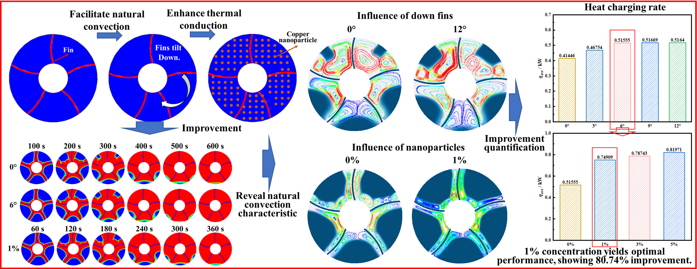
Enhancing the efficiency of phase-change heat storage is vital for maximizing the utilization of renewable energy. This study examines the synergistic effect of non-uniformly shaped fins and nanoparticles on the melting performance of phase-change storage tanks. The problem is addressed using a finite volume framework coupled with the enthalpy–porosity method, with the numerical model rigorously validated against experimental data. The analysis explores the influence of varying fin deflection angles and nanoparticle concentrations on melting dynamics. It is shown that a downward fin deflection of 6° reduces melting time to 570 s, representing a 20.8% improvement over uniform fins. Introducing 1% nanoparticles further accelerates melting, reducing time by 36.54% compared to the nanoparticle-free case. The combined strategy of 6° fin deflection and 1% nanoparticle addition shows the most economic heat storage rate, achieving an exceptional 80.74% enhancement relative to a tank with uniform fins.Graphic Abstract
Keywords
The combustion of fossil fuels produces a large amount of greenhouse gases, exacerbating the climate challenges faced by the globe [1,2]. Therefore, reducing fossil fuels and increasing renewable energy have become an inevitable trend for reducing carbon emission [3]. However, renewable energy has limitations due to its intermittency and instability, which restrict energy conversion efficiency and urgently need to be addressed through efficient thermal energy storage (TES) technologies [4,5]. TES is classified as sensible heat storage, latent heat storage, and thermochemical heat storage [6,7]. Among them, latent heat thermal energy storage (LHTES) is one available method because of small temperature difference and large energy storage density [8,9]. However, in such systems, low thermal conductivity of phase change material (PCM) restricts heat transfer [10,11].
To enhance the heat transfer efficiency, various approaches including active methods and passive methods have been proposed to improve its convective and conductive properties [12,13]. For enhancement on phase change heat storage, method enhancing convection heat transfer, thermal conduction and coupling of both are proposed [14]. In addition, enlarging the heat transfer areas through embedding porous media and fins are proposed [15,16]. Adding fins to enhance heat transfer by enlarging exchanging area is one cost-effective method, and is widely used [17,18]. The fin shape has been extensively studied as a key parameter [19,20]. In addition, the distribution characteristic of fins are studied to reveal the influence mechanism [21,22]. Li et al. [23] manufactured annular fins on the twisted elliptical inner tube to enhance the heat transfer by 156.44%. Guo et al. [24] fabricated asymmetric V-shaped fins and studied effect of physical parameter on melting speed and charging performance. Conclusion is that increasing eccentricity, optimizing fin angle and height, and changing the fin shape could all accelerate melting. Liu et al. [25] researched melting performance of T-shaped fins and plate fins in horizontal heat storage unit and found 34.5% reduction of the melting time. Nakhchi and Esfahani [26] designed a new stepped fin and conducted numerical simulations, showing that compared with traditional horizontal fins, the step ratio of 4 is best, increasing charging rate by up to 65.5%. He et al. [27] experimentally compared charging characteristics of three LHTESs with no fins, annular and spiral fins, finding that spiral fins had superior overall thermal performance, improving thermal efficiency by 66.4%. Wang et al. [28] designed a new fin structure combining curved fins and straight fins, and optimized fins using the response surface method to improve 52.16% charging rate. Fahad et al. [29] modified the shape of traditional longitudinal fins and proposed five new fin shapes and found best and worst structure. Arıcı et al. [30] tested the effect of concentration of Al2O3 nanoparticles on melting time, and found 6.7% saving.
In addition, enhancing thermal conductivity is another effective method to improve heat transfer, such as metal foam and nanoparticles [31,32]. Many researchers use nano-enhanced phase change materials (NePCM) to enhance thermal conduction due to its low cost [33,34]. Adding highly conductive nanoparticles such as CuO [35], SiC [36] and Al2O3 [37] to the base phase change materials, researchers have constructed efficient thermal conduction networks inside PCM. Liu and Yang [38] added Nano-α-Al2O3 to eutectic hydrated salt, and found the supercooling is inhibited and the thermal conductivity is enhanced. Altohamy et al. [39] incorporated Al2O3 into phase change material, and found that charging time is reduced by 32% maximumly. Singh et al. [40] examined charging rate under addition of Al2O3, MgO, and SiO2, and found 33.8%, 33.8%, and 41% enhancement on charging rate, respectively. Recently, carbon nanomaterials with high thermal conductivity have also been added to enhance the thermal conductivity of phase change materials [41,42]. He et al. [43] prepared the composite phase change material by incorporating graphene nanoplatelets and found 176.26% enhancement on conductivity. Shaikh et al. [44] combined single wall carbon nanotubes and phase change material, and tested 13% enhancement on latent heat. Naik and Gumtapure [45] studied the dispersion of graphene nanoparticles in a horizontal LHTES using experimental and numerical methods. The study showed that adding just 0.1%, 0.5%, and 1.0% graphene could reduce the melting time by 9.9%, 17.7%, and 20.2%, respectively. Sachan and Bhattacharya [36] found that adding 1 wt% nanoparticles (Al2O3, CuO, Cu) to phase change materials could increase thermal conductivity but also increase liquid-phase viscosity, resulting in a slowed phase change; therefore, nanoparticles do not always enhance thermal storage performance. Shang et al. [46] used the lattice Boltzmann method to optimize nanoparticle distribution and enhance heat transfer performance by constructing staggered structures within the PCM to separate and confine nanoparticle-enhanced regions.
In addition, multiple studies have focused on exploring the synergistic enhancement between nanoparticles and enhanced heat transfer structures [47]. Hussain et al. [48] combined nanoparticles with PCMs and integrated various shaped fins for experimental and numerical analysis. The results showed that T-fins synergistically combined with nanoparticle-enhanced PCM accelerates charging process. Li et al. [49] manufactured a biomimetic honeycomb fin structure and formed NEPCMs to enhance melting and solidification processes. Results indicated that adding 1.0% nanoparticles could reduce 15.9% charging process. Sattinova et al. [50] revealed effects of internal fins and BeO nanoparticles on charging process. When six fins were used and 5% BeO nanoparticles were added, the LHTES possesses fastest charging rate.
Both fin structure and nanoparticles can enhance phase change process. Therefore, this study proposes the use of coupled arc-shaped fins and nanoparticles to achieve comprehensive enhancement on thermal process. Among them, fin enhanced heat exchange by enlarging heat exchange area, and internal natural convection heat exchange. And adding nanoparticles enables heat exchange enhancement by enhancing internal conduction. However, excessive addition of nanoparticles leads to weakness on natural convection. Therefore, when using two types of strong heat exchange methods to achieve coupled enhanced heat exchange, it is necessary to explore the coupling mechanism between them to provide guidance principles for practical engineering. Different from previous research about combining fins and nanoparticles, this research designed fins through non-uniform design. And this design could further enhance the heat transfer of the bottom phase change material. The subsequent article conducted research on heat storage characteristics under arc-shaped finned coupled nanoparticles. It separately explored mechanisms of fin deflection angles and different nanoparticle concentrations coupled together on the charging.
The enhanced heat exchange of a shell-and-tube heat storage tank using finned plates was proposed in this study. The horizontally placed LHTES is selected, and the finned plates used are arc-shaped plates, as shown in Fig. 1. This LHTES is composed of two concentric circles, with outer diameter of 30 mm and inner diameter of 10 mm. Phase change materials are filled between two circles. The PCM used is paraffin, with the corresponding properties displayed in Table 1. Five curved arc-shaped finned plates are designed to enhance contact area for PCM. Arc-shaped finned plates used are made of aluminum, with a thickness of 0.5 mm. The length of the fins is precisely designed to connect the inner and outer tubes, and they are connected with a curved arc having a radius of 15 mm. For the reference condition, the five fins of the heat storage tank are evenly distributed, with an interval angle of 72°, as shown in Fig. 1a. Since the arc-shaped fins are curved in one direction, the model does not have symmetry. To further improve the heat storage performance, the four finned plates (except the top one) are deflected downwards by 3°, 6°, 9°, and 12°, as shown in Fig. 1. The design of this enhancement measure aims to enhance the phase change melting in the less fusible area at the bottom, thereby further accelerating the overall melting rate. Additionally, nano-particles were added to PCM to achieve further enhancement of charging performance.
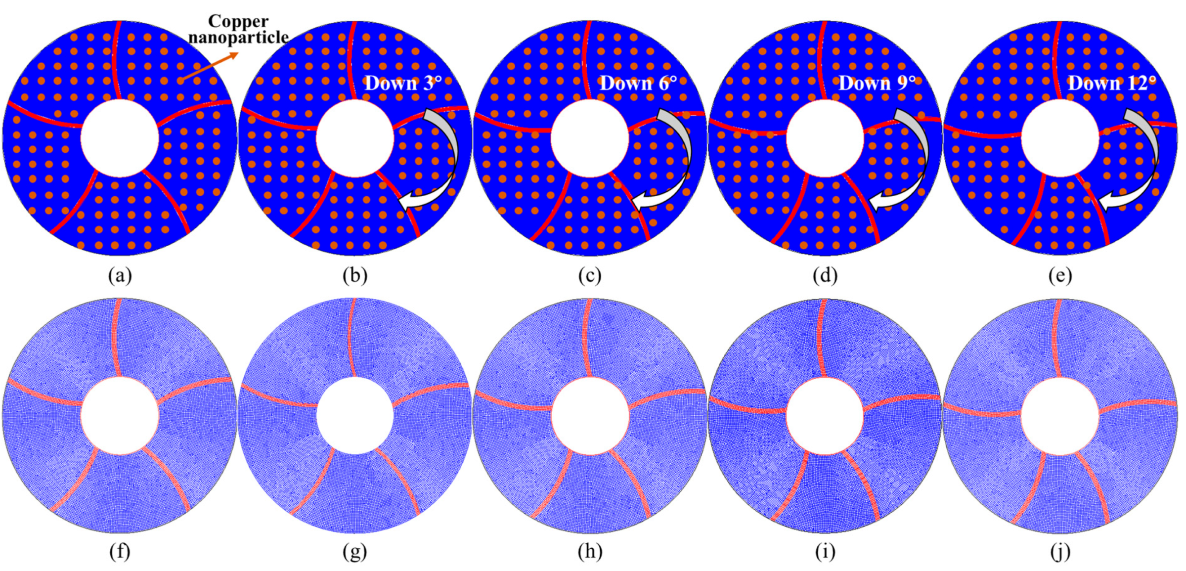
Figure 1: Display of designed models, (a) uniform fins, (b) down 3°, (c) down 6°, (d) down 9°, (e) down 12°, and corresponding numerical model (f) uniform fins, (g) down 3°, (h) down 6°, (i) down 9°, (j) down 12°.
Table 1: Physical properties of material.
| Parameters | Paraffin | Aluminum | Unit |
|---|---|---|---|
| Density | 785 | 2719 | kg·m−3 |
| Special heat capacity | 2850 | 871 | J·kg−1·K−1 |
| Thermal conductivity | 0.2/0.1 | 202 | W·m−1·K−1 |
| Melting temperature | 50–55 | °C | |
| Latent heat | 102.1 | kJ·kg−1 | |
| Kinematic viscosity | 3.65 × 10⁻³ | m2·s1 | |
| Thermal expansion coefficient | 3.09 × 10⁻⁴ | K−1 |
From mathematical control equation of the horizontally placed LHTES, the fluid flow in the model is simplified, and inner boundary is assumed to be constant heating temperature. In this study, since the temperature of the heating medium fluid is 75°C, the boundary of the inner tube is set as Tb = 75°C. Under the heating effect, heat conducts extremely rapidly within the fins, which helps to quickly transfer heat from fluid to each region of PCM. During this transfer process, only heat conduction within the metal occurs, and its control equation is:
When heat is transferred to PCM, the heat causes temperature rise, and further triggers its melting and heat storage. This process involves the flow of PCM and heating of PCM itself. Governing equations for this process are:
Continuity equation:
Momentum equation along x direction:
Momentum equation along y direction:
Energy equation:
Parameter A is damping on velocity of solid PCM, and can be expressed as:
For junction between fin and PCM, the following method is adopted:
This study also utilized nanoparticles to enhance phase change heat transfer. The added nanoparticles were copper nanoparticles, with physical parameters presented in Table 2. When nanoparticles were added to PCM, the density of PCM would change:
The viscosity also varies at different addition ratios:
Adding nanoparticles improves thermal conductivity of PCM, and the thermal conductivity changed to:
Thermal diffusion effect is also considered as:
The empirical coefficient Ckd was determined by the literature [51]. And total effective thermal conductivity is determined as
Table 2: Physical properties of copper nanoparticles.
| Parameters | Copper Nanoparticles | Unit |
|---|---|---|
| Density | 8954 | kg·m−3 |
| Special heat capacity | 383 | J·kg−1·K−1 |
| Thermal conductivity | 400 | W·m−1·K−1 |
| Thermal expansion coefficient | 1.67 × 10⁻⁵ | K−1 |
3 Numerical Setting and Verification
Before solving the above control equations, the research made the following assumptions and then solved the equations accordingly. In the study, selected fluid is assumed to be incompressible Newtonian fluid, with a constant density. The buoyancy force generated by the heating of a fluid is derived from the Boussinesq assumption. Physical properties of the fluid are also assumed to be constant, meaning they do not change with temperature. For the calculation of the entire computational domain, a pressure-based solver is employed. For pressure solution in equation, PRESTO! is employed. The least squares cells method is adopted for solving the spatial variables. For the time term, a second-order upwind difference scheme is employed for solution. During each step of the transient calculation process, when the calculated residual is less than 10−6, it is considered that the calculation has converged.
The number of grids and time step are key influencing parameters for calculations accuracy. It is extremely necessary to conduct an independent verification of grid number and time step before carrying out numerical calculations. In the grid independence verification, we separately plotted the models of 11,322, 30,793, and 63,314 grids, and compared the transient melting fractions. The result is shown in Fig. 2a. The grid number 30,793 yields excellent calculation results and does not require excessive consumption of computing resources. In the verification of time step, we established models of 0.05 s, 0.2 s and 1.0 s. The calculation results are shown in Fig. 2b. A time step of 0.2 s provides relatively accurate calculation accuracy and does not require excessive computational resources. The complete melting time is quantitatively compared in Table 3. Results show that the deviations between selected gird, time step and more accurate one are 4.64% and 2.65%, which convinced the accuracy of established model.
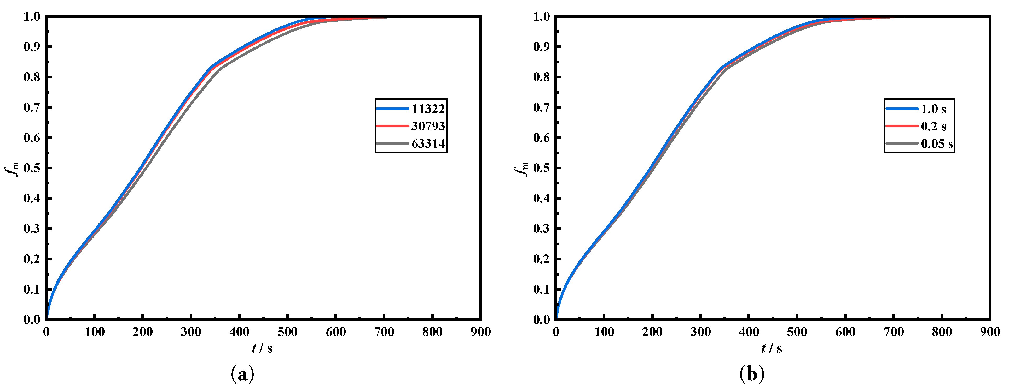
Figure 2: Comparison of melting fraction under different meshes (a) and different time steps (b).
Table 3: Difference about the melting time under different grid sizes and time steps.
| Cases | Melting Time | Deviation | |
|---|---|---|---|
| Grids independence verification | 11,322 | 595 | 21.19% |
| 30,793 | 720 | 4.64% | |
| 63,314 | 755 | ||
| Time steps independence verification | 1.0 s | 640 | 13.25% |
| 0.2 s | 720 | 2.65% | |
| 0.05 s | 740 |
Comparison of the numerical results with the experimental results from the literature verifies the computational accuracy. The established model was a three-tank heat storage system embedded with RT82 wax. Before the simulation began, the heat storage tank was initialized at 27°C. During the simulation, the heating effect of water was simplified to the heating of the wall surface. Since the water temperature was 50°C, the wall temperature of the heating surface was set at 90°C. The temperature change curves at the selected points were extracted from simulation and compared, which are presented in Fig. 3. From the figure, the temperature change trend calculated by the established numerical model is the same as the experiment, and there is a small difference between the two. This also proves that the established numerical model has high accuracy and can be used for subsequent calculation comparisons. And the average deviation between experimental and numerical results is 3.34%.
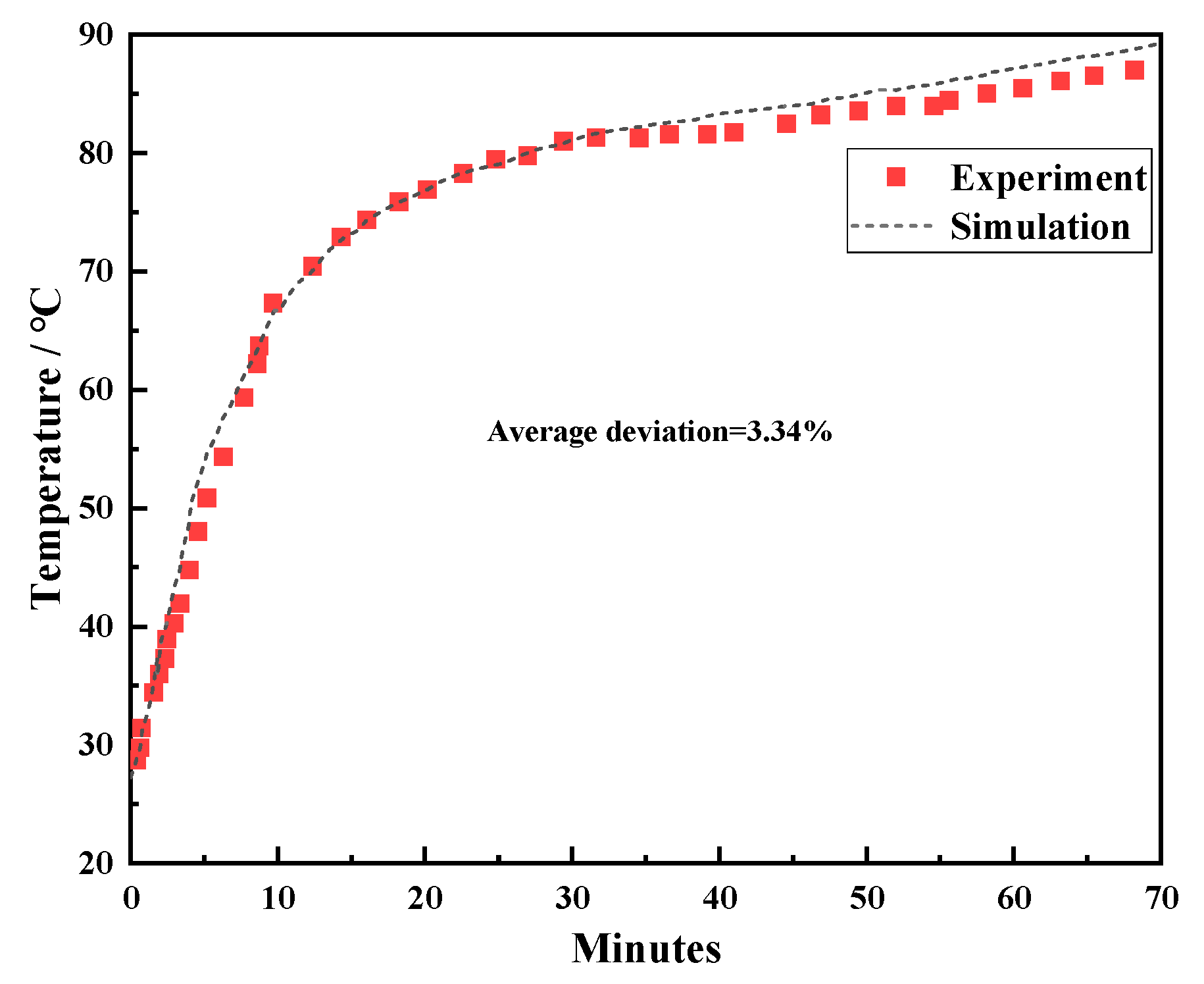
Figure 3: Comparison of simulation results and experimental results [52].
Regarding the verification of the nanoparticle model, we selected a piece of literature to compare with its calculated results. The transient melting rates were calculated separately for the cases where the concentration of nanoparticles was 0% and 10%, and the results are presented in Fig. 4. From the results, the established model has a high degree of computational accuracy and can well simulate the phase change heat transfer process of nanoparticle-enhanced phase change heat storage.
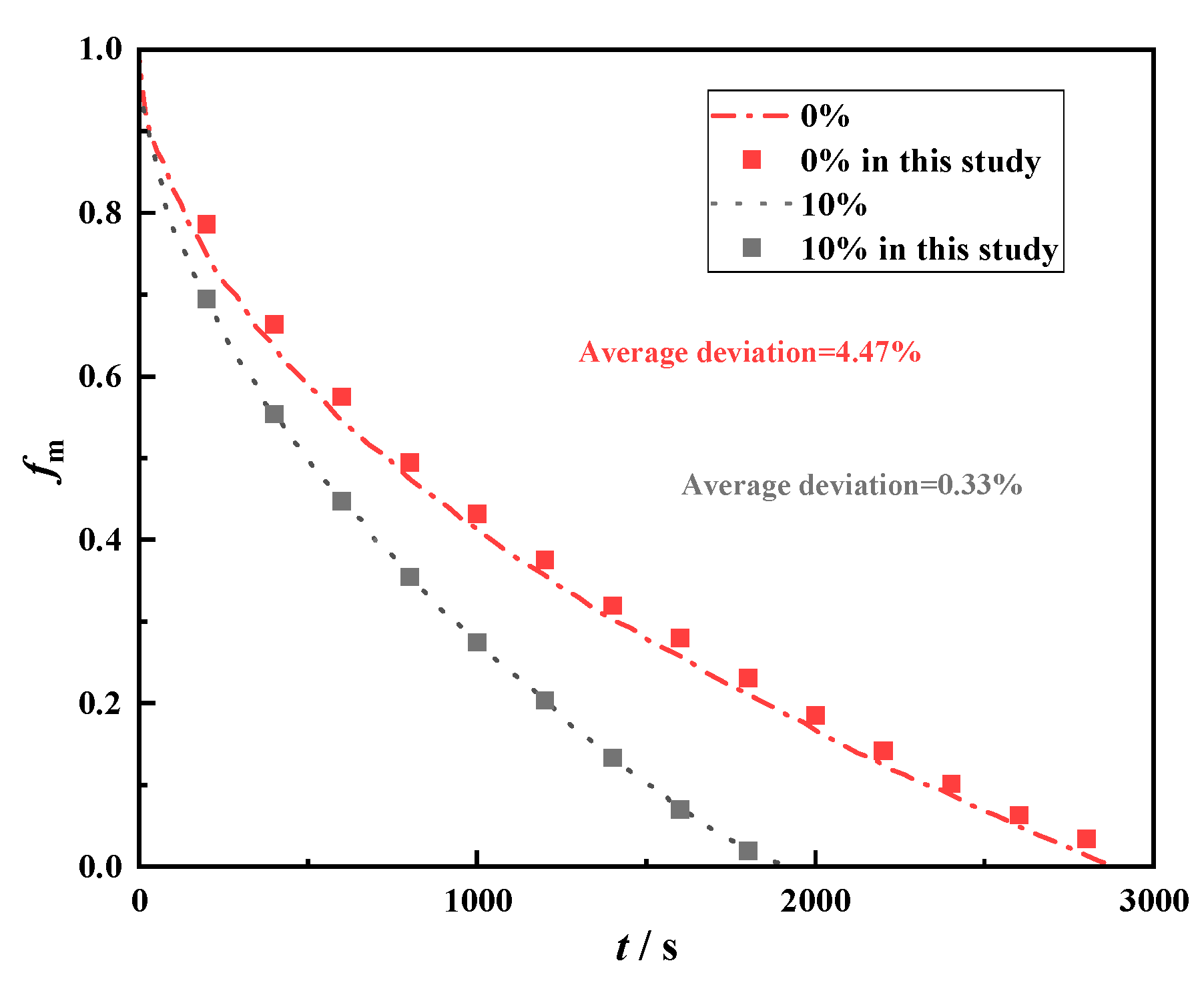
Figure 4: Comparison of simulation results and experimental results [53].
4.1 Analysis of Gradient Metal Foam
4.1.1 Transient Melting Fraction and Complete Melting Time
Fig. 5a,b compares transient melting fraction and complete melting time when deflection angles are 0°, 3°, 6°, 9°, and 12°, respectively. In Fig. 5a, before 50 s, the transient melting fractions of different heat storage tanks are almost exactly the same, with no significant differences. Moreover, the transient melting fractions have a relatively high growth rate at this time. This is because at this point, melting mainly relies on conduction for heat transfer, and melting mainly occurs near heat transfer tube and fin surface. Since area in contact with the PCM inside each tank is equal, transient melting fractions of heat storage tanks do not show significant differences during this stage. While the close contact distance and the large temperature difference for heat transfer are also reasons for the rapid increase in the transient melting fractions. Between 50 s and 300 s, the influence of the five fin deflection angles of different deflection angles on transient mass fractions is small, because the downward deflection design of the four fins is mainly to improve the phase change melting in the difficult-to-melt areas. Before the melting enters the final melting stage, the difference among five storage tanks with different deflection angles is very small, so the melting fractions do not show significant differences at this time. When the melting reaches 300 s, the transient melting fractions show a large difference. And the phase change heat storage with downward deflection angles of 6° and 9° shows faster melting rate. Because the downwardly inclined fins directly transfer heat to the underlying phase change material that is more difficult to melt, compensating for the insufficient heat transfer at the lower part caused by the natural convection that drives the high-temperature phase change material to move upwards, thereby accelerating the melting rate in the later stage. Before 500 s, the highest transient melting fraction occurs under 9° deflection, while after 500 s, the highest transient melting fraction occurs under 6° deflection.
Fig. 5b compares complete melting time of five heat storage tanks, which helps to quantitatively compare enhancement of the five deflection angles. From results, the tank with uniform fins has the slowest melting rate, and complete melting requires 720 s. When the four fins adopt 6° deflection, complete melting is least, 570 s, which is 150 s less than the uniform fin design, with a saving ratio of 20.83%. While adopting the 9° deflection design and 12° deflection design can also significantly reduce melting time, saving 145 s, with saving ratio of 20.14%. Adopting the 3° deflection design saves the complete melting time by 80 s. Comparing the overall trend of change can also show that deflection a certain angle of the four fins helps to significantly enhance melting process, while excessive deflection of the fins will lead to a weakened heat storage enhancing effect. The changing ratio of the complete melting time with respect to the deflection angles of the fins shows that there is a very significant optimization effect during the process of the deflection angles of the fins increasing from 0° to 6°. During the process of increasing the deflection angles of the fins from 6° to 9°, the complete melting time increased. When the deflection angles of the fins increased from 9° to 12°, the complete melting time did not decrease. The complete melting time was detected in in units of 5 s. However, the changing ratio was too small at this point, so the changing ratio could not be determined. However, the reduced sensitivity at angles of deflection greater than 6° also indicates that further increasing the deflection angle does not lead to any further optimization effect.
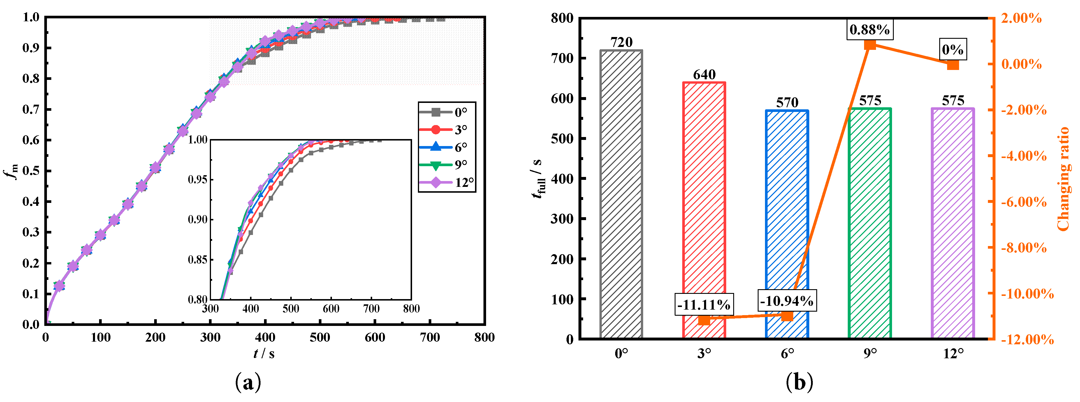
Figure 5: Comparison of the melting fraction and complete melting time for different deflection angles.
Fig. 6 shows a comparison of the transient melting front surfaces when the deflection angles of the four fins are 0°, 3°, 6°, 9°, and 12°. At 100 s, the melting mainly occurs in the phase change material near tube and fins. At this time, proportion of liquid phase change material in the heat storage tank is still relatively small, and heat transfer still relies on conduction. When the melting progresses to 200 s, the proportion of liquid PCM increases, and the internal natural convection gradually intensifies. The melting front surface also undergoes significant changes under natural convection. At 200 s, the upper part of the PCM shows concave and convex areas, which are formed under natural convection. For the upper part of the PCM in heat storage tank, its heating surface is the lower fins and tube. The liquid PCM undergoes natural convection upward heating and floating, and the upward floating fluid continuously washes the un-melted solid PCM in the upper part, thereby forming a concave and convex melting front surface. At 300 s, there are significant differences in the melting front surfaces under different deflection angles. Heat storage tank with a 0° deflection angle has the smallest solid area. The solid unmelted area in tank increases gradually as deflection angle increases. Because as fins gradually deflect downward, the distance between the upper part of PCM and heating surface becomes larger, thereby increasing heat transfer resistance. When melting progresses to 400 s, melting mainly occurs in the lower PCM. The upper PCM has melted under the action of natural convection. The upper part of the heat storage tank with a 12° deflection angle still has a small area of unmelted material, but it also reaches complete melting at 500 s. At 500 s, the area of unmelted lower PCM in heat storage tank with deflection angle of 12° is smaller. While tank with a deflection angle of 0° still has a lot of unmelted phase change material. This is why deflecting the fins downward helps accelerate the melting process in tank. Comparing the melting front at 500 s shows that phase change heat storage with deflection angle of 6° has the least amount of phase-change material in the lower region. But the phase change heat storage with deflection angle of 12° has more phase change material in lower part. And this phenomenon explains why a continued downward tilt of the fin angle would lead to a decrease in the melting rate.
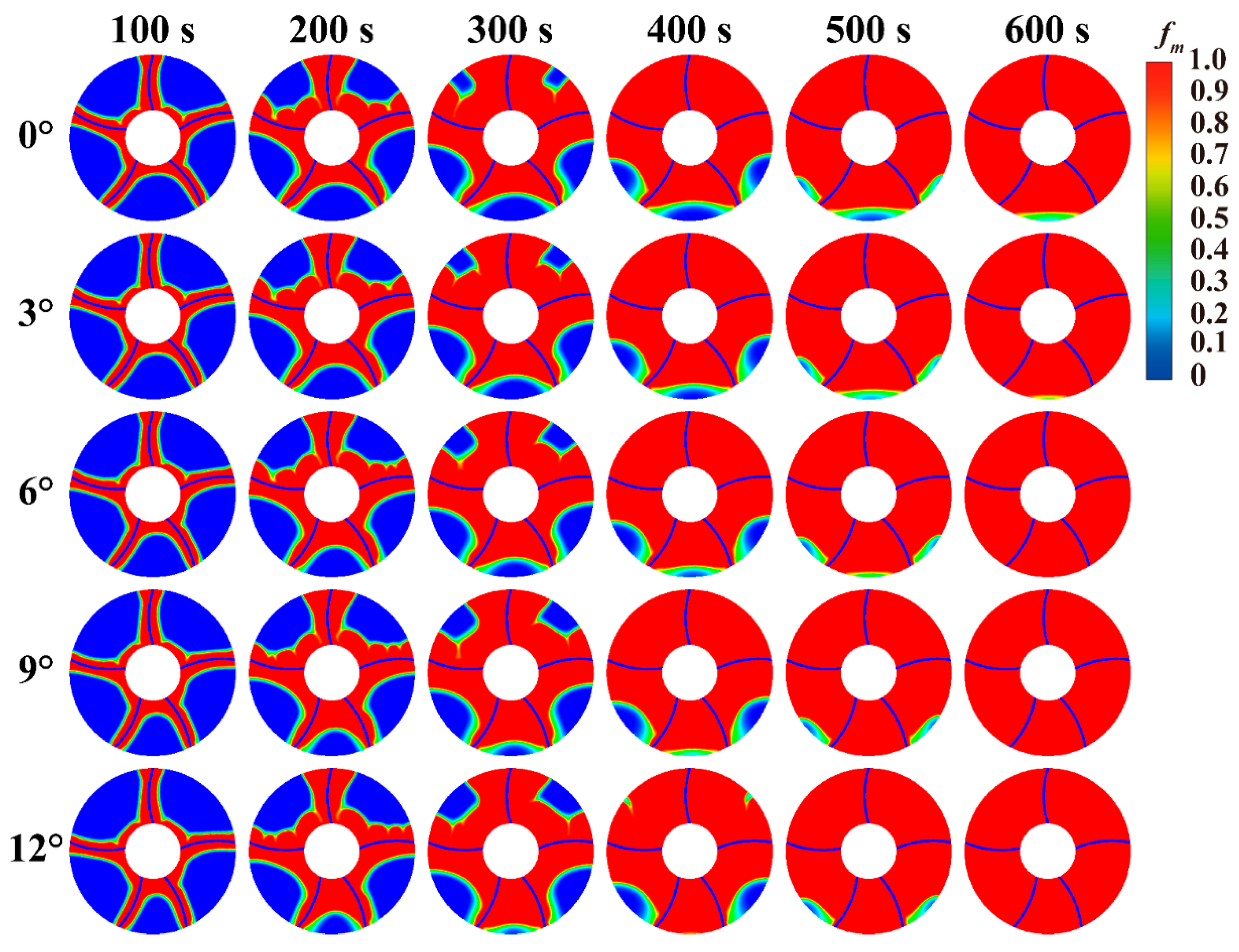
Figure 6: Comparison of melting front in LHTES with different deflection angles.
Fig. 7 compares the melting phase interface and streamline distribution at 300 s when the fins are inclined at 0° and 12°. From the comparison in the figure, at 300 s, there is a significant difference in the phase change materials on the upper part of the phase change heat storage tank. For the condition with a fin inclination angle of 0°, the upper part of the phase change materials has less material to be melted; while for the condition with an inclination angle of 12°, the upper part of the phase change materials has more material to be melted. This is because the downward inclination of the fins leads to an increase in the resistance of heat transfer to the upper phase change materials. The different melting phase interfaces of the two heat storage tanks also result in different natural convection curves inside. In the melting area on the upper right corner of the 12° inclination condition, the natural convection vortices of the phase change materials are more than those with an inclination angle of 0°. In addition, for the heat storage tank with an inclination angle of 12°, the natural convection of the phase change materials in the left and right lower corners is also different. The natural convection is stronger and the flow velocity is smaller in this area within the heat storage tank with an inclination angle of 12°. Therefore, excessive inclination of the fins’ angle leads to slower melting in these two areas.
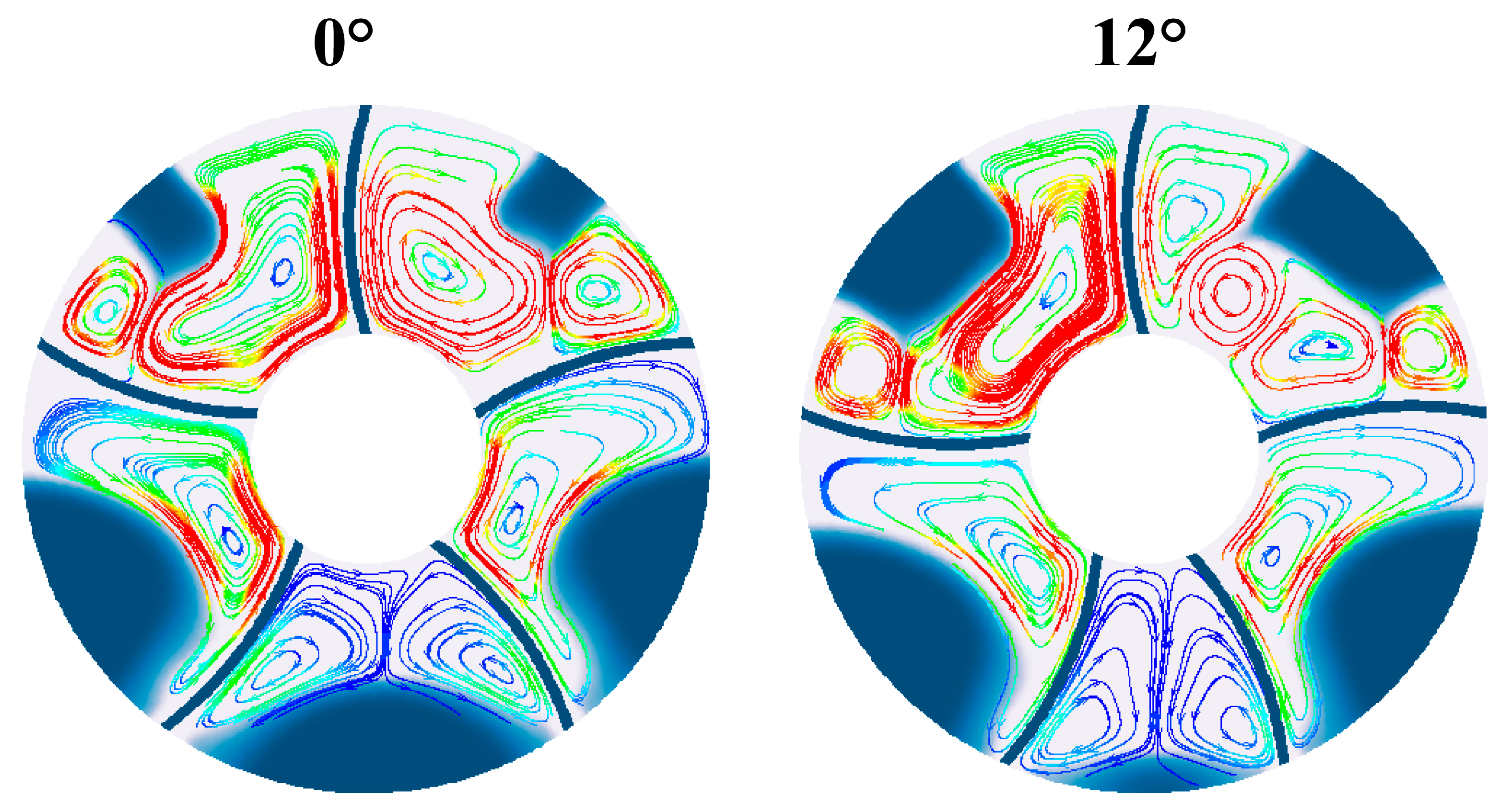
Figure 7: Comparison of streamlines in LHTES with different deflection angles.
4.1.3 Temperature Distribution
Temperature distribution within LHTES can reveal heat transfer mechanism within tank. Therefore, Fig. 8 compares the transient temperature distribution maps during melting process. From figure, there are more low-temperature areas within the tank at 100 s of the melting process, most of which are below 309.6 K. At this time, the high-temperature areas are only in the regions near tube and fins within the tank. Comparison of low-temperature areas in the upper part shows that increasing deflection angle makes the low-temperature area in upper part becomes larger. When melting process reaches 200 s, PCM in tank that were in low-temperature area at 100 s have all increased in temperature, which also lays the foundation for further complete melting. At this time, there are unevenly high temperature areas between un-melted PCM and fins surface. This is the result of the natural convection under the heating effect of fins. At 300 s, low-temperature area gradually increases as the downward deflection angle of the fins increases. As downward deflection prolongs distance for heat transfer to PCM. When the melting process reaches 400 s, almost all upper PCM have completely melted, but there are still lower-temperature areas in the upper part. Under influence of natural convective heat transfer, it becomes a high-temperature area at 600 s. When comparing temperature distributions in five tanks at 600 s, there are some low-temperature unmelted areas in the lower part with a deflection angle of 0°. For a deflection angle of 9° or more, the upper part has already become a high-temperature area.
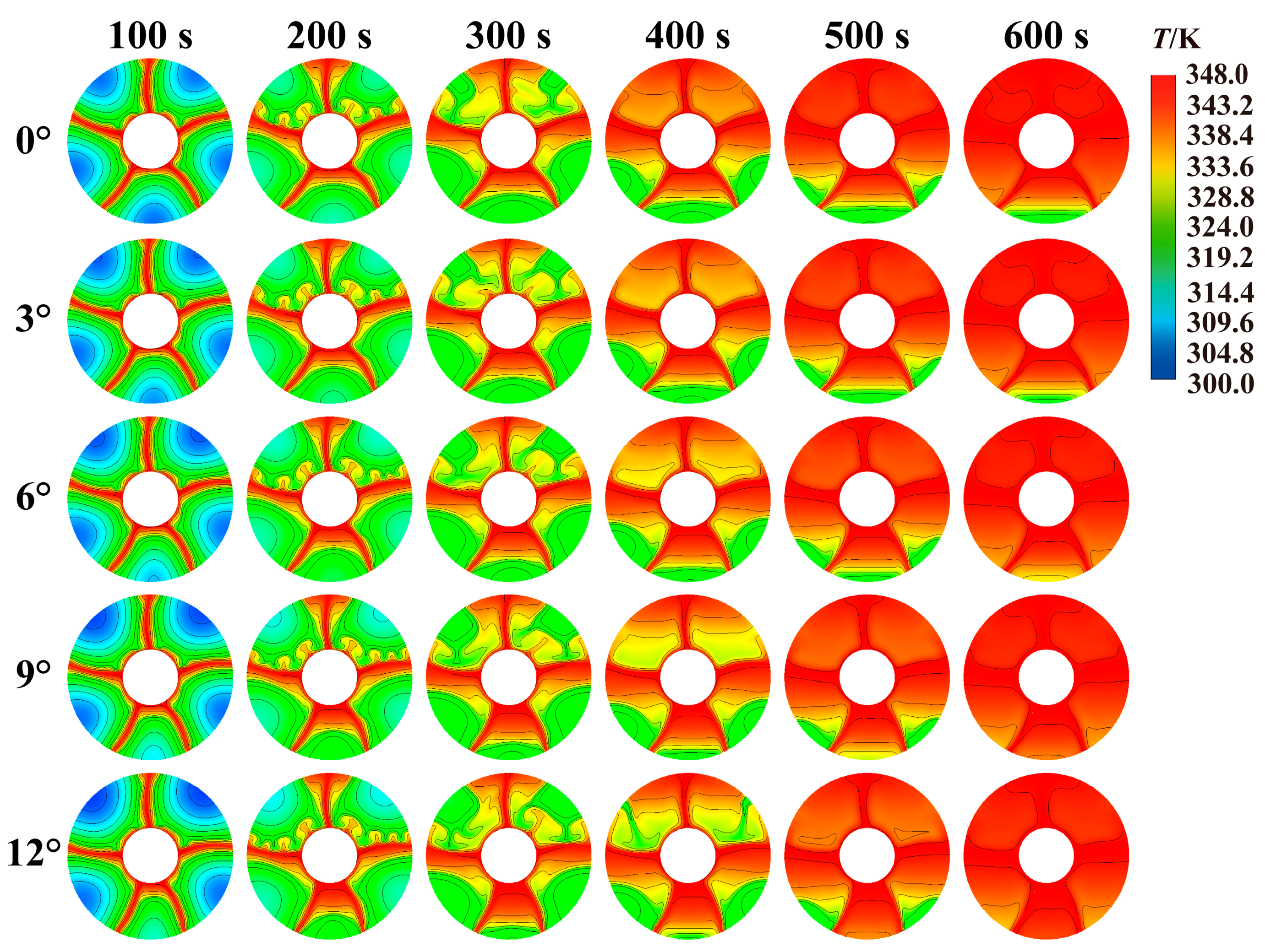
Figure 8: Comparison of temperature distribution inside storage tank with different deflection angles.
4.2 The Influence of Nanoparticle
4.2.1 Transient Melting Fraction and Complete Melting Time
Fig. 9 compares the effects of adding 0%, 1%, 3%, and 5% concentrations of nano-copper particles on the transient phase change melting fraction under five different fin deflection structures. Fig. 9a–e shows the melting fractions of the four heat storage tanks with fin deflection angles of 0°, 3°, 6°, 9°, and 12°, respectively. From the results in the figure, adding copper nanoparticles to the heat storage tanks can significantly enhance the internal charging process. Transient melting fractions in tanks with fin deflection angles of 0°, 3°, 6°, 9°, and 12° under the presence of nanoparticles are significantly higher than those without nanoparticle addition. This also proves that adding nanoparticles to tanks can enhance charging of LHTES by enhancing conduction. Moreover, by comparing the addition of 1%, 3%, and 5% concentrations of nanoparticles to the heat storage tanks, it can be found that increasing concentration of nanoparticles improves melting characteristics. When the nanoparticle concentration is increased to 3% and 5%, the improvement on transient melting fractions in the heat storage tanks is slight. This is because adding 1% of nanoparticles is sufficient to significantly improve conduction of PCM, while excessive addition of nanoparticles will increase viscosity, thereby reducing natural convection within tank and hindering internal phase change heat transfer. Therefore, adding 1% concentration of nanoparticles to the five heat storage tanks is the most economical for melting within the tanks. Excessive addition does not bring significant heat transfer enhancement but also leads to a deterioration in its economic performance.
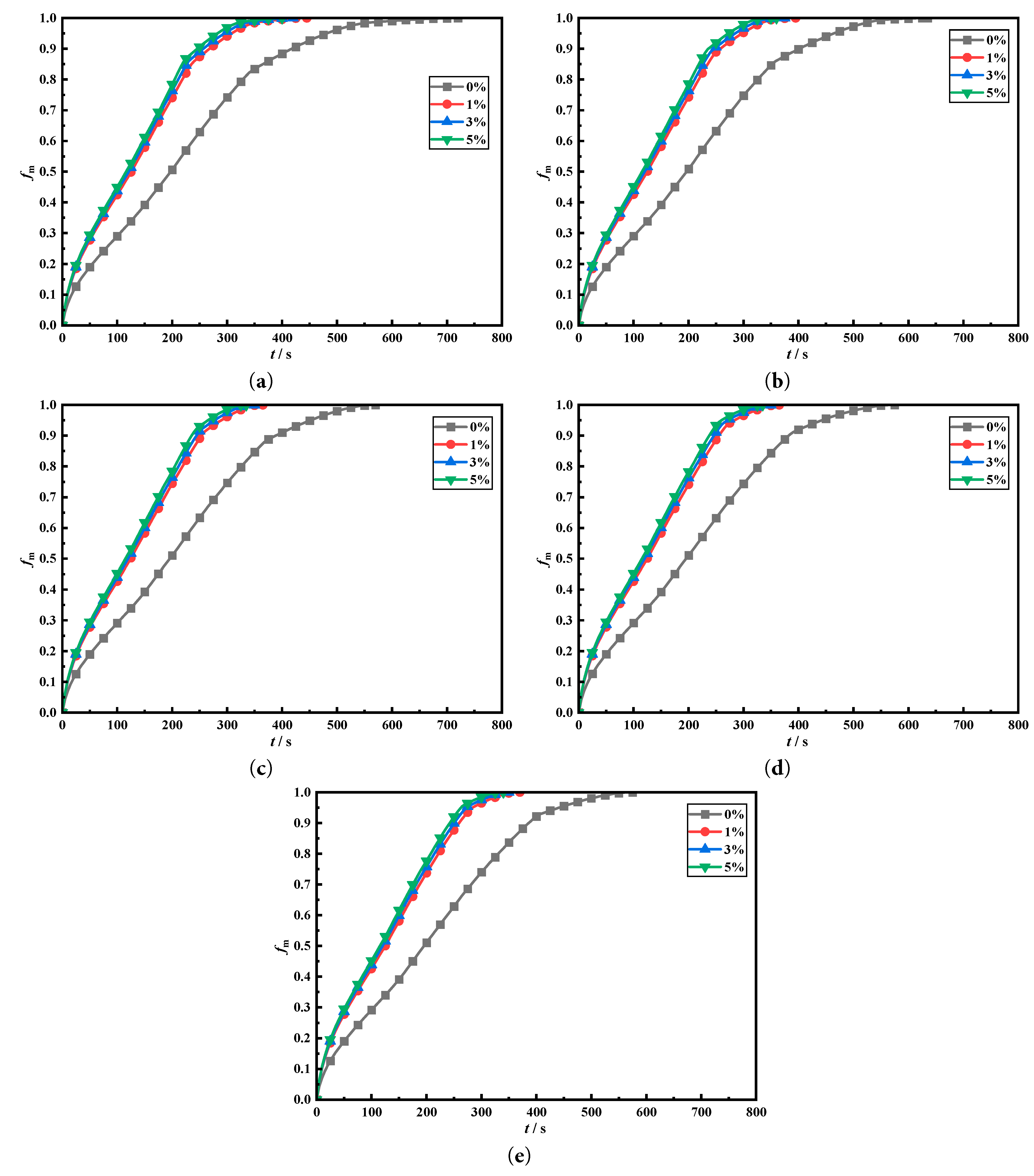
Figure 9: Comparison of enhancement of nanoparticle on transient melting fraction in heat storage tank with different deflection angles.
Fig. 10 quantitatively compares the influence of adding nanoparticles at concentrations of 0%, 1%, 3%, and 5% on the phase change melting of the fins when they are at different deflection angles. Fig. 10a shows the effect of four different nanoparticle addition concentrations on complete melting time when the fins are uniformly distributed. When nanoparticle addition concentration is 1%, the complete melting time is 445 s. Compared to the 720 s of the baseline without nanoparticle addition, 275 s are saved, representing an 38.19% reduction in the storage time. When the nanoparticle addition concentration is 3% and 5%, complete melting times are 420 s and 400 s, respectively. When fins deflected downward by 3°, the complete melting time without nanoparticle addition inside the tank is 640 s. However, adding 1% of nanoparticle saves 245 s for the heat storage tank, representing a 38.28% saving. When the fins are deflected downward by 6°, the complete melting time of heat storage tank decreases to 570 s, which is the lowest storage time for all fin deflection cases and 150 s lower than the storage time of the uniform fin tubes without nanoparticle addition. When the nanoparticle addition concentration is 1%, melting time is 360 s. This is the shortest melting time for all operating conditions and 360 s shorter than without nanoparticle addition for uniform fin tubes, representing a 50.00% saving. Since melting time is monitored every five seconds, the melting times that differ by no more than 5 s are all recorded as the same melting moment. When the deflection angles are 9° and 12°, adding 1% of nanoparticles can save melting time of heat storage tank by 36.52% and 36.65% compared to those without nanoparticle addition. The changing ratio of the complete melting time with the variation in the nanoparticle concentrations are also shown in Fig. 9. By comparing the concentration of nanoparticles in five heat storage tanks and analyzing the impact on the complete melting time, it can be observed that when the nanoparticle concentrations increases from 0% to 1%, there is a very significant enhancing effect. However, during the process of increasing the concentration of nanoparticles from 1% to 5%, a slight enhancement was observed. This indicates that a 1% concentration of nanoparticles is the most economic filling choice. Moreover, the slight change in concentration from 1% to 5% also proves that the selected concentration of nanoparticles in the study contains the optimal solution.
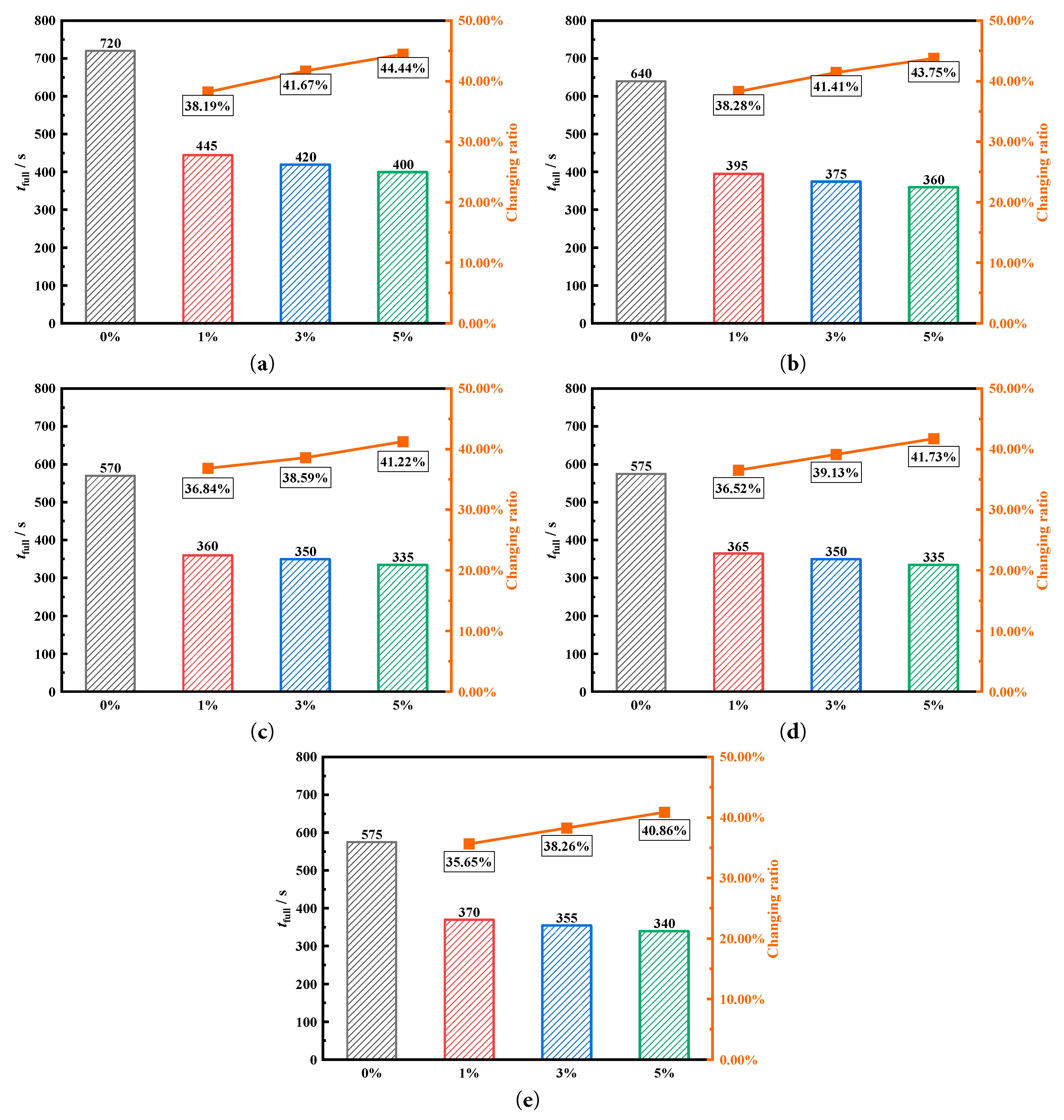
Figure 10: Comparison of the complete melting time under different nanoparticle addition with fin deflection angles of (a) 0°, (b) 3°, (c) 6°, (d) 9° and (e) 12°.
Fig. 11 compares melting front surfaces at different nanoparticle addition concentrations. This also helps to understand the influence of different nanoparticle concentrations on melting. Due to significantly faster melting process after adding nanoparticles compared to one without nanoparticles, Fig. 10 selects heat storage tanks with similar melting ratios for comparison. This also helps to understand the melting front surfaces under different nanoparticle addition concentrations. In early melting stage, melting front surface of heat storage tank with added nanoparticles already shows a significant difference from that without nanoparticles. For melting front surface without nanoparticles added, un-melted PCM on upper part presents a concave-convex melting front shape. For the heat storage tanks with 1% or 5% nanoparticle addition, the upper melting front surface is more smoot. This is because nanoparticles enhance conduction of liquid PCM, thereby weakening its internal natural convection, and thus eliminating the concave-convex surface that is washed away by natural convection. At 300 s, the melting process of the upper and lower parts in tank with nanoparticle addition is relatively similar, while the upper and lower parts melting in tank without nanoparticle addition do not differ much. This is because heat conduction becomes dominant heat transfer in tank with nanoparticle addition, and melting processes are similar. While natural convection in tank without nanoparticle addition is stronger, causing upper PCM melt faster than the lower part. Comparing transient melting front surfaces of 1% and 5% nanoparticle concentrations shows that the melting process with 5% nanoparticle addition is slower than tank with 1% nanoparticle concentration. And the unmelted PCM in upper region is more than in phase change heat storage with 5% nanoparticle concentration. This is because, although the increase in nanoparticle concentration enhances the thermal conductivity, it also increases the viscosity of the phase change material, thereby weakening the natural convection of the phase change material.
Fig. 12 compares the distribution of the melting front surface and flow lines in tank without adding nanoparticles and in tank with 1% nanoparticle addition. From the figure, the natural convection vortices are more widespread in tank without nanoparticle addition, while when nanoparticle addition concentration is 1%, natural convection in tank is weaker, and vortices are mostly large and extensive distributions, no longer in the form of multiple small vortices. Therefore, after adding nanoparticles, the phase change melting front becomes smooth, while in phase change heat storage tank without nanoparticle addition, the melting front surface is unevenly distributed.
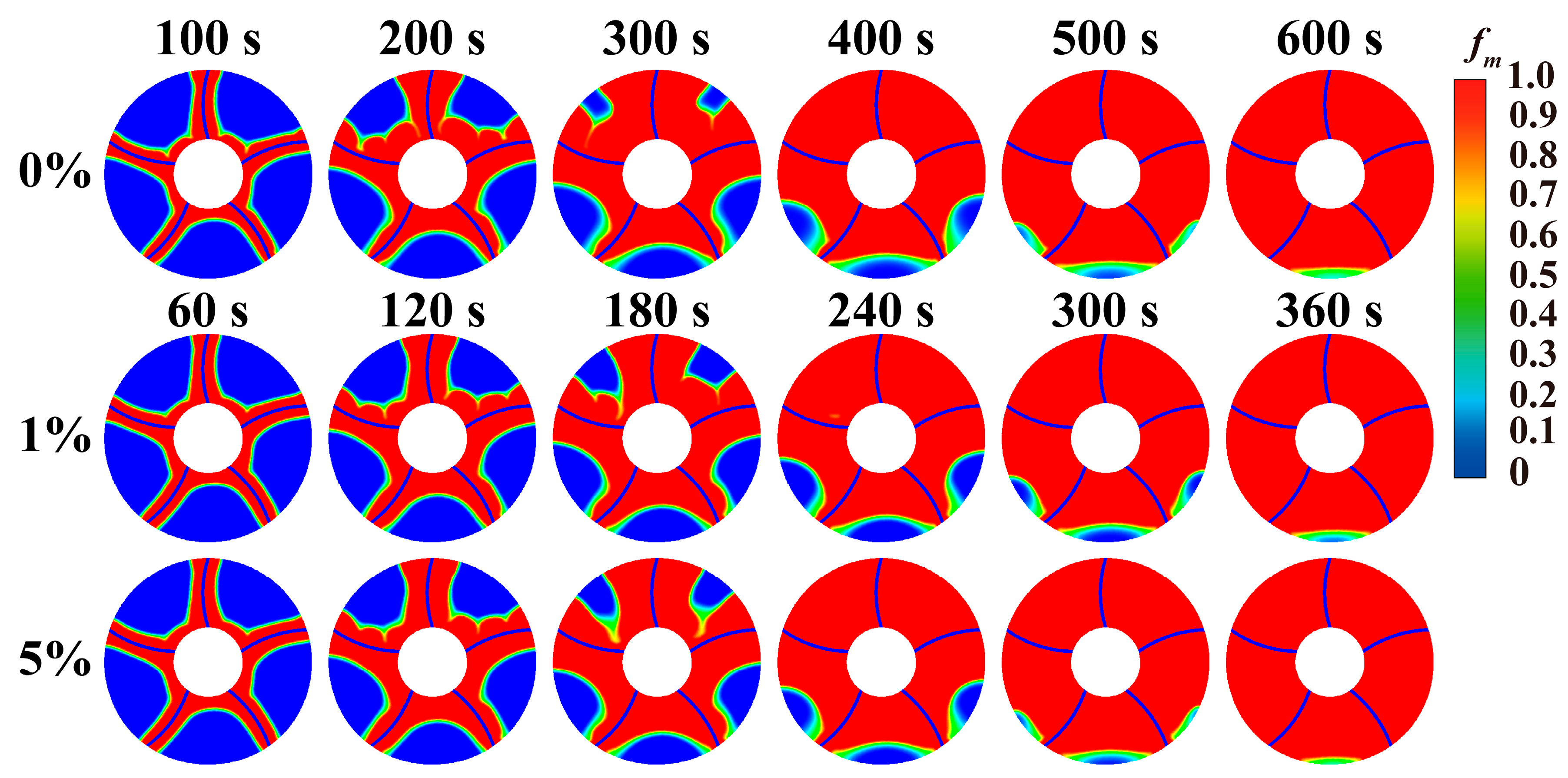
Figure 11: Comparison of melting front at different nanoparticle concentrations.
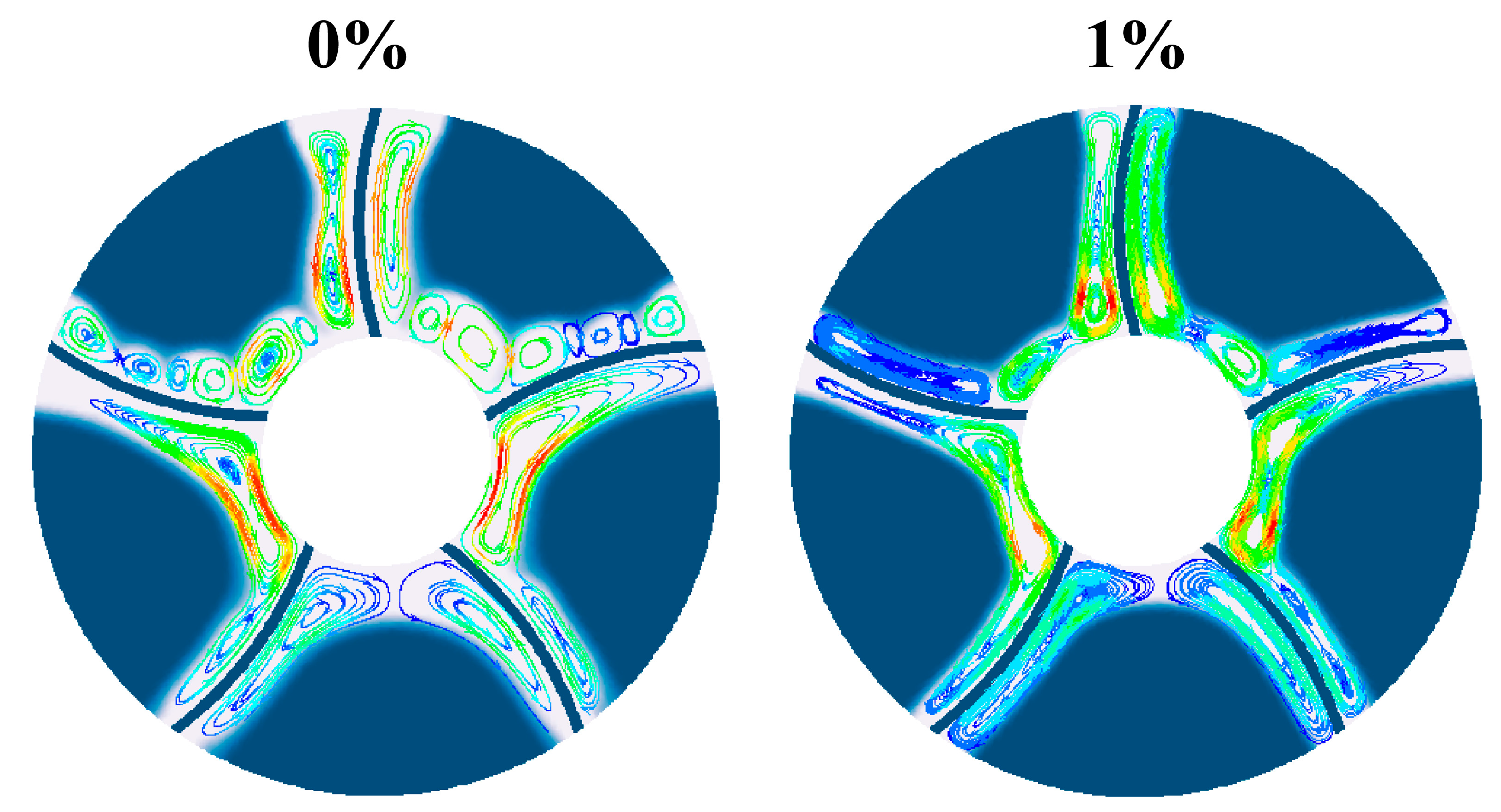
Figure 12: Comparison of streamlines at different nanoparticle concentrations.
4.2.3 Temperature Distribution
Fig. 13 compares the transient temperature distribution cloud diagrams of tank when concentrations of added nanoparticles are 0%, 1% and 5%. This figure continues to compare at the same melting rate moment as mentioned earlier. Therefore, comparing the temperatures is not reasonable. The influence of adding nanoparticles on the temperature distribution mainly manifests in the difference in temperature distribution between the upper and lower parts of the heat storage tank. As the melting process continues, there are large areas of high-temperature regions in the upper part of the storage tank that is not filled with nanoparticles. However, when the concentration of nanoparticles is 1% or 5%, there are no high-temperature areas in the upper part of the storage tank. Because adding nanoparticles increases the viscosity of the phase change material, it inhibits the process of the high-temperature liquid phase change material moving upwards. The upper part of the storage tank without nanoparticles is almost completely melted and forms a large area of high-temperature region. Storage tanks with a concentration of 1% and 5% still have large areas of low-temperature regions. As the melting process progresses further, the upper part of the storage tank without nanoparticles is completely melted, and the temperature gradually rises and increases at an increasingly faster rate. For the storage tank filled with nanoparticles, the melting process of the phase change material on the upper part is always slightly slower than that of the non-phase change material storage tank at the same stage, and the temperature rise speed of the upper phase change material is also slower than that of the storage tank without nanoparticles at the same stage.
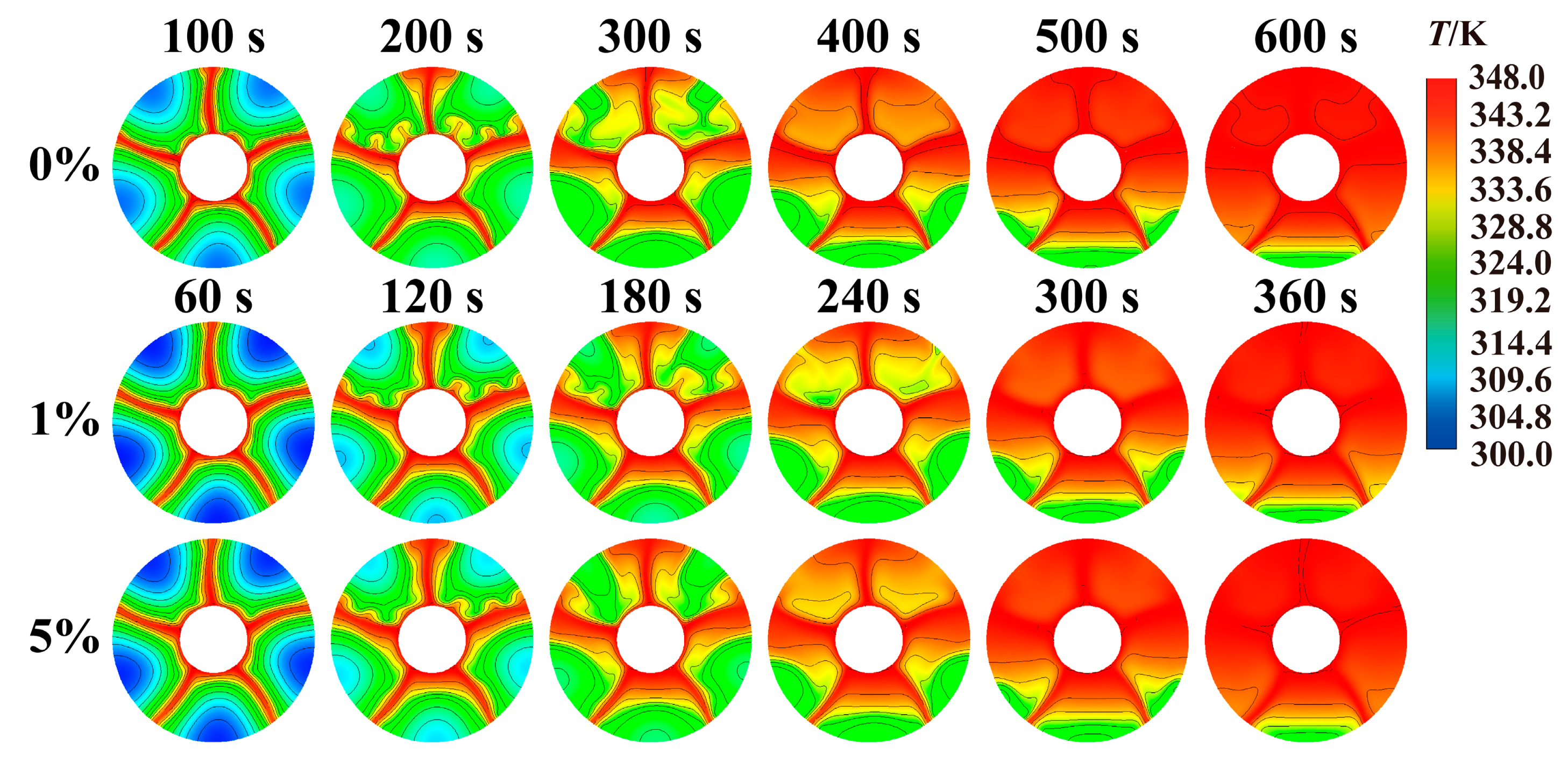
Figure 13: Comparison of temperature distribution at different nanoparticle concentrations.
4.2.4 Transient Heat Storage and Storage Rate
Fig. 14a compares the transient heat storage capacities when the fin deflection angles are 0°, 3°, 6°, 9°, and 12°. From results, transient heat storage capacities of five tanks do not differ much in early melting. However, transient heat storage capacities show significant differences in later melting stage. This is because the adoption of fin deflection design can enhance melting characteristics within tanks, thereby affecting the subsequent heat storage rate. After 350 s, transient heat storage capacities in tanks with fin deflection design are all higher than those without fin deflection design, which also proves the benefits of using fin deflection design in the heat storage tanks. Fig. 14b compares transient heat storage capacities in tanks when nanoparticle addition concentrations are 0%, 1%, 3%, and 5%. Adding nanoparticles to tanks enhances phase change heat storage rate, and transient heat storage capacity within tanks is significantly larger compared to heat storage tanks without nanoparticle addition. Transient heat storage rate in tank increases with increasement of nanoparticle addition concentration of 1%. Tank with a nanoparticle concentration of 1% is the most economic. This is because the higher the concentration of nanoparticles added to the tank, the higher the viscosity of PCM, which is not conducive to natural convection. Therefore, nanoparticle concentration should be appropriate.
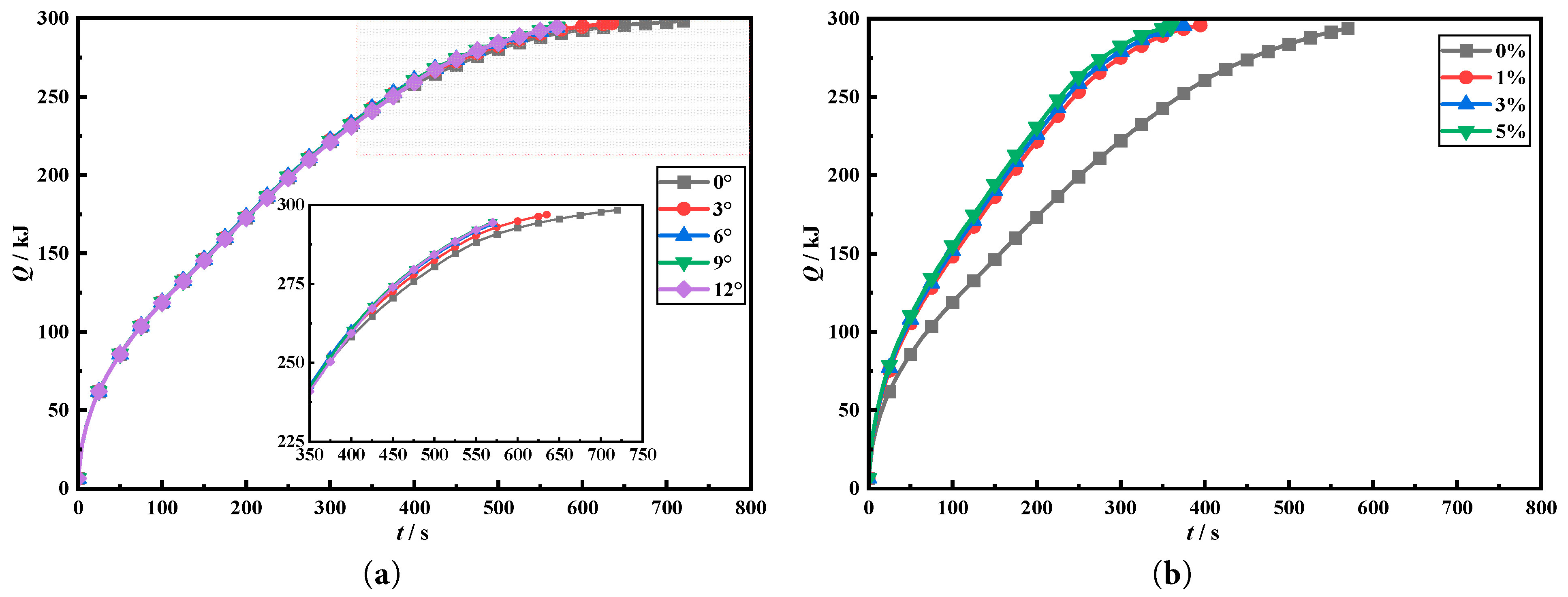
Figure 14: Comparison of the transient heat storage under different nanoparticle addition.
Fig. 15a,b calculated average heat storage rate to quantitatively compare effects of deflection angle and the concentration of the nanoparticles on charging performance. Fig. 15a shows that when deflection angle is 9°, average heat storage rate is the fastest, at 0.51669 kW, which is 0.10223 kW higher than tank without fin deflection, with an increase ratio of 24.67%. The other fin deflection angles also show faster heat storage rates compared to the fin without deflection. Fig. 15b compares the effects of different nanoparticle addition concentrations at a deflection angle of 6° on heat storage rate. Addition of nanoparticles significantly improves the heat storage rate. When the nanoparticle addition concentration is 1%, the average heat storage rate is most economic, at 0.74909 kW, which is 0.23354 kW higher than the baseline condition of 0.51669 kW, with an increase ratio of 45.29%. Among them, the heat storage rate of 0.74909 kW is also the best heat storage rate under the coupling effect of fin deflection and nanoparticle addition, which is 0.33463 kW higher than the baseline condition (no fin deflection and no nanoparticles) of 0.41446 kW, with an increase ratio of 80.74%. This optimization proves optimization of coupling fin deflection and nanoparticle addition on heat storage rate.
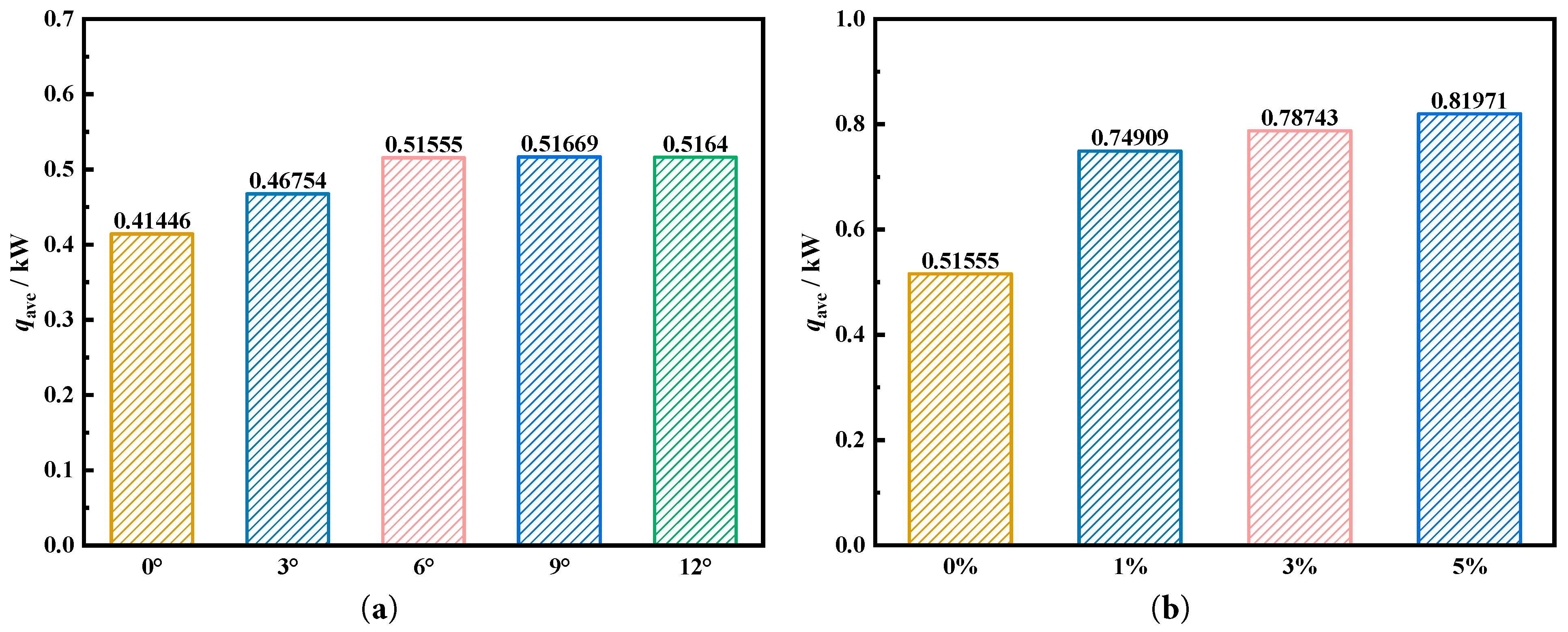
Figure 15: Comparison of the average heat storage rate under different nanoparticle addition.
The enhancement of coupling action of fin deflection angle and nanoparticle filling concentration on the heat storage performance is investigated in this paper. Firstly, influence of different deflection angles on melting characteristics and temperature characteristics of tank was explored. Then, effect of different nanoparticle filling concentrations on the melting phase interface and temperature characteristics is revealed. Finally, impact of the deflection angle and nanoparticle filling concentration was investigated. Following main conclusions were obtained:
- 1.When the four lower fins adopt a 6° deflection design, the time required to achieve complete melting is the shortest, at 570 s, which is 150 s less than the uniform fin design, representing a 20.83% reduction.
- 2.Adding nanoparticles can enhance their heat conduction and improve phase change heat storage. However, excessive addition of nanoparticles will lead to an increase in the viscosity of the phase change material, thereby weakening its natural convection. The optimal addition concentration should be the one that achieves the best coupling effect between enhanced heat conduction and weakened natural convection.
- 3.For the heat storage tanks with 1% or 5% nanoparticles added, the upper front is a smooth one. This is because the addition of nanoparticles increases conduction of liquid PCM, thereby weakening natural convection within it. As a result, there are no uneven surfaces eroded by natural convection.
- 4.When the concentration of nanoparticles added was 1%, melting time is most economic. For finned heat storage with deflection angle being 6°, melting time is saved by 36.54% compared to the deflected case without nanoparticles. The heat storage rate is 0.74909 kW, representing 80.74% increase than uniform finned tube.
The phase change heat storage enhancement technology proposed in this research can be applied to various scenarios such as mobile heat storage devices, peak-valley electricity price heat storage, solar heat collectors, and industrial waste heat recovery. However, when applied to actual heat storage tanks, it will result in different quantitative enhancement effects. This is mainly due to certain errors in numerical simulation and actual application, including the neglect of contact thermal resistance and the failure to consider the change of material properties with temperature. This will result in different optimal deflection angles and nanoparticle filling concentrations. Therefore, for a specific heat storage tank, it is necessary to further carefully investigate its optimal deflection angle and nanoparticle filling concentration to determine the best heat storage effect and to more efficiently utilize thermal energy. However, it is undeniable that the proposed method can indeed effectively enhance the heat storage effect, providing a foundation for the efficient heat storage and utilization of the heat storage tank.
Acknowledgement:
Funding Statement: The authors received no specific funding.
Author Contributions: Conceptualization, Xujun Gao, Wei Chen, Bo Ma, Rukun Hu, Liao Zhang, Yongzhi Lei, Wenbin Han, Yuanji Li and Xiaohu Yang; methodology, Xujun Gao, Wei Chen, Bo Ma and Rukun Hu; software, Liao Zhang, Yongzhi Lei, Wenbin Han and Yuanji Li; validation, Xujun Gao, Wei Chen and Bo Ma; formal analysis, Rukun Hu, Liao Zhang, Yongzhi Lei, Wenbin Han and Yuanji Li; investigation, Wenbin Han and Yuanji Li; resources, Xiaohu Yang; data curation, Xujun Gao; writing—original draft preparation, Xujun Gao; writing—review and editing, Xujun Gao and Xiaohu Yang; visualization, Liao Zhang, Yongzhi Lei and Wenbin Han; supervision, Xiaohu Yang; project administration, Xiaohu Yang; funding acquisition, Xiaohu Yang. All authors reviewed and approved the final version of the manuscript.
Availability of Data and Materials: Data available on request from the authors.
Ethics Approval: Not applicable.
Conflicts of Interest: The authors declare no conflicts of interest.
References
1. Rezaei S , Hormaza Mejia A , Wu Y , Reed J , Brouwer J . Global warming impacts of the transition from fossil fuel conversion and infrastructure to hydrogen. Appl Energy. 2025; 397( C): 126363. doi:10.1016/j.apenergy.2025.126363. [Google Scholar] [CrossRef]
2. Su CW , Pang LD , Qin M , Lobonţ OR , Umar M . The spillover effects among fossil fuel, renewables and carbon markets: Evidence under the dual dilemma of climate change and energy crises. Energy. 2023; 274: 127304. doi:10.1016/j.energy.2023.127304. [Google Scholar] [CrossRef]
3. Liu E , Albaheth HE , Shafiq MA . Strategic directions for renewable energy in China: Analyzing the transition from fossil fuels to dirty free technologies. Energy Strategy Rev. 2025; 59: 101711. doi:10.1016/j.esr.2025.101711. [Google Scholar] [CrossRef]
4. Selänniemi A , Hellström M , Björklund-Sänkiaho M . Long-duration energy storage technology adoption: Insights from U.S. energy industry experts. Energy Rep. 2025; 13: 378– 96. doi:10.1016/j.egyr.2024.12.027. [Google Scholar] [CrossRef]
5. Zhu Y , Shao Y , Ni Y , Li Q , Wang K , Zang P , et al. Comparative techno-economic evaluation of energy storage technology: A multi-time scales scenario-based study in China. J Energy Storage. 2024; 89: 111800. doi:10.1016/j.est.2024.111800. [Google Scholar] [CrossRef]
6. Sarbu I , Sebarchievici C . A comprehensive review of thermal energy storage. Sustainability. 2018; 10( 1): 191. doi:10.3390/su10010191. [Google Scholar] [CrossRef]
7. Xie Y , Liu J , Ma W , Sheng J , Zhang P . Review of the heat transfer enhancement for phase change heat storage devices. J Energy Storage. 2024; 86: 111336. doi:10.1016/j.est.2024.111336. [Google Scholar] [CrossRef]
8. Cárdenas B , León N . High temperature latent heat thermal energy storage: Phase change materials, design considerations and performance enhancement techniques. Renew Sustain Energy Rev. 2013; 27: 724– 37. doi:10.1016/j.rser.2013.07.028. [Google Scholar] [CrossRef]
9. Kabasa MS , Biira S , Kanyarusoke KE . Developments in the design optimization of cascaded PCM latent heat thermal energy storage units: A review. Energy Storage Sav. 2025; 4( 4): 439– 62. doi:10.1016/j.enss.2025.03.002. [Google Scholar] [CrossRef]
10. Afaynou I , Faraji H , Choukairy K , Djebali R . Metal foam reinforced phase change material for passive thermal control of multiple electronic components. Int J Therm Sci. 2026; 220: 110329. doi:10.1016/j.ijthermalsci.2025.110329. [Google Scholar] [CrossRef]
11. Al-mahmodi AF , Munusamy Y , Atta MR . Predictive modeling of thermal conductivity in PCM composites using artificial Intelligence. Sustain Chem Clim Action. 2025; 7: 100145. doi:10.1016/j.scca.2025.100145. [Google Scholar] [CrossRef]
12. Liebenberg L , Meyer JP . In-tube passive heat transfer enhancement in the process industry. Appl Therm Eng. 2007; 27: 2713– 26. doi:10.1016/j.applthermaleng.2007.06.003. [Google Scholar] [CrossRef]
13. Sheikholeslami M , Bhatti MM . Active method for nanofluid heat transfer enhancement by means of EHD. Int J Heat Mass Transf. 2017; 109: 115– 22. doi:10.1016/j.ijheatmasstransfer.2017.01.115. [Google Scholar] [CrossRef]
14. Afaynou I , Faraji H , Choukairy K , Djebali R , Rezk H . Comprehensive analysis and thermo-economic optimization of a hybrid phase change material-based heat sink for electronics cooling. Heat Transf. 2025; 54( 6): 3754– 74. doi:10.1002/htj.23382. [Google Scholar] [CrossRef]
15. Li Y , Huang X , Li Z , Xie Y , Yang X , Li MJ . Structural optimization of latent heat storage tank filled with nickel foam. Appl Therm Eng. 2025; 267: 125780. doi:10.1016/j.applthermaleng.2025.125780. [Google Scholar] [CrossRef]
16. Hariss M , Gounni A , El Alami M . Impact of innovative fin design on phase change material melting for thermal energy storage system. Appl Therm Eng. 2023; 231: 120914. doi:10.1016/j.applthermaleng.2023.120914. [Google Scholar] [CrossRef]
17. Yu G , Sun Y , Zhou Y , Xu H . Review on heat transfer structures for enhancing thermal performance of latent heat thermal energy storage systems. J Energy Storage. 2025; 132: 117908. doi:10.1016/j.est.2025.117908. [Google Scholar] [CrossRef]
18. Zhang K , Li H , Wang L , Song K , Zhang Q , Shi G . Experimental investigation on the thermal performance of longitudinally finned tube latent heat thermal energy storage unit. Appl Therm Eng. 2025; 279: 127690. doi:10.1016/j.applthermaleng.2025.127690. [Google Scholar] [CrossRef]
19. Zhao Z , Hu B , He J , Lin M , Ke H . Effect of fin shapes on flow boiling heat transfer with staggered fin arrays in a heat sink. Appl Therm Eng. 2023; 225: 120179. doi:10.1016/j.applthermaleng.2023.120179. [Google Scholar] [CrossRef]
20. Sagar MD , Puttaraja MR , Gowtham GK , Naveen Kumar R , Varun Kumar RS , Prasannakumara BC , et al. A comprehensive review on geometric variations in fin configurations: Experimental and mathematical studies. Arch Comput Meth Eng. 2025: 1– 50. doi:10.1007/s11831-025-10470-x. [Google Scholar] [CrossRef]
21. He F , Hu C , Gao W , Li S , Meng X . Effect of inclination angles on heat transfer characteristics of solid and perforated spiral finned heat exchangers. Int Commun Heat Mass Transf. 2025; 164: 108920. doi:10.1016/j.icheatmasstransfer.2025.108920. [Google Scholar] [CrossRef]
22. Kothari R , Sahu SK , Kundalwal SI , Sahoo SP . Experimental investigation of the effect of inclination angle on the performance of phase change material based finned heat sink. J Energy Storage. 2021; 37: 102462. doi:10.1016/j.est.2021.102462. [Google Scholar] [CrossRef]
23. Li X , Chen S , Tan Y , Tian G , Wang Z , Tang S , et al. Thermal storage performance of a novel shell-and-tube latent heat storage system: Active role of inner tube improvement and fin distribution optimization. Renew Energy. 2024; 228: 120695. doi:10.1016/j.renene.2024.120695. [Google Scholar] [CrossRef]
24. Guo X , Han X , Bo X , Liu Z , Yang Y , Han Z . Analysis of the influence of asymmetric V-shaped fins on the melting of phase change materials in latent heat storage units. Int J Heat Mass Transf. 2024; 231: 125858. doi:10.1016/j.ijheatmasstransfer.2024.125858. [Google Scholar] [CrossRef]
25. Liu J , Hu P , Liu Z , Nie C . Enhancement effect of T-shaped fins on phase change material melting in a horizontal shell-and-tube storage unit. Int J Heat Mass Transf. 2023; 208: 124044. doi:10.1016/j.ijheatmasstransfer.2023.124044. [Google Scholar] [CrossRef]
26. Nakhchi ME , Esfahani JA . Improving the melting performance of PCM thermal energy storage with novel stepped fins. J Energy Storage. 2020; 30: 101424. doi:10.1016/j.est.2020.101424. [Google Scholar] [CrossRef]
27. He F , Bo R , Hu C , Meng X , Gao W . Employing spiral fins to improve the thermal performance of phase-change materials in shell-tube latent heat storage units. Renew Energy. 2023; 203: 518– 28. doi:10.1016/j.renene.2022.12.091. [Google Scholar] [CrossRef]
28. Wang C , Yao S , Chen X , Yan X , Zhan X . Thermal performance analysis of arc-shaped fins of horizontal latent heat thermal energy storage system. Int J Heat Fluid Flow. 2025; 112: 109748. doi:10.1016/j.ijheatfluidflow.2025.109748. [Google Scholar] [CrossRef]
29. Fahad MK , Ifraj NF , Haque MR , Chowdhury NM , Fatema-Tuj-Zohora . Numerical investigation on consecutive charging and discharging of PCM with Modified longitudinal fins in shell and tube thermal energy storage. Results Eng. 2024; 24: 103577. doi:10.1016/j.rineng.2024.103577. [Google Scholar] [CrossRef]
30. Arıcı M , Tütüncü E , Kan M , Karabay H . Melting of nanoparticle-enhanced paraffin wax in a rectangular enclosure with partially active walls. Int J Heat Mass Transf. 2017; 104: 7– 17. doi:10.1016/j.ijheatmasstransfer.2016.08.017. [Google Scholar] [CrossRef]
31. Li Y , Xie Y , Gao J , Yang X , Sundén B . Solidification characteristics in rotating gradient metal foam based on Taguchi and response surface analysis. Int J Heat Mass Transf. 2025; 250: 127324. doi:10.1016/j.ijheatmasstransfer.2025.127324. [Google Scholar] [CrossRef]
32. Li J , Mo S , Zhou Z , Du Y , Jia L , Chen Y . Nanoparticle-enhanced phase change materials for thermal energy storage: A critical review. Renew Sustain Energy Rev. 2025; 223: 116040. doi:10.1016/j.rser.2025.116040. [Google Scholar] [CrossRef]
33. Adera B , Ancha VR , Tadiwose T , Getahun E . Nano enhanced phase change materials for thermal energy storage system applications: A comprehensive review of recent advancements and future challenges. Int J Thermofluids. 2025; 30: 101418. doi:10.1016/j.ijft.2025.101418. [Google Scholar] [CrossRef]
34. Najatishendi M , Alipour M , Ghaffarian S . Enhancing the thermal energy storage of ionic liquid based phase change material by using silicon carbide nanoparticles. Ceram Int. 2026; 52( 1): 298– 306. doi:10.1016/j.ceramint.2025.11.318. [Google Scholar] [CrossRef]
35. Sachan D , Bhattacharya J . Characterization of paraffin wax-based nano-enhanced phase change materials with Al2O3, CuO and Cu nanoparticles and their performance comparison for heat storage application. Therm Sci Eng Prog. 2025; 66: 104031. doi:10.1016/j.tsep.2025.104031. [Google Scholar] [CrossRef]
36. Karuppusamy S , Sambandam P , Selvaraj M , Kaliyaperumal G , Mariadhas A , Deepak JR . Enhancing heat transfer efficiency in shell-and-tube heat exchangers with SiC and CNT-infused alkaline water nanofluids. Desalin Water Treat. 2024; 317: 100157. doi:10.1016/j.dwt.2024.100157. [Google Scholar] [CrossRef]
37. Qin Y . Numerical modeling of energy storage unit during freezing of paraffin utilizing Al2O3 nanoparticles and Y-shape fin. J Energy Storage. 2021; 44: 103452. doi:10.1016/j.est.2021.103452. [Google Scholar] [CrossRef]
38. Liu Y , Yang Y . Use of nano-α-Al2O3 to improve binary eutectic hydrated salt as phase change material. Sol Energy Mater Sol Cells. 2017; 160: 18– 25. doi:10.1016/j.solmat.2016.09.050. [Google Scholar] [CrossRef]
39. Altohamy AA , Abd Rabbo MF , Sakr RY , Attia AAA . Effect of water based Al2O3 nanoparticle PCM on cool storage performance. Appl Therm Eng. 2015; 84: 331– 8. doi:10.1016/j.applthermaleng.2015.03.066. [Google Scholar] [CrossRef]
40. Singh SK , Verma SK , Kumar R . Thermal performance and behavior analysis of SiO2, Al2O3 and MgO based nano-enhanced phase-changing materials, latent heat thermal energy storage system. J Energy Storage. 2022; 48: 103977. doi:10.1016/j.est.2022.103977. [Google Scholar] [CrossRef]
41. ELSihy ES , Xie H , Lin H , Du X , Wang Z . Combined effects of upward eccentricity and volume fraction of graphene nanoparticles on the melting performance of a horizontal double-tube latent heat storage unit. Int Commun Heat Mass Transf. 2024; 158: 107906. doi:10.1016/j.icheatmasstransfer.2024.107906. [Google Scholar] [CrossRef]
42. Nandi A , Biswas N . Melting dynamics and energy efficiency of nano-enhanced phase change material (NePCM) with graphene, Al2O3, and CuO for superior thermal energy storage (TES). J Energy Storage. 2025; 109: 115076. doi:10.1016/j.est.2024.115076. [Google Scholar] [CrossRef]
43. He M , Yang L , Lin W , Chen J , Mao X , Ma Z . Preparation, thermal characterization and examination of phase change materials (PCMs) enhanced by carbon-based nanoparticles for solar thermal energy storage. J Energy Storage. 2019; 25: 100874. doi:10.1016/j.est.2019.100874. [Google Scholar] [CrossRef]
44. Shaikh S , Lafdi K , Hallinan K . Carbon nanoadditives to enhance latent energy storage of phase change materials. J Appl Phys. 2008; 103( 9): 094302. doi:10.1063/1.2903538. [Google Scholar] [CrossRef]
45. Naik L , Gumtapure V . Numerical and experimental investigation with Response Surface Methodology optimization of melting behavior of nanoparticle-dispersed PCM in horizontal shell and spiral coil latent heat thermal energy storage system. Results Eng. 2026; 29: 108849. doi:10.1016/j.rineng.2025.108849. [Google Scholar] [CrossRef]
46. Shang B , Zhang L , Li B , Huo Y . Thermal energy storage system based on nanoparticle distribution optimisation for enhanced heat transfer. J Energy Storage. 2024; 80: 110075. doi:10.1016/j.est.2023.110075. [Google Scholar] [CrossRef]
47. Kumar MD , Durgaprasad P , Raju CSK , Ali Shah N , Yook SJ . Deep learning-driven heat transfer prediction in irregular ternary hybrid nanofluid flow over fin geometries via the Adam optimization algorithm. Chemom Intell Lab Syst. 2025; 265: 105489. doi:10.1016/j.chemolab.2025.105489. [Google Scholar] [CrossRef]
48. Hussain M , Labassi F , Waqas H , Naqvi SMRS , Ali Khan M . Enhancing melting of nanoparticle-enriched phase change materials in thermal energy storage systems. Mater Today Sustain. 2025; 32: 101243. doi:10.1016/j.mtsust.2025.101243. [Google Scholar] [CrossRef]
49. Li H , Yin J , Zhang Y , Yu Y , Huang R , Li W , et al. Numerical investigation on melting and solidification in a novel bionic honeycomb-fin triple-tube latent heat storage unit with nanoparticle-enhanced PCM. Therm Sci Eng Prog. 2026; 69: 104403. doi:10.1016/j.tsep.2025.104403. [Google Scholar] [CrossRef]
50. Sattinova Z , Assilbekov B , Pal A , Bekenov T , Saha BB . Melting enhancement in vertical triplex-tube latent heat thermal energy storage system using BeO nanoparticles and internal fins. Results Eng. 2025; 25: 103957. doi:10.1016/j.rineng.2025.103957. [Google Scholar] [CrossRef]
51. Plautz DA , Johnstone HF . Heat and mass transfer in packed beds. AlChE J. 1955; 1( 2): 193– 9. doi:10.1002/aic.690010211. [Google Scholar] [CrossRef]
52. Al-Abidi AA , Mat S , Sopian K , Sulaiman MY , Mohammad AT . Internal and external fin heat transfer enhancement technique for latent heat thermal energy storage in triplex tube heat exchangers. Appl Therm Eng. 2013; 53( 1): 147– 56. doi:10.1016/j.applthermaleng.2013.01.011. [Google Scholar] [CrossRef]
53. Khodadadi JM , Hosseinizadeh SF . Nanoparticle-enhanced phase change materials (NEPCM) with great potential for improved thermal energy storage. Int Commun Heat Mass Transf. 2007; 34( 5): 534– 43. doi:10.1016/j.icheatmasstransfer.2007.02.005. [Google Scholar] [CrossRef]
Cite This Article
 Copyright © 2026 The Author(s). Published by Tech Science Press.
This work is licensed under a Creative Commons Attribution 4.0 International License , which permits unrestricted use, distribution, and reproduction in any medium, provided the original work is properly cited.
 Downloads
 Citation Tools