
 Login
Login Register
 Submit a Paper
 Propose a Special lssue
 Open Access
ARTICLE
Numerical Study of a Novel C-Type Groove for Enhanced Torque Transmission in Hydro-Viscous Clutches
School of Mechanical Engineering, Jiangsu University of Technology, Changzhou, China
* Corresponding Author: Xiangping Liao. Email:
(This article belongs to the Special Issue: Advances in Hydraulic Systems: Integrating Hydrostatic, Hydrodynamic, and Hydro-viscous Transmission Technologies)
Fluid Dynamics & Materials Processing 2026, 22(9), 2 https://doi.org/10.32604/fdmp.2026.087496
Received 17 June 2026; Accepted 02 September 2026; Issue published 28 September 2026
 View Full Text
 Download PDF
Abstract
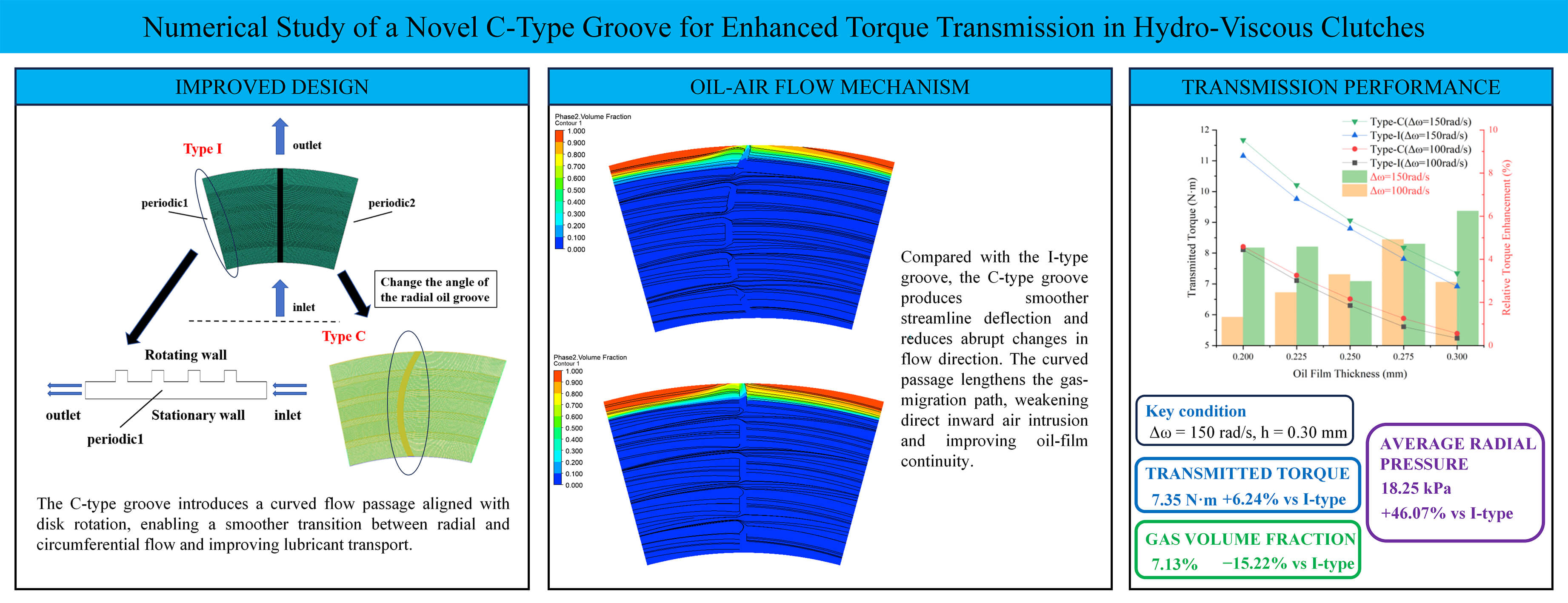
This study investigates the oil-groove configuration of composite friction pairs in hydro-viscous clutches (HVCs), with particular emphasis on the effects of gas content and pressure within the oil film on torque transmission under high-slip conditions. A novel C-type composite groove is proposed to improve oil-film distribution and pressure within the friction interface. A three-dimensional gas–liquid two-phase CFD model is developed to account for the effects of radial groove geometry under prescribed flow-rate and slip conditions. The coupled gas-liquid two-phase Navier–Stokes equations are solved numerically to examine the oil-phase distribution and its influence on torque transmission for different groove geometries, oil-film thicknesses, and slip speeds. The results show that, at a given slip speed and oil-film thickness, the C-type groove maintains a higher average circumferential pressure without changing the groove cross-sectional profile, while increasing oil-film coverage and suppressing negative-pressure regions. At a slip speed of 150 rad/s and an oil-film thickness of 0.3 mm, the C-type groove increases the transmitted torque by 6.24%, reduces the gas volume fraction by 15.22%, and increases the average radial pressure by 46.07% compared with the I-type groove. Under the same operating conditions, the average circumferential pressure remains positive for the C-type groove, whereas it becomes negative for the I-type groove. Moreover, the reduction in transmitted torque associated with gas–liquid two-phase flow is 12.42% lower for the C-type groove than for the I-type groove. These results demonstrate that groove geometry directly affects gas–liquid distribution, pressure within the oil film, and torque transmission at the friction interface. The C-type groove therefore provides a promising approach for improving torque transmission in HVC friction pairs and offers useful numerical guidance for groove design and optimization.Graphic Abstract
Keywords
Due to the complex surrounding rock environment, rock mass shrinkage and deformation, as well as insufficient breakout torque, cutterhead jamming incidents frequently occur in Tunnel Boring Machine (TBM) construction [1,2,3,4,5]. TBM cutterhead jamming can cause substantial construction delays and economic losses, and severe cases may require changes in excavation methods [1,2,3,4,5,6]. These engineering challenges highlight the need to improve breakout torque and restart capability during tunneling operations. A new drive scheme based on coordinated control of hydro-viscous clutch (HVC) and a variable-frequency motor has been proposed. Without increasing the drive-system power, this scheme raises breakout torque, so a jammed cutterhead no longer requires manual intervention. The working principle mainly relies on shear of the oil film across the friction interface. Torque control is achieved by adjusting the oil-film thickness or by altering the pressure-field distribution on the friction disk. Therefore, investigating the groove geometry of the friction interface is of great importance for elucidating the mechanisms that enhance hydro-viscous transmission performance.
Numerous studies have investigated the influence of groove geometry on the transmission performance of HVC friction pairs. Mansouri et al. [7] experimentally analyzed parameters affecting engagement processes such as engagement time and maximum torque, and pointed out that the factors exerting the greatest influence on engagement time are the relative rotational speed and the rate of change of engagement pressure. Xie et al. [8] investigated the effects of rotational speed, oil flow rate, and film thickness on the two-phase flow regime and transmission torque of a hydro-viscous clutch at high rotational speeds. Aphale et al. [9] performed numerical simulations of oil film behavior using computational fluid dynamics software, and through experimental comparison analyzed the transmission characteristics when the clearance between friction pairs was less than 0.1 mm. Jang et al. [10] comprehensively considered heat transfer between friction plates and heat dissipation within the oil film, and developed a thermal conduction model to determine the effects of surface roughness, relative rotational speed, and groove structures on the power output of the friction pair. Haidak et al. [11] compared the groove microstructure of axial piston pump pistons to obtain optimal lubrication groove parameters and their effects. Liao et al. [12] reformulated the governing Navier–Stokes framework and revised the conventional torque-estimation expression by incorporating the combined influence of radial throughflow and rotational inertial effects, thereby proposing a new viscous-torque model. Liao et al. [13] investigated the influence of friction plate groove structures on oil film characteristics and optimized an improved friction plate design using the response surface method. Dong et al. [14] added two types of core-shell particles into copper based friction materials to analyze the wear behavior. Under two-phase flow conditions, this study examines the torque-transfer mechanism of composite grooves in HVC, focusing on how groove geometry shapes the local flow behavior and the transmitted torque. Physically, this study can be interpreted as a thin oil film under rotation, subject to circumferential shear, radial throughflow, flow disturbance from grooves, and changing interface between oil and gas phases. Consequently, this problem falls into the class of rotating disk flows, Couette-Poiseuille-like shear flows, and two-layer viscosity-stratified flows. In relation to these problems, Klingl et al. [15] studied absolute and convective instabilities in throughflow between two closely placed rotating disks; Cheng et al. [16] discussed the stability problem of generalized Couette-Poiseuille flow; and Ma et al. [17] explored the viscosity-stratification instability in generalized Couette-Poiseuille flow of two layers. Related CFD studies of closely spaced rotating disks have also shown that disk spacing and rotational conditions can significantly influence the internal flow field and viscous momentum transfer [18]. While a dedicated linear stability analysis is not performed in this study, these works provide a useful physical basis for understanding the evolution of the predicted oil film and the torque-transfer mechanism in HVC.
The groove design of the friction plate plays an important role in the HVC output torque and in maintaining oil-film uniformity. In the simulation study of two-phase flow, Wang et al. [19] analyzed the influence of multiphase flow on the pump. Their findings help inform studies of complex two-phase flow systems. Cho [20] investigated a novel extended boundary model and compared single-phase and multiphase flows of the oil film between friction plates, finding that at higher rotational speeds, the torque reduction caused by multiphase flow was more pronounced. Takagi et al. [21] studied the effect of gas–liquid coexistence on clutch torque transmission through three-dimensional fluid simulations and single-disc wet clutch two-phase flow experiments. Jammulamadaka et al. [22] constructed a 3D CFD representation of the clutch to quantify the torque loss associated with shear-induced cavitation during power transmission. Zhang et al. [23] examined how groove-layout variations affect cavitation behavior in parallel thrust bearings by comparing the Reynolds equation and the JFO (Jakobsson-Floberg-Olsson) cavitation model. Xie et al. [24] established a multiphase flow model of the oil film based on cavitation effects, analyzing the radial distribution of pressure and temperature at different rotational speeds under varying conditions. Xie et al. [25], combining theoretical and numerical methods, analyzed the impact of friction plate surface grooves on the distribution of oil between friction plates and on torque transmission, in search of methods to enhance torque transfer. Many scholars studied the relationship between oil groove structure and cavitation, analyzed the cavitation position under different structures, and provided theoretical and technical support for preventing oil film cavitation [26,27]. Some other scholars have studied the microtexture of friction plate surface and friction plate materials to improve the performance of HVC [28,29]. However, conventional single radial groove structures exhibit obvious performance limitations. Such grooves often result in uneven oil film distribution, making the formation of local low-pressure zones more likely and thereby significantly increasing the risk of oil film rupture. At the same time, the relatively simple flow path of the oil limits the ability to regulate the pressure field within the film, which constrains further improvements in torque transmission capacity. Therefore, exploring and designing composite groove structures with superior oil flow control capability has become a key direction for enhancing clutch performance.
Analyses of existing studies on the friction plates of HVCs indicate that the groove structure of the friction plate plays a critical role in oil film performance. However, in-depth investigations of the transmission characteristics of oil films in composite groove structures under complex two-phase flow conditions remain relatively limited. This study takes the friction plates with composite groove structures of HVCs under TBM breakout conditions (corresponding to the high slip condition of the clutches) as the research object, with a focus on groove cross-sectional shapes. Unlike traditional single-groove structures or composite groove designs that merely alter groove shapes, this work compares different groove structure parameters without changing the groove cross-sectional geometry. Particular emphasis is placed on examining the flow-field characteristics associated with different groove configurations under varying rotational speeds, different film-thickness settings, and a fixed inlet flow rate. This study specifically focuses on the high-slip operating condition representative of shield machine breakout conditions, in which the driving plate rotates while the driven plate remains stationary. Therefore, the conclusions made in this research are more relevant to this specific operational condition. The findings shed light on the effects that groove geometry has on oil film stability and torque transfer efficiency at high slip values due to cutter head breakout.
During operation of a hydro-viscous speed-regulating clutch, the working-oil flow rate required at the friction interface increases as the rotational speed and thickness increase. The onset of two-phase flow between the friction plates can cause the oil film to contract. In the actual application process, the lubricating oil flow supplied by the hydraulic system is typically maintained at a fixed level. Therefore, it is assumed that once the oil film ruptures, the remaining film contracts, so that the friction pair is no longer in the fully flooded (full-film) shear regime. At this time, the fluid between the friction plates is no longer entirely oil, but a portion of gas penetrates into the inter-plate gap. Considering the influence of surface tension, the shape of the oil film will gradually change, as shown in Fig. 1.
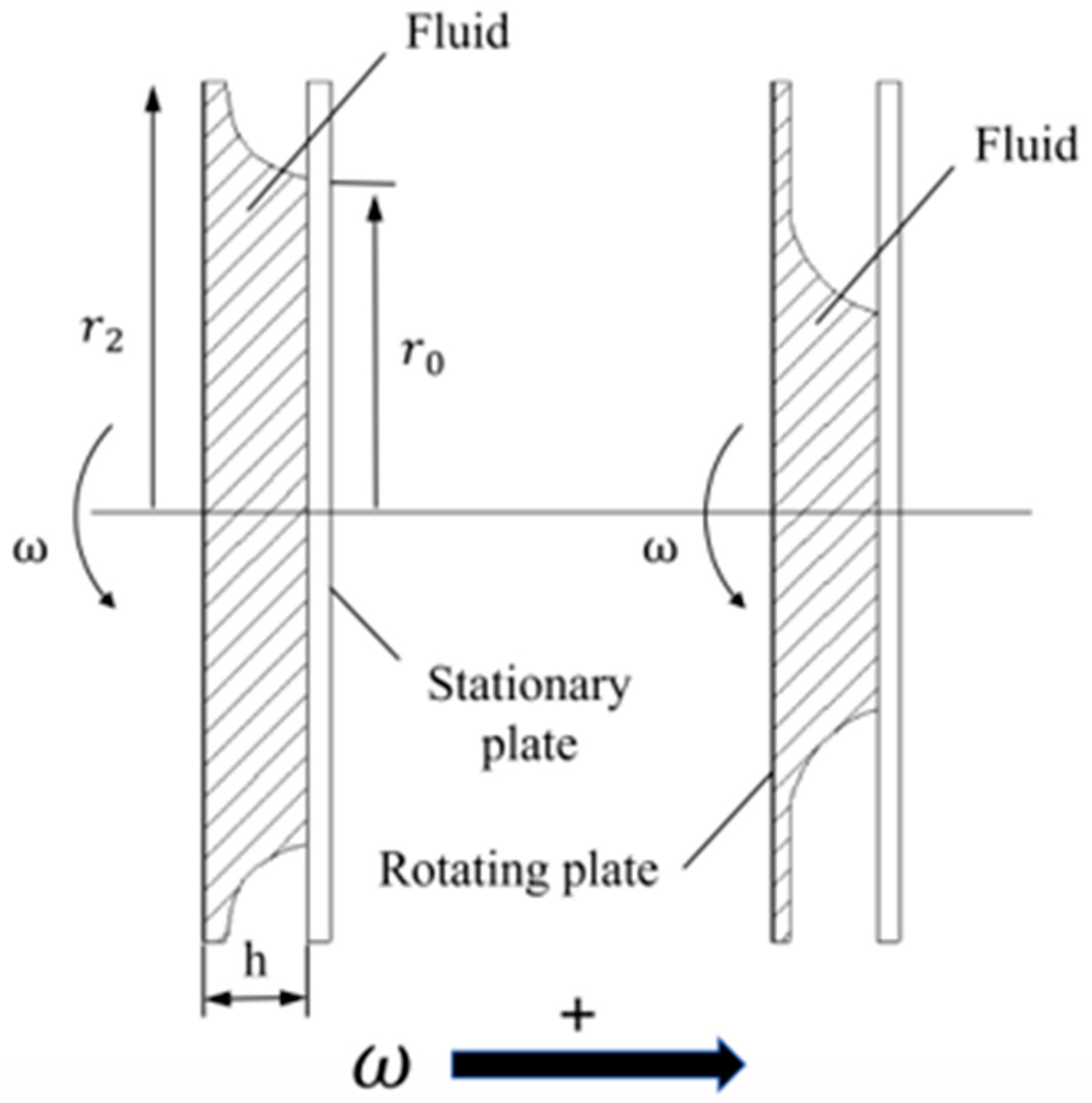
Figure 1: Change of oil film morphology.
2.1 Working Principle of the HVC
The fundamental physical characteristics of the viscous clutch are schematically shown in Fig. 2. The basic operating principle of the HVC is that lubricating oil is thrown out from the centrifugal chamber and discharges through the clearance between the driving and driven plates, forming an annular oil film. Torque is transmitted through this disk-like lubricant film between the friction pairs. The circulation of lubricating oil is maintained by a pump, which ensures a constant flow rate at the inlet.
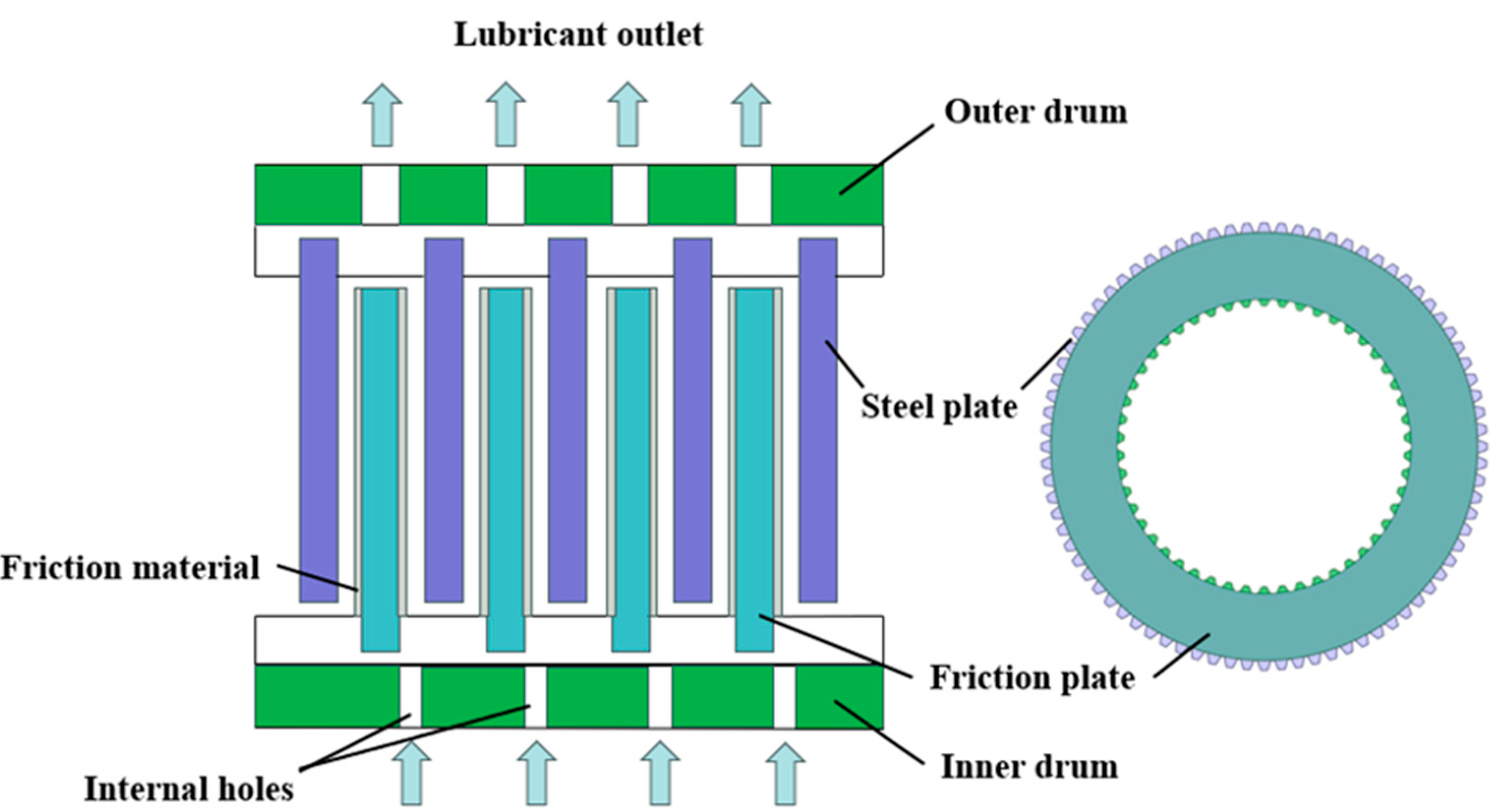
Figure 2: Flow process of oil in the viscous clutch.
Since an HVC friction unit is formed by a stack of driving and driven plates arranged in an alternating sequence, a simplified physical model is established for clarity. A single friction pair composed of a driving plate, a driven plate, and an interfacial oil film is selected as the research object, as the oil film formed between the plates can be approximated as an annular shape [30]. The torque transmission model of the HVC, as illustrated in Fig. 3, can be derived through integration and expressed as follows [31]:
In the formula, (
In the present study, a single friction pair consisting of one driving plate, one driven steel plate, and one interfacial oil-film layer is considered. Therefore, n = 1 is used in Eq. (1) and in all subsequent theoretical–numerical torque comparisons. With n = 1, Eq. (1) gives the theoretical torque transmitted by one complete friction pair under the ideal fully flooded single-phase oil-film condition. This value is used as the reference torque for evaluating the torque reduction caused by gas intrusion and oil-film rupture under the oil–gas two-phase-flow conditions. For an actual HVC containing
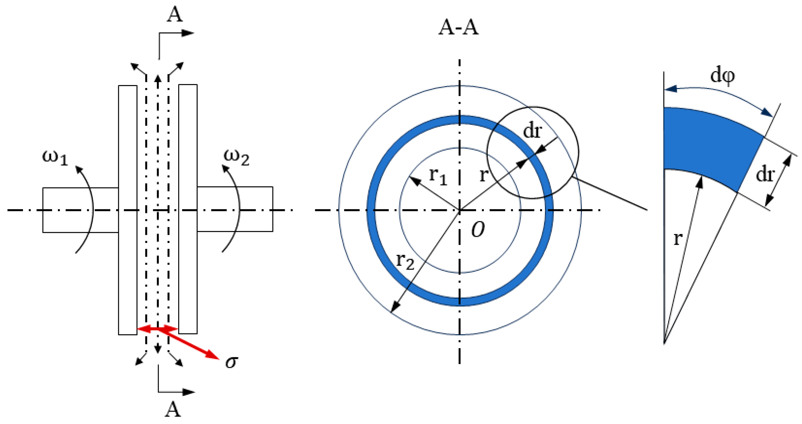
Figure 3: Torque calculation model.
2.2 Physical Model and Computational Domain
The C-type composite groove adopted in this study is an evolution of the traditional single-groove structure. Initially, a single radial groove was employed, which was simple to manufacture; however, under two-phase flow conditions, the oil film was prone to rupture, resulting in poor film formation capability. To improve oil distribution and enhance film coverage, circumferential grooves were introduced, giving rise to the radial composite groove. Nevertheless, the conventional radial composite groove exhibits structural symmetry, which leads to large areas of air intrusion on the rotating side, thereby limiting its effectiveness in suppressing gas entry. To address this issue, the structure was further optimized into a C-type composite groove, in which the leading and trailing edges are connected to the inner and outer radii at a 60° arc. The left and right boundaries of the C-type groove are circular arcs with identical radii of 50 mm and an arc angle of 60°. The groove width and depth are 3 mm and 0.3 mm, respectively. The C-shaped groove was developed to allow the oil to move along a channel that would follow the circumferential direction caused by the rotational movement of the disks. This design is different from the conventional I-shape groove in that the curved profile allows for better oil movement from the inner radius to the outer radius and reduces sudden ingress of gases into the grooved area. The arc is aligned with the rotation direction of the friction pair, thereby enhancing the shear action of the oil film and improving flow-field stability. This configuration is better suited to torque transmission under thicker oil-film and two-phase-flow conditions. Using the clutch configuration shown in Fig. 1, a flow-domain model was developed. In this work, the fluid region between one friction pair was selected as the study domain. To shorten the runtime, a periodic one-twelfth sector model of the inter-pair flow field was built in 3D CAD software by exploiting circumferential periodicity in the rotational direction; Table 1 lists the structural parameters.
Table 1: Structural parameters of the model.
| Parameter | Value | Unit |
|---|---|---|
| Internal diameter | 220 | mm |
| External diameter | 320 | mm |
| Number of grooves | 12 | piece |
| Trench width | 3 | mm |
| Trench depth | 0.3 | mm |
To ensure uniformity in the evaluation of groove structures, the number of grooves for both C-groove and I-groove composite grooves was kept constant at 12. Other geometric parameters, such as the number of slots, the curvature, the width and depth of the slots, remain unchanged.
The computational domain represents the oil-air flow region between the rotating friction plate and the stationary plate. The lubricating oil is introduced from the mass flow inlet and the outlet is defined as pressure outlet, which is open to atmospheric pressure and air is backflow phase. The top surface rotates, bottom wall is fixed, and both circular walls have been set as periodic boundary conditions.
2.3 VOF Formulation and Governing Equations
The oil-air two-phase flow within the friction-pair clearance is modeled using the Volume of Fluid (VOF) method [32]. Lubricating oil is treated as the primary phase, whereas air is treated as the secondary phase. The oil-phase volume fraction is denoted by α = α0, and the corresponding air-phase volume fraction is
The VOF model was selected because the present study primarily focuses on the local oil-air volume-fraction distribution and its influence on the pressure field and torque transmission within the thin friction-pair clearance. Compared with the Euler-Euler model, which requires separate momentum equations for the two phases together with additional interphase momentum-exchange closure relations, the VOF model solves a shared momentum equation coupled with the volume-fraction transport equation, thereby reducing the computational complexity. The Mixture model is more suitable for multiphase flows in which the relative slip between phases is of primary interest. Therefore, the VOF model is considered appropriate for the objectives of the present study.
In the absence of interphase mass transfer, the volume-fraction transport equation for the secondary air phase is expressed as
Within the VOF framework, the local mixture properties appearing in the shared governing equations depend on the phase volume fraction. For the present oil-air system, the mixture density, dynamic viscosity, and thermal conductivity are expressed as
Mass conservation equation:
Momentum conservation equation:
Energy conservation equation:
To provide a theoretical interpretation of oil-film contraction and rupture, an analytical model was introduced as a supplementary analysis. For conciseness, the simplified derivation and the final expression for the equivalent rupture radius are provided in Appendix A.
2.4 Mesh Generation and Grid-Independence Study
The three-dimensional geometry was imported into ICEM CFD, and the fluid domain was discretized using a structured hexahedral mesh. Fig. 4 shows the mesh configuration of the computational domain. Since the mesh resolution can affect the numerical results, a grid-independence study was conducted by systematically refining the mesh.
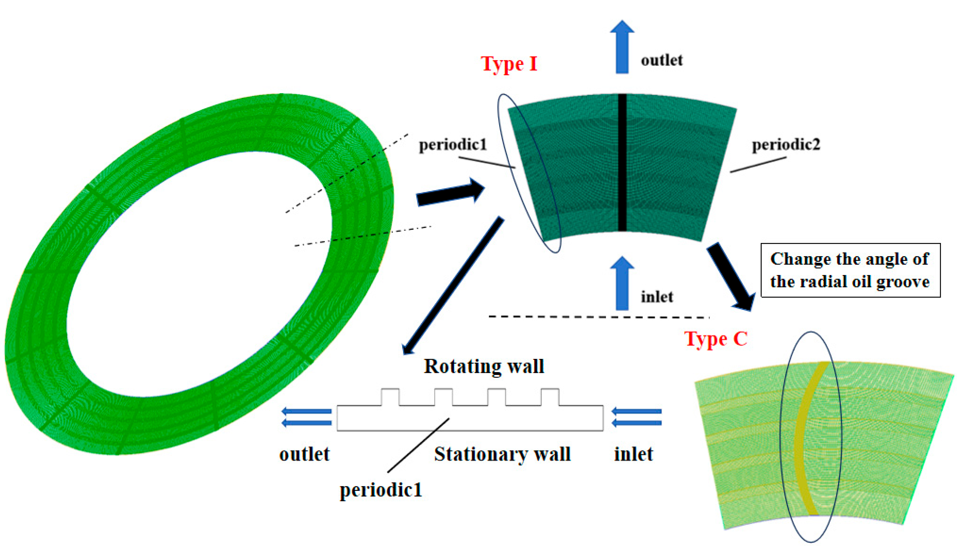
Figure 4: 3D flow field mesh.
Since the number of mesh nodes significantly affects the simulation results, the oil film mesh was refined, and a grid independence test was conducted, as shown in Fig. 5. Ultimately, Scheme 5 was selected, with 28 mesh nodes and a total of 354,952 elements. A summary of the mesh configuration is provided in Table 2.
The mesh independence analysis was primarily conducted based on transmitted torque, which was the principal performance metric considered in this study.
Table 2: Mesh division data table.
| Serial Number | Radial | Tangential | Axial | Number of Meshes | |
|---|---|---|---|---|---|
| Groove Region | Non-Groove Region | ||||
| 1 | 70 | 20 | 100 | 28 | 128,232 |
| 2 | 140 | 20 | 100 | 21 | 207,423 |
| 3 | 140 | 30 | 120 | 21 | 264,993 |
| 4 | 112 | 30 | 120 | 28 | 278,616 |
| 5 | 140 | 30 | 120 | 28 | 354,952 |
| 6 | 140 | 40 | 130 | 28 | 410,722 |
| 7 | 154 | 40 | 130 | 28 | 454,870 |
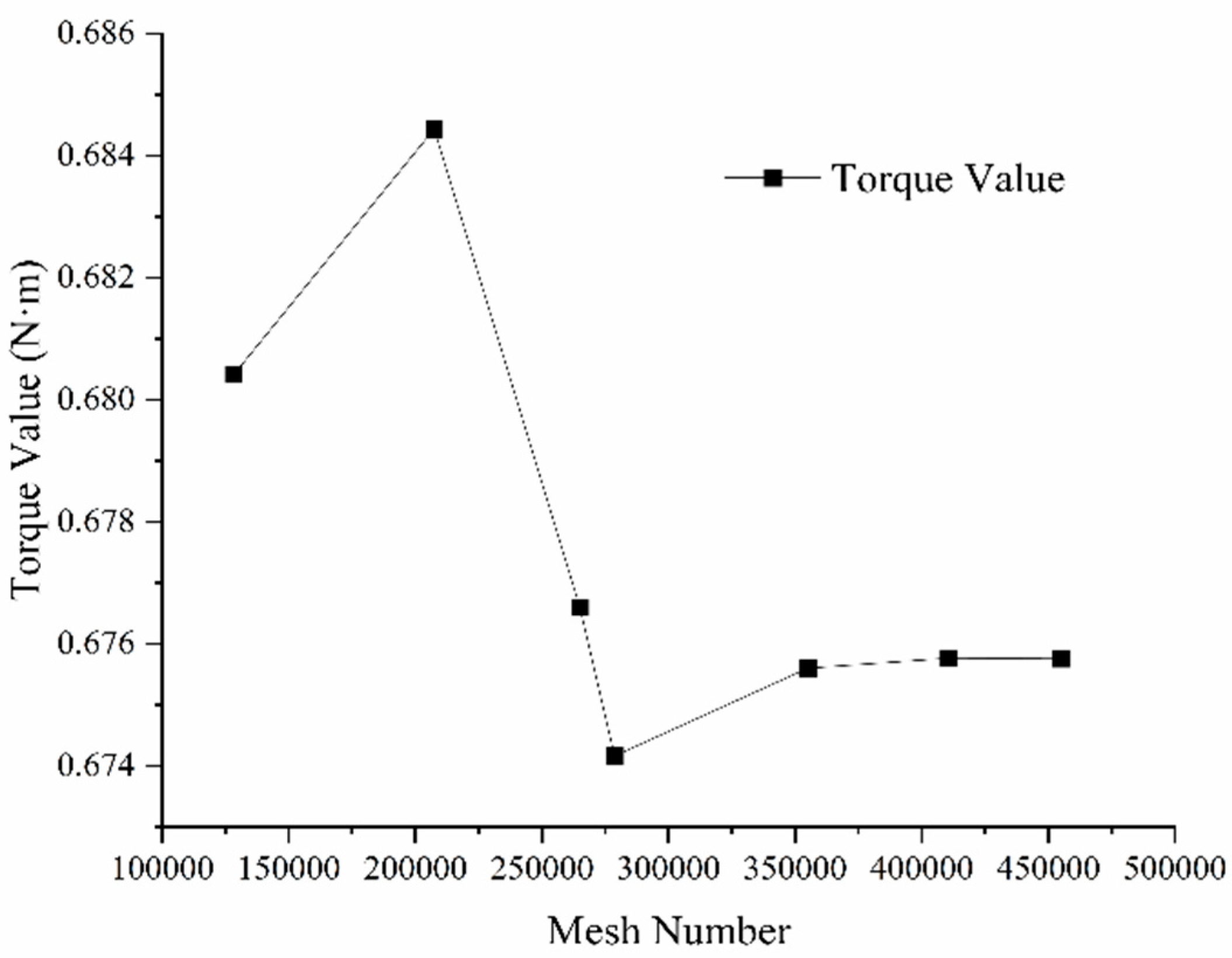
Figure 5: Line chart of torque corresponding to mesh number.
2.5 Numerical Method, Boundary Conditions, and Flow-Regime Assessment
To determine whether a turbulence model is required, the flow regime within the friction-pair clearance was assessed based on the Reynolds number. According to the near-disk flow theory for a rotating plate, the Reynolds number based on the tangential velocity at the outer radius is defined as (
Based on the above Reynolds-number analysis, the flow at 100 rad/s is classified as laminar, whereas that at 150 rad/s is identified as an unstable laminar state. Accordingly, the investigated operating conditions were treated using the laminar model, and no additional turbulence model was activated.
The oil-air two-phase flow was solved using the VOF model described in Section 2.3, with lubricating oil treated as the primary phase and air as the secondary phase. The governing equations described in Section 2.3 were discretized using the finite-volume method [33] and solved using the double-precision, pressure-based solver in ANSYS Fluent. Pressure-velocity coupling was achieved using the SIMPLE algorithm [33]. The gradients were evaluated using the Least-Squares Cell-Based method, and the pressure field was interpolated using the Body-Force-Weighted scheme [34]. The momentum and energy equations were discretized using the second-order upwind scheme, whereas the volume-fraction transport equation was discretized using the first-order upwind scheme. All simulations were performed in steady-state mode, and the pseudo-transient method was not activated. Therefore, no physical temporal discretization or physical time-step size was employed, and time-step selection is not applicable to the present calculations.
The inlet was prescribed as a mass-flow-rate inlet. The outlet communicated with the atmosphere and was specified as a pressure outlet with zero gauge pressure, with air specified as the backflow phase. The upper boundary represented the rotating driving plate and was imposed as a rotating-wall condition, whereas the lower boundary represented the stationary steel plate and was specified as a stationary no-slip wall. The circumferential boundaries of the one-twelfth computational sector were treated as periodic boundaries. Surface-tension effects at the oil-air interface were included using the CSF model described in Section 2.3 [35]. The oil-air surface-tension coefficient was set to 0.03 N/m, and the wall contact angle was specified as 9°. The energy equation was enabled to account for viscous heating generated by the strong shear within the thin oil film, while no external volumetric heat source was imposed. The operating parameters used in the simulations are listed in Table 3.
Numerical convergence was assessed jointly using the scaled residual histories, the inlet-outlet mass-flow balance, and representative physical monitors. The target residual levels were set to 10−3 for the continuity equation, 10−5 for the momentum equations, and 10−6 for the energy equation. In addition, the relative mass-flow imbalance between the inlet and outlet was required to remain below 0.5%. For some two-phase cases, the residuals approached stable plateaus without fully reaching their prescribed target values. When the residual histories remained stable, the mass-flow imbalance was below 0.5%, and the monitored gas volume fraction, pressure, and transmitted torque showed no noticeable variation with further iterations, the solution was considered to have reached a quasi-steady state.
Table 3: Material properties and operating parameters.
| Parameter | Value | Unit |
|---|---|---|
| Oil density | 851 | kg/m3 |
| Oil dynamic viscosity | 0.026 | Pa·s |
| Oil specific heat | 2131 | J/(kg·K) |
| Oil thermal conductivity | 0.138 | W/(m·K) |
| Air density | 1.225 | kg/m3 |
| Air dynamic viscosity | 1.7894 × 10⁻⁵ | Pa·s |
| Air specific heat | 1006.43 | J/(kg·K) |
| Air thermal conductivity | 0.0242 | W/(m·K) |
| Mass flow rate inlet | 0.00338 | kg/s |
| Surface tension coefficient | 0.03 | N/m |
| Wall surface contact angle | 9 | ° |
| Oil film thickness | 0.2~0.3 | mm |
| Friction plate speed | 100, 150 | rad/s |
| Steel plate speed | 0 | rad/s |
To explore the influence exerted by two-phase flow on the hydro-viscous drive behaviors of clutch friction pairs, numerical simulations were performed for the oil films of the C-type composite groove and the I-type composite groove under the aforementioned conditions.
3.1 Analysis of Two-Phase Oil Film Distribution
Fig. 6 shows the oil-air distribution for both composite groove geometries on the surface of the steel plate with an oil film thickness of 0.2, 0.225, 0.25, 0.275, and 0.3 mm where the friction disc is rotated at 100 rad/s while the steel plate remains fixed. The oil-air distribution for both groove geometries is similar for the five operating conditions. Oil is discharged mainly through the grooved regions, whereas air enters the contact primarily through the land regions and gradually expands along the direction of rotation. As the oil-film thickness increases, the oil-covered region generally decreases, while the main distribution characteristics remain essentially unchanged.
For the C-type composite groove, the oil-covered area gradually decreases from 3440.512 mm2 at an oil-film thickness of 0.2 mm to 3310.382 mm2 at 0.3 mm, while the corresponding coverage ratio decreases from 97.3% to 93.7%. For the I-type composite groove, the oil-covered area generally decreases from 3354.713 to 3223.487 mm2, and the coverage ratio decreases from 94.9% to 91.2%, with slight fluctuations during this process.
Generally, there exist certain differences between the two types of grooves regarding oil film coverage. In all five different cases of oil film thickness, the oil film coverage area in case of C-type composite grooves is greater than that of the I-type composite grooves. The difference is most pronounced at an oil-film thickness of 0.275 mm, where the coverage ratio of the C-type composite groove is approximately 4.41% higher, indicating that groove geometry influences the oil-air two-phase distribution within the friction interface.
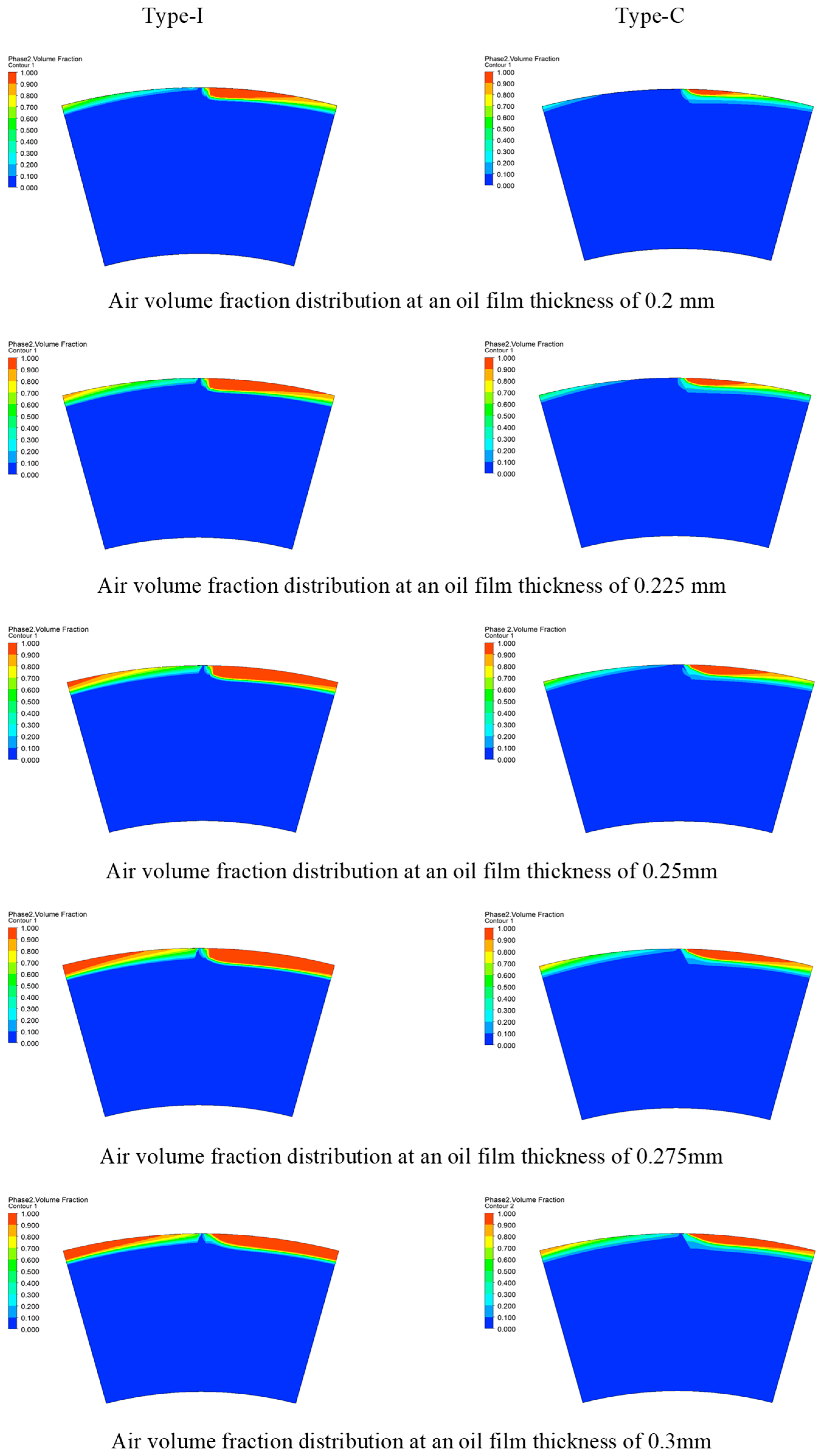
Figure 6: Contour plot of oil–gas distribution under different oil film thicknesses (∆ω = 100 rad/s).
Fig. 7 presents the oil-air distributions on the steel-plate surface for the two composite groove configurations at oil-film thicknesses of 0.2, 0.225, 0.25, 0.275, and 0.3 mm, with the friction disc rotating at 150 rad/s and the steel plate remaining stationary. As the oil-film thickness increases, the gas phase gradually expands within the land regions, while the oil-film coverage decreases. For the I-type composite groove, the oil-covered area decreases from 3165.587 to 2968.169 mm2, and the coverage ratio decreases from 89.6% to 84.0%. For the C-type composite groove, the corresponding values decrease from 3270.967 to 3084.715 mm2 and from 92.5% to 87.3%, respectively.
Compared with the results at 100 rad/s in Fig. 6, increasing the rotational speed to 150 rad/s markedly reduces the oil-film coverage of both groove configurations. At an oil-film thickness of 0.2 mm, the covered area of the I-type composite groove decreases from 3354.713 to 3165.587 mm2, corresponding to a reduction of 5.64%, while its coverage ratio decreases from 94.9% to 89.6%. For the C-type composite groove, the covered area decreases from 3440.512 to 3270.967 mm2, representing a reduction of 4.93%, and the coverage ratio decreases from 97.3% to 92.5%. Meanwhile, the gas phase expands rapidly within the land regions and progressively propagates from the outer radius toward the inner radius. This may be attributed to the enhanced centrifugal-inertial and shear effects at higher rotational speeds, which promote the outward transport of oil and weaken the continuity of oil coverage.
Overall, the two groove configurations exhibit noticeable differences in oil-film coverage. At all five oil-film thicknesses, the C-type composite groove has a larger oil-covered area than the I-type composite groove. At an oil-film thickness of 0.3 mm, its oil-covered area and coverage ratio are both approximately 3.93% higher, indicating that groove geometry has a significant influence on the oil-air two-phase distribution within the friction interface.
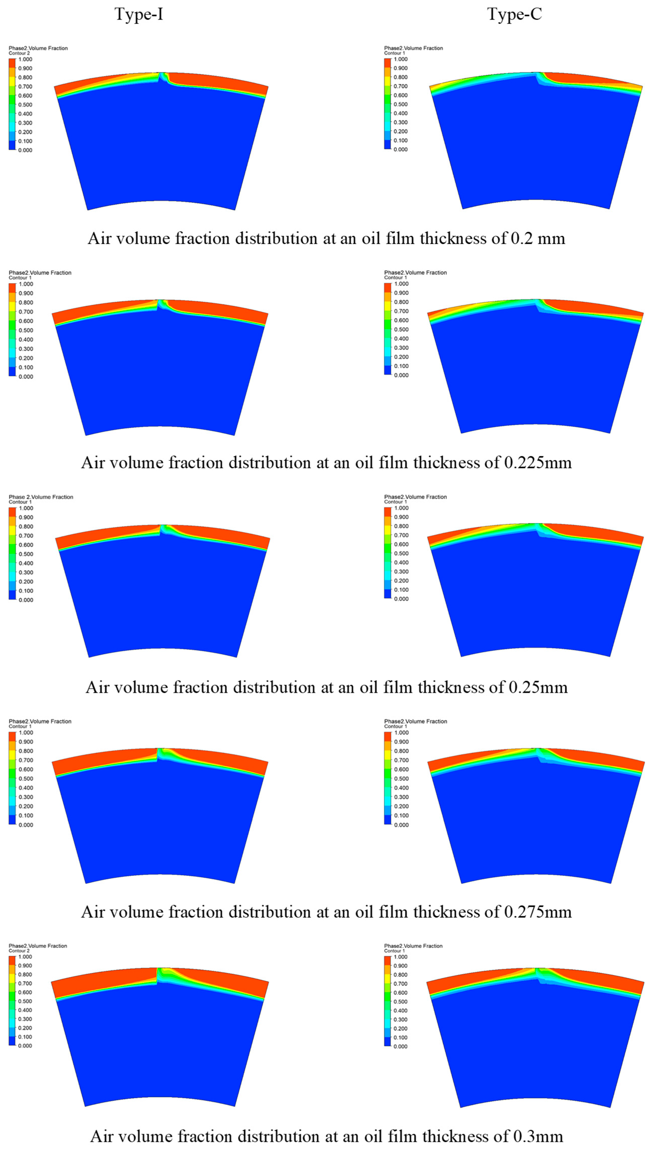
Figure 7: Contour plot of oil–gas distribution under different oil film thicknesses (Δω = 150 rad/s).
Fig. 8 presents the variation in gas volume fraction for the two composite groove configurations at oil-film thicknesses of 0.2, 0.225, 0.25, 0.275, and 0.3 mm. At a speed difference of 100 rad/s, the gas volume fraction of the I-type composite groove generally increases from 2.19% to 4.18%, with a slight fluctuation, whereas that of the C-type composite groove increases from 1.98% to 3.80%. When the speed difference increases to 150 rad/s, the corresponding values increase from 4.67% to 8.41% for the I-type groove and from 3.89% to 7.13% for the C-type groove. Overall, the gas volume fraction shows an increasing trend with oil-film thickness.
At the same oil-film thickness, increasing the speed difference results in a clear increase in gas volume fraction for both groove configurations. At an oil-film thickness of 0.2 mm, for example, the gas volume fraction increases from 2.19% to 4.67% for the I-type composite groove and from 1.98% to 3.89% for the C-type composite groove. This trend is consistent with the oil-air distributions shown in Fig. 6 and Fig. 7. Differences are also observed between the two groove configurations, with the C-type composite groove generally exhibiting a lower or comparable gas volume fraction. These results indicate that oil-film thickness, speed difference, and groove geometry all affect the oil-air two-phase distribution within the friction interface.
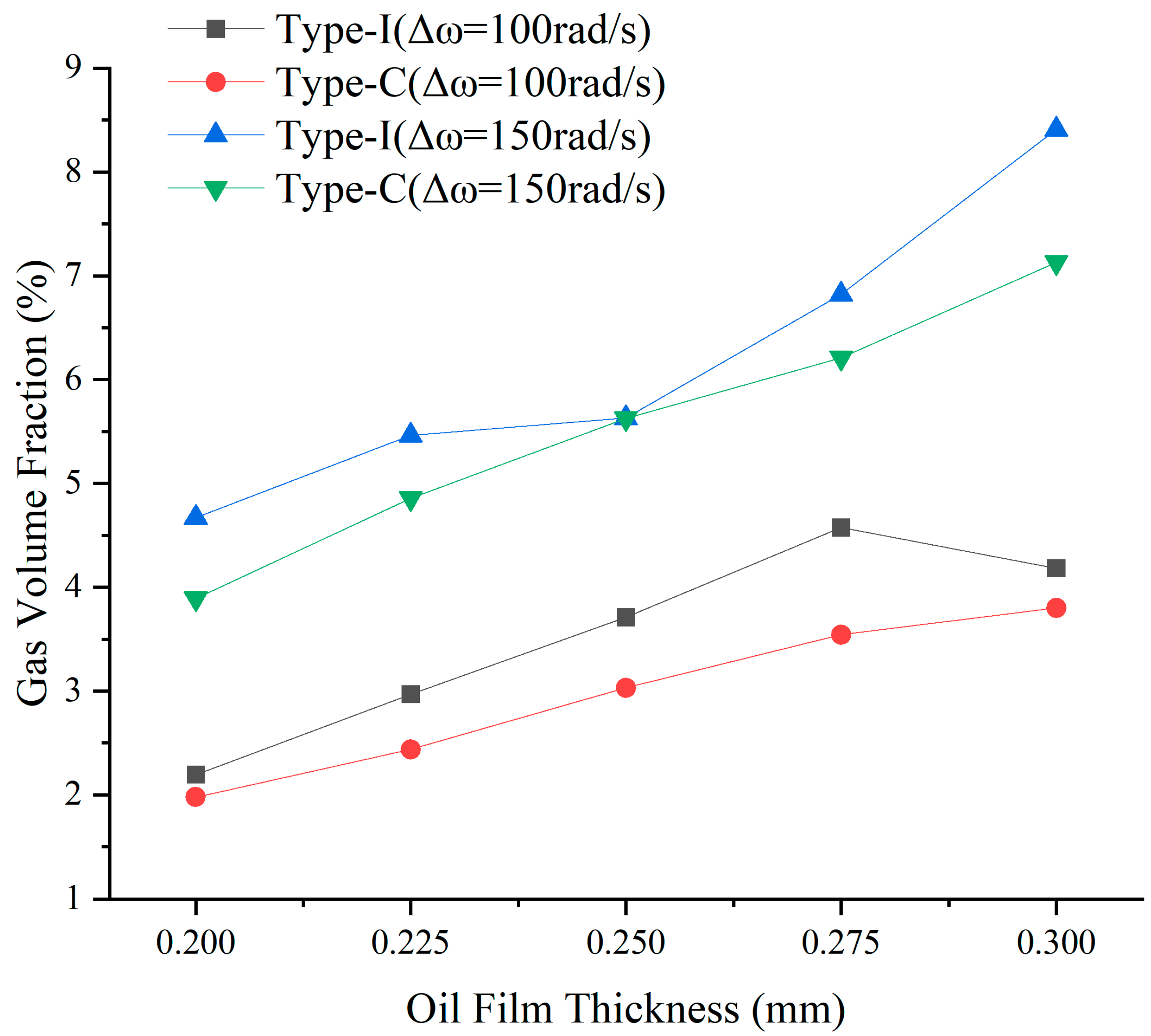
Figure 8: Line chart of gas content versus speed difference and thickness.
3.2 Analysis of Local Flow Structures and Air-Intrusion Mechanism
To analyze the effect of groove geometry on air intrusion further, an operating point corresponding to an oil film thickness of 0.3 mm and slip speed of 150 rad/s was chosen. The comparison between gas volume fraction, velocity vectors, and streamlines on the mid-plane of oil film of the I-groove and C-groove is shown in Fig. 9. The second phase is considered as air, and zones with higher gas volume fraction signify more air intrusion.
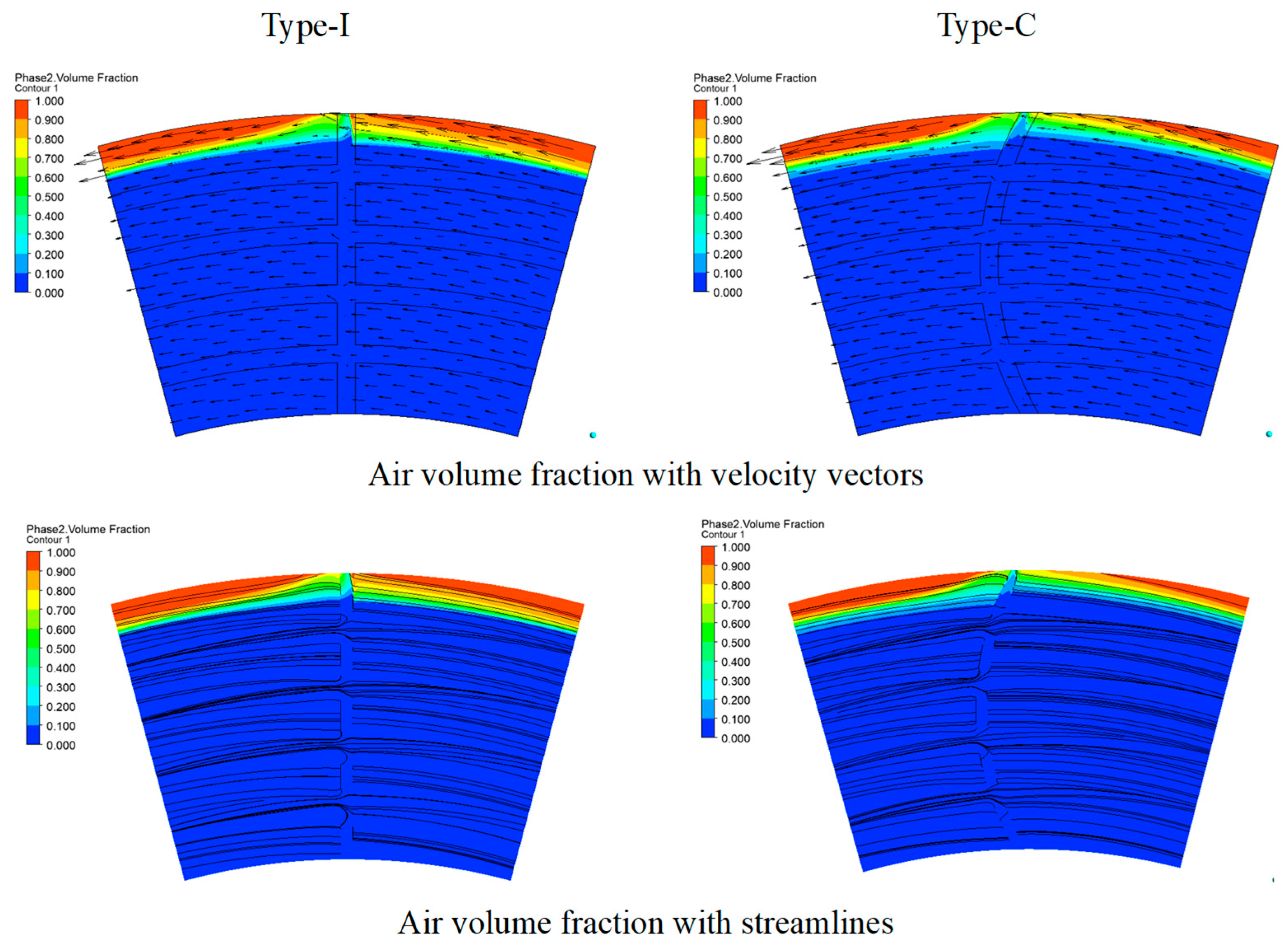
Figure 9: Air-phase distributions and flow structures at the oil-film midplane for I- and C-type composite grooves (h = 0.3 mm, Δω = 150 rad/s).
As is evident from Fig. 9, the gas phase is mostly present in the outer radius of the grooves while the middle and inner radius regions are still mostly filled with oil. The circumferential shear force induced by the rotating wall and the centrifugal force move the lubricant to the outer regions of the system. In case the inflow of the lubricant is not sufficient to make up for the outflow of oil in the system, the oil film continuity at the outer radius becomes weak, and air is allowed to penetrate into the clearance of the friction pair.
In the case of I-type composite groove, the fluid flow takes place through the straight radial groove and changes its direction significantly at the point of contact between the radial and circumferential grooves. The significant difference in the direction between the radial flow and the circumferential flow caused due to the rotation of the wall makes the streamlines bend sharply, creating more disturbance in the local flow region. Moreover, the straight radial groove is a relatively direct link between the outer radius area and the inner part of the oil film. This makes it easy for air to flow through the radial direction into the oil film from the outer radius.
On the other hand, the direction of velocity in the C-shaped groove varies smoothly through the curved flow path, producing a more uniform deflection of streamlines. Since the curvature of the groove is aligned with the rotation of the friction disk, the sudden change from radial flow to circumferential flow may be lessened, thus reducing the possibility of flow separation at the groove interface. The curved passage also causes the gas-migration direction to deviate circumferentially and increases the migration distance from the outer radius toward the inner radius, thereby weakening the direct inward intrusion of air along the radial groove.
Therefore, the C-type composite groove suppresses air entrainment mainly by improving the continuity of the local flow direction and altering the gas-migration path, rather than by reducing the centrifugal effect itself. These results indicate that the curved groove improves the organization of the oil-film flow and helps maintain more continuous liquid-phase coverage, which is consistent with the lower average gas content and higher transmitted torque obtained for the C-type groove.
3.3 Analysis of the Oil Film Pressure Field
Fig. 10 presents the circumferential pressure distributions of the two composite groove configurations along a radial position of 145 mm at different oil-film thicknesses. At a constant speed difference, the circumferential pressure of both groove configurations generally decreases as the oil-film thickness increases from 0.2 to 0.3 mm, with pronounced pressure variations occurring near the groove inlet and outlet. At a constant oil-film thickness, increasing the speed difference from 100 to 150 rad/s further reduces the pressure in the land regions and produces more evident negative-pressure valleys near the groove boundaries. This trend is consistent with the decrease in oil-film coverage and the increase in gas volume fraction shown in Fig. 6, Fig. 7 and Fig. 8. The enhanced centrifugal-inertial and shear effects at the higher speed promote the expansion of the gas phase and redistribute the oil between the grooved and land regions, thereby intensifying the local pressure variations.
At the five oil-film thicknesses, the C-type composite groove generally exhibits higher positive-pressure levels within the groove and in the downstream land region, and this difference becomes more evident at a speed difference of 150 rad/s. Local negative pressure occurs near the groove boundaries for both configurations. At the higher speed difference, the negative-pressure variation is relatively more pronounced for the I-type groove, whereas the pressure downstream of the groove recovers to a relatively higher level for the C-type groove. Combined with the oil-air distributions and gas volume fractions shown in Fig. 6, Fig. 7 and Fig. 8, these results indicate that groove geometry modifies the circumferential pressure distribution and the local oil-air two-phase flow characteristics within the friction interface.
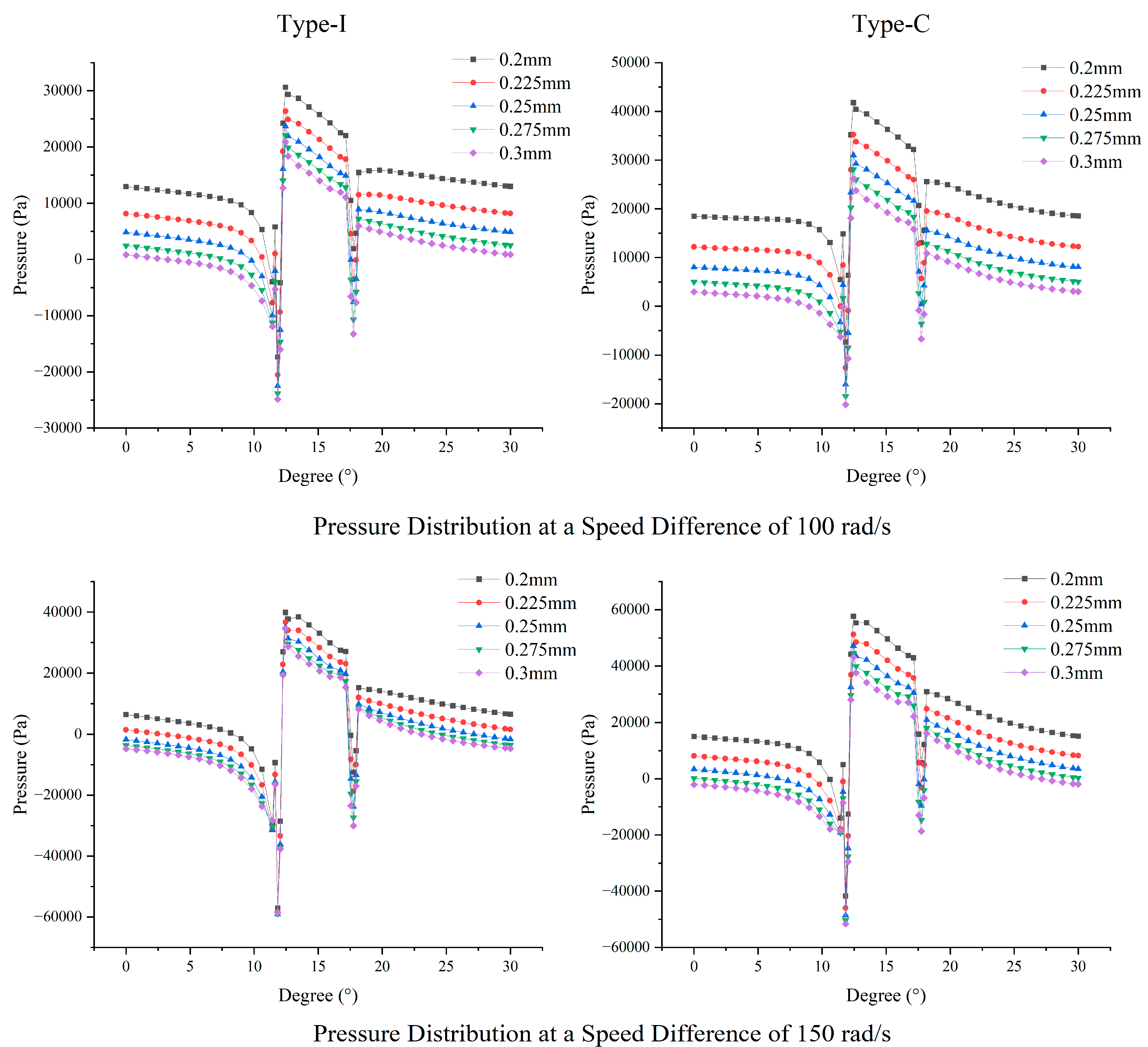
Figure 10: Pressure distribution at z = 0.3 mm, r = 145 mm.
Fig. 11 presents the average circumferential pressures of the two composite groove configurations at z = 0.3 mm and a radius of 145 mm for oil-film thicknesses of 0.2, 0.225, 0.25, 0.275, and 0.3 mm. At both speed differences, the average circumferential pressure decreases with increasing oil-film thickness. At a speed difference of 100 rad/s, the average pressure of the C-type composite groove decreases from 21,954.633 to 5869.987 Pa, corresponding to a reduction of 73.26%, whereas that of the I-type composite groove decreases from 14,371.180 to 2470.053 Pa, representing a reduction of 82.81%. At a speed difference of 150 rad/s, the pressure of the C-type composite groove decreases from 21,236.082 to 3458.378 Pa, corresponding to a reduction of 83.71%. The pressure of the I-type composite groove decreases from 9456.813 Pa and becomes negative at oil-film thicknesses of 0.275 and 0.3 mm, reaching −1683.190 Pa at 0.3 mm.
At the same oil-film thickness, increasing the speed difference also reduces the average circumferential pressure, and this effect becomes more pronounced at larger oil-film thicknesses. For the C-type composite groove, increasing the speed difference from 100 to 150 rad/s reduces the average pressure by 3.27% at 0.2 mm and by 41.08% at 0.3 mm. For the I-type composite groove, the pressure decreases from 14,371.180 to 9456.813 Pa at 0.2 mm, whereas it decreases from 2470.053 to −1683.190 Pa at 0.3 mm. This variation is consistent with the previously observed decrease in oil-film coverage and increase in gas volume fraction.
Differences in average circumferential pressure are also observed between the two groove configurations. At 100 rad/s, the average pressure of the C-type composite groove is 52.77%–137.65% higher than that of the I-type composite groove. At 150 rad/s, the C-type composite groove maintains a positive average pressure over all five oil-film thicknesses, whereas negative values occur for the I-type composite groove at the larger film thicknesses.
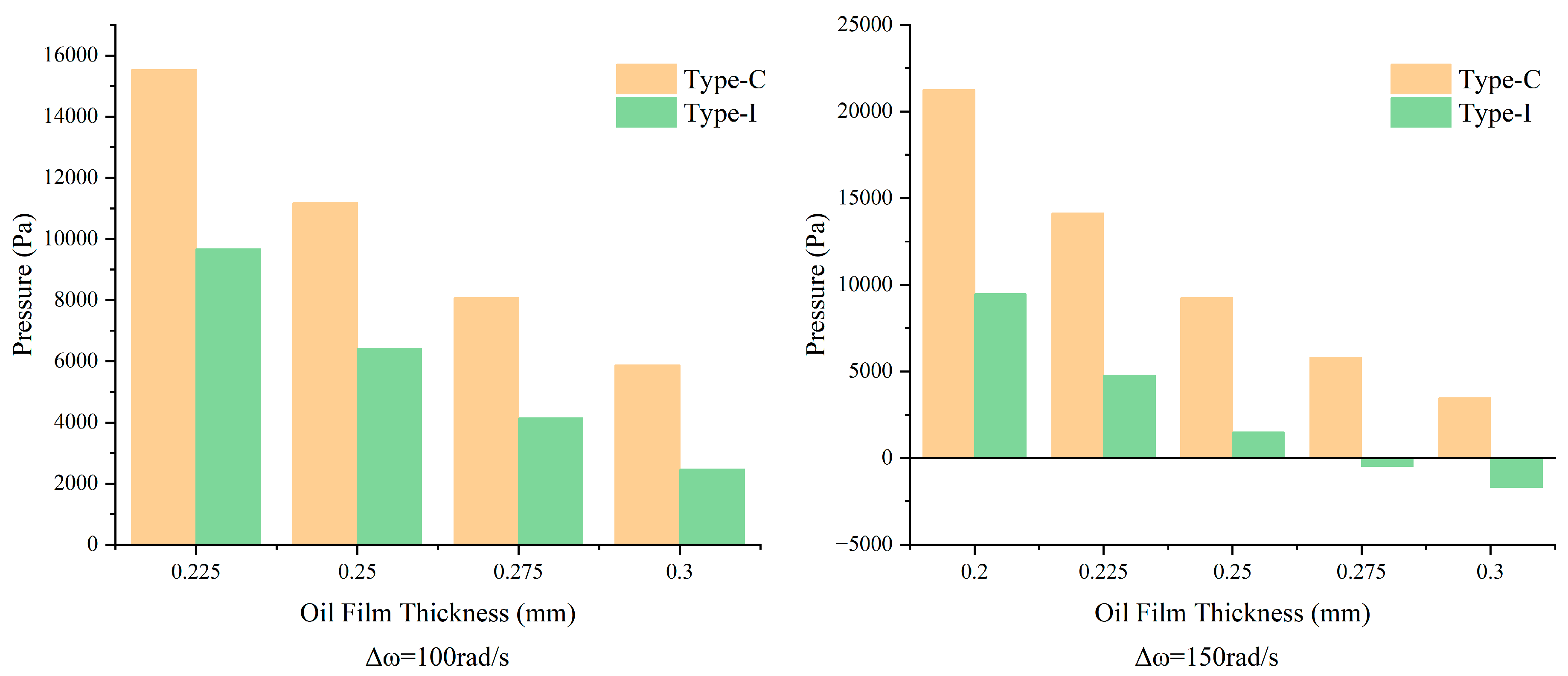
Figure 11: Line chart of average circumferential pressure.
Fig. 12 presents the radial pressure distribution curves of the oil films formed by the two types of composite-groove friction plates. The oil pressure exhibits noticeable fluctuations when flowing through the circumferential groove regions. At different oil film thicknesses, the radial pressure within the oil film decreases with increasing radius. With the oil film thickness kept constant, the pressure inside the oil grooves increases with the rise of rotational speed. Compared with the I-type composite groove, the C-type composite groove generally exhibits a higher pressure within the groove regions under the investigated conditions. Together with the oil–gas distribution results presented above, this pressure characteristic indicates that the two groove configurations exhibit distinct pressure and oil–gas two-phase-flow responses within the friction interface.
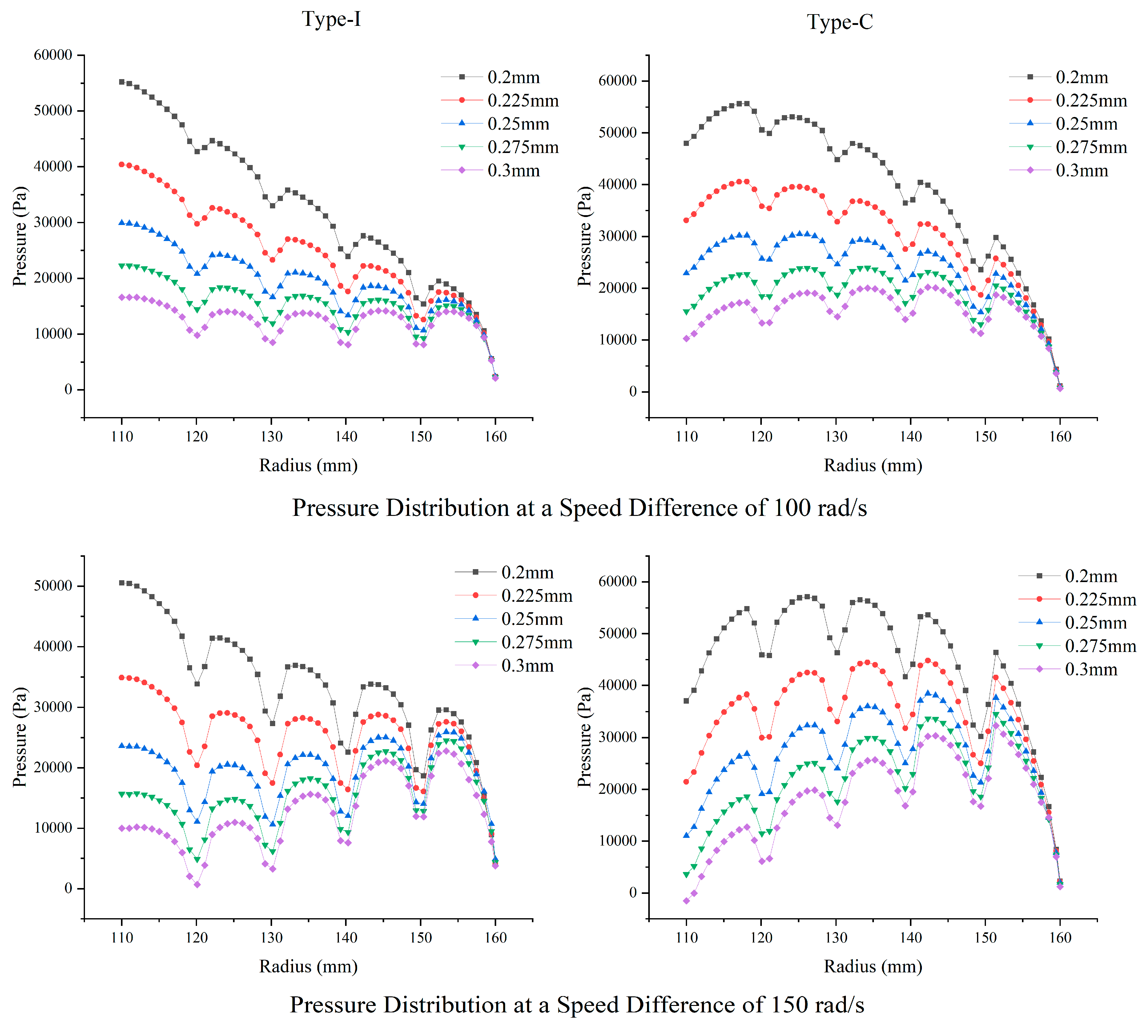
Figure 12: Line chart of radial pressure profiles for two types of composite oil-grooved friction discs.
Following the circumferential-pressure analysis, Fig. 13 further presents the average radial pressures of the two composite groove configurations at different oil-film thicknesses. At a constant speed difference, the average radial pressure of both configurations decreases with increasing oil-film thickness. At a speed difference of 100 rad/s, the average radial pressures of the C-type and I-type composite grooves decrease from 40,165.03 and 32,671.90 Pa to 15,900.50 and 12,500.07 Pa, respectively. As the oil-film thickness increases, the relative pressure difference between the C-type and I-type grooves gradually increases from 22.93% to 27.20%.
When the speed difference increases to 150 rad/s, the average radial pressures of the C-type and I-type composite grooves decrease from 45,428.37 and 33,670.80 Pa to 18,246.60 and 12,491.96 Pa, respectively. Meanwhile, the relative pressure difference between the two configurations increases from 34.92% to 46.07% with increasing oil-film thickness.
In contrast to the decrease in average circumferential pressure shown in Fig. 10, increasing the speed difference from 100 to 150 rad/s raises the average radial pressure of the C-type composite groove at all oil-film thicknesses, whereas only a limited change is observed for the I-type groove. As the oil-film thickness increases, the radial-pressure difference between the two configurations becomes more pronounced, indicating a stronger radial-pressure response of the C-type groove to the higher speed difference.
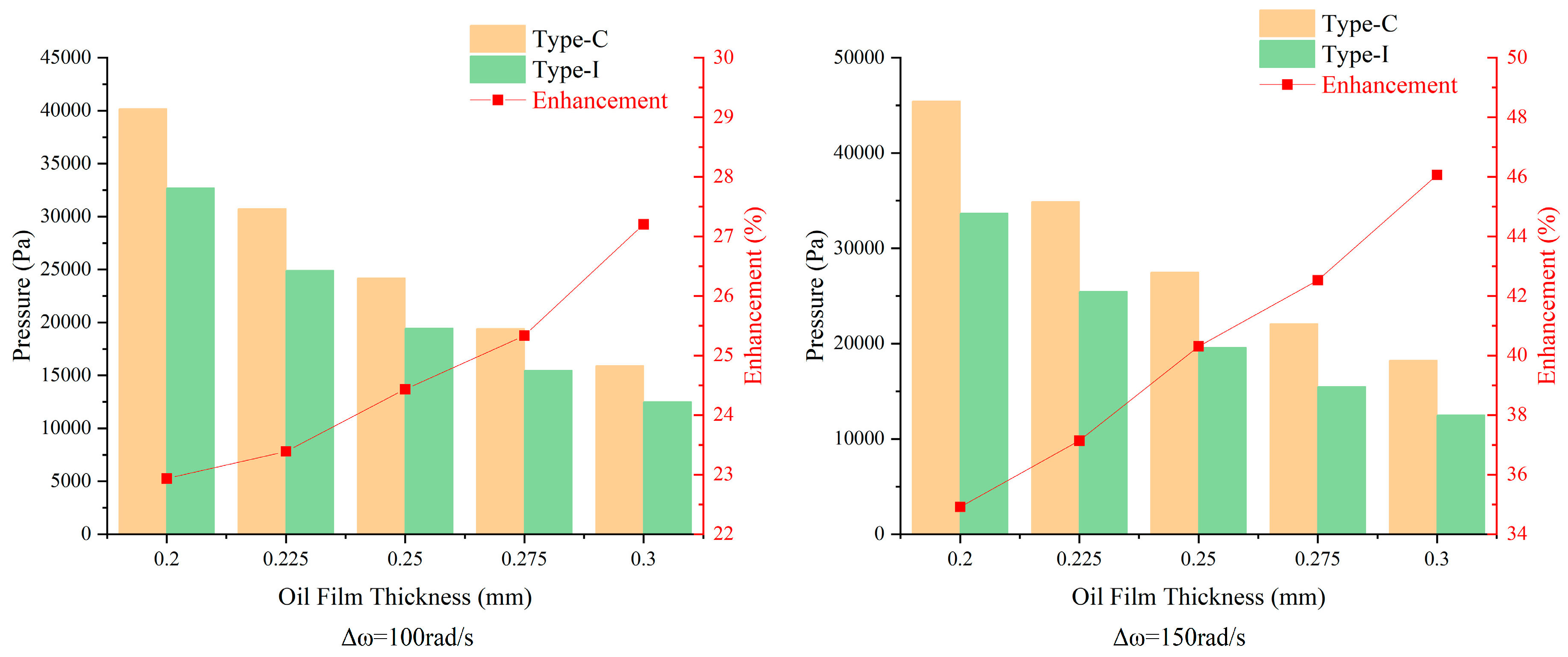
Figure 13: Line chart of average radial pressure.
3.4 Analysis of Transmission Torque
Friction plates with different groove structures have different torque transmission characteristics. TBM cutterhead extrication typically demands high breakout torque, and the benefits of a high-capacity plate become increasingly apparent as the transmitted torque rises. This makes groove optimization a central task when designing composite-groove structures for friction pairs operating in complex flows. In HVC, torque transmission capability is a key indicator of transmission reliability. Under the action of two-phase flow, the flow regime and shear behavior of the interfacial oil film can change markedly, posing substantial challenges to conventional composite groove designs. Higher torque and heavy loading also impose stricter requirements on groove-structure design. Therefore, increasing torque becomes especially important when the oil film is relatively thick and in a two-phase flow state. A detailed analysis of the flow field within the grooves, oil supply characteristics, pressure distribution, and suppression of gas regions under these conditions is crucial for designing friction pair structures that can stably and efficiently transmit high torque even under high-slip clutch conditions. Torque measured at various interfaces from CFD analysis as seen in Fig. 14 is the result of integration of viscous shear stresses exerted by oil films on the surfaces being driven. Local shear stress was calculated based on velocity gradients in the oil film layer, whereas the contribution of gas was insignificant in relation to torque production. It means that torque measurement is a result of interactions between oil-film integrity, gas content, and flow field features.
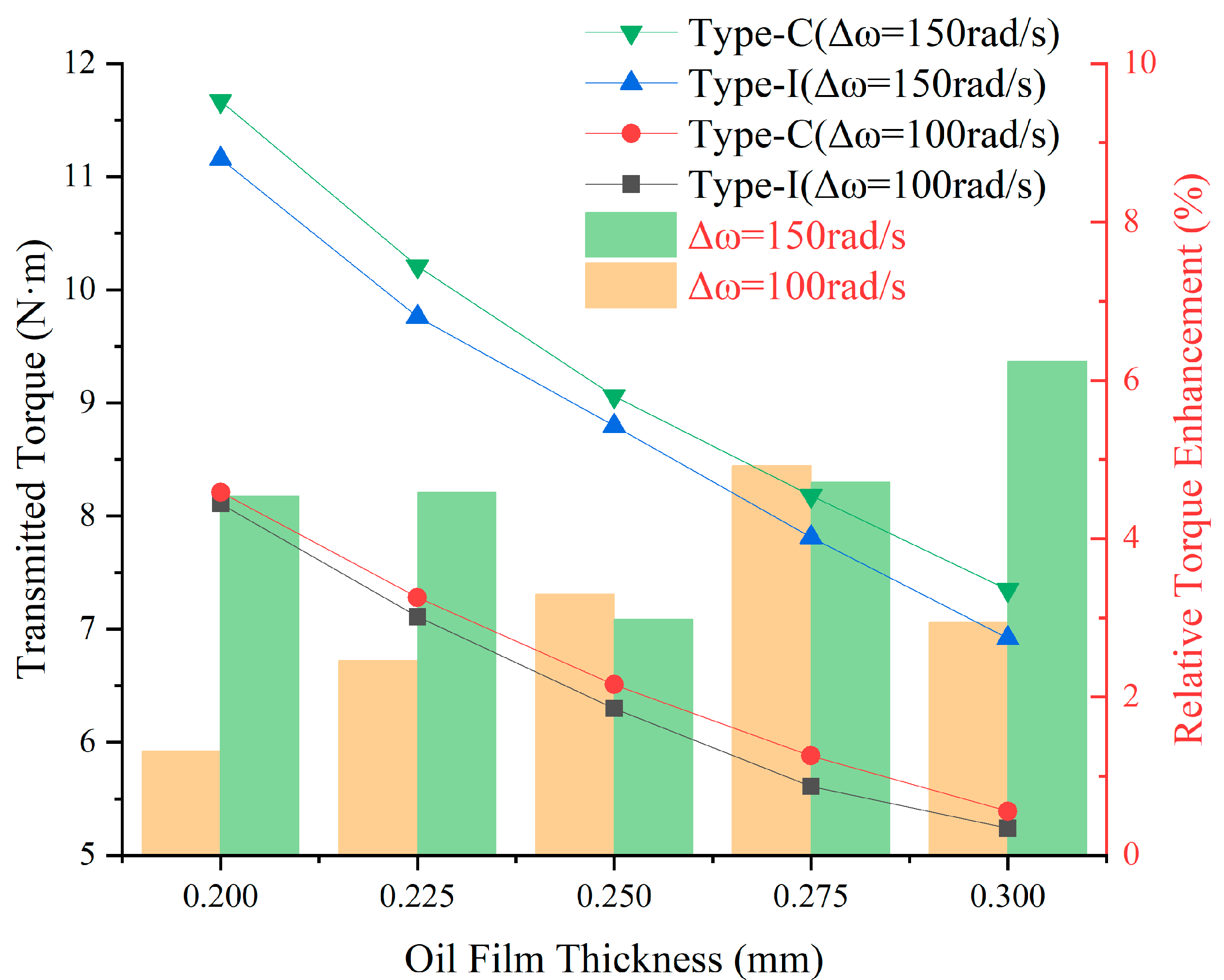
Figure 14: Line chart of torque variation and enhancement along oil film thickness direction.
As illustrated in Fig. 14, the transmission torque increases significantly with decreasing oil-film thickness. Under a slip condition of Δω = 100 rad/s, the torques of the C-type composite groove are 8.21, 7.28, 6.51, 5.88, and 5.39 N·m at oil-film thicknesses of 0.2, 0.225, 0.25, 0.275, and 0.3 mm, respectively, representing increases of approximately 1.32%, 2.46%, 3.30%, 4.92%, and 2.94% compared with the I-type composite groove. Under a slip condition of Δω = 150 rad/s, the corresponding torques of the C-type composite groove are 11.67, 10.21, 9.06, 8.18, and 7.35 N·m, which are approximately 4.54%, 4.58%, 2.98%, 4.71%, and 6.24% higher than those of the I-type composite groove, respectively.
Under both Δω = 100 rad/s and Δω = 150 rad/s conditions, the transmitted torque decreases as the oil-film thickness increases. At Δω = 150 rad/s, the transmission torque of the C-type composite groove increases from 7.35 to 11.67 N·m as the oil-film thickness decreases from 0.3 to 0.2 mm, corresponding to an increase of approximately 58.81%. These results demonstrate that groove structure has a significant impact on torque transmission. In particular, under high slip and a relatively thick oil film of 0.3 mm, the C-type composite groove transmits 6.24% more torque than the I-type composite groove. Combined with the higher groove pressure shown in Fig. 12 and Fig. 13, the lower gas volume fraction and larger oil-film coverage shown in Fig. 6 and Fig. 8, these torque results provide consistent evidence that the C-type composite groove can improve oil-film integrity and torque-transmission performance under the investigated high-slip conditions.
Fig. 15 compares the theoretical torque calculated from Eq. (1) using n = 1 with the CFD-predicted torque under oil–gas two-phase-flow conditions.
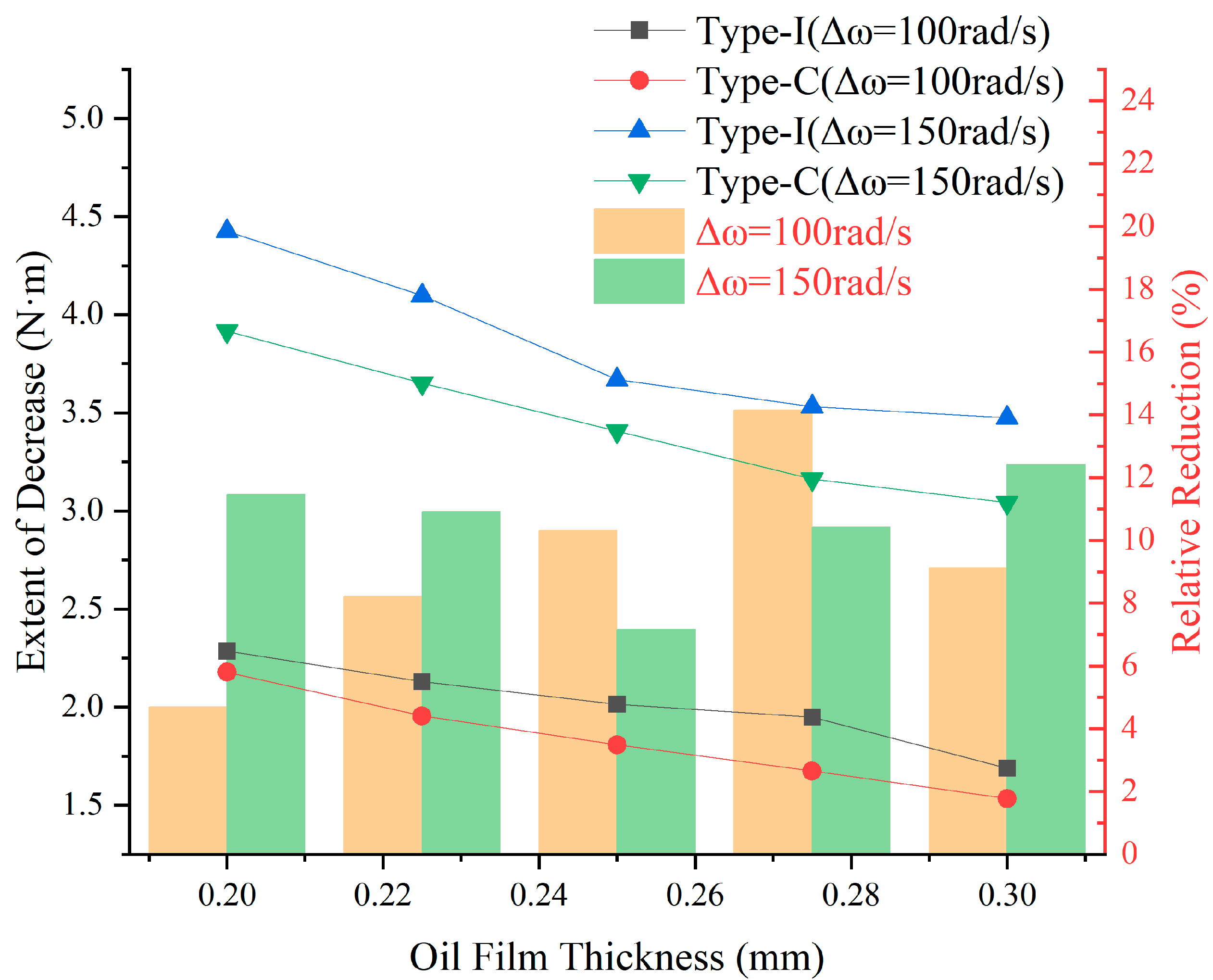
Figure 15: Line chart of torque reduction along oil film thickness under comparison of two-phase flow and theoretical pure oil film conditions.
The theoretical torque calculated from Eq. (1) with n = 1 corresponds to one complete friction pair under the ideal fully flooded single-phase oil-film condition. By comparing this theoretical torque with the CFD-predicted torque under oil–gas two-phase-flow conditions, the torque reduction caused by gas intrusion and oil-film rupture can be evaluated.
As shown in Fig. 15, the oil–gas two-phase flow reduces the viscous torque of both composite groove configurations at oil-film thicknesses of 0.2, 0.225, 0.25, 0.275, and 0.3 mm. Moreover, the absolute torque reduction becomes more pronounced as the speed difference increases. This trend is consistent with the higher gas volume fraction shown in Fig. 8 and the reduction in oil-film coverage shown in Fig. 6 and Fig. 7 at the higher speed difference.
At Δω = 100 rad/s, the torque reductions of the I-type composite groove are 2.29, 2.13, 2.02, 1.95, and 1.69 N·m at the five oil-film thicknesses, respectively, whereas those of the C-type composite groove are 2.18, 1.96, 1.81, 1.67, and 1.53 N·m. Compared with the I-type groove, the corresponding torque reductions of the C-type groove are lower by 4.69%, 8.22%, 10.30%, 14.14%, and 9.13%, respectively. The largest relative difference at this speed difference occurs at an oil-film thickness of 0.275 mm.
When the speed difference increases to Δω = 150 rad/s, the torque reductions of the I-type composite groove are 4.42, 4.10, 3.67, 3.53, and 3.47 N·m, whereas those of the C-type composite groove are 3.92, 3.65, 3.41, 3.16, and 3.04 N·m, respectively. The corresponding reductions of the C-type groove are 11.46%, 10.90%, 7.16%, 10.42%, and 12.42% lower than those of the I-type groove. In particular, at an oil-film thickness of 0.3 mm, the torque reduction of the C-type composite groove is 12.42% lower than that of the I-type composite groove.
Combined with the transmitted-torque results in Fig. 14, these results show that increasing the speed difference raises the actual transmitted torque through enhanced shear, while also enlarging its deviation from the ideal fully flooded single-phase value. At all five oil-film thicknesses, the C-type groove exhibits a smaller torque reduction than the I-type groove. This result is consistent with its larger oil-film coverage, lower gas volume fraction, and distinct pressure characteristics, indicating that groove geometry affects the attenuation of viscous torque under oil–gas two-phase-flow conditions.
A comprehensive investigation was conducted on the design and flow characteristics of composite-groove friction plates under two-phase flow conditions. The main conclusions are as follows:
- 1.A three-dimensional oil-gas two-phase CFD modeling has been developed to study the flow mechanism of composite groove friction couples at high slip operation. Based on the findings, a distinct stratified flow mechanism is observed in the oil film at the interface, where lubricant flows out through grooves and gas enters through the non-groove zones.
- 2.Compared with the conventional I-type composite groove, the proposed C-type composite groove improves oil-film continuity and suppresses gas intrusion under the investigated two-phase-flow conditions. This groove structure maintains relatively higher circumferential and radial pressures, reduces negative-pressure regions, and increases oil-film coverage.
- 3.Considering the studied case of high slipping regime, the groove C type demonstrates a slightly greater torque transfer compared to the groove I type. In particular, at Δω = 150 rad/s and h = 0.30 mm, its transmitted torque was 6.24% higher, its gas volume fraction was 15.22% lower, and its average radial pressure was 46.07% higher than those of the I-type groove. Under the same condition, the average circumferential pressure of the C-type groove remained positive, whereas that of the I-type groove became negative, revealing distinct oil–gas two-phase-flow and pressure characteristics between the two configurations.
- 4.The present study focuses on high-slip operating conditions representative of TBM breakout scenarios. From the findings, it can be observed that the C-type composite groove can help in improving torque loss at severe two-phase flow conditions. It should be noted that the numerical analysis was based on a single friction pair using a one-twelfth periodic model, with a prescribed oil-supply condition and fixed groove number, width, depth, and curvature parameters. The investigated flow range mainly covers laminar and unstable-laminar conditions. Therefore, the present conclusions are primarily applicable to the specified model configuration and operating range. Their applicability to different oil-supply conditions, other groove dimensions, multiple friction pairs, and transient or turbulent flow conditions requires further investigation.
- 5.As an engineering-oriented and foundational investigation of hydro-viscous clutch friction pairs under the high-slip conditions associated with TBM cutterhead breakout, the present study mainly employs steady-state CFD simulations to evaluate the overall effects of composite-groove configuration on oil-air distribution, pressure characteristics, and transmitted torque. Dedicated two-phase-flow bench tests have not yet been conducted. Therefore, the predicted gas volume fraction, pressure, and transmitted torque should be interpreted as comparative numerical results under the investigated conditions. The main uncertainties arise from numerical diffusion of the VOF interface, idealized boundary conditions, the steady-state assumption, and constant fluid properties. In addition, the microscopic coupling among local groove curvature, flow separation, vortex structures, and gas-phase transport has not yet been systematically resolved. Future work will combine two-phase-flow bench tests, flow-visualization experiments, and high-resolution transient simulations to validate the numerical model and further reveal the local fluid-dynamic mechanisms by which the C-type groove regulates oil-air two-phase flow.
Acknowledgement:
Funding Statement: This work was supported by the Natural Science Foundation of Hunan Province of China (2025JJ70310), the Research Foundation of Education Bureau of Hunan Province of China (23A0620), and Jiangsu University of Technology Graduate Practice and Innovation Plan Project (XSJCX25_78).
Author Contributions: Xiangping Liao: Data curation; Ye Xu: Writing–original draft; Ying Zhao: Software; Langxin Sun: Formal analysis. All authors reviewed and approved the final version of the manuscript.
Availability of Data and Materials: The data that support the findings of this study are available from the corresponding author upon reasonable request.
Ethics Approval: Not applicable.
Conflicts of Interest: Given his role as Guest Editor of this journal, Xiangping Liao had no involvement in the peer review of this article and had no access to information regarding its peer review. Full responsibility for the editorial process for this article was delegated to another journal editor. The authors declare no other conflicts of interest.
The analytical model presented in this appendix is developed for an ungrooved and axisymmetric oil film between two parallel disks. The lubricant is assumed to be incompressible and Newtonian, the oil-film thickness is uniform, and the circumferential variation of the flow field is neglected. The model is intended to provide a reduced-order description of oil-film contraction and to estimate the equivalent rupture radius. It is not directly coupled with the three-dimensional VOF model used for the composite-groove friction pairs.
Under the thin-film assumption, the radial and circumferential momentum equations are reduced to
The no-slip boundary conditions are
The mean radial velocity is related to the volumetric flow rate by
A successive-approximation procedure is adopted to account for the inertial effects. The zero-order velocity field is first obtained by neglecting the inertia terms. The resulting radial and circumferential velocity components are then substituted into Eq. (A1). After integration across the oil-film thickness and application of Eq. (A2), the radial pressure gradient can be written as
Under the classical Reynolds rupture condition adopted in this reduced-order model, the radial pressure gradient vanishes at the equivalent rupture radius
Substituting this condition into Eq. (A3) and selecting the physically admissible positive root yields
It should be emphasized that Eqs. (A1)–(A4) are established for an ungrooved and circumferentially uniform oil film. The model does not explicitly describe the local three-dimensional flow, circumferential pressure fluctuations, mass exchange between the groove and land regions, or non-axisymmetric gas intrusion induced by the composite grooves. Therefore, the analytical model is used only to interpret the general oil-film contraction mechanism. The detailed oil-gas distribution, pressure field, and torque-transmission characteristics of the C-type and I-type composite grooves are obtained from the three-dimensional VOF simulations.
References
1. Cui G , Ke X . Rescue technology of the jamming accident for the double-shield TBM in complex geological conditions: a case study. Alex Eng J. 2023; 79: 374– 89. doi:10.1016/j.aej.2023.08.032. [Google Scholar] [CrossRef]
2. Lin P , Yu T , Xu Z , Shao R , Wang W . Geochemical, mineralogical, and microstructural characteristics of fault rocks and their impact on TBM jamming: a case study. Bull Eng Geol Environ. 2022; 81( 1): 64. doi:10.1007/s10064-021-02548-0. [Google Scholar] [CrossRef]
3. Lin P , Xiong Y , Xu Z , Wang W , Shao R . Risk assessment of TBM jamming based on Bayesian networks. Bull Eng Geol Environ. 2022; 81: 47. doi:10.1007/s10064-021-02511-z. [Google Scholar] [CrossRef]
4. Xu ZH , Wang WY , Lin P , Nie LC , Wu J , Li ZM . Hard-rock TBM jamming subject to adverse geological conditions: influencing factor, hazard mode and a case study of Gaoligongshan Tunnel. Tunn Undergr Space Technol. 2021; 108: 103683. doi:10.1016/j.tust.2020.103683. [Google Scholar] [CrossRef]
5. Huang X , Liu Q , Peng X , Lei G , Liu H . Mechanism and forecasting model for shield jamming during TBM tunnelling through deep soft ground. Eur J Environ Civ Eng. 2019; 23( 9): 1035– 68. doi:10.1080/19648189.2017.1327895. [Google Scholar] [CrossRef]
6. Du LJ . Progress, challenges and countermeasures of TBM construction technology in China. Tunnel Constr. 2017; 37( 9): 1063– 75. (In Chinese). [Google Scholar]
7. Mansouri M , Holgerson M , Khonsari MM , Aung W . Thermal and dynamic characterization of wet clutch engagement with provision for drive torque. J Tribol. 2001; 123( 2): 313– 23. doi:10.1115/1.1329856. [Google Scholar] [CrossRef]
8. Xie F , Zheng X , Tong Y , Zhang B , Guo X , Wang D , et al. Effect of two-phase flow on transmission torque of oil film at high rotational speeds. Ind Lubr Tribol. 2018; 70( 8): 1367– 73. doi:10.1108/ilt-10-2017-0311. [Google Scholar] [CrossRef]
9. Aphale CR , Cho J , Schultz WW , Ceccio SL , Yoshioka T , Hiraki H . Modeling and parametric study of torque in open clutch plates. J Tribol. 2006; 128( 2): 422– 30. doi:10.1115/1.2162553. [Google Scholar] [CrossRef]
10. Jang JY , Khonsari MM , Maki R . Three-dimensional thermohydrodynamic analysis of a wet clutch with consideration of grooved friction surfaces. J Tribol. 2011; 133: 011703. doi:10.1115/1.4003019. [Google Scholar] [CrossRef]
11. Haidak G , Kou J , Wei X , Kengne E , Wang D . Numerical investigation on suitable micro-groove structure for improved efficiency between piston and cylinder in axial piston machine. Mech Based Des Struct Mach. 2026; 54( 1): 2540465. doi:10.1080/15397734.2025.2540465. [Google Scholar] [CrossRef]
12. Liao X , Sun L , Kang S , Liu K , Zhao Y , Zhu X . Investigation and revision of the viscous torque formula based on inertial effects and nonlinear dissipative effects. Phys Fluids. 2025; 37( 7): 073629. doi:10.1063/5.0276382. [Google Scholar] [CrossRef]
13. Liao X , Zhao Y , Sun L , Zhu X . Parametric optimization design method for friction plates of hydro-viscous clutches. J Vis Exp. 2025;( 221): e68328. doi:10.3791/68328. [Google Scholar] [CrossRef]
14. Dong Y , Ma B , Xiong C , Zhao Q , Chen H , Zhang Y , et al. Tribological and wear properties of Cu-based composite reinforced by core–shell structure in multi-disk clutch. Tribol Lett. 2024; 72( 3): 66. doi:10.1007/s11249-024-01844-6. [Google Scholar] [CrossRef]
15. Klingl S , Lecheler S , Pfitzner M . Absolute and convective stability of flow between closely spaced co-rotating disks with imposed throughflow. Eur J Mech Fluids. 2022; 91: 226– 32. doi:10.1016/j.euromechflu.2021.10.012. [Google Scholar] [CrossRef]
16. Cheng W , Ma H , Pullin DI , Luo X . Linear stability analysis of generalized Couette–Poiseuille flow: the neutral surface and critical properties. J Fluid Mech. 2024; 995: R3. doi:10.1017/jfm.2024.611. [Google Scholar] [CrossRef]
17. Ma H , Pullin DI , Zhang Y , Ding J , Cheng W , Luo X . Viscosity stratification instability in two-layer, generalised Couette–Poiseuille flow. J Fluid Mech. 2025; 1024: A38. doi:10.1017/jfm.2025.10897. [Google Scholar] [CrossRef]
18. Li Y , Xu C , Qin C , Zheng D . Structure optimization of a tesla turbine using an organic Rankine cycle technology. Fluid Dyn Mater Process. 2024; 20( 6): 1251– 63. doi:10.32604/fdmp.2023.044804. [Google Scholar] [CrossRef]
19. Wang M , Huang Z , Wang J , Qian W , Cheng S . Analysis and optimization of gas–liquid–solid multiphase flow characteristics in multiphase pumps. Iran J Sci Technol Trans Mech Eng. 2025; 49( 6): 2697– 719. doi:10.1007/s40997-025-00903-0. [Google Scholar] [CrossRef]
20. Cho J . A multi-physical model for wet clutch dynamics [ dissertation]. Ann Arbor, MI, USA: University of Michigan; 2012. [Google Scholar]
21. Takagi Y , Nakata H , Okano Y , Miyagawa M , Katayama N . Effect of two-phase flow on drag torque in a wet clutch. J Adv Res Phys. 2011; 2( 2): 021108. [Google Scholar]
22. Jammulamadaka AK , Gaokar P . Spin loss computation for open clutch using CFD. SAE Int J Engines. 2011; 4( 1): 1536– 44. doi:10.4271/2011-01-1238. [Google Scholar] [CrossRef]
23. Zhang J , Meng Y . Direct observation of cavitation phenomenon and hydrodynamic lubrication analysis of textured surfaces. Tribol Lett. 2012; 46( 2): 147– 58. doi:10.1007/s11249-012-9935-6. [Google Scholar] [CrossRef]
24. Xie F , Zhu J , Tong Y , Wang Y , Zhang B , Agarwal RK . Numerical study on cavitation in oil film and its impact on transferred torque. Recent Pat Mech Eng. 2017; 10( 2): 153– 8. doi:10.2174/2212797610666170215121955. [Google Scholar] [CrossRef]
25. Xie F , Guo X , Wu D , Zhang B , Zheng X , Wang D , et al. Effect of structural parameters of oil groove on hydro-viscous drive torque with variable rotational speed. Ind Lubr Tribol. 2018; 70( 9): 1745– 56. doi:10.1108/ilt-09-2017-0254. [Google Scholar] [CrossRef]
26. Xie F , Xu C , Zheng X , Li Y , Gao K , Agarwal RK , et al. Numerical prediction of oil film shear cavitation inception considering groove structure. Proc Inst Mech Eng Part C J Mech Eng Sci. 2022; 236( 20): 10440– 55. doi:10.1177/09544062221104617. [Google Scholar] [CrossRef]
27. Wang Q , Zhang X , Wang D , Cui H , Zhang S , Wang J . Numerical simulation and experimental investigation on the thermal-fluid-solid multi-physical field coupling characteristics of wet friction pairs considering cavitation effect. Appl Therm Eng. 2025; 260: 124955. doi:10.1016/j.applthermaleng.2024.124955. [Google Scholar] [CrossRef]
28. Zhang L , Meng H , Feng Y , Zhao X , Wei C , Yan Y . Optimization design of micro-texture on the surface of friction plate in high-speed wet clutch. Automot Eng. 2024; 46( 2): 320– 8. ( In Chinese). doi:10.19562/j.chinasae.qcgc.2024.02.014. [Google Scholar] [CrossRef]
29. Zhao S , Hilmas GE , Dharani LR . Numerical simulation of wear in a C/C composite multidisk clutch. Carbon. 2009; 47( 9): 2219– 25. doi:10.1016/j.carbon.2009.04.012. [Google Scholar] [CrossRef]
30. Liao X , Yang S , Hu D , Gong G . Analysis and revision of torque formula for hydro-viscous clutch. Energies. 2021; 14( 23): 7884. doi:10.3390/en14237884. [Google Scholar] [CrossRef]
31. Wei CG , Zhao JX . Hydro-viscous drive technology. Beijing, China: National Defense Industry Press; 1996. (In Chinese). [Google Scholar]
32. Hirt CW , Nichols BD . Volume of fluid (VOF) method for the dynamics of free boundaries. J Comput Phys. 1981; 39( 1): 201– 25. doi:10.1016/0021-9991(81)90145-5. [Google Scholar] [CrossRef]
33. Patankar SV . Numerical heat transfer and fluid flow. Nucl Sci Eng. 1980; 78: 196– 7. doi:10.1201/9781482234213. [Google Scholar] [CrossRef]
34. Nichita BA , Zun I , Thome JR . A level set method coupled with a volume of fluid method for modeling of gas-liquid interface in bubbly flow. J Fluids Eng. 2010; 132( 8): 081302. doi:10.1115/1.4002166. [Google Scholar] [CrossRef]
35. Brackbill JU , Kothe DB , Zemach C . A continuum method for modeling surface tension. J Comput Phys. 1992; 100( 2): 335– 54. doi:10.1016/0021-9991(92)90240-y. [Google Scholar] [CrossRef]
Cite This Article
 Copyright © 2026 The Author(s). Published by Tech Science Press.
This work is licensed under a Creative Commons Attribution 4.0 International License , which permits unrestricted use, distribution, and reproduction in any medium, provided the original work is properly cited.
 Downloads
 Citation Tools
