
 Submit a Paper
 Propose a Special lssue
 Open Access
ARTICLE
Combustion Simulation and Structure Improvement of Internal Combustion Hot Blast Stove
School of Energy and Environmental Engineering, University of Science and Technology Beijing, Beijing, 100083, China
* Corresponding Author: Fuyong Su. Email:
Frontiers in Heat and Mass Transfer 2025, 23(1), 325-344. https://doi.org/10.32604/fhmt.2024.058835
Received 22 September 2024; Accepted 26 November 2024; Issue published 26 February 2025
 View Full Text
 Download PDF
Abstract
The main function of a hot blast stove is to deliver a high-temperature and stable hot blast to the blast furnace, which has an important impact on the blast furnace ironmaking process. To improve the combustion efficiency, a simulation model of the combustion part of an internal combustion hot blast stove was established by combining turbulence, combustion, and radiation models. Based on the original model, a new type of internal combustion hot blast stove is proposed. The results indicated insufficient combustion in the original structure and higher CO concentrations in the corners of the eyes at both ends of the combustor outlet, the recirculation area at the bottom of the combustion chamber was mainly concentrated in the middle part. With the new structure of the hot blast stove, the gas baffles with different inclination angles are added to the rectangular burner, at the outlet of the combustion chamber, the CO concentration is reduced to a certain extent, and the temperature distribution is more uniform. When the inclination angle of the gas baffle is 60°, the combustion chamber outlet section average temperature rises from 1686 K to 1693 K, the outlet flue gas average volume fraction of CO decreases the most, and the average volume fraction of CO decreases from 0.00708% to 0.00568%, which could reduce the CO content by about 20%.Keywords
Nomenclature
| Fluid density | |
| Variable | |
| Time | |
| Fluid velocity vector | |
| Diffusion coefficient of the corresponding variable | |
| Source term of the corresponding variable | |
| Position vector | |
| Direction vector | |
| Scattering direction vector | |
| Stroke length | |
| Absorption coefficient | |
| Refractive index | |
| Scattering coefficient | |
| Stephen-Boltzmann constant | |
| Radiation intensity | |
| Phase function | |
| Solid angle | |
| Time scale | |
| Total amount of time spent |
The hot blast stove is an indispensable essential equipment in the process of blast furnace ironmaking. It is important to continuously deliver high temperature hot air to the blast furnace during the blast furnace ironmaking process [1–5]. Its working principle is as follows: Combustion-supporting air and blast furnace gas enter the rectangular combustion through the passage, and are conveyed to the combustion chamber through the rectangular burner to produce flue gas with high temperature, which passes through the regenerator and heats the checker bricks in the regenerator to the corresponding temperature. And then the heat in the checker bricks will be transferred to the cold air to generate hot air with high temperature [6–10]. The structure of the internal combustion hot blast stove and the cross-sectional view of the rectangular burner are shown in Fig. 1.
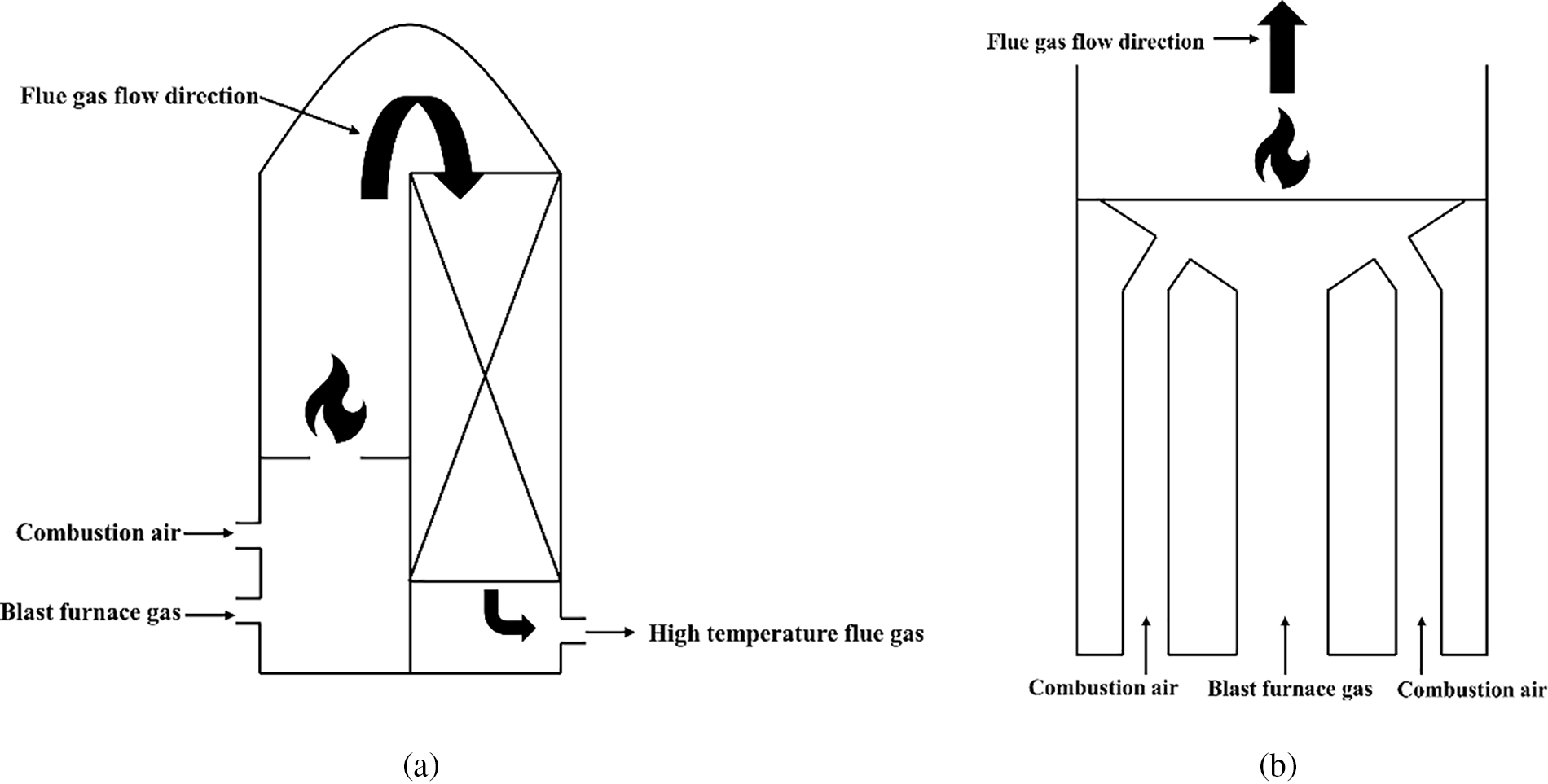
Figure 1: (a) Schematic diagram of hot blast stove combustion; (b) Rectangular burner cross section
There are many factors that affect the hot blast temperature, such as the structure of the hot blast stove, the adjustment of air and fuel ratio, the temperature of the air or the gas, and so on [11–14]. In the process of combustion and air supply, complex physical phenomena and chemical reactions occur in the hot blast stove, such as heat and mass transfer, convection and radiation, and combustion reactions. In addition, the structure of the burner can directly affect the distribution of the temperature field and flow field in the combustion chamber [15–19]. Due to the continuous development of computer technology, the numerical studies on hot blast stove simulation have become a frequently used and effective research method [20–22]. The simulation of specific parts of the hot blast stove can effectively determine the direction to solve the problem and improve the efficiency of the solution [23–25]. At present, most of the research on hot blast stoves focuses on the combustion air nozzle of the burner, the combustion situation of the combustion chamber, and the influence of the gas preheating temperature on the combustion effect. For instance, Hu et al. [26] performed a numerical simulation of the flow and mixing of air and gas inside the internal combustion hot blast stove, and obtained the temperature distributions, combustion conditions and flame shape of the gas after mixing. Qi et al. [27] proposed a new type of hot blast stove structure to solve the problems of uneven pressure, eccentric eddy current and uneven temperature distribution in traditional hot blast stoves, and simulated the structure. Chen et al. [28] used numerical simulation for internal combustion hot blast stoves to find the combustion efficiency and the vault temperature under different operating conditions, and obtain a mathematical model that correctly expresses the relationship between air preheating temperature, gas flow, air-fuel ratio, and gas composition, combustion efficiency and vault temperature.
In the past, the research work mainly focused on the improvement of the preheating temperature of blast furnace gas, the number of air nozzles and the combustion of the combustion chamber. However, the research and improvement of the blast furnace gas channel in the rectangular burner are rarely involved, and the form of the blast furnace gas channel will directly affect the combustion mixing in the combustion chamber. By studying and optimizing the structure of the rectangular burner in the hot blast stove, it will have a great effect on improving the combustion efficiency. This paper firstly establishes the mathematical model of the hot blast stove combustion, the distribution of the recirculation zone, the combustion outlet temperature distribution and the CO concentration distribution are obtained. A burner with a new structure is proposed to change the flow direction of blast furnace gas, it is more fully mixed with combustion air, improving the combustion efficiency at the corner of the eye, changing the distribution of the reflow area to reduce the impact of vibration on the structure of the hot blast stove.
The combustion process in the combustion chamber of an internal combustion hot blast stove is a physical and chemical process involving the interaction of gas flow, heat and mass transfer, and complex chemical reaction. The combustion process is described by continuity equations, momentum equations, energy equations, and component conservation equations. Therefore, based on a commercial computational fluid dynamics software ANSYS FLUENT, an internal combustion hot blast stove combustion model was established.
The fluid flow adopts the turbulence model, and the control equation adopts the standard
In the formula:
In the simulation of the radiation heat transfer between the inner surface of the hot blast stove and the combustion gas, the discrete ordinates (DO) radiation model is adopted in this paper. For the gray body medium, considering its absorption, emission, and scattering lines, the radiation transfer equation along direction
In the formula:
For the combustion of blast furnace gas in the combustion chamber of an internal combustion hot blast stove, the gas and air in the inlet channel enter separately, so the combustion model is a typical non-premixed model vs. a non-premixed reaction model. For non-premixed combustion models. In this paper, the probability density function (PDF) model is used to calculate the situation of the combustion chamber.
Fluent’s response to turbulence is mainly to predict the time average of the pulsation. When applying PDF in the non-premixed reaction model, Fluent uses the PDF model to correlate the time average value with the instantaneous value of the turbulent chemical reaction. PDF can be seen as a function of time flowing in state
In the formula:
3 Calculation Method and Conditions
3.1 Model Building and Mesh Generation
The three-dimensional model is shown in Fig. 2. The physical model of the internal combustion hot blast stove is composed of a rectangular burner and a combustion chamber, and the rectangular combustion chamber is composed of a combustion air channel and a blast furnace gas channel. The height of the combustion chamber is 22.616 m, the diameter of the inlet of the blast furnace gas channel is 1.8 m, and the length is 2.6 m, and the inlet of the combustion-supporting air channel is 2.38 m in diameter and 2.43 m in length. There are a total of 56 combustion-supporting air nozzles of the rectangular burner, and the angle between the nozzles and the horizontal plane is 54°. After the combustion-supporting air is ejected from the nozzle, the high-temperature combustion-supporting air sprayed from the nozzle quickly mixes and reacts with the blast furnace gas in the middle pipe, enters the combustion chamber and burns and produces high-temperature flue gas.
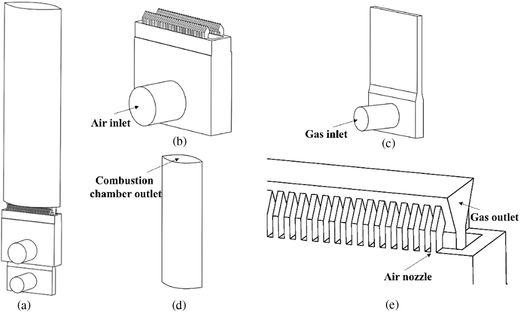
Figure 2: (a) Internal combustion hot blast stove model; (b) Combustion air channel; (c) Blast furnace gas channel; (d) Combustion chamber; (e) Burner outlet
Fluent Meshing is used to mesh the physical model of the combustion chamber in this paper. The grid form is a polyhedral grid, and the air and gas nozzles are processed by grid encryption. The number of grids in the calculation area of the burners of the two structures is 2.26 million. The grid structure is shown in Fig. 3. The maximum inclination of the grid is less than 0.35, which ensures that the grid has good calculation accuracy.
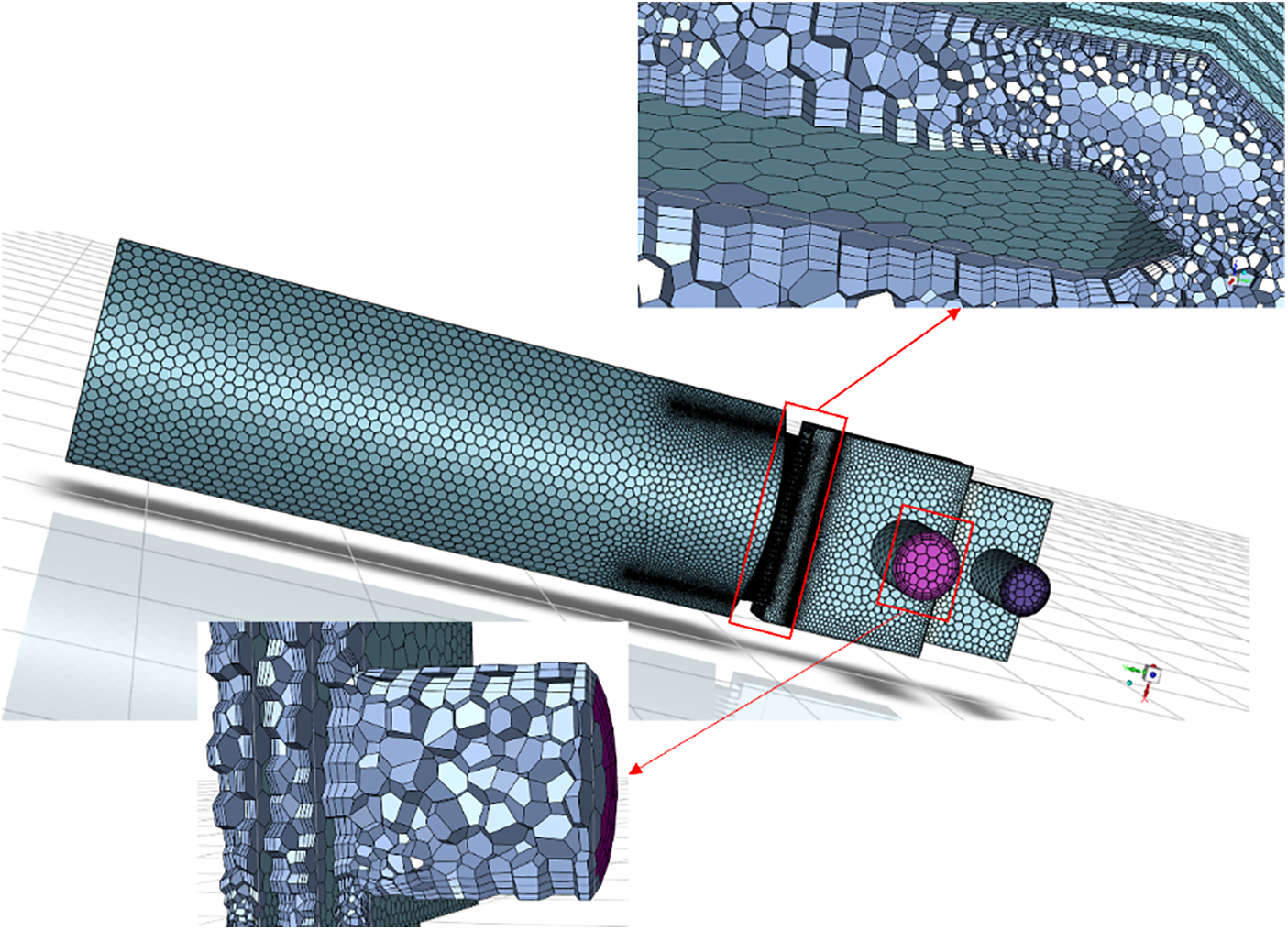
Figure 3: Hot blast stove polyhedral meshing
3.2 Grid Independence Verification
Before the numerical simulation of the internal combustion hot blast stove, first check whether the simulated calculation results change with the change of the number of grids, and eliminate the influence of the number of grids on the calculation results. In this paper, four sets of data are used to verify the grid independence, calculation results are shown in Fig. 4.
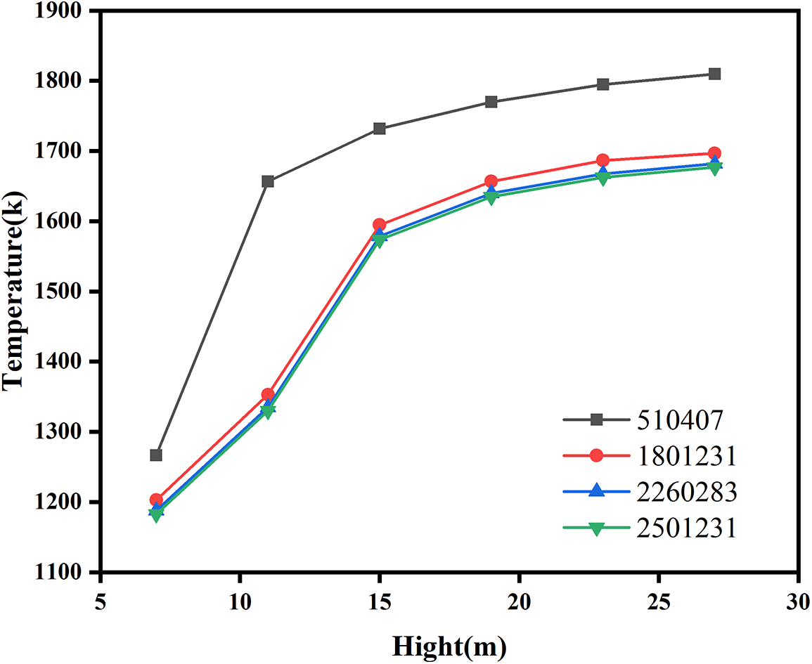
Figure 4: Results of temperature change in combustion chamber under different number of grids
It can be clearly seen from Fig. 4 that the temperature change curves in the combustion chamber under the three grids with unit numbers of 1.8 million, 2.26 million and 2.5 million are relatively close. The maximum error between the results of 1.8 million and 2.26 million grids and the 2.5 million grids are 1.48% and 0.29%, respectively, and the relative error between the calculation results of the 3 sets of grid systems is less than 2%. The difference between the calculation result of 510,000 grids and the calculation result of 2.5 million grids is the largest by 24.6%. In order to improve the calculation accuracy, considering the economic efficiency of the calculation, the number of grid cells selected in the calculation results of this paper is 2.26 million.
3.3 Boundary Conditions and Basic Assumptions
(1) Inlet boundary conditions
The composition of the blast furnace gas used in the hot blast stove combustion is shown in Table 1. The relevant operating parameters of blast furnace gas and combustion air are shown in Table 2. The inlet boundary conditions of combustion air and blast furnace gas are velocity inlet boundary conditions.
(2) Export boundary conditions
The outlet boundary condition is set as the pressure outlet boundary condition, and the static pressure of the outlet boundary condition is 1.06 atm.
(3) Wall condition
The wall boundary condition is set to non-slip adiabatic wall.
(4) Basic assumptions
In order to facilitate the study of internal combustion hot blast stove combustion chamber gas flow and combustion vibration characteristics, here to make the following assumptions:
Air and gas inlet velocities and temperatures are assumed to be uniform, the fluid is an incompressible fluid, the flow is turbulent flow, the specific heat capacity of different components in gas can be considered as a function of temperature, and the viscous heat is not considered. The combustion flue gas is ash, the radiation gas is CO2 and H2O, and the gas radiation absorption coefficient is not affected by the turbulence characteristics. The wall surface is gray body and is considered as the third kind of boundary condition. The combustion process is in a stable state, and the combustion mode is namely mixed combustion, and fuel and oxygen do not coexist.
Due to the complexity of the combustion process of mixed gas, in order to simplify the calculation, the following assumptions are made when calculating the excess air coefficient:
The volume of gas is calculated according to the standard state (273 K and 105 Pa), and the volume of every 1 mol of all gases in the standard state is 22.4 L. The composition of air only considers O2 and N2, products of thermal decomposition are not taken into account in the calculation.
4.1 Original Structure Simulation
After analyzing the combustion simulation of the original hot blast stove, the distribution of the velocity field in the combustion chamber is obtained. The interface diagram of velocity vector distribution is shown in Fig. 5. It can be seen that the blast furnace gas and combustion air are burned at the bottom of the combustion chamber to form a recirculation zone. A small reflow zone is generated at the corners of the eyes at both ends of the bottom of the combustion chamber, while there is a larger reflow zone in the middle of the combustion chamber near the front and rear walls, and the reflow zones are basically symmetrically distributed.
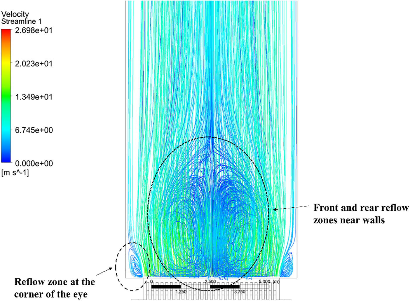
Figure 5: The velocity distribution diagram of the combustion chamber under the original structure
4.1.2 Temperature Field Analysis
The temperature distribution of the vertical section and the temperature distribution map of different heights of the combustion chamber are shown in Fig. 6. From the temperature distribution of the vertical section in Fig. 6a, it can be seen that the combustion occurs at the bottom of the combustion chamber, and the temperature becomes higher as the height of the combustion chamber increases.
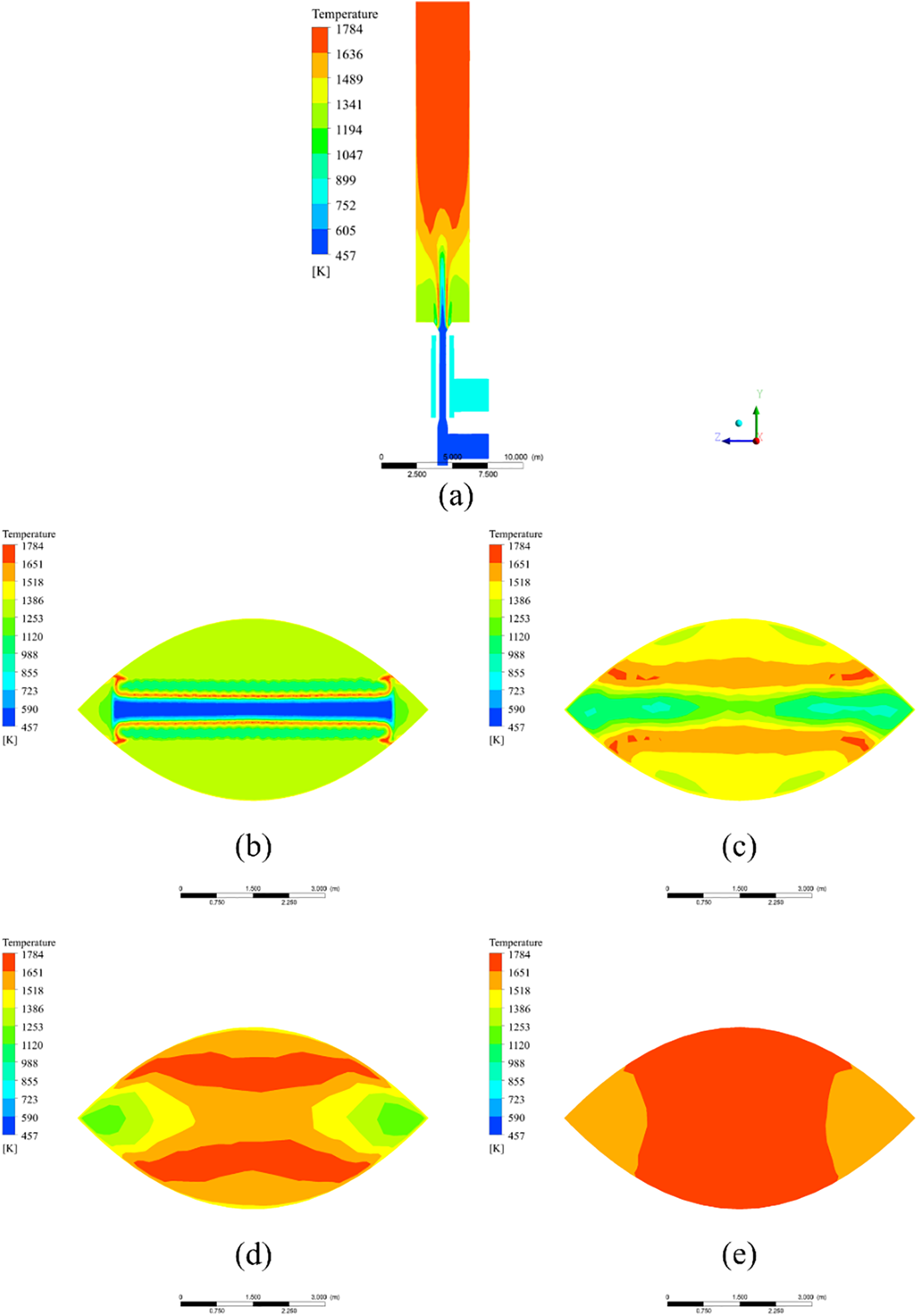
Figure 6: (a) Vertical section temperature map; (b) Height is 6.8 m; (c) Height is 11.8 m; (d) Height is 14.3 m; (e) Height is 29.3 m
Fig. 6b shows that at the bottom of the combustion chamber, the combustion-supporting air and the blast furnace gas have just contacted each other and have not yet started to react, and the combustion chamber inlet temperature is relatively low.
Fig. 6c shows that the combustion-supporting air and the blast furnace gas have started to react, and the temperature of the middle part has begun to rise, and the heat has begun to be emitted to both ends.
It can be seen from Fig. 6d–e that the temperature gradually increases with the height, but the temperature at the corner of the eye rises relatively slowly. From the temperature distribution at the outlet, it can be seen that the high temperature is mainly distributed in the middle part.
4.1.3 CO Concentration Field Analysis
The CO average volume fraction distribution map at different heights of the combustion chamber and the CO average volume fraction distribution of the vertical section are shown in Fig. 7.
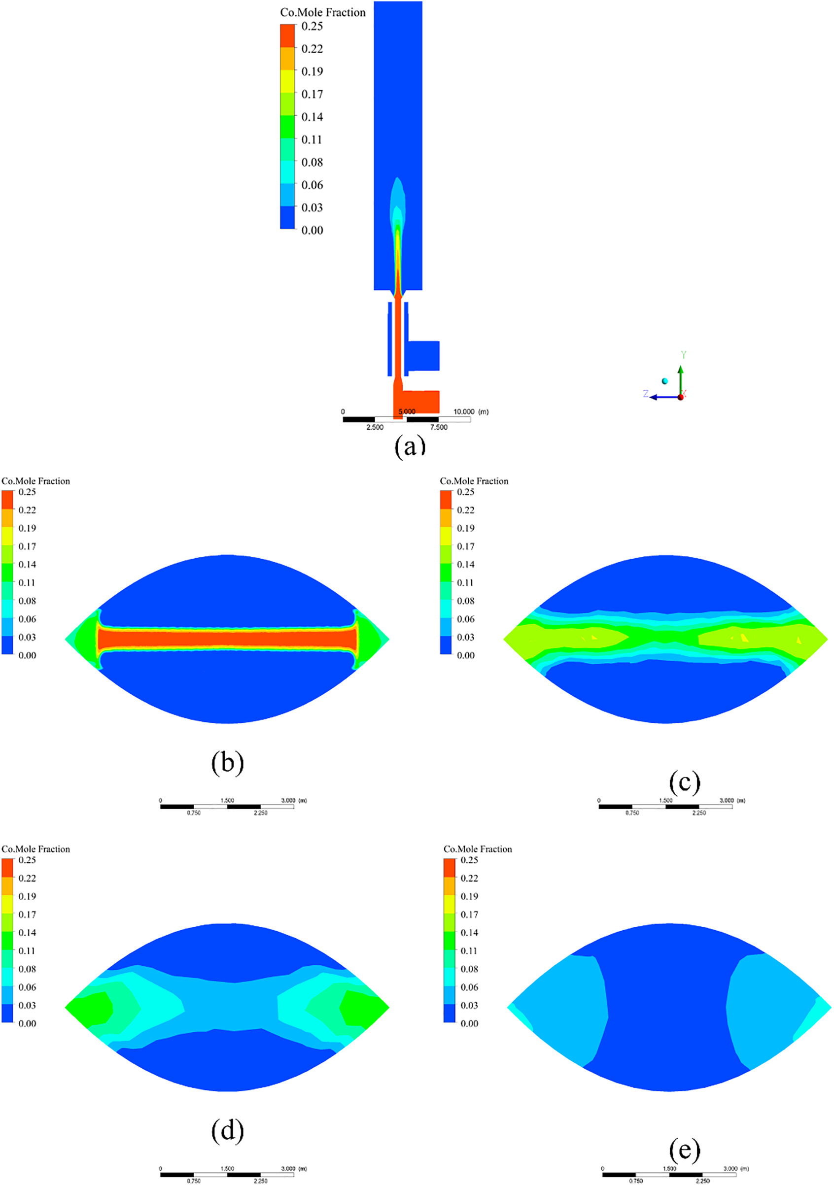
Figure 7: (a) CO Volume fraction diagram in vertical section; (b) Height is 6.8 m; (c) Height is 11.8 m; (d) Height is 14.3 m; (e) Height is 29.3 m
From the average volume fraction distribution of CO in the vertical section of Fig. 7a, the blast furnace gas reacts with combustion-supporting air after entering the combustion chamber, consuming a large amount of CO in the blast furnace gas, with the increasing height, the concentration of CO is also decreasing, which is consistent with the actual law of the internal combustion hot blast stove.
It can be seen from Fig. 7b that most of the CO at the bottom of the combustion chamber is distributed at the middle inlet, it mainly comes from blast furnace gas and spreads to the corners of the eyes at both ends.
Fig. 7c shows that the combustion reaction of blast furnace gas and combustion-supporting air in the middle part consumes a large amount of CO, so that the average volume of CO in the middle part begins to decrease, at the same time, CO began to diffuse around, and the average volume fraction of CO at the corner of the eye increased.
Fig. 7d–e shows that as the height of the combustion chamber continues to rise, the average volume fraction of CO continues to decrease, from the perspective of the outlet section, there is still a part of CO distributed in the corners of the eyes at both ends of the outlet.
4.1.4 Simulation Model Verification
In order to verify whether the calculation model is accurate and high similarity to the actual situation, the temperature and CO concentration were verified. The actual dome temperature of the combustion chamber is 1651 K, the simulated temperature is 1686 K. The simulation model results are similar to the measured results. Compared with the CO concentration at the outlet of the actual combustion chamber, it can be found that the simulated CO concentration is 7082 ppm, and the actual CO concentration is about 7243 ppm, which is close to the CO concentration generated by the hot blast stove under actual working conditions, and can be used to guide actual working conditions.
According to the previous simulation of the original structure of the internal combustion hot blast stove, it can be obtained that the mixture of combustion air and blast furnace gas is not sufficient. This corresponds to the need for a higher air-fuel ratio in the actual production process of the steel plant to reach the required temperature. It is related to the size of the combustion chamber of the internal combustion hot blast stove and the structure of the rectangular burner. However, it can be seen from the temperature and CO concentration distribution diagram in the combustion chamber that after the blast furnace gas enters the combustion chamber, it will easily flow to the corners of the two ends of the combustion chamber, resulting in the blast furnace gas at the corners of the two ends cannot be fully mixed and combusted with the combustion-supporting air, So it can be clearly seen in the previous temperature distribution that the temperature at both ends of the eye is lower than the temperature in the middle, and the CO distribution diagram shows that CO is mainly distributed at the corners of the eyes at both ends. In response to this problem, it is proposed to improve the structure of the internal combustion hot blast stove to improve the mixed combustion between blast furnace gas and combustion air, and reduce the flow of blast furnace gas to the corners of the two ends of the combustion chamber.
Adding baffles can change the direction of gas flow, which is widely used in the steel industry. In order to optimize the structure of the existing furnace body, an improved internal combustion hot blast stove is proposed. The improved part is shown in Fig. 8. In the part where the blast furnace gas channel and the combustion chamber are in contact with each other, an inclined baffle is added to offset the flow direction of the blast furnace gas into the combustion chamber, so that the blast furnace gas flows to the middle part and the combustion-supporting air sprayed from the nozzle is fully mixed and combusted, the tilt angle is 45°, 60°, 75° three sets of experiments for testing. The hot blast stove design is consistent with the newly designed. The performance of the improved hot blast stove is studied by establishing the relevant mathematical model and setting the boundary conditions.
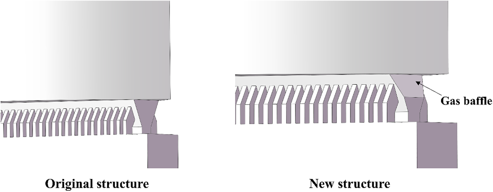
Figure 8: Gas channel improvements
4.2.2 Comparison of CO Concentration at Different Angles of Inclination
Numerical simulation of three gas baffles with different positions. The purpose of adding the gas baffle is to reduce the CO in the outlet flue gas, so the volume fraction of the outlet CO becomes the basis for judging the effect of the gas baffle. It can be seen from Fig. 9 that as the tilt angle continues to increase, the concentration of CO in the outlet flue gas first rises and then falls, the volume fraction of CO at the outlet with an inclination angle of 60° is the least. Therefore, a hot blast stove with a gas baffle with an inclination angle of 60° is selected for subsequent specific analysis of the velocity field, temperature field and concentration field.
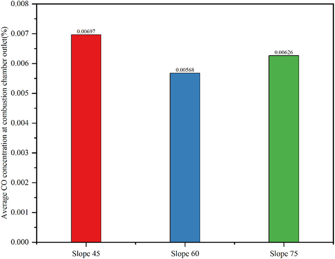
Figure 9: The average CO extraction score at the outlet of the gas baffle at different inclination angles
4.2.3 Improved Speed Field Analysis
The combustion situation in the combustion chamber of the improved hot blast furnace is numerically simulated, and the distribution of the velocity field in the combustion chamber is analyzed. The interface diagram of the velocity vector distribution is shown in Fig. 10. It can be seen that compared with the original structure, the scope of the reflow zone in the middle of the bottom of the combustion chamber near the front and rear walls has decreased, but the scope of the low-speed reflow zone at the corners of the eyes at both ends has increased.
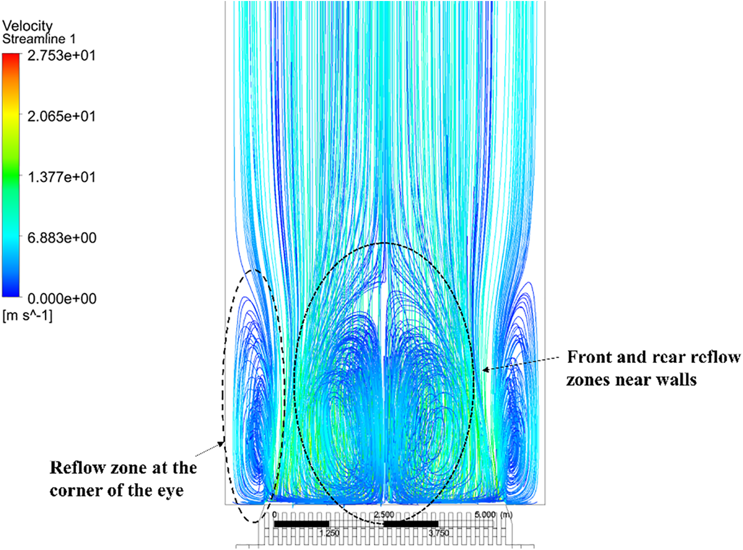
Figure 10: Speed distribution diagram of the combustion chamber under the new structure
4.2.4 Improved Temperature Field Analysis
It can be seen from the distribution of the average volume fraction of CO in the vertical section of Fig. 11a that the height of the combustion flame in the improved temperature field is significantly improved. The combustion height of the flame can represent the degree of mixed combustion between the blast furnace gas and the combustion air, the increase in the flame length means that the combustion effect becomes better.
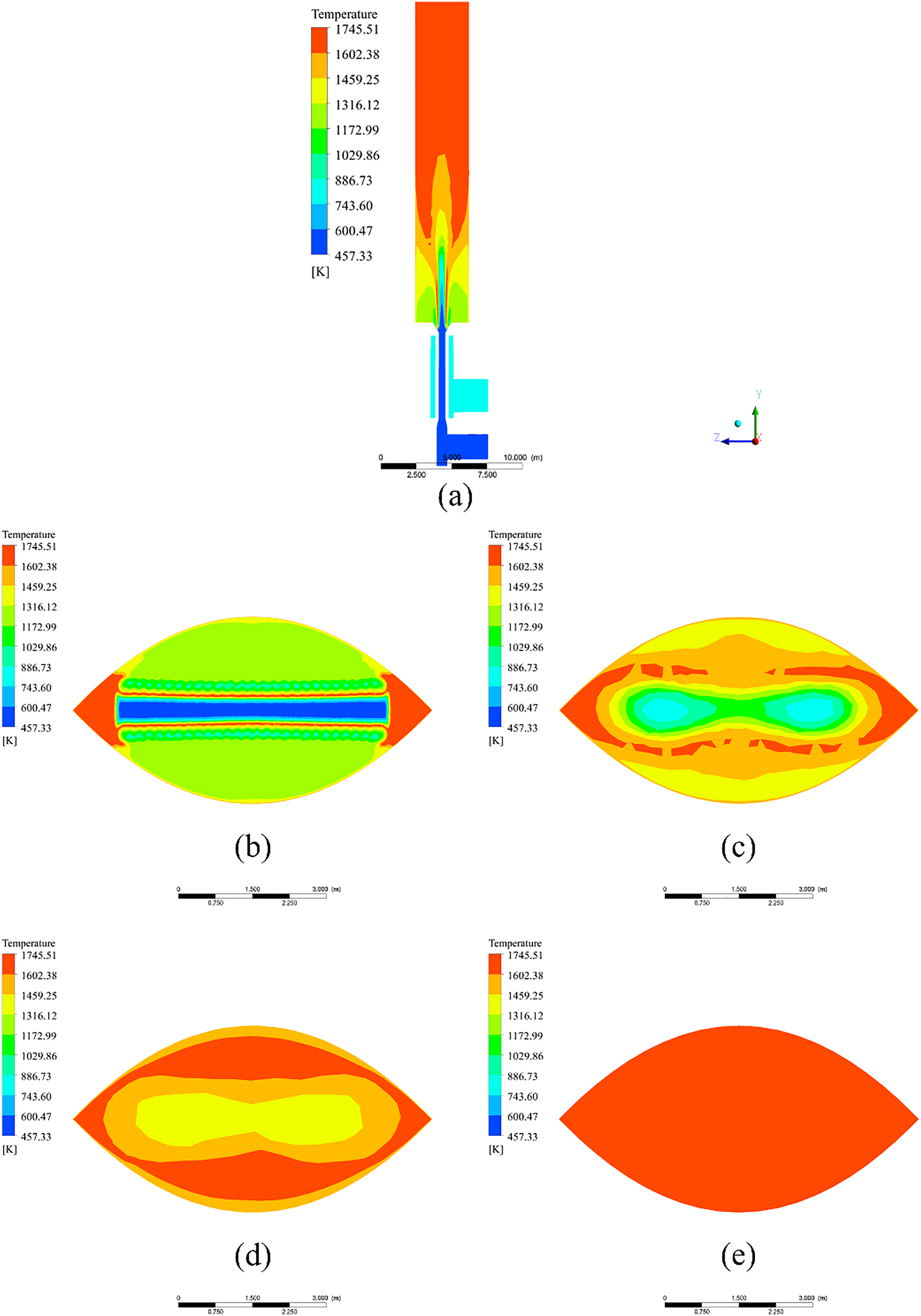
Figure 11: (a) Vertical section temperature map; (b) Height is 6.8 m; (c) Height is 11.8 m; (d) Height is 14.3 m; (e) Height is 29.3 m
From Fig. 11b, it can be seen that the temperature at the corner of the eye has increased significantly, indicating that the blast furnace gas in the corner of the eye is fully burned, resulting in a rise in temperature. The reason is that under the action of the gas baffle, the blast furnace gas is biased to the central part, so that part of the blast furnace gas and the combustion-supporting air are fully contacted and reacted, when the blast furnace gas flows to the corner of the eye, it has already reacted with the combustion-supporting air to release heat, so as to achieve the expected purpose of adding the gas baffle.
From Fig. 11c, it can be seen that compared with when the gas baffle is not added, the place where the combustion occurs is not only around the central part, but also at the corners of the eyes at both ends. It is proved that the blast furnace gas has more contact parts with the combustion-supporting air, and the combustion mixture is more uniform.
From Fig. 11d–e, it can be seen that with the increase of height, the temperature is also gradually increasing. Compared with the original structure, the residual problem of blast furnace gas at the corner of the eye is fully improved. The blast furnace gas at the corner of the eye also fully reacts with the combustion-supporting air to release heat. It can be seen from the outlet interface that the temperature distribution becomes more uniform and the temperature increases, which is conducive to the hot air entering the heat storage chamber and reducing damage to the vault, the structural stability of the internal combustion hot blast stove is obviously improved.
From Fig. 12, it can be seen that after the new structure is used, the change of temperature does not change much, which is similar to the change of the original model. As the height increases, the temperature also increases, and the temperature at the bottom of the combustion chamber is greater than that at the bottom of the original structure, which corresponds to the variation law of CO concentration, the new structure after adding the gas baffle makes the blast furnace gas biased to the middle part, so that the initial combustion-supporting air and the blast furnace gas can fully react, reducing the concentration of CO makes the reaction emit more heat, so the initial temperature is significantly increased. For the hot blast stove with improved structure, the temperature has been improved to a certain extent, the average temperature of the combustion bottom rises from 1183 to 1237 K, and the average temperature of the combustion chamber outlet rises from 1686 to 1693 K. It can be seen that the degree of combustion has been improved after using the new structure, which corresponds to the reduction of the outlet CO concentration.
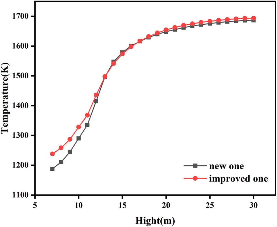
Figure 12: The temperature curve along the height of the combustion chamber after the improvement
4.2.5 Improved CO Concentration Field Analysis
Fig. 13a shows that the average volume fraction distribution of CO in the vertical section. Compared with the original structure, the average volume fraction distribution of CO has changed.
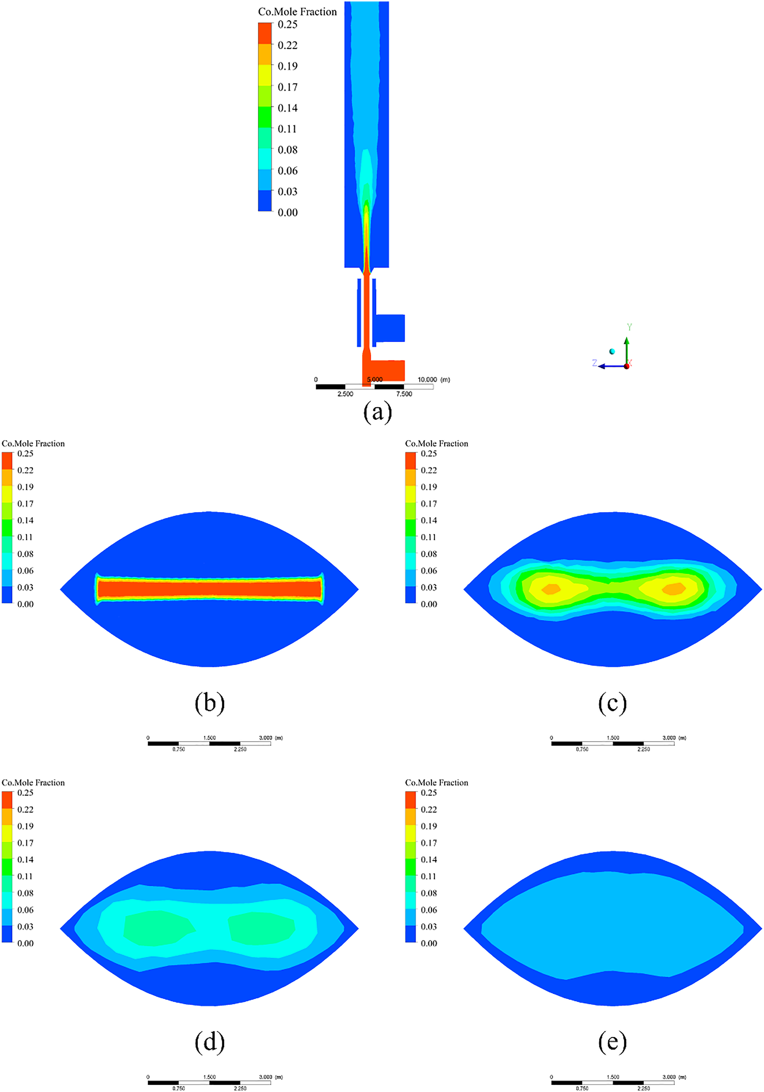
Figure 13: (a) CO Volume fraction diagram in vertical section; (b) Height is 6.8 m; (c) Height is 11.8 m; (d) Height is 14.3 m; (e) Height is 29.3 m
From Fig. 13b, it can be seen that the average volume fraction of CO at the corners of the eyes at both ends has decreased significantly, indicating that the contact range of blast furnace gas and combustion-supporting air has become wider.
From Fig. 13c, it can be seen that the CO concentration at the corners of the eyes at both ends has decreased significantly, which proves that the gas baffle is the reaction of the blast furnace gas at the corners of the eyes and the combustion-supporting air, which reduces the flow of blast furnace gas to the corners of the two ends.
From Fig. 13d–e, it can be seen that the average volume fraction of CO gradually decreases. Compared with the previous structure, the problem of insufficient combustion at the corners of the eyes at both ends has been effectively improved. The average volume fraction of CO in the outlet section decreases to a certain extent, and the distribution of CO is more uniform, which improves the stable operation of the hot blast stove and reduces the potential safety hazard.
It can be seen from Fig. 14 that the CO variation law using the new structure has a new change. Before 11 m, the CO rises with the height of the combustion chamber, after 11 m, it starts to decrease rapidly like the original structure, and finally the average volume fraction of CO tends to remain unchanged. Initially, in contrast to the original structure, the CO concentration at the bottom of the combustion chamber is significantly reduced. It can be seen that after the improvement, the CO concentration of the hot blast stove decreased significantly. The CO concentration at the bottom of the combustion chamber decreased from 41,362 to 31,280 ppm. The reason is that the gas baffle makes the combustion-supporting air and blast furnace gas more evenly mixed, so the reaction consumes more CO and reduces the CO content. As the height increases, the concentration of CO increases. Because a large amount of CO is consumed in the initial reaction, the peak value of the increase is obviously lower than that of the original structure. As the speed of combustion-supporting air and blast furnace gas reaches a stable level, and the surrounding temperature also rises to a certain level, the average volume fraction of CO decreases with the increase of height, and finally gradually stabilized. Overall, the CO concentration after the improvement was greatly reduced.
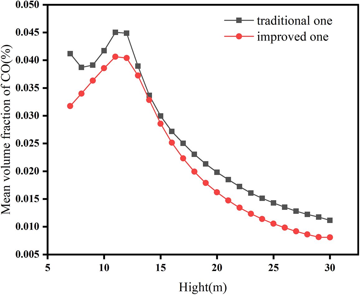
Figure 14: The average CO volume percentage along the height of the combustion chamber after the improvement
This paper takes Shou gang’s No. 3 blast furnace hot blast stove as the research object, establishes an internal combustion hot blast stove three-dimensional model, analyzes the change law of the concentration field and temperature field in the combustion process of the hot blast stove. The following conclusions can be drawn:
(1) It can be clearly seen from the simulation of the internal combustion hot blast stove that the recirculation area is mainly concentrated in the center part of the bottom of the combustion chamber, and there are fewer recirculation areas at the corners of the eyes at both ends of the bottom, causing the high temperature area at the outlet to be concentrated in the middle part, and the CO concentration at the corners of the eyes at both ends is higher.
(2) After using the gas baffle, the blast furnace gas under the new structure reduces the flow to the corners of both ends of the combustion chamber, changing the distribution of the return zone. The scope of the recirculation zone in the middle part is reduced, and the scope of the recirculation zone at the corners of the eyes is enlarged, which improves the combustion situation at the corners of the eyes at both ends, reduces the CO concentration at the outlet, and the uniformity of temperature distribution is improved. When the gas baffle is placed at an inclination angle of 60°, the combustion chamber outlet section average temperature rises from 1686 to 1693 K, the outlet flue gas average volume fraction of CO decreases the most, and the average volume fraction of CO decreases from 0.00708% to 0.00568%, which could reduce the CO content by about 20%.
Acknowledgement: The authors express their gratitude to their affiliated universities.
Funding Statement: The authors received no specific funding for this study.
Author Contributions: The authors confirm contribution to the paper as follows: study conception and design, data collection, analysis and interpretation of results, and draft manuscript preparation: Ruibin Wang, Fuyong Su, Shuo Huang, Shengyong Ma. All authors reviewed the results and approved the final version of the manuscript.
Availability of Data and Materials: Data available on request from the authors.
Ethics Approval: Not applicable.
Conflicts of Interest: The authors declare no conflicts of interest to report regarding the present study.
References
1. Rieger J, Weiss C, Rummer B. Modelling and control of pollutant formation in blast stoves. J Clean Prod. 2015;88(6):254–61. doi:10.1016/j.jclepro.2014.07.028. [Google Scholar] [CrossRef]
2. Hu C, Chen L, Zhang C, Qi Y, Yin R. Emission mitigation of CO2 in steel industry: current status and future scenarios. J Iron Steel Res Int. 2006;13(6):38–42. doi:10.1016/S1006-706X(06)60107-6. [Google Scholar] [CrossRef]
3. Tanmay D. Design and computational fluid dynamics analysis of a novel compact mixing chamber in blast furnace ironmaking. J Thermal Sci Eng Appl. 2022;14(2):1–22. doi:10.1115/1.4051242. [Google Scholar] [CrossRef]
4. Wang K, Zhang J, Zhou H, Ni J, Hu Y. Numerical study of natural gas and pulverized coal co-injection into an ironmaking blast furnace. Appl Therm Eng. 2023;230:120817. doi:10.1016/j.applthermaleng.2023.120817. [Google Scholar] [CrossRef]
5. Chen L, Yang B, Shen X, Xie Z, Sun F. Thermodynamic optimization opportunities for the recovery and utilization of residual energy and heat in China’s iron and steel industry: a case study. Appl Therm Eng. 2015;86(10):151–60. doi:10.1016/j.applthermaleng.2015.04.026. [Google Scholar] [CrossRef]
6. Tan X, Li H, Guo J, Gu B, Zeng Y. Energy-saving and emission-reduction technology selection and CO2 emission reduction potential of China’s iron and steel industry under energy substitution policy. J Clean Prod. 2019;222(44):823–34. doi:10.1016/j.jclepro.2019.03.133. [Google Scholar] [CrossRef]
7. He K, Wang L. A review of energy use and energy-efficient technologies for the iron and steel industry. Renew Sust Energ Rev. 2017;70(1):1022–39. doi:10.1016/j.rser.2016.12.007. [Google Scholar] [CrossRef]
8. Arapov AA, Sal’nikov AV, Fedoseev YA. Improving the performance of hot-blast stoves at EVRAZ ZSMK. Metallurgist. 2019;63:545–8. doi:10.1007/s11015-019-00856-1. [Google Scholar] [CrossRef]
9. Andreev A, Sinitsyn N. A model of the dynamics of heat exchange and control of the cooling process in a moving dense layer of hot blast furnace slag. Metallurgist. 2022;65(11–12):1361–8. doi:10.1007/S11015-022-01283-5. [Google Scholar] [CrossRef]
10. Chen C, Cheng S, Guo X. Hazard control of NOx in hot stove. J Iron Steel Res Int. 2014;21(3):306–11. doi:10.1016/S1006-706X(14)60047-9. [Google Scholar] [CrossRef]
11. Hooey PL, Bodén A, Wang C, Grip C, Jansson B. Design and application of a spreadsheet-based model of the blast furnace factory. ISIJ Int. 2010;50(7):924–30. doi:10.2355/isijinternational.50.924. [Google Scholar] [CrossRef]
12. Moon J, Kim S, Sasaki Y. Effect of preheated top gas and air on blast furnace top gas combustion. ISIJ Int. 2014;54(1):63–71. doi:10.2355/isijinternational.54.63. [Google Scholar] [CrossRef]
13. Siviryuk LV, Gramotnik VI, Bezrukov NA, Prorovskaya VO. Estimation of the state of metal of blast-furnace jackets and hot-blast stove casings by a nondestructive testing method. Russ J Nondestruct. 2003;39(9):678–82. doi:10.1023/B:RUNT.0000019719.92608.15. [Google Scholar] [CrossRef]
14. Guo H, Yan B, Zhang J, Liu F, Pei Y. Optimization of the number of burner nozzles in a hot blast stove by the way of simulation. JOM. 2014;66(7):1241–52. doi:10.1007/s11837-014-1022-z. [Google Scholar] [CrossRef]
15. Xiao R, Zhang J, Jiao S. Influence of guide vane angle of circulating hot blast stove sleeve on temperature field and flow field. J Phys: Conf Ser. 2021;1983(1):012037. doi:10.1088/1742-6596/1983/1/012037. [Google Scholar] [CrossRef]
16. Zhang Q, Tang Y. Numerical study of the influence of regenerator structure on the performance of hot blast stoves. Metals. 2024;14(8):869. doi:10.3390/MET14080869. [Google Scholar] [CrossRef]
17. Park D, Guo F, Kim N. Stress corrosion cracking analysis of a hot blast stove shell with an internal combustion chamber. Appl Sci. 2023;13(22):12297. doi:10.3390/app132212297. [Google Scholar] [CrossRef]
18. Zhang F, Mao Q, Mei C, Li X, Hu Z. Dome combustion hot blast stove for huge blast furnace. J Iron Steel Res Int. 2012;19(9):1–7. doi:10.1016/S1006-706X(13)60001-1. [Google Scholar] [CrossRef]
19. Kimura Y, Takatani K, Otsu N. Three-dimensional mathematical modeling and designing of hot stove. ISIJ Int. 2010;50(7):1040–7. doi:10.2355/isijinternational.50.1040. [Google Scholar] [CrossRef]
20. Zhang Q, Chen L, Ma X, Zhao C. Numerical study of combustion and air supply characteristics and structural optimization of top combustion hot blast stoves: ironmaking. ISIJ Int. 2021;61(1):62–70. doi:10.2355/isijinternational.ISIJINT-2020-119. [Google Scholar] [CrossRef]
21. Zhang Q, Chen L, Zhao C. Numerical simulation of combustion and air supply process and optimal design of traditional top combustion hot blast stoves. J Iron Steel Res Int. 2020;92(2):452. doi:10.1002/srin.202000311. [Google Scholar] [CrossRef]
22. Zhao M, Pan Y, Meng F, Ma P, Jia L, Ma G, et al. CFD numerical simulation of operation optimization for energy saving during combustion period of kalugin top combustion hot blast stove. Trans Indian Inst Met. 2023;76(7):1967–76. doi:10.1007/s12666-023-02903-7. [Google Scholar] [CrossRef]
23. Pitsch H. Large-eddy simulation of turbulent combustion. Annu Rev Fluid Mech. 2006;38(1):453–82. doi:10.1146/annurev.fluid.38.050304.092133. [Google Scholar] [CrossRef]
24. Santos DGR, Lecanu M, Ducruix S, Gicquel O, Iacona E, Veynante D. Coupled large eddy simulations of turbulent combustion and radiative heat transfer. Combust Flame. 2008;152(3):387–400. doi:10.1016/j.combustflame.2007.10.004. [Google Scholar] [CrossRef]
25. Wu H, Ihme M. Compliance of combustion models for turbulent reacting flow simulations. Fuel. 2016;186(3):853–63. doi:10.1016/j.fuel.2016.07.074. [Google Scholar] [CrossRef]
26. Hu Z, Cheng S, Zhang F. Transport phenomenon of Hoogovens internal hot blast stoves. Chin J Eng. 2010;32(8):1053–9. [Google Scholar]
27. Qi F, Liu Z, Yao C, Li B. Numerical study and structural optimization of a top combustion hot blast stove. Adv Mech Eng. 2015;7(2):709675. doi:10.1155/2014/709675. [Google Scholar] [CrossRef]
28. Chen S, Guo H, Zhang J, Yang T. Combustion model of a hot blast stove based on numerical simulation. Chin J Eng. 2011;33(5):627–31. [Google Scholar]
Cite This Article
 Copyright © 2025 The Author(s). Published by Tech Science Press.
This work is licensed under a Creative Commons Attribution 4.0 International License , which permits unrestricted use, distribution, and reproduction in any medium, provided the original work is properly cited.
 Downloads
 Citation Tools