
 Submit a Paper
 Propose a Special lssue
 Open Access
ARTICLE
Experimental Study on a Hybrid Battery Thermal Management System Combining Oscillating Heat Pipe and Liquid Cooling
1 School of Automotive Engineering, Jiangxi Polytechnic University, Jiujiang, 332000, China
2 Faculty of Mechanical and Automotive Engineering Technology, Universiti Malaysia Pahang Al-Sultan Abdul-lah, Pekan, 26600, Malaysia
3 Centre for Research in Advanced Fluid & Processes, Universiti Malaysia Pahang Al-Sultan Abdul-lah, Pekan, 26600, Malaysia
4 Institute of Sustainable and Renewable Energy (ISuRE), Universiti Malaysia Sarawak (UNIMAS), Kota Samarahan, 94300, Malaysia
* Corresponding Authors: Hongkun Lu. Email: ; M. M. Noor. Email:
(This article belongs to the Special Issue: Heat and Mass Transfer in Energy Equipment)
Frontiers in Heat and Mass Transfer 2025, 23(1), 299-324. https://doi.org/10.32604/fhmt.2024.059871
Received 18 October 2024; Accepted 29 November 2024; Issue published 26 February 2025
 View Full Text
 Download PDF
Abstract
To improve the thermal performance and temperature uniformity of battery pack, this paper presents a novel battery thermal management system (BTMS) that integrates oscillating heat pipe (OHP) technology with liquid cooling. The primary innovation of the new hybrid BTMS lies in the use of an OHP with vertically arranged evaporator and condenser, enabling dual heat transfer pathways through liquid cooling plate and OHP. This study experimentally investigates the performance characteristics of the ⊥-shaped OHP and hybrid BTMS. Results show that lower filling ratios significantly enhance the OHP’s startup performance but reduce operational stability, with optimal performance achieved at a 26.1% filling ratio. Acetone, as a single working fluid, exhibited superior heat transfer performance under low-load conditions compared to mixed fluids, while the acetone/ethanol mixture, forming a non-azeotropic solution, minimized temperature fluctuations. At 100 W, the ⊥-shaped OHP with a horizontally arranged evaporator demonstrated better heat transfer performance than 2D-OHP designs. Compared to a liquid BTMS using water coolant at 280 W, the hybrid BTMS reduced the equivalent thermal resistance (RBTMS) and maximum temperature difference (ΔTmax) by 8.06% and 19.1%, respectively. When graphene nanofluid was used as the coolant in hybrid BTMS, the battery pack’s average temperature (Tb) dropped from 52.2°C to 47.9°C, with RBTMS and ΔTmax decreasing by 20.1% and 32.7%, respectively. These findings underscore the hybrid BTMS’s suitability for high heat load applications, offering a promising solution for electric vehicle thermal management.Keywords
Nomenclature
| I | input current (A) |
| Q | heating power input (W) |
| QOHP | heat load transferred via OHP (W) |
| R | thermal resistance (°C/W) |
| T | temperature (°C) |
| t | time (s) |
| U | input voltage (V) |
| FR | filling ratio |
| wt% | weight percentage |
| temperature difference (°C) | |
| time difference (s) | |
| Tmax | maximum temperature (°C) |
| Tb | the average surface temperature of the batteries (°C) |
| σT | temperature standard deviation (°C) |
| RBTMS | equivalent thermal resistance of BTMS (°C/W) |
| FR | filling ratio (%) |
| con | condensation |
| eva | evaporation |
| max | maximum |
| 2D | two dimensional |
| 3D | three dimensional |
| BTMS | battery thermal management system |
| PCM | phase change material |
| OHP | oscillating heat pipe |
| CNT | carbon nanotube |
| Crate | the battery discharge/charge rate relative to its maximum capacity |
Lithium-ion batteries, the primary power source for electric vehicles (EVs), offer numerous performance advantages but also generate significant heat during charging and discharging cycles, leading to increased battery temperatures [1]. Excessive battery temperatures can severely degrade the performance and cycle life of lithium-ion batteries. Therefore, developing a reliable and efficient Battery Thermal Management System (BTMS) to control battery temperatures is crucial. To extend electric vehicle range, researchers worldwide are striving to maximize the volume utilization of power batteries, fitting more lithium-ion battery packs within the limited space of vehicle chassis [2]. Additionally, high power motors and fast charging technologies are increasingly adopted to enhance electric vehicle performance and user experience [3]. This results in the rapid accumulation of heat in a confined space under heavy loads, significantly raising the requirements for battery cooling technology and intensifying the challenges facing battery thermal management in vehicles [4,5].
Current battery cooling technologies include air cooling [6,7], liquid cooling [8,9], phase change material cooling [10], and heat pipe cooling [11]. Heat pipe cooling achieves efficient heat transfer through the physical processes of vaporization, condensation, and reflux within a sealed tube. Due to its high thermal conductivity, reversible heat flow, and excellent isothermal characteristics, the heat pipe cooling system has drawn considerable academic interest. However, the relatively high cost of heat pipes remains a limitation [12]. In the past few years, the oscillating heat pipe (OHP), a revolutionary heat pipe without a wick structure, has shown great promise due to its superior heat transfer performance, simple design, and low production cost [13,14]. An OHP’s interior diameter generally ranges between 1 and 4 mm, with the working fluid forming many randomly dispersed liquid and vapor plugs driven by surface tension. When the OHP’s evaporator and condenser portions are heated and cooled, respectively, the liquid-vapor plugs oscillate, transferring heat by phase change and convection [15,16].
Current research on OHP-based BTMS focuses on optimizing OHP structures [17,18], mixed working fluids [19,20], and nanofluids [21–23]. In these studies, standard 2D planar structures are commonly used for OHPs [24,25]. Many researchers have shown interest in structural innovations for OHPs. Chotmanee et al. added a check valve to the OHP, which significantly reduced both the startup temperature and startup time. In a closed-loop OHP with a check valve, when the maximum heat transfer reached 98.6 W, the simulated battery temperature dropped to 55.8°C [17]. Chi et al. modified the traditional U-shaped bend at the bottom of the OHP to a right-angle design, reducing the vertical length of the condenser section, optimizing space within the vehicle [18]. Similarly, they introduced an L-shaped OHP, characterized by a longer heating section and shorter cooling and adiabatic sections, enabling a more compact spatial arrangement of the battery and cooling system [26]. Chung et al. used a 3D-OHP to encircle two 18650 cylindrical batteries and studied its heat dissipation performance under 5 and 10 W thermal loads [27]. Cattani et al. experimented with a 3D-PHP featuring three bends, conducting air-cooling tests on a battery module composed of nine cylindrical cells, exploring the effects of airflow velocity and fin structure on the battery’s thermal performance [28].
Although current studies have demonstrated the feasibility of applying OHPs in BTMS, limitations remain. In OHP-based cooling systems, battery cells must be positioned near the OHP’s evaporator section, while the condenser section is reserved for housing cooling components. This configuration leads to low space utilization for the batteries. Additionally, heat from the battery can only be dissipated through the oscillating heat pipe, which restricts the heat transfer limit of the cooling system. Research indicates that in order to keep battery temperatures below 60°C, the heat transfer capacity of BTMSs using a single OHP generally ranges from 10 to 60 W [28], with a maximum observed value of 99.6 W [27]. However, by introducing a liquid cooling path alongside the OHP heat transfer route, a hybrid BTMS could substantially enhance cooling efficiency, meeting the thermal management needs of battery packs under higher charge-discharge rates [22,29,30]. Although extensive research has been conducted on hybrid BTMSs using flat heat pipes [31], gravity heat pipes [32], and loop heat pipes [33], studies on hybrid BTMSs incorporating OHPs remain limited.
To address these challenges, this study proposes a liquid-cooled BTMS based on a ⊥-shaped OHP. As illustrated in Fig. 1, the system features a vertical arrangement of the OHP’s evaporator and condenser sections, unlike conventional liquid cooling systems. This OHP structure is well-suited to the design characteristics of prismatic batteries, effectively addressing the issue of limited space for the OHP’s condenser section. Furthermore, the system retains the benefits of liquid cooling by allowing direct heat transfer through contact between the liquid cooling plate and the two sides of the battery cells. The liquid cooling plate incorporates an open-close design, with circular channels tailored to fit the OHP’s condenser section, facilitating efficient heat dissipation. The evaporator section of the OHP is in contact with the bottom surface of the prismatic battery via a custom aluminum heat collector plate, absorbing heat from the battery. This hybrid BTMS integrates both liquid cooling and OHP-based heat transfer without increasing the number of liquid cooling plates, thereby expanding the battery’s heat exchange area. As a result, the system effectively reduces the battery’s average temperature and enhances temperature uniformity across the battery pack.
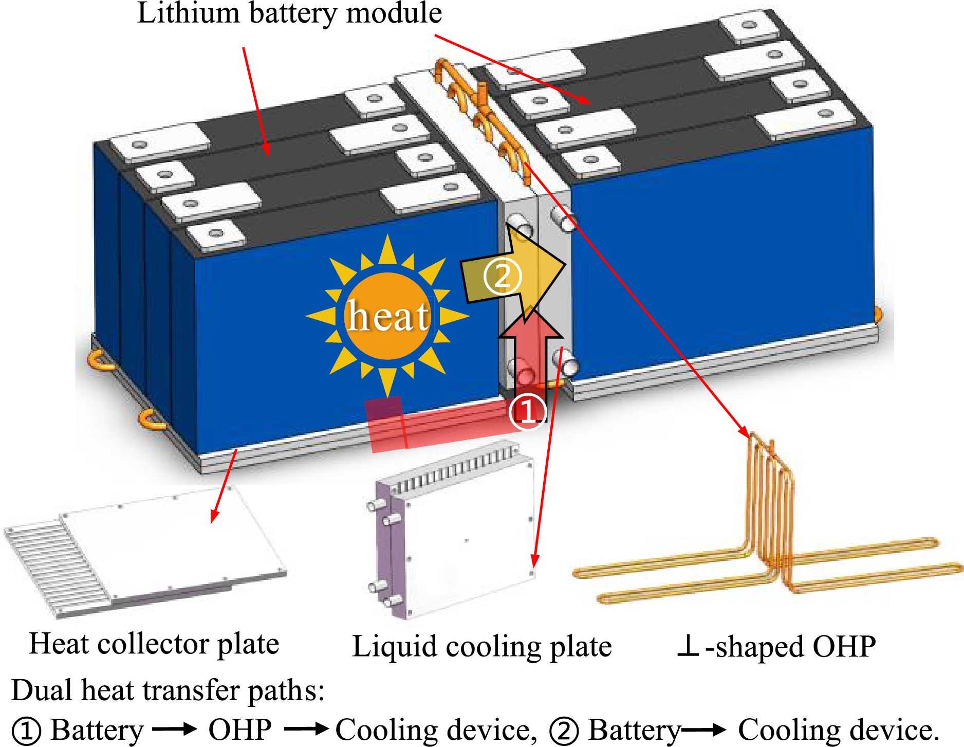
Figure 1: Schematic of the hybrid BTMS
However, this specialized OHP structure inevitably affects the gravitational distribution of the working fluid in the evaporator and condenser sections, as well as the complex multiphase flow within the tube, which in turn influences the startup and heat transfer performance of the OHP [34]. A comprehensive and systematic study of the ⊥-shaped OHP is therefore necessary. The startup and heat transfer performance of an oscillating heat pipe is significantly influenced by the physical properties of the working fluid. In battery thermal management applications, where operational temperatures are constrained, the selection of working fluids and filling ratios is critical to achieving effective temperature control [35]. Kumar et al. examined acetone, deionized water, methanol, and ethanol as working fluids in OHPs for BTMS, finding that acetone, with its low boiling point and high latent heat, performed better than other fluids for battery cooling [36]. However, there is a typical trade-off between the startup performance and dry-out resistance when using a single working fluid in OHPs. To enhance overall thermal performance, Xu et al. proposed using mixed working fluids, suggesting that an optimal blend can balance OHP characteristics [37]. Research on mixed working fluids for OHP-based BTMS is limited, with Wei and Zhou’s team being one of the few to explore this area. They found that ethanol and water, with their complementary thermal properties, allowed an ethanol-water binary mixture to achieve better temperature control at a 48 W heat load in battery cooling [19,22]. Current research on mixed fluids primarily focuses on “dry-out” resistance, but the experimental working temperatures are not always suitable for BTMS applications. Furthermore, the filling ratio is crucial to the startup and stability of the OHP, and there is ongoing debate regarding the optimal range. Generally, experiments indicate that OHPs perform best with filling ratios around 50% [35,38]. However, Chen and other researchers have suggested that the optimal filling ratio for OHP-based BTMS might be below 40% [26–28]. For example, Wei et al. found that a 30% filling ratio was optimal [19], while Zhou’s team determined an optimal range of 30%–35% when using CNTs as the working fluid [22]. Chung et al.’s study on 18650 batteries showed good performance with a filling ratio between 10% and 15% for methanol and FC-72 fluids [27]. The structure of the OHP in this study differs from previous designs, necessitating experimental verification of the optimal working fluid type and filling ratio to address the current gap in knowledge for these parameters in novel OHP structures.
In summary, we first conducted experimental research on OHPs with vertically arranged evaporator and condenser sections, analyzing the effects of different structures, working fluids, filling ratios, and heat loads on the startup and heat transfer characteristics of the OHP. Subsequently, we carried out experimental investigations on the heat transfer performance of the hybrid BTMS based on the ⊥-shaped OHP and further explored the enhancement effects of graphene nanofluids on the performance of the hybrid BTMS. The findings of this study offer both theoretical and practical insights for the structural design of OHPs and the development of OHP-based hybrid cooling systems.
2 Experimental Setup and Procedure
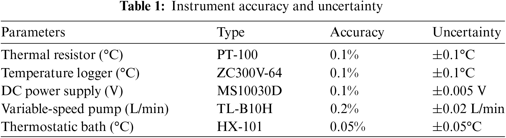
An experimental system was designed and constructed, as shown in Fig. 2. The experimental setup primarily comprises a simulated battery module (heat source), OHP, heat collector plate, liquid cooling plate, water cooling unit, and data acquisition system. To minimize heat loss from the experimental system to the surrounding environment, aluminum foil and thermal insulation cotton were used for insulation. The heat source, heat collector plate, and liquid cooling plate used in this experiment were consistent with those described in the literature [39]. To further optimize the performance of the hybrid system, a layer of thermally conductive silicone grease was applied between the contact surfaces of the simulated battery, heat collector plate, and liquid cooling plate. A constant-temperature bath (HX-101) was used to supply thermostatic cooling fluid, with the flow rate controlled by an external TL-B10H variable-speed pump. The cooling fluid in the constant-temperature bath circulates through piping connected to the liquid cooling plate, forming a closed-loop water circulation system. Temperature signals were recorded using a Zctek ZC300V-64 multi-channel data logger and PT100 thermal resistors, with a data acquisition interval of 1 s. The accuracy of the main equipment used in the experiment is shown in Table 1.
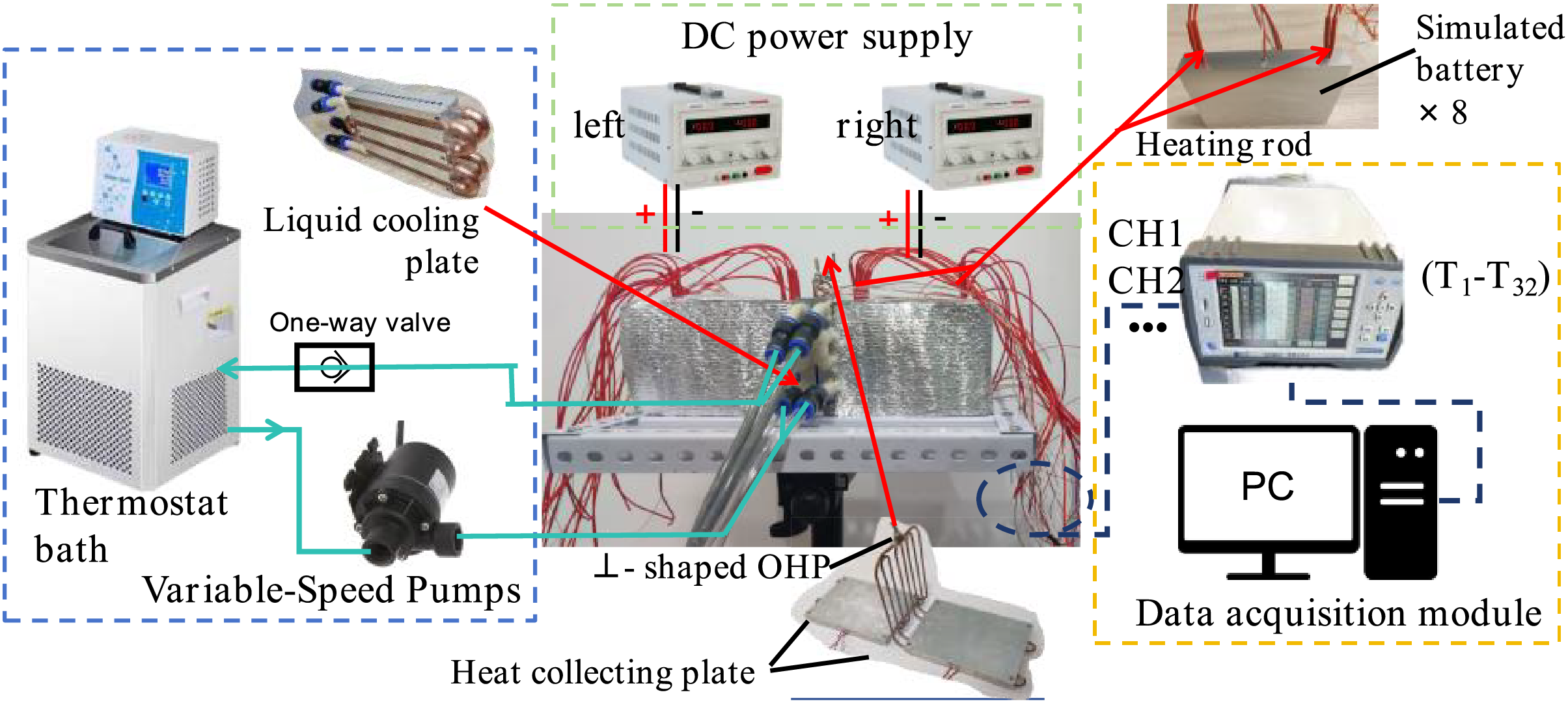
Figure 2: Schematic diagram of the test bench
This study focuses on eight batteries to determine the dimensions of the OHP, liquid cooling plate, and heat collection plate. However, actual battery pack typically contains a much larger number of cells. In practice, owing to the easy manufacturability and high adaptability of oscillating heat pipes, the hybrid BTMS is modular and can be flexibly designed with dimensions tailored to match the specific number of cells required in real-world applications.
The liquid cooling plate consists of two detachable plates, each measuring 120 mm × 100 mm × 15 mm, fastened together with bolts. This plate is designed to dissipate heat directly from the battery surface and to remove heat from the condenser section of the OHP. One side of the liquid cooling plate features semi-circular grooves with both the number and diameter matching those on the heat-collecting plate, allowing for the installation of the OHP’s condenser section. The opposite side has four 8 mm-deep channels that accommodate square copper tubes with an outer diameter of 8 mm, forming cooling channels that make flush contact with the battery surface.
The experiment utilized an MS10030D DC power supply to power the heat source. It is important to note that the primary focus of this study is on OHPs with different structural designs and the hybrid BTMS based on the ⊥-shaped OHP. When examining the startup and heat transfer performance of OHPs under various structural parameters, it is critical to ensure that the heat source does not come into direct contact with the liquid cooling plate, so that heat transfer occurs exclusively through the OHP.
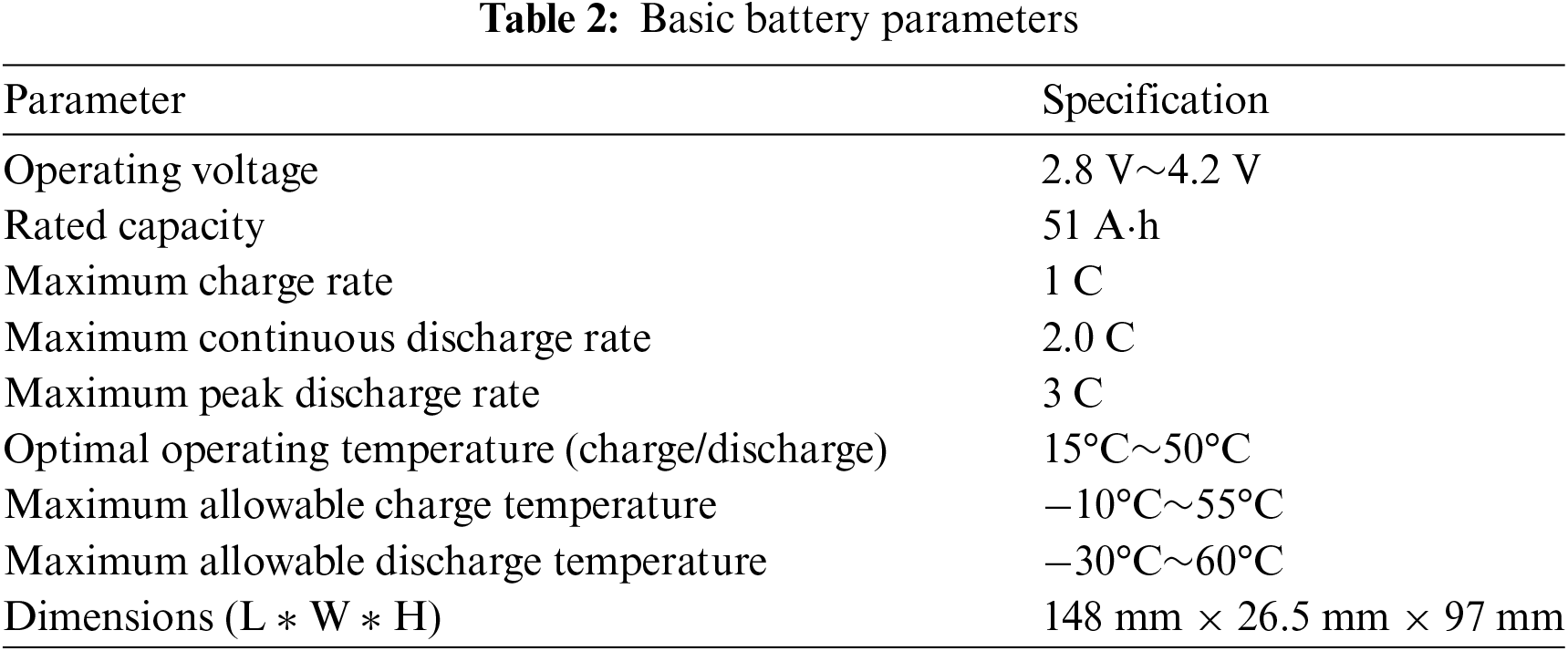
As shown in Fig. 3, heat input to the OHP is provided by a metal heating film (encased in polyimide material) attached to the heat collector plate of the evaporator section. For consistency, two metal heating films were used in each OHP BTMS with different structures. For the hybrid BTMS experiments, the heat source is a simulated battery pack made of eight aluminum blocks, substituting for the LP-51A·h ternary prismatic lithium-ion battery produced by Lishen Company. This lithium-ion battery model is widely used in the electric vehicle industry [39,40]. The basic parameters of the battery are listed in Table 2. Each aluminum block measured 148 mm × 26 mm × 97 mm, with circular holes (6 mm in diameter and 70 mm deep) machined at the electrode positions to house 6 mm × 60 mm heating rods. These heating rods were used to simulate the battery’s heat generation under various operating conditions. A PT100 temperature sensor was installed in the center of each simulated battery to monitor and record real-time temperature variations in the core areas of the cells.
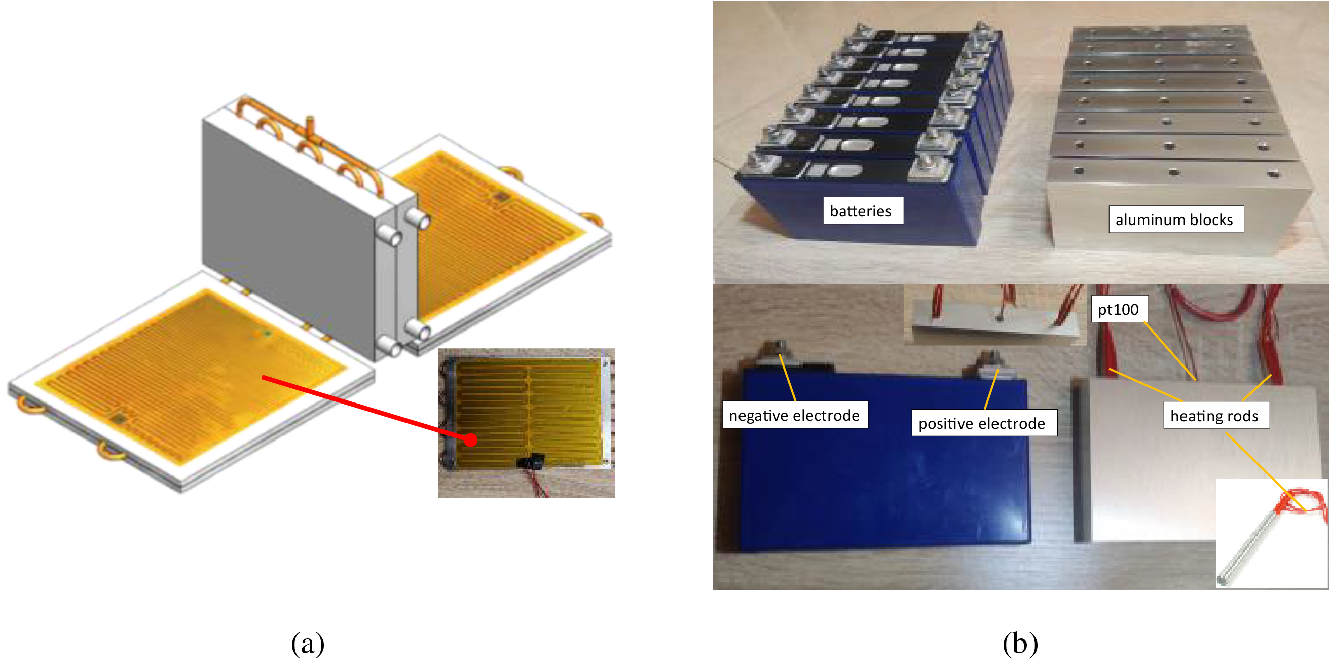
Figure 3: (a) Heat source used in the study on OHP; (b) heat source used in the study on hybrid BTMS
Similar to many studies on OHP-based BTMS, this study also uses same-sized heated aluminum blocks as substitutes for the heat generated by battery cells [22,26,27]. It is important to note that the calculation of the simulated battery’s heat release rate in this study is based on the Bernardi equation [41], which estimates heat generation by measuring the internal resistance and open-circuit voltage of sample cells during charging and discharging. This method reflects the average thermal power for specific discharge rates over time, which differs from the instantaneous thermal power of actual cells. The battery is permitted to operate at a maximum discharge rate of 3 C. In the experiment, the equivalent heat loads for the battery pack at discharge rates of 0.75, 1.5, and 3 C are 29.6, 90.4, and 277.6 W, respectively [39,40]. In this paper, the equivalent heat release power at the maximum discharge rate is used to evaluate the cooling performance advantages of the hybrid system.
Based on the dimensions of the battery pack, the primary specifications of the copper OHP used in the experiment include an outer diameter of 3 mm, an inner diameter of 2 mm, and four bends with a radius of 7 mm. The straight section length of the evaporator is 148 mm, while the condenser’s straight section length is 97 mm. During the fabrication of the OHP, measures were taken to ensure its airtightness. The connection between the oscillating heat pipe and the filling port was secured with silver brazing. After filling, the port was sealed twice using crimping pliers to prevent any leakage.
It is important to note that due to manufacturing tolerances in OHP fabrication, the theoretical volume formula for thermal management cannot be directly used to calculate the OHP volume. To determine the OHP volume, the pipe should first be completely filled with deionized water, and then the volume of the deionized water should be measured to obtain the OHP volume. The filling ratio of the OHP is defined as the ratio of the working fluid volume injected into the OHP to the total volume of the OHP. For example, a working fluid volume of 1.5 mL corresponds to a filling ratio of 19.6%.
Gravity significantly influences the movement of the working fluid within the OHP. When the condenser is positioned above the evaporator, gravity assists the flow of the two-phase working fluid. Conversely, if the evaporator is positioned above the condenser, gravity acts as a resistance rather than a driving force, greatly reducing the OHP’s performance and potentially rendering it inoperative. As shown in Fig. 4a, a conventional OHP with the evaporator, adiabatic, and condenser sections aligned in the same plane is referred to as a 2D-OHP. Following the design principle of positioning the condenser above the evaporator, two new OHP structures were developed for the novel hybrid BTMS, as illustrated in Fig. 4b,c. The structure with a vertically arranged condenser is named the ⊥-shaped OHP, while the structure with a horizontally arranged condenser is named the T-shaped OHP.
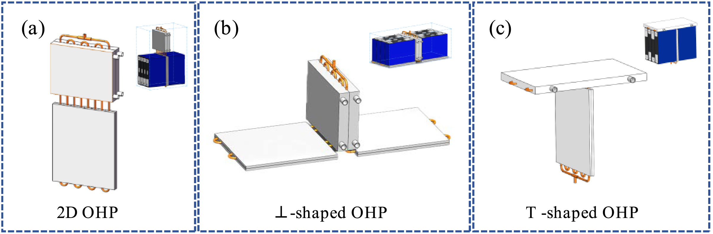
Figure 4: Structural diagrams of OHP used in experiment: (a) 2D-OHP (control group); (b) ⊥-shaped OHP; (c) T-shaped OHP
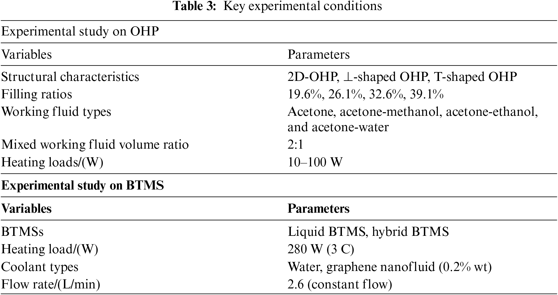
The experimental research in this study consists of two parts. First, the effects of filling ratio, mixed working fluids, and heat load on the performance of the ⊥-shaped OHP and T-shaped OHP are investigated, with the 2D-OHP serving as the control group. Based on the optimized results, the second part of the study compares the heat transfer characteristics of the hybrid BTMS based on the ⊥-shaped OHP with those of a liquid BTMS control group, as shown in Fig. 5. Additionally, the study examines the heat transfer enhancement characteristics of the Hybrid BTMS based on the ⊥-shaped OHP, using both pure water coolant and graphene nanofluid coolant with a mass fraction of 0.2%. In all experiments, the ambient temperature and the cooling liquid temperature in the heat dissipation system were maintained at 25°C. The variables and parameters involved in the experiments are listed in Table 3.
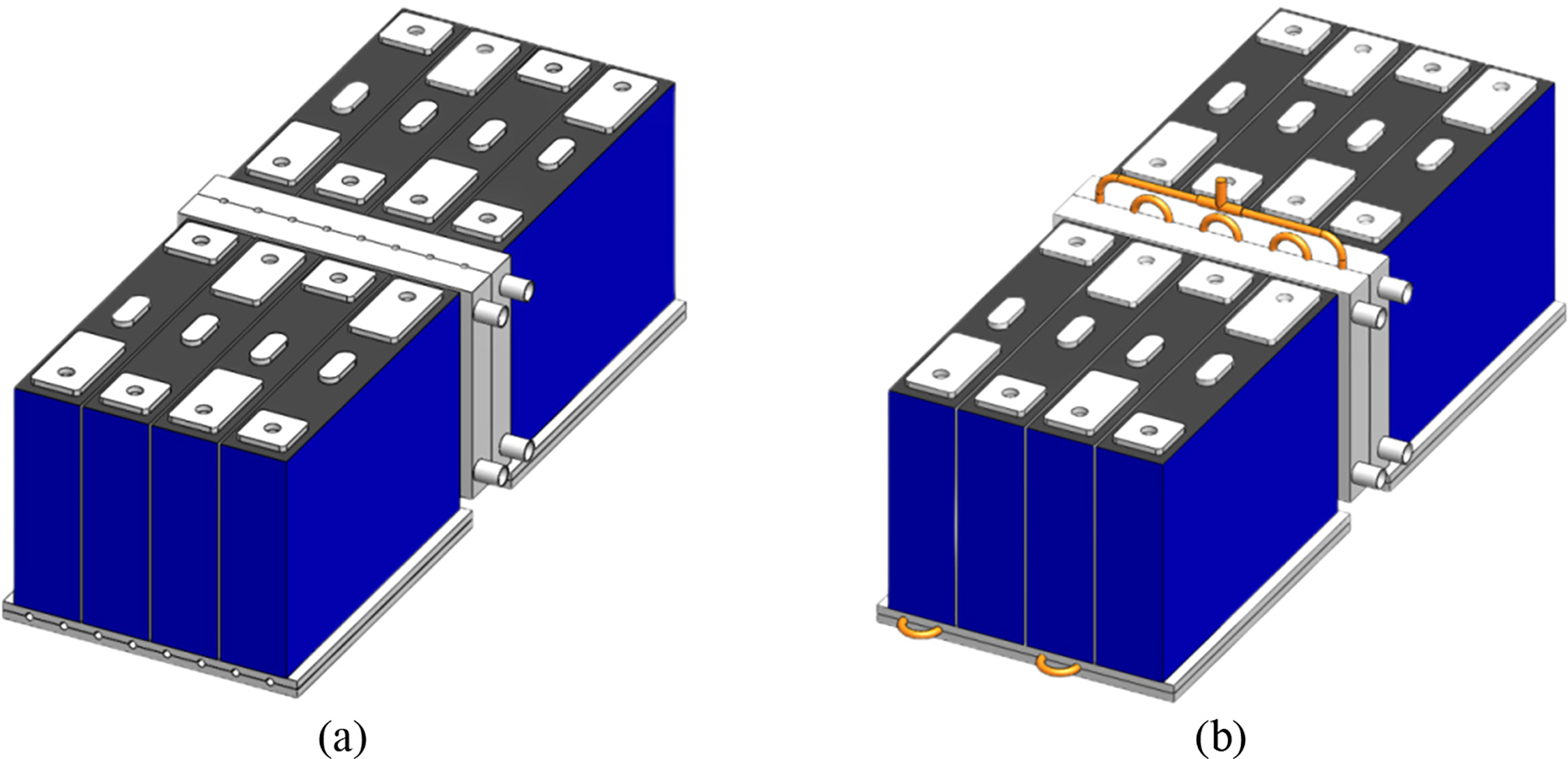
Figure 5: Different BTMSs used in experiment: (a) liquid BTMS (control group); (b) hybrid BTMS with ⊥-shaped OHP
During the experimental preparation phase, the experimental testing platform was assembled according to the schematic diagram of the testing apparatus. The heating, cooling, and temperature acquisition devices were then inspected and calibrated to ensure proper operation. After preparing and calibrating the experimental apparatus, experiments were conducted on the various variable parameters. Although the specific research parameters differed between each set of experiments, to ensure the accuracy of the measurements, the heat source was only turned off, and the experiment was stopped after the OHP had reached a stable state or had been running for over 2000 s, with the heat source temperature exceeding 60°C. During this period, temperature-time data were recorded and saved. Following each experiment, the liquid cooling system remained operational until the temperature at all measurement points returned to ambient levels. Before initiating the next set of experiments, a one-hour waiting period was observed to allow the gas and liquid plugs within the OHP to return to a randomly distributed steady state, preventing the results of the previous experiment from influencing the subsequent one. It is worth noting that under conditions where the OHP cannot operate stably (at low loads), the initiation and cessation of oscillations occur somewhat randomly. In such cases, three sets of tests are conducted under identical conditions, and the average of the measured results is taken to enhance the reliability of the data.
2.3 Data Acquisition and Processing
Due to the inherent randomness of the working fluid movement inside the OHP, it is essential to account for temperature variations at different locations when positioning the thermocouples. In all experiments, the temperature measurement points on the OHP were distributed as shown in Fig. 6a. Temperature collection points T1 to T4 were located on the evaporator section, T5 to T8 on the adiabatic section, and T9 to T12 on the condenser section. As illustrated in Fig. 6b, when studying the effects of structural parameters on OHP performance, metal heating films were used, and temperature data for the heat source were collected by measuring the temperature on the heat collector plate in the evaporator section. For the hybrid BTMS experiments, simulated batteries were used as the heat source, and surface temperature monitoring was conducted for simulated batteries 1, 3, 6, and 8. The temperature collection points for each simulated battery were the same. Taking simulated battery 1 as an example (as shown in Fig. 6c), the center temperature was recorded by a probe-type PT100 sensor at T15, while T13 and T14 measured the temperature near the heat collector plate, and T16 and T17 measured the temperature farther from the heat collector plate. Additionally, T13 and T16 were positioned closer to the liquid cooling plate.
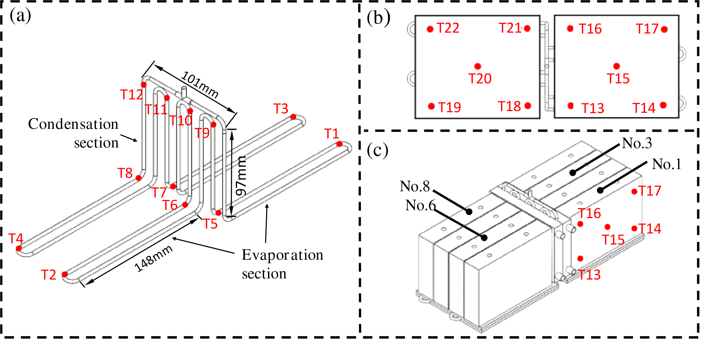
Figure 6: Layout of temperature measuring points: (a) temperature measurement points on OHP; (b) temperature measurement points on heat collecting plates; (c) temperature measurement points on the No. 1 cell
The performance of the OHP can be evaluated using thermal resistance. The definition of thermal resistance R is expressed in Eq. (1) as follows:
In the equation, Teva and Tcon represent the average wall temperatures of the evaporation and condensation sections, respectively, and QOHP refers to the heat transfer capacity of the OHP. n1 and n2 denote the number of temperature measurement points arranged in the evaporation and condensation sections, respectively. The unit of thermal resistance R is °C/W.
In addition to thermal resistance, another key performance metric of the OHP is the evaporator temperature at the moment the OHP starts operating. The variation in evaporator temperature during stable operation is also an important indicator. The thermal stability of the OHP can be evaluated using the standard deviation
where: Teva, i is the temperature at the i-th measurement point in the evaporator, n is the number of temperature measurement points in the evaporation section.
The cooling performance of a BTMS can be directly evaluated through the temperature and temperature difference of the battery pack. The better the cooling performance, the lower the maximum and average surface temperatures of the battery, and the smaller the temperature difference. Therefore, this study focuses on the following key parameters: average battery temperature (Tb), maximum battery temperature (Tmax), Maximum temperature difference (ΔTmax), and the BTMS equivalent thermal resistance (RBTMS). The definitions of these parameters are as follows:
In these contexts, n refers to the number of temperature measurement points within the battery pack, and Ti is the surface temperature at the i-th measurement point. Tout represents the outlet temperature of the cooling liquid.
To facilitate a comparison of the performance advantages of the hybrid BTMS with dual heat transfer paths over the traditional liquid BTMS, a performance enhancement index (EP) can be defined. This index evaluates the enhancement of key parameters under different conditions, including Tb, Tmax, ΔTmax, and RBTMS. The performance enhancement indices for
In these contexts,
During the experiment, the experimental errors mainly consist of direct measurement errors and indirect measurement errors. Based on the error propagation law [42], the formula for calculating the error is as follows:
This study primarily investigates the ⊥-shaped OHP and the hybrid BTMS based on the ⊥-shaped OHP. In the experiments, the main sources of direct measurement errors arise from the temperature data collected from various points on the battery pack and the OHP. Indirect measurement errors are associated with the heat source power and thermal resistance. The uncertainties and accuracy of the instruments used in the experiments are listed in Table 1. By addressing these errors, the reliability of the measurements and results is ensured, and the propagation of uncertainties is carefully considered throughout the experimental process. Using the error propagation law and combining it with Eq. (13), the indirect measurement errors for the heat load Q and the thermal resistance R of the OHP can be calculated as follows:
As the heat load decreases, the uncertainty in measurement error increases, assuming the precision of the equipment remains constant. Conversely, as the heat load increases, both the measurement error and the indirect error decrease significantly. Based on the previously mentioned formulas, at the minimum heat load in the experiment, the uncertainty of the heat load Q is 1.9%, and the corresponding uncertainty for the thermal resistance R is 3.8%.
3.1 Thermal Performance of the Vertically Structured OHP
3.1.1 Effect of Filling Ratios
The normal operating temperature of a BTMS typically does not exceed 55°C. If the OHP fails to initiate within this temperature range, the OHP-based BTMS is considered nonfunctional. The filling ratio (FR) of the working fluid significantly influences the initial distribution of liquid and vapor plugs within the OHP, which plays a critical role in both startup and stable operation [34]. As shown in Fig. 7, an experimental investigation was conducted to evaluate the effects of filling ratios on the startup and heat transfer performance of three OHP configurations—⊥-shaped OHP, T-shaped OHP, and 2D-OHP—using acetone as the working fluid under a relatively low heat load of 30 W. Theoretically, a lower filling ratio reduces frictional resistance between the liquid plugs and the pipe walls, promoting smoother fluid motion and improving the startup performance of the OHP. However, an excessively low filling ratio results in a reduced volume of working fluid within the system. The efficient heat transfer mechanism in OHPs relies on the rapid fluid motion between the evaporator and condenser sections, which encompasses both latent heat transfer during phase change and sensible heat transfer of the liquid. Extensive experimental studies have demonstrated that sensible heat transfer constitutes the majority of the heat exchange process in OHPs [35]. Consequently, when the filling ratio is too low, the sensible heat transferred during fluid motion from the evaporator to the condenser is diminished. This limitation adversely affects the overall heat transfer performance and constrains the OHP’s capacity for efficient thermal management.
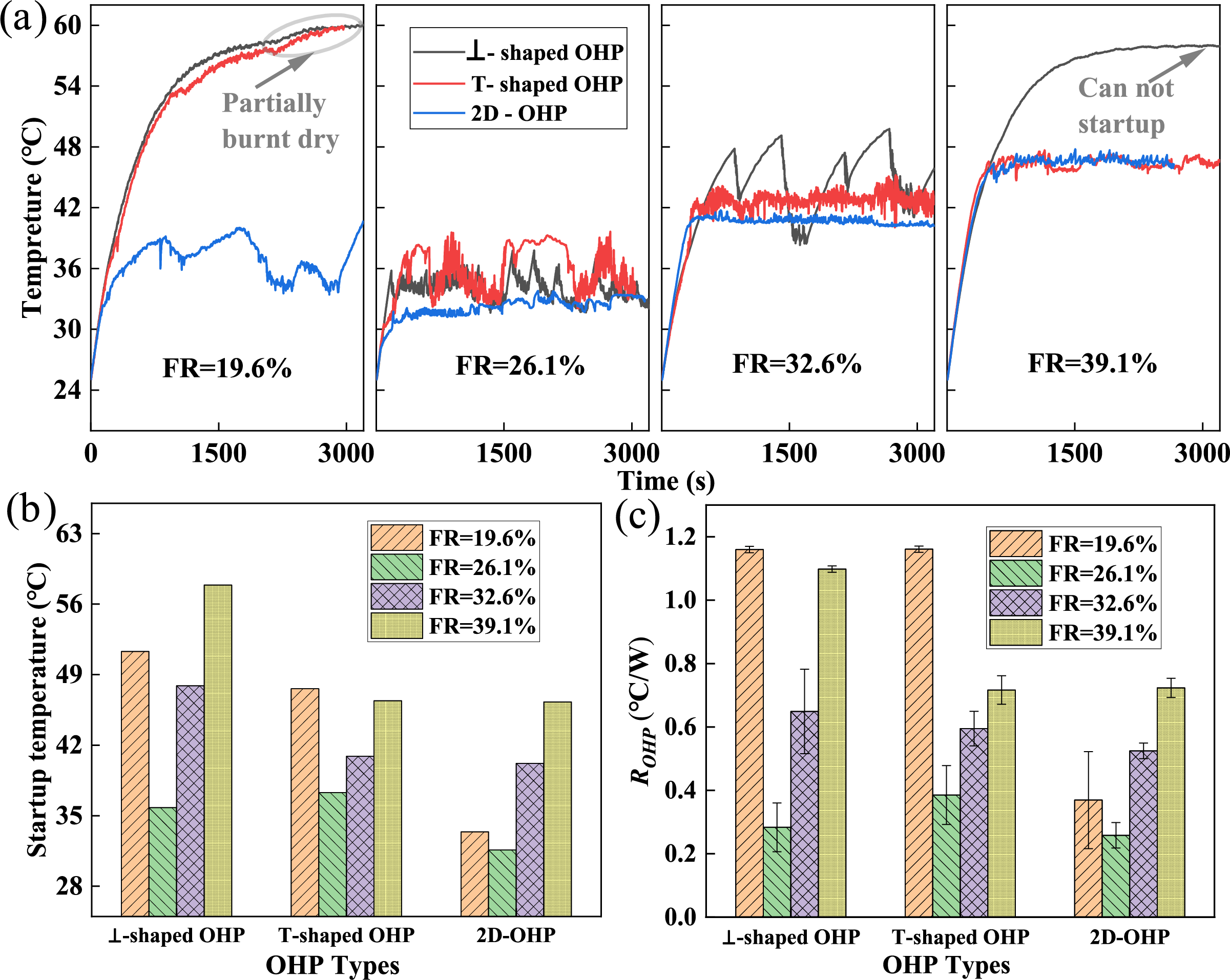
Figure 7: (a) Temperature oscillation curves of ⊥-shaped OHP, T-shaped OHP, and 2D-OHP under filling ratios between 19.6% and 39.1%; (b) startup temperatures of various OHPs under different filling ratios; (c) thermal resistance (ROHP) changes of various OHPs under different filling ratios
Fig. 7a illustrates the temperature oscillation curves at the evaporator section (T2) of the OHP under various filling ratios. At a filling ratio of 19.6%, both the ⊥-shaped OHP and the T-shaped OHP exhibit localized dry-out in the evaporator section due to an insufficient quantity of working fluid, rendering them nonfunctional. Among the three OHP configurations examined, the lowest operating temperature is achieved at a relatively low filling ratio of 26.1%. However, as the filling ratio increases beyond this value, the startup performance of the OHPs progressively declines. For the T-shaped OHP and the 2D-OHP, higher filling ratios contribute to improved operational stability. In contrast, the startup performance of the ⊥-shaped OHP is particularly sensitive to variations in the filling ratio. Under low heat loads, the ⊥-shaped OHP fails to initiate at a filling ratio of 39.1%, underscoring its pronounced dependency on the optimal distribution of the working fluid for successful operation.
Fig. 7b,c presents the startup temperatures and thermal resistances of the three OHP configurations under varying filling ratios. The conventional 2D-OHP demonstrates the best performance, with a thermal resistance of 0.72 °C/W at a filling ratio of 39.1%. This result aligns with the findings of Wei et al. [19], who used a similar 2D-OHP. In their study, employing the same coolant temperature, a comparable acetone filling ratio (40%), and a similar heat load (32 W), they measured a thermal resistance of 0.68 °C/W. This consistency indirectly validates the reliability of the experimental setup used in this study. Compared to the 2D-OHP, both the ⊥-shaped OHP, with its horizontally arranged evaporator section, and the T-shaped OHP, with its horizontally arranged condenser section, exhibit diminished startup and heat transfer performance. This decline is reflected in significantly higher startup temperatures and thermal resistances for these two configurations. The primary cause of this performance degradation is the absence of gravity as a driving force in the horizontally arranged sections, a limitation that is particularly pronounced under low heat loads. Since the OHP’s startup process is initiated by the heat source at the evaporator section, the ⊥-shaped OHP requires a larger temperature gradient to generate sufficient driving force for startup due to its horizontal evaporator configuration. In contrast, the T-shaped OHP faces fewer constraints in this regard. This disparity highlights the increased sensitivity of the ⊥-shaped OHP’s performance to variations in filling ratios under low heat load conditions.
3.1.2 Effect of Working Fluids
The exceptional heat transfer performance of OHPs is fundamentally attributed to their thermally driven, self-excited oscillations, with the physical properties of the working fluid playing a pivotal role in influencing their startup and heat transfer performance. Commonly used working fluids in OHP research include deionized water, methanol, ethanol, and acetone. In this study, as illustrated in Fig. 8, the thermal performance of ⊥-shaped OHP, T-shaped OHP, and 2D-OHP was evaluated under a heat load of 30 W using mixed working fluids. Acetone, selected as the base fluid due to its low boiling point and latent heat, was combined with another fluid in a 2:1 volume ratio to form the mixture.
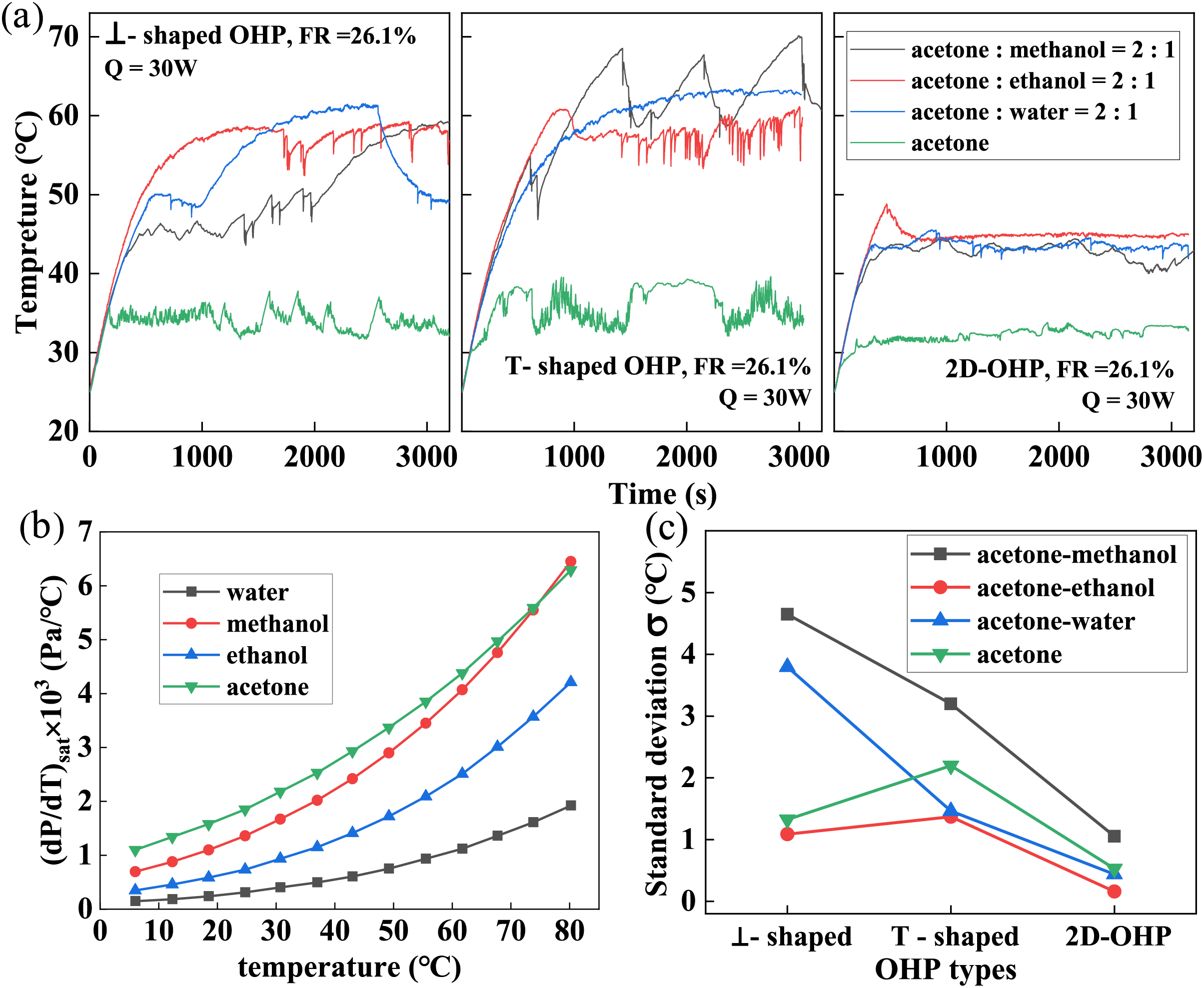
Figure 8: (a) Temperature oscillation curves of various OHPs under the mixed working fluids: acetone—methanol volume ratio = 2:1, acetone—ethanol volume ratio = 2:1, acetone—water volume ratio = 2:1, and acetone; (b) saturation pressure gradient (dP/dT)sat curves of different working fluids; (c) temperature standard deviation
Fig. 8a depicts the temperature variation curves of the evaporator section for different OHP configurations with various mixed working fluids. Among the vertically configured OHPs, the acetone/methanol mixture demonstrates superior startup performance compared to other mixtures. However, its operational stability is relatively poor. Specifically, after startup, the ⊥-shaped OHP experiences localized dry-out over time, while the T-shaped OHP exhibits periodic low-frequency oscillations with temperature amplitudes exceeding 10°C. In contrast, OHPs using acetone/ethanol mixtures display higher startup temperatures than those using acetone/methanol mixtures, attributable to ethanol’s lower saturation pressure gradient (dP/dT)sat, as shown in Fig. 8b. Additionally, the temperature oscillations of OHPs with ethanol mixtures are more stable, characterized by smaller fluctuations. Notably, although water has a higher boiling point than ethanol and the lowest saturation pressure gradient—factors that theoretically indicate poorer startup performance for acetone/water mixtures—the ⊥-shaped OHP achieves a lower startup temperature with acetone/water than with acetone/ethanol mixtures. This anomaly is primarily attributed to the phase-change suppression characteristics of the acetone/water mixture. In this case, water remains predominantly in the liquid phase within the heat pipe, enhancing the sensible heat transfer capability of the working fluid.
Fig. 8c shows the standard deviation of temperatures in the 1000–3000 s interval for various OHP configurations with different mixed working fluids. The data reveal that, irrespective of the working fluid used, the 2D-OHP exhibits significantly smaller temperature standard deviations, ranging from 0.16°C to 1.1°C, compared to the two vertically configured OHPs. This finding suggests that, under a 30 W heat load, the vertical configuration of OHPs compromises heat transfer stability. Among the mixed working fluids, the acetone/ethanol mixture consistently achieves the lowest temperature standard deviations across all OHP configurations, indicating minimal temperature variation in the evaporator section and superior operational stability. In contrast, methanol-based mixtures result in the highest temperature standard deviations for all OHP designs. This instability is primarily attributed to methanol’s higher volatility, which increases the likelihood of vaporization and the subsequent formation of dry-out zones in the evaporator section.
Fig. 9 presents the temperature oscillation curves at the T2 point in the evaporator section for ⊥-shaped OHP, T-shaped OHP, and 2D-OHP under heat loads of 10, 50, and 100 W. To evaluate the transient effects of heat load on evaporator temperatures, the instantaneous temperature variation rate was analyzed over a 1000 s interval during steady operation. Fig. 9a–c depicts the temperature oscillation curves for the different OHP configurations under a 10 W heat load. For the ⊥-shaped OHP, oscillations are not initiated until the evaporator temperature reaches 41°C, at which point low-temperature working fluid from the condenser section surges into the evaporator, temporarily reducing the temperature. This behavior is followed by a cessation of oscillations, reflecting intermittent operation. In contrast, the T-shaped OHP and the 2D-OHP, both featuring vertically arranged evaporators, successfully initiate oscillations and achieve steady operation at an evaporator temperature of approximately 30°C. However, the horizontally arranged condenser in the T-shaped OHP impedes the return flow of low-temperature liquid from the condenser to the evaporator. As a result, compared to the 2D-OHP, the T-shaped OHP exhibits larger temperature oscillation amplitudes, higher transient temperature variation rates, and intervals of oscillation cessation. These observations suggest that the oscillatory behavior of the working fluid in the T-shaped OHP is inherently intermittent.
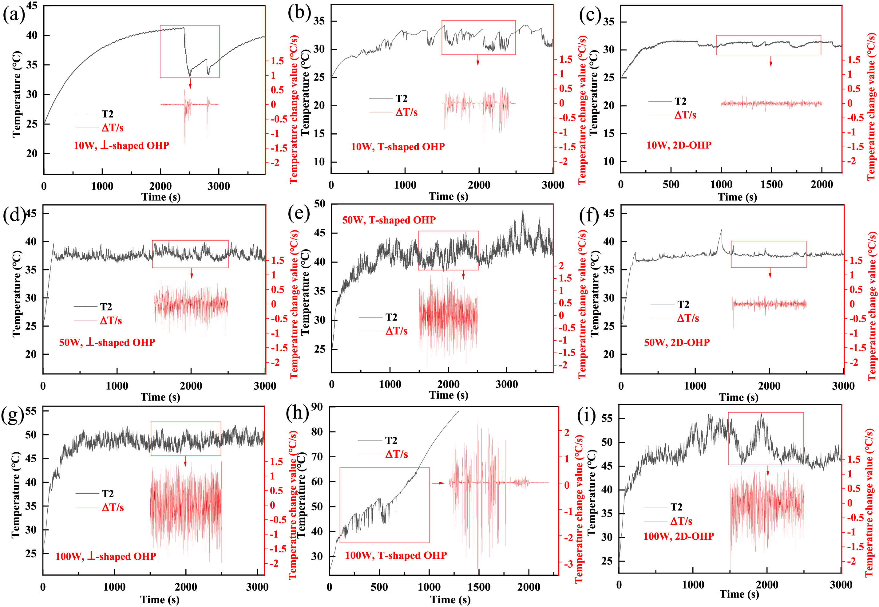
Figure 9: Temperature oscillation curves at the evaporation section (T2): (a) 10 W, ⊥-shaped OHP; (b) 10 W, T-shaped OHP; (c) 10 W, 2D-OHP; (d) 50 W, ⊥-shaped OHP; (e) 50 W, T-shaped OHP; (f) 50 W, 2D-OHP; (g) 100 W, ⊥-shaped OHP; (h) 100 W, T-shaped OHP; (i) 100 W, 2D-OHP
Fig. 9d–f presents the temperature oscillation curves for different OHP configurations under a heat load of 50 W. With increasing heat load, the operating temperatures of the evaporator sections rise across all three configurations. The 2D-OHP exhibits minimal temperature oscillation amplitudes and a transient temperature variation rate of approximately 0.3 °C/s, signifying stable operation. In contrast, the two vertically configured OHPs display larger temperature oscillation amplitudes. The ⊥-shaped OHP maintains relatively stable oscillations, with a transient temperature variation rate below 1 °C/s. However, the T-shaped OHP experiences intense oscillations within the 38°C–47°C temperature range, with transient temperature variation rates exceeding 1.5 °C/s. These results indicate that as the heat load increases, the operational stability of the T-shaped OHP declines, revealing a lower heat transfer limit compared to the other configurations.
Fig. 9g–i depicts the temperature oscillation curves for different OHP configurations under a heat load of 100 W. At this load, the ⊥-shaped OHP demonstrates excellent operational stability, maintaining a transient temperature variation rate of approximately 1.5 °C/s. In contrast, the T-shaped OHP initiates oscillations when the evaporator temperature reaches approximately 40°C. However, these oscillations become progressively steeper, with the transient temperature variation rate peaking at 3.0 °C/s. At around 720 s, oscillations cease entirely in the T-shaped OHP, leading to a sharp temperature rise and indicating heat pipe failure. This behavior confirms that the heat transfer limit of the T-shaped OHP is exceeded at 100 W. Notably, under the same heat load, the 2D-OHP operates within a temperature range of 44°C–55°C but exhibits significant temperature fluctuations. These fluctuations suggest that the heat transfer performance of the 2D-OHP under these conditions is inferior to that of the ⊥-shaped OHP.
Fig. 10a illustrates the variation in thermal resistance for the ⊥-shaped OHP, T-shaped OHP, and 2D-OHP across different heat loads. As the heat load increases, the thermal resistance of all OHP configurations initially decreases rapidly, then stabilizes, and eventually rises slightly after reaching a minimum value. The structural design of the OHP plays a critical role in determining its thermal performance. Compared to the 2D-OHP, the ⊥-shaped OHP encounters challenges during startup at low heat loads (<30 W), while the T-shaped OHP successfully starts at 10 W but suffers from poor operational stability and a maximum heat transfer limit of only 60 W. Notably, at higher heat loads (>70 W), the thermal resistance of the ⊥-shaped OHP is lower than that of the 2D-OHP. At 100 W, the 2D-OHP exhibits an average thermal resistance of approximately 0.25 °C/W, whereas the ⊥-shaped OHP achieves a lower average thermal resistance of 0.23 °C/W, demonstrating superior heat transfer performance under high heat load conditions.
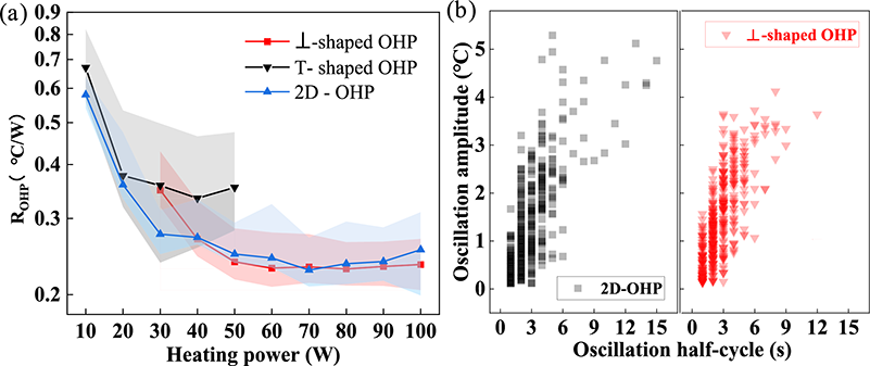
Figure 10: (a) The thermal resistance (ROHP) curves of various OHPs under different heating loads; (b) temperature oscillation amplitude and cycle in the evaporation section of ⊥-shaped OHP and 2D-OHP (100 W)
Fig. 10b illustrates the distribution characteristics of temperature oscillation amplitude and period on the evaporator wall for the ⊥-shaped OHP and the 2D-OHP under a heat load of 100 W. Consistent with the thermal resistance trends presented in Fig. 10a, the 2D-OHP exhibits poor temperature oscillation stability at this heat load. A significant number of oscillation amplitude data points cluster around 5°C, with half-periods exceeding 9 s. These observations indicate that a 100 W heat load is close to the heat transfer limit of the 2D-OHP. In contrast, the ⊥-shaped OHP displays a more concentrated distribution of temperature oscillation amplitude and period under the same conditions. This suggests that the oscillatory behavior of the working fluid in the ⊥-shaped OHP remains relatively stable even at high heat loads, underscoring its superior heat transfer capacity and higher heat transfer limit compared to the 2D-OHP.
3.2 Mechanism Analysis of the Vertically Structured OHP
To better elucidate the effects of structural configuration, filling ratio, working fluid type, and heat load on OHP performance, this study employs a simplified mathematical model to analyze the physical dynamics of vertically structured oscillating heat pipes. The plug/slug flow within the OHP is primarily driven by the pressure difference between the evaporator and condenser sections. Specifically, each liquid plug, isolated by adjacent vapor plugs on either side, is propelled by the pressure gradient between these vapor plugs, enabling oscillatory motion and efficient heat transfer.
As illustrated in Fig. 11, using the liquid plug at point C in the evaporator section as an example, the pressure difference generated by the driving force must overcome multiple resistances to enable stable movement of the liquid plug. These resistances include the capillary pressure drop (∆pca), frictional pressure drop (∆pf), dynamic pressure drop due to velocity changes (∆pu), and gravitational pressure drop (∆pg). The driving force for the liquid plug’s motion can thus be expressed using the following equation:
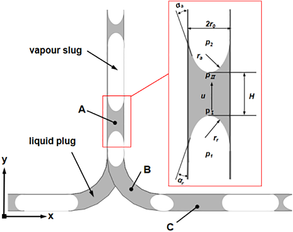
Figure 11: Pressure analysis of the liquid slug in the OHP
Using Ling’s calculation method [43], the following assumptions were made:
• The liquid plug moves at a constant velocity during stable operation.
• The gas within the heat pipe is treated as an ideal gas, and friction between the gas and the pipe wall is neglected.
• The influence of gravity on the gas is ignored.
Based on these assumptions, the calculated results for the various pressure drops are summarized in Table 4.
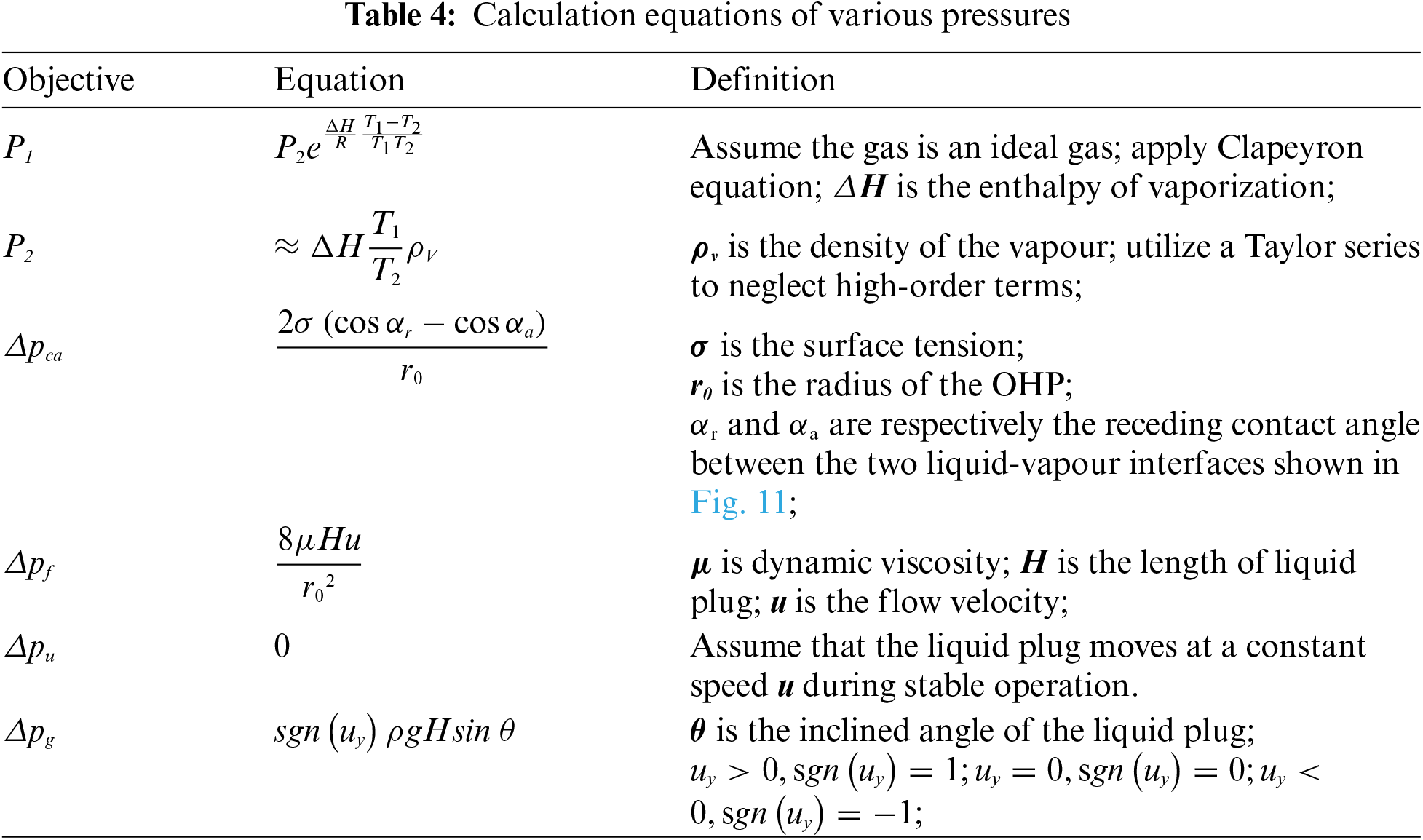
The sum of various pressure differences is represented as Eq. (17).
The driving force is given by Eq. (18).
During the startup of the oscillating heat pipe, the behavior is characterized by the low-temperature working fluid from the condenser section flowing into the evaporator section. At this point, the expression for gravitational pressure drop (∆pg) can be simplified as Eq. (19).
During the startup phase, gravity contributes as part of the driving force. For 2D-OHP and T-shaped OHP, the evaporator sections are vertically arranged, with θ = 90°, making sinθ = 1. This configuration allows both 2D-OHP and T-shaped OHP to utilize gravity to assist in the startup process. In contrast, the evaporator section of the ⊥-shaped OHP is horizontally arranged, with sinθ = 0, meaning it cannot rely on gravity for startup. As a result, additional driving forces are required to initiate operation. This disadvantage is more pronounced under low heat loads, explaining why the ⊥-shaped OHP exhibits poorer startup performance in such conditions.
From Eq. (17), it can be inferred that a lower filling ratio results in a shorter liquid plug length (H) within the pipe. This reduction in liquid plug length decreases the overall pressure drop inside the pipe, thereby reducing the required driving force. This phenomenon explains why oscillating heat pipes exhibit improved startup performance at lower filling ratios. Furthermore, as indicated in Eq. (18), the driving force is determined by the temperature difference across the liquid plug. Employing a working fluid with a higher saturation pressure gradient significantly enhances the driving pressure. Additionally, as the heat load increases, the temperature difference across the liquid plug grows, resulting in a corresponding increase in the driving force.
3.3 Thermal Performance of the Hybrid BTMS
Compared to the T-shaped OHP, the ⊥-shaped OHP demonstrates superior heat transfer performance and more stable operation under high loads. Additionally, even if a working fluid leak occurs, gravity causes the fluid to seep from the bottom of the heat collection plate rather than onto the battery pack surface. Therefore, this study utilizes the ⊥-shaped OHP to investigate the performance characteristics of the proposed hybrid BTMS. Under a 3C discharge rate, the battery pack generates approximately 280 W of heat load.
Fig. 12 shows the steady-state temperature values at each measurement point on the battery pack under a 280 W heat load for both the liquid BTMS and hybrid BTMS, using different types of cooling liquids. The temperature measurement points T13–T17, T18–T22, T23–T27, and T28–T32 correspond to the surface temperature points of batteries No. 1, No. 3, No. 6, and No. 8, respectively. In general, for both the hybrid BTMS and liquid BTMS, the temperature decreases as the measurement point gets closer to the cooling plate. The maximum temperature across all the batteries is observed at the points farthest from both the cooling plate and the evaporator section of the OHP, specifically at T17, T22, T27, and T32. Notably, T32 on battery No. 8 records the highest temperature among all measurement points.
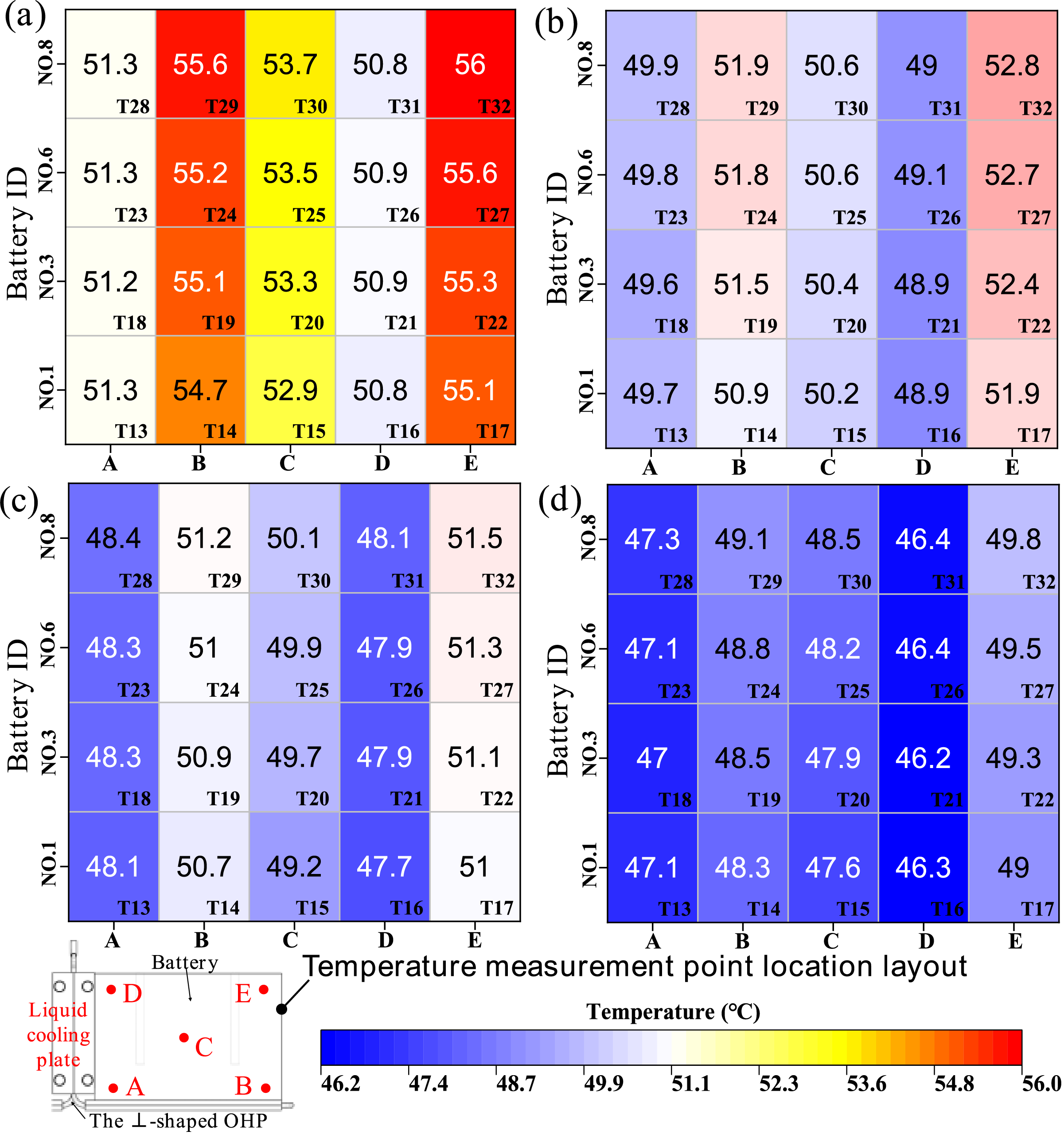
Figure 12: Temperatures at each measurement point of the battery pack under different BTMSs and coolant types (280 W): (a) liquid BTMS with water coolant; (b) hybrid BTMS with water coolant; (c) liquid BTMS with nanofluid coolant; (d) hybrid BTMS with nanofluid coolant
As depicted in Fig. 12a,b, when water is used as the coolant, the hybrid BTMS demonstrates significantly better cooling performance than the liquid BTMS due to its dual heat transfer paths. The temperature at the points farther from the liquid cooling plate in the hybrid BTMS (T14, T17, T19, T22, T24, T27, T29, T32) is approximately 3.2°C lower than in the liquid BTMS. This reduction in temperature helps lower the highest temperature in the battery pack and improves the overall temperature uniformity, which is beneficial for enhancing battery performance and longevity.
When using graphene nanofluid with a mass fraction of 0.2% as the cooling liquid, as shown in Fig. 12c,d, nanofluids significantly enhance the cooling performance of both the liquid BTMS and hybrid BTMS. Compared to the liquid BTMS, the hybrid BTMS—due to its dual heat transfer paths—continues to demonstrate superior heat transfer performance, with lower steady-state temperatures at all measurement points on the battery pack. In line with previous findings, the highest temperatures within the battery pack are observed at locations furthest from both the cooling plate and the evaporator section of the OHP, particularly at T17, T22, T27, and T32. In the hybrid BTMS, the temperatures at these points are 49.9°C, 49.3°C, 49.5°C, and 49.8°C, respectively. In contrast, in the liquid BTMS, the corresponding temperatures are 51.0°C, 51.1°C, 51.3°C, and 51.5°C. These results demonstrate that even with the enhanced cooling provided by the graphene nanofluid, the hybrid BTMS maintains a performance advantage over the liquid BTMS by providing better heat dissipation and lower overall temperatures.
Fig. 13a compares the average surface temperature, maximum temperature difference, and equivalent thermal resistance of the battery pack in both the hybrid BTMS and liquid BTMS under a 280 W heat load, using either water or graphene nanofluid as the cooling liquid. The cases are defined as follows:
• Case 1: liquid BTMS with water coolant,
• Case 2: hybrid BTMS with water coolant,
• Case 3: liquid BTMS with graphene nanofluid coolant,
• Case 4: hybrid BTMS with graphene nanofluid coolant.
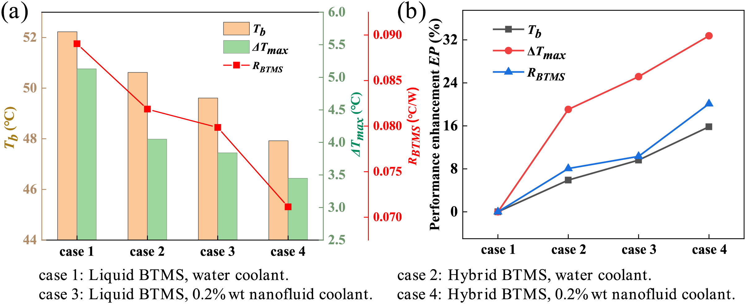
Figure 13: (a) Tb, ΔTmax, and RBTMS with different BTMS schemes (Q = 280 W); (b) performance enhancement index with different BTMS schemes (Q = 280 W)
As seen in the figure, Case 4 (hybrid BTMS with nanofluid) exhibits the best cooling performance, with optimal Tb of 47.9°C, ΔTmax of 3.45°C, and RBTMS of 0.071 °C/W. The superior performance of Case 4 is attributed to two factors: first, under a 280 W heat load, the working fluid inside the ⊥-shaped OHP continues to oscillate, activating the heat transfer path provided by the OHP in the hybrid BTMS; second, the use of graphene nanofluid greatly enhances the efficiency of the liquid cooling path. Notably, to maintain the average battery temperature below 50°C, existing studies on OHP-based BTMS have reported heat loads ranging only between 5 and 100 W [18–26,28]. This clearly demonstrates the performance advantage of the hybrid BTMS proposed in this study, which effectively expands the operational range and improves thermal management efficiency.
It is also worth noting that Case 3 (liquid BTMS with graphene nanofluid) outperforms Case 2 (hybrid BTMS with water). This indicates that, under a 280 W heat load, the improvement in cooling performance by adding 0.2% graphene nanofluid to the liquid BTMS is greater than the improvement achieved by adding the ⊥-shaped OHP to the hybrid BTMS alone. In Fig. 13b, with the liquid BTMS using conventional cooling liquid (Case 1) as the baseline, the degree of performance enhancement in the system when using hybrid BTMS and nanofluid is illustrated. When using the new hybrid BTMS (Case 2), the performance enhancements for Tb, ΔTmax, and RBTMS are 5.9%, 19.1%, and 8.06%, respectively. When graphene nanofluid is applied in the hybrid BTMS (Case 4), the performance improvements for Tb, ΔTmax, and RBTMS increase to 15.8%, 32.7%, and 20.1%, respectively.
This paper presents an experimental investigation of the proposed novel hybrid BTMS based on an OHP. Key findings include:
1. A filling ratio of 26.1% optimizes the ⊥-shaped OHP’s startup and thermal performance. Acetone demonstrates superior heat transfer at low loads, while the acetone-ethanol mixture minimizes temperature fluctuations.
2. Due to the influence of gravity, the ⊥-shaped OHP with a horizontally arranged evaporator section struggles to start under low heat loads but demonstrates stronger heat transfer performance under high loads compared to the standard 2D-OHP. Conversely, the T-shaped OHP with a horizontally arranged condenser section starts easily under low loads but exhibits poor operational stability as the load increases.
3. Compared to traditional OHP BTMS, the hybrid system extends the heat transfer limit from less than 100 W to over 280 W, making it particularly suitable for high-load BTMS applications and heat dissipation in high heat flux density devices.
4. Compared to the liquid BTMS, the hybrid BTMS adds an additional OHP heat transfer path, reducing the ΔTmax and RBTMS by 19.1% and 8.06%, respectively, under 280 W. Graphene nanofluid further improves performance, achieving reductions of 32.7% in ΔTmax and 20.1% in RBTMS.
5. Future work should focus on optimizing the hybrid BTMS structure for larger battery configurations, validating its performance with real battery packs under dynamic operational conditions, and enhancing its practical application by the studying the long-term reliability of the novel system.
Acknowledgement: The support for the laboratory used from Jiangxi Polytechnic University, China and Universiti Malaysia Pahang Al-Sultan Abdullah was equally acknowledged and appreciated.
Funding Statement: This research was funded by the Science and Technology Research Project of Jiangxi Provincial Department of Education (GJJ2404911), the Ministry of Higher Education, Malaysia through the Fundamental Research Grant Scheme: FRGS/1/2024/TK10/UMP/02/15 and Universiti Malaysia Pahang Al-Sultan Abdullah (RDU240117).
Author Contributions: The authors confirm contribution to the paper as follows: study conception and design: Hongkun Lu, M. M. Noor, K. Kadirgama; data collection: Hongkun Lu; analysis and interpretation of results: Hongkun Lu, M. M. Noor; supervision: M. M. Noor; draft manuscript preparation: Hongkun Lu, M. M. Noor, K. Kadirgama. All authors reviewed the results and approved the final version of the manuscript.
Availability of Data and Materials: The data are available from the corresponding author upon reasonable request.
Ethics Approval: Not applicable.
Conflicts of Interest: The authors declare no conflicts of interest to report regarding the present study.
References
1. Shrivastava P, Naidu PA, Sharma S, Panigrahi BK, Garg A. Review on technological advancement of lithium-ion battery state estimation methods for electric vehicle applications. J Energy Storage. 2023;64(1):107159. doi:10.1016/j.est.2023.107159. [Google Scholar] [CrossRef]
2. Jin C, Sun Y, Yao J, Feng X, Lai X, Shen K, et al. No thermal runaway propagation optimization design of battery arrangement for cell-to-chassis technology. eTransportation. 2022;14(7221):100199. doi:10.1016/j.etran.2022.100199. [Google Scholar] [CrossRef]
3. Pradhan R, Keshmiri N, Emadi A. On-board chargers for high-voltage electric vehicle powertrains: future trends and challenges. IEEE Open J Power Electron. 2023;4:189–207. doi:10.1109/OJPE.2023.3245149. [Google Scholar] [CrossRef]
4. Xiao Y, Zhao JR, Yin L, Li B, Tian Y. Staged thermal runaway behaviours of three typical lithium-ion batteries for hazard prevention. J Therm Anal Calorim. 2024;1–13. doi:10.1007/s10973-023-12267-y. [Google Scholar] [CrossRef]
5. Singh R, Oridate T, Nguyen T. Drive train cooling options for electric vehicles. Front Heat Mass Transf. 2024;22(3):703–17. doi:10.32604/fhmt.2024.050744. [Google Scholar] [CrossRef]
6. Sharma DK, Prabhakar A. A review on air cooled and air centric hybrid thermal management techniques for Li-ion battery packs in electric vehicles. J Energy Storage. 2021;41(2):102885. doi:10.1016/j.est.2021.102885. [Google Scholar] [CrossRef]
7. Chen K, Zhang Z, Wu B, Song M, Wu X. An air-cooled system with a control strategy for efficient battery thermal management. Appl Therm Eng. 2024;236:121578. doi:10.1016/j.applthermaleng.2023.121578. [Google Scholar] [CrossRef]
8. Zhao G, Wang X, Negnevitsky M, Li C. An up-to-date review on the design improvement and optimization of the liquid-cooling battery thermal management system for electric vehicles. Appl Therm Eng. 2023;219(11):119626. doi:10.1016/j.applthermaleng.2022.119626. [Google Scholar] [CrossRef]
9. Naphon P, Assadamongkol P, Borirak T. Flow direction effects on temperature distribution of Li-ion cylindrical battery module with water/ferrofluid as coolants. Front Heat Mass Transf. 2022;19:31. doi:10.5098/hmt.19.31. [Google Scholar] [CrossRef]
10. Cai S, Zhang X, Ji J. Recent advances in phase change materials-based battery thermal management systems for electric vehicles. J Energy Storage. 2023;72(9):108750. doi:10.1016/j.est.2023.108750. [Google Scholar] [CrossRef]
11. Yu Z, Zhang J, Pan W. A review of battery thermal management systems about heat pipe and phase change materials. J Energy Storage. 2023;62(5):106827. doi:10.1016/j.est.2023.106827. [Google Scholar] [CrossRef]
12. Fathoni AM, Putra N, Mahlia TI. A systematic review of battery thermal management systems based on heat pipes. J Energy Storage. 2023;73(16):109081. doi:10.1016/j.est.2023.109081. [Google Scholar] [CrossRef]
13. Jose J, Hotta TK. A comprehensive review of heat pipe: its types, incorporation techniques, methods of analysis and applications. Therm Sci Eng Prog. 2023;42:101860. doi:10.1016/j.tsep.2023.101860. [Google Scholar] [CrossRef]
14. Akachi H. Structure of a heat pipe. US Patent No. 4921041; 1990 May 1. [Google Scholar]
15. Fang S, Zhou C, Zhu Y, Qian Z, Wang C. Review on research progress of pulsating heat pipes. Inventions. 2024;9(4):86. doi:10.3390/inventions9040086. [Google Scholar] [CrossRef]
16. Roshan B, Deshmukh S. Numerical analysis of passive two-phase fluid flow in a closed loop pulsating heat pipe. Front Heat Mass Transf. 2021;16(23):1–7. doi:10.5098/hmt.16.23. [Google Scholar] [CrossRef]
17. Chotmanee S, Tundee S. An experiment study on thermal performance of an oscillating heat pipe apply for lithium-iron phosphate battery thermal management system. J Res Appl Mech Eng. 2022;10(1):41–51. doi:10.14456/jrame.2022.6. [Google Scholar] [CrossRef]
18. Chi RG, Rhi SH. OHP cooling system of electric vehicle’s Li-ion batteries with direct contact bottom cooling mode. Energies. 2019;12(9):1698. doi:10.3390/en12091698. [Google Scholar] [CrossRef]
19. Wei A, Zhang C, Tang Y, Yang X, Chen J. Heat transfer characteristics of plug-in oscillating heat pipe with binary-fluid mixtures for electric vehicle battery thermal management. Int J Heat Mass Transf. 2019;135(2):746–60. doi:10.1016/j.ijheatmasstransfer.2019.02.021. [Google Scholar] [CrossRef]
20. Gao T, Jiang Z, Wu X, Hao T, Ma X, Wen R. Experimental investigation on lithium-ion battery heat dissipation performance of oscillating heat pipe with micro-nano emulsion. Chem Ind Eng Prog. 2023;42(3):1167–77. doi:10.16085/j.issn.1000-6613.2022-0809. [Google Scholar] [CrossRef]
21. Chen M, Li J. Nanofluid-based pulsating heat pipe for thermal management of lithium-ion batteries for electric vehicles. J Energy Storage. 2020;32(7):101715. doi:10.1016/j.est.2020.101715. [Google Scholar] [CrossRef]
22. Zhou Z, Wang X, Wu X, Ma J, Huang J, Chen Z, et al. Performance evaluation of hybrid oscillating heat pipe with carbon nanotube nanofluids for electric vehicle battery cooling. Appl Therm Eng. 2021;196(27):117300. doi:10.1016/j.applthermaleng.2021.117300. [Google Scholar] [CrossRef]
23. Li J, Qiao L, Lv W, Zeng X, Chen M. Performance response analysis of battery module with nanofluids pulsating heat pipes under normal and high-temperature charging scenarios. Appl Therm Eng. 2024;257(19):124339. doi:10.1016/j.applthermaleng.2024.124339. [Google Scholar] [CrossRef]
24. Chen M, Li J. Experimental study on heating performance of pure electric vehicle power battery under low temperature environment. Int J Heat Mass Transf. 2021;172(3–4):121191. doi:10.1016/j.ijheatmasstransfer.2021.121191. [Google Scholar] [CrossRef]
25. Lv W, Li J, Chen M. Experimental study on the thermal management performance of a power battery module with a pulsating heat pipe under different thermal management strategies. Appl Therm Eng. 2023;227:120402. doi:10.1016/j.applthermaleng.2023.120402. [Google Scholar] [CrossRef]
26. Chi Z, Guo Z, Gong X. Start-up and heat transfer characteristics of L-shaped pulsating heat pipe. J Refrig. 2022;43:99–105 (In Chinese). doi:10.3969/j.issn.0253-4339.2022.05.099. [Google Scholar] [CrossRef]
27. Chung WS, Lee JS, Rhi SH. Thermal management system using pulsating heat pipe of cylindrical battery cell. J Mech Sci Technol. 2023;37:6711–25. doi:10.1007/s12206-023-1139-5. [Google Scholar] [CrossRef]
28. Cattani L, Malavasi M, Bozzoli F, D’Alessandro V, Giammichele L. Two-phase cooling system for electric vehicle battery based on a 3D pulsating heat pipe. Energies. 2024;17(13):3236. doi:10.3390/en17133236. [Google Scholar] [CrossRef]
29. Togun H, Aljibori HS, Biswas N, Mohammed HI, Sadeq AM, Rashid FL, et al. A critical review on the efficient cooling strategy of batteries of electric vehicles: advances, challenges, future perspectives. Renew Sustain Energy Rev. 2024;203:114732. doi:10.1016/j.rser.2023.114732. [Google Scholar] [CrossRef]
30. Kermani JR, Ghalami H, Al-Saadi S, Zhou Z, Ma H. Hybrid battery thermal management systems based on phase transition processes: a comprehensive review. J Energy Storage. 2024;86:111227. doi:10.1016/j.est.2024.113486. [Google Scholar] [CrossRef]
31. Vikram S, Mohan G, Reddy VK, Bharathi K, Prasanna M. Recent advancements and performance implications of hybrid battery thermal management systems for electric vehicles. J Energy Storage. 2024;90:111814. doi:10.1016/j.est.2024.111814. [Google Scholar] [CrossRef]
32. Yang R, Xie Y, Li K, Li W, Hu X, Fan Y, et al. Thermal characteristics of solid-state battery and its thermal management system based on flat heat pipe. Appl Therm Eng. 2024;252:123575. doi:10.1016/j.applthermaleng.2024.123575. [Google Scholar] [CrossRef]
33. Huang H, Li W, Xiong S, Luo Z, Ahmed M. Single-phase static immersion-cooled battery thermal management system with finned heat pipes. Appl Therm Eng. 2024;254:123931. doi:10.1016/j.applthermaleng.2024.123931. [Google Scholar] [CrossRef]
34. Nikolayev VS. Physical principles and state-of-the-art of modeling of the pulsating heat pipe: a review. Appl Therm Eng. 2021;195:117111. doi:10.1016/j.applthermaleng.2021.117111. [Google Scholar] [CrossRef]
35. Xu Y, Liu Z, Wang F, Zhang Y. An updated review on working fluids, operation mechanisms, and applications of pulsating heat pipes. Renew Sustain Energy Rev. 2021;144(2):110995. doi:10.1016/j.rser.2021.110995. [Google Scholar] [CrossRef]
36. Kumar R, Goel V. Experimental study on the thermal performance of lithium-ion battery cell using a heat pipe-assisted cooling system for electric vehicles. Exp Heat Transf. 2024;1:1–23. doi:10.1080/08916152.2024.2392812. [Google Scholar] [CrossRef]
37. Xu C, Yang Z, Chen L, Zhao H, Tang S. Experimental investigation of heat transfer for pulsating flow of GOPs-water nanofluid in a microchannel. Int Commun Heat Mass Transf. 2020;110:104403. doi:10.1016/j.icheatmasstransfer.2019.104403. [Google Scholar] [CrossRef]
38. Rudresha S, Babu ER, Thejaraju R. Experimental investigation and influence of filling ratio on heat transfer performance of an OHP. Therm Sci Eng Prog. 2023;38:101649. doi:10.1016/j.tsep.2023.101649. [Google Scholar] [CrossRef]
39. Lu HK, Noor MM, Yu WL, Kadirgama K, Badruddin IA, Kamangar S. Experimental research on heat transfer characteristics of a battery liquid-cooling system with ⊥-shaped OHP under pulsating flow. Int J Heat Mass Transf. 2024;224:125363. doi:10.1016/j.ijheatmasstransfer.2024.125363. [Google Scholar] [CrossRef]
40. Wang Y, Hu C, Wang T, Tang D, Hu X, Wang K, et al. Study on the performance of flat heat pipe-PCM hybrid power battery cooling system. J Eng Thermophys. 2022;43(3):749–57. [Google Scholar]
41. Bernardi D, Pawlikowski E, Newman J. A general energy balance for battery systems. J Electrochem Soc. 1985;132(1):5. doi:10.1149/1.2113792. [Google Scholar] [CrossRef]
42. Moffat RJ. Describing the uncertainties in experimental results. Exp Therm Fluid Sci. 1988;1(1):3–17. doi:10.1016/0894-1777(88)90043-X. [Google Scholar] [CrossRef]
43. Ling YZ, Zhang XS, Wang X. Study of flow characteristics of an oscillating heat pipe. Appl Therm Eng. 2019;160(6):113995. doi:10.1016/j.applthermaleng.2019.113995. [Google Scholar] [CrossRef]
Cite This Article
 Copyright © 2025 The Author(s). Published by Tech Science Press.
This work is licensed under a Creative Commons Attribution 4.0 International License , which permits unrestricted use, distribution, and reproduction in any medium, provided the original work is properly cited.
 Downloads
 Citation Tools