
 Submit a Paper
 Propose a Special lssue
 Open Access
ARTICLE
Research on Transport Characteristics of the Gradient Structure Wick
1 Lanzhou Institute of Physics, Lanzhou, 730000, China
2 College of Energy and Power Engineering, Nanjing University of Aeronautics and Astronautics, Nanjing, 210016, China
* Corresponding Author: Bo Shi. Email:
Frontiers in Heat and Mass Transfer 2025, 23(1), 231-248. https://doi.org/10.32604/fhmt.2025.059963
Received 21 October 2024; Accepted 02 January 2025; Issue published 26 February 2025
 View Full Text
 Download PDF
Abstract
Phase change heat transfer devices like heat pipes are widely utilized in temperature control and heat transfer. However, the traditional single uniform wick makes it hard to meet the requirements of capillary pressure and permeability for high-performance heat pipes, thus limiting the improvement of heat transfer performance. In this paper, a gradient structure wick sintered by 316 L stainless steel powder is designed. The capillary performance is tested and characterized through permeability test experiments and capillary rise infrared test experiments. Moreover, the influence of different particle sizes of sintered powder on the capillary performance of the wick structure is studied. The experimental results indicate that the capillary pressure and permeability of the gradient structure wick are significantly improved compared with the traditional single structure wick. Its capillary performance parameter S (K∆Pcap) is enhanced by more than 30%, providing an effective alternative for the wick of two-phase heat exchange devices.Keywords
With the fleeting development of microelectronics technology, especially since the popularization of 5G technology, higher performance, and lighter weight have become the development trend of portable electronic devices [1]. However, the high integration of electronic devices leads to the increasing heat production of the chip, and the heat flux reaches more than 100 W/cm2 [2]. Research shows that more than 55% of the damage to electronic equipment is caused by high temperature [2]. Consequently, without effective heat-dissipation measures, the reliability and durability of electronic equipment will be significantly diminished, which will then severely impact the stable operation of electronic products [3]. As a passive heat dissipation device that relies on medium latent heat, the heat pipe has the advantages of superior temperature uniformity, lightweight, and high thermal conductivity. Currently, it is widely used in the thermal management of electronic equipment, power batteries, aerospace, and others [4].
The heat pipe comprises four parts: the shell, the medium, the wick, and the internal cavity. Among them, the wick is the most crucial component as it provides the driving force for the condensed liquid medium to return to the evaporator and ensures the stable operation of the heat pipe [5]. The main hydraulic performance indexes of the wick are permeability and capillary pressure. However, there is a contradictory relationship between them. Specifically, an increase in capillary pressure will lead to a decrease in permeability. Meanwhile, an increase in permeability will weaken the capillary pressure. However, in the actual operation of the heat pipe, we hope that the wick has a high capillary pressure to supply the liquid for return and excellent permeability to reduce the flow resistance of the liquid medium. Owing to the mutual restraint between permeability and capillary pressure, the traditional uniform wick with fixed porosity is often incapable of meeting the high-performance requirements for heat pipes in products with high heat dissipation demands, thereby limiting the application scope of the heat pipe. Therefore, the composite wick becomes an effective way to solve this problem.
At present, there have been numerous studies on composite wicks at home and abroad. Some scholars have studied the effect of porous wick structure on the overall heat transfer performance of composite wicks. Boubaker et al. [6] studied the bilayer ceramic wick, the two-layer gradient wick structure can effectively improve the heat transfer performance of the evaporator, and the casing temperature was reduced by 25°C. Yeh et al. [7] pointed out that the heat transfer performance is closely related to the number of holes in the biporous wick. Under certain conditions, experimental results showed that the evaporative heat transfer coefficient of the porous wick was approximately six times higher than that of the nanoporous wick, which reached a maximum value of more than 64,000 W/m2
Several other researchers concentrate on the impact of diverse wick structures regarding the flow performance of the liquid working medium. Mooney et al. [10] established a capillary flow model for the gradient wick and verified its accuracy through experiments, the findings provide a validated prediction model for engineered applications. A composite wick, which consists of a porous wick and wire mesh wick is proposed by Wang et al. [11]. It can ensure liquid flow back to the evaporator with slopes of 1° and 90° in the experiment. Wu et al. [12] pointed out that the double-layer wick structure with a porous structure in the outer layer and nanoporous structure in the inner layer can effectively improve the overall wick structural strength and solve the blockage of the vapor flow. Semenic et al. [13,14] prepared double-hole cores with double characteristic pore sizes through sintering powder clusters, thereby improving their performance by increasing capillary pressure and permeability, The powder size of 60 μm has the highest capillary pressure and thermal conductivity. Wang et al. [15] studied a composite wick with a thin porous layer designed on a triangular groove, which could enhance the capillary pressure and expand the evaporation surface area. Li et al. [16] designed and prepared a new type of fiber composite microgroove wick with a porosity of 71.6% to 76.3%, and it had less flow resistance and thermal resistance compared with the copper powder composite groove wick. Xu et al. [17,18] found that the capillary pressure mainly depends on the pore characteristics of the double-layer composite wick. According to this, a specific scheme to improve the capillary pressure performance of the wick by changing the pore size of each part was proposed. Tang et al. [19,20] and Li et al. [21] manufactured sintered wicks through the sintering of copper powder either within or above the groove. The experimental findings indicate that, in comparison with the sintered wick, the composite wick exhibits enhanced permeability, and its capillary pressure is also substantially augmented.
In conclusion, the composite wick represents the future developmental direction. It has the capacity to enhance the evaporation heat transfer coefficient effectively and resolve the conflict between permeability and capillary pressure. The flow resistance can be reduced and the capillary pressure can be increased through the gradient change of permeability. Due to the characteristics of high-temperature resistance, corrosion resistance, radiation resistance, oxidation resistance, and high strength, stainless steel heat pipes have certain application prospects in special environments such as nuclear equipment heat dissipation [22,23], but there are few researches on gradient stainless steel powder wick, and the performance of variable-pore wicks still needs further study.
In this research, spherical 316 L stainless steel powders with diverse particle sizes are utilized as raw materials for the design and fabrication of a three-segment gradient structure wick, wherein the particle sizes range from 40 to 75 μm and then to 110 μm. Permeability test experiments and capillary rise infrared test experiments are carried out on it and three traditional single-particle-size wicks (40, 75, and 110 μm) to explore the influence of stainless steel powder particle size on permeability, capillary rise height as well as capillary performance parameter. The aim is to provide experimental support for the research and development of high-performance wicks.
2 Theoretical Analysis and Design Method
2.1 Main Structural Parameters of Wick
The proportion of the pore volume within the bulk material to the total volume of the material in its natural state is what we call porosity. This porosity value dictates the scale of the cross-sectional area of the working fluid present in the wick. As an essential structural parameter, it plays a significant role in shaping the capillary performance of the wick. As the sintered stainless steel powder particles are sintered at high temperatures, mass migration takes place between the particles, forming sintering necks of various shapes and sizes, thus making the pore structure more complex. In this paper, the density volume method is used to measure the porosity. The calculation formula is as follows:
where ε is the porosity of sintered stainless steel powder wick, Mw is the total mass of the wick, ρs is the density of 316 L stainless steel powder, and Vw is the total volume of the wick.
Permeability is regarded as the ability of a porous core substance to enable the medium to penetrate through under a specific pressure difference. During the actual operation of the heat pipe, the flow rate of the liquid infiltrating within the wick is rather slow and thus can be considered as laminar flow. When the inertial effect is neglected, the permeability can be computed in accordance with Darcy’s law [24]:
where K is the permeability of the wick sample, vl is the seepage velocity of the liquid medium, ∆p is the pressure drop of the medium flowing through the two ends of the wick sample, L is the length of the wick sample, μl is the dynamic viscosity of the liquid medium, ṁ is the flow cross-sectional area of the liquid inside the wick sample, ρ is the density of the liquid and Aw is the effective cross-sectional area of the wick.
In heat pipes, a balance needs to be struck between capillary pressure and permeability. Neither parameter on its own can describe the capillary performance of the wick. Hence, the capillary performance parameter S is utilized in combination to reflect its overall capillary performance [25]. More detailed information about S can be obtained from the literature [25].
The ∆Pcap is the capillary pressure, which is the mainly driven force to provide liquid medium flow back from condenser to evaporator. It is calculated by the Laplace-Young equation [25]:
where σ is the surface tension of liquid working medium, θ is the contact angle between the liquid medium and the solid wick at the three-phase junction, and rp is the pore radius.
2.2 Design of the Gradient Structure Wick
When the heat pipe is on the operation, the two-phase flow pattern is one of the most important factor affecting its heat transfer performance. Therefore, the internal structure of the wick should be well-designed to facilitate evaporation and condensation and to control the medium flow. The stainless steel powder in the evaporation section, when it is of a small size, can enhance the bubble nucleation site. As a result, it can promote boiling even at a lower heat load. Moreover, the mass flow rate of the escaped bubbles during the phase transition taking place in the evaporation section can be expressed by means of the following formula [26]:
where ṁv is the mass flow rate of the bubble escape, ρv is the vapor density, σv is the surface tension coefficient, μv is the vapor dynamic viscosity, dp is the diameter of the aperture, and δ is the thickness of the wick. The formula shows that with the increase of pore size, the vapor escape rate also increases. The condensation process was described by the following formula [24]:
where mc is the quality of condensed water, hfg is the medium latent heat, hsv is the heat transfer coefficient between the vapor and the wall, Tv is the vapor temperature, Tw is the wall temperature, ds is the condensation heat transfer area, and dt is the heat transfer time. When the diameter of the stainless steel powder particles gets smaller, the specific surface area of the wick becomes larger. When the specific surface area of the wick increases, the condensation of the working fluid increases. At the same time, the capillary condensation effect of micropores will accelerate condensation. However, when the heat load increases, the pores make the liquid permeation discharge difficult due to smaller permeability.
When calculating the permeability of the wick, the pressure drop of the working liquid flowing through the wick sample can be calculated by the following formula [24]:
where d is the diameter of the stainless steel powder particles, the A is the Blake-Kozeny-Carman constant, and the B is the Burke-Plummer constant [24]. By making the diameter of the powder particles larger, the permeability can be improved. Therefore, the condensation section uses large particle-size stainless steel powder, while the evaporation section uses small particle-size stainless steel powder. The adiabatic part is mainly responsible for conveying the medium, so the capillary pressure and permeability must be considered at the same time. The stainless steel powder with a medium particle size was adopted.
Therefore, the pore size in the direction of the backflow is divided into three sections in this study. In the condensation section, stainless steel powder with a large pore size is used to enhance permeability. In the adiabatic section, stainless steel powder with a moderate pore size is employed to balance capillary pressure and permeability. In the evaporation section, stainless steel powder of a small size is utilized to enhance capillary pressure, facilitating the replenishment of the working fluid. Based on this, the sintered stainless steel powder axial gradient structure wick proposed in this study is shown in Fig. 1. The evaporation section lies at the upper end, while the condensation section is positioned at the lower end, with the adiabatic section in the middle. Sintered stainless steel powder particle size d1 < d2 < d3, permeability K1 < K2 < K3, capillary pressure ∆Pcap1 > ∆Pcap2 > ∆Pcap3.
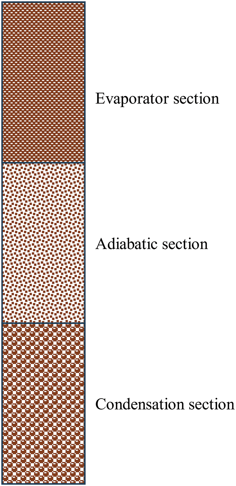
Figure 1: Structure diagram of gradient structure wick
When the liquid working medium climbs up along the wick, the inertial effect is small for the capillary structure with a small effective pore size (<300 μm for water). The rise of the liquid is mainly affected by the balance between capillary pressure, viscous resistance, and gravity. For any moment, it can be expressed as the following equilibrium equation:
where h is the rising height of the liquid climbing along the wick, dh/dt is the capillary rising velocity, and g is the acceleration of gravity.
In order to obtain the functional relationship of reff in terms of θ, this paper fits the data from the previous numerical solution of capillary pressure in tightly packed spheres [27]. The following results are obtained by data fitting:
By combining Eqs. (8) and (9), we can get:
In order to make the liquid medium rise to the highest hmax, it is necessary to meet dh/dt ≥ 0, so as to obtain:
On the premise of ensuring the capillary pressure, the permeability should be increased as much as possible to improve the capillary performance of the wick. For granular porous structures, Blake-Kozeny proposed a permeability prediction formula [28]:
Although the prediction results of the Blake-Kozeny formula are not accurate for granular wicks, they can be used to predict the trend change: the permeability increases with the increase of particle diameter. Therefore, when the particle size of the sintered stainless steel wick is segmented as follows by the Eq. (12), it can not only ensure the continuous flow of the liquid along the wick climbing process but also make the wick have the maximum permeability. At this time, the gradient structure wick has the best capillary performance.
Since the experiment was carried out at 25°C, the working fluid surface tension coefficient at 25°C was σ = 0.07197 N/m, and the density of water was ρ = 997.0 kg/m3. In this paper, the size of the wick is 90 mm × 40 mm × 1.0 mm. The specific parameters are brought into Eq. (13).
In this study, spherical 316 L stainless steel powder was the material for the processing of the wick sample. The average powder sizes selected are 36–42, 71–78, and 106–112 μm. Therefore, the stainless steel powder particle size d1 is 40 μm, d2 is 75 μm, and d3 is 110 μm. All of them are the average particle diameter. The manufacturing process of single-structure wick includes three main steps:
(1) The stainless steel powder is carefully poured into the customized mold. Subsequently, it is placed on the vibration platform to ensure uniform distribution for utilization in the high-temperature sintering process.
(2) Stainless steel powders are typically sintered within the temperature range of 1000°C to 1300°C. Some researchers [29,30] have put forward that the optimal sintering temperature lies between 1150°C and 1200°C. Consequently, a sintering temperature of 1200°C was selected in this study. The sintering time was set at one hour.
(3) After the completion of the sintering process, cooling the porous sintered wick with air inside the furnace until the temperature is lower than 100°C. Finally, the mold is disassembled to obtain the requisite wick structure.
The manufacturing process of the gradient structure wick differs from that of the single structure wick in the initial step. Firstly, fill a certain length of stainless steel powder into the mold. Subsequently, stainless steel powder of different particle sizes is filled based on previously filled stainless steel powder. Vibration is applied to ensure good contact between the layers and to guarantee that the stainless steel powders of different sections have the same width and thickness in the filling process. After the filling is completed, the subsequent steps are identical to those of the single structure. The finished product of the wick made of stainless steel powder is shown in Fig. 2. And the scanning electron microscopy (SEM) images of three different sizes of wicks are shown in Fig. 3 [29]. It can be observed that with the increase in particle size, the pore size increases significantly and the permeability increases significantly. The detailed parameters of these four types of wick samples are listed in Table 1.

Figure 2: Stainless steel powder wick sample

Figure 3: SEM images of sintered stainless steel wicks with different sizes

As the stainless steel powder wick is exposed to air, its surface is prone to be contaminated by dust, oil film, and other substances, which may have an adverse impact on the test results. Hence, it is necessary to clean the stainless steel powder wick. In this study, the samples were initially cleaned using ethanol for 10 min. Subsequently, they were washed with deionized water in an ultrasonic cleaner and then dried in a vacuum oven.
3.2 Permeability Test Experiment
At present, most of the tests on the permeability of powder-sintered porous wicks use the forced fluid flow method proposed by Adkins and Dykhuizen [31] based on Darcy laminar flow. Therefore, this study uses this method to test the permeability of wick samples.
The experimental system of the permeability of the wick is shown in Fig. 4. The medium is deionized water, which is driven by a low-power gear pump (AT-305S) ensuring smooth and continuous flow. The Y-filter (SY11C-H10) is added to prevent the fine solid impurities in the water from entering the wick sample to block the pores and increase the resistance. The valve (WL91H-320P) with an adjustable flow rate is controlled to adjust the flow rate of deionized water so that the experimental conditions are more consistent with the operating conditions of the heat pipe. The inlet and outlet pressures of the test section were measured by two digital pressure sensors (SLDYB-801D/C, 0–100 kPa, 0.25%FS). The Coriolis mass flowmeter (accuracy 0.1 level) is used to control and measure the mass flow rate of the medium flowing through the wick sample, and the mass flow rate of the liquid working medium through various wick samples under steady state is further calculated and recorded. During the experimental process, once the flow attains a steady state, the flow rate is gauged over a period of 2 min. To guarantee the stability and consistency of the flow rate measurement, three consecutive flow rate measurements are carried out for each individual test. Subsequently, the flow rate is computed as the average value of these measured flow rates. It should be noted that the room temperature was maintained at 25°C ± 0.1°C throughout the entire experiment.

Figure 4: Permeability test experimental system
3.3 Capillary Rise Test Experiment
In this study, the wick sample (sintered stainless steel powder) and the liquid medium (deionized water) have different emissivity characteristics at 25°C. The infrared thermal imager is used to obtain the image with an obvious color difference, and then the accurate capillary rise height is obtained.
The capillary rise test system includes an infrared thermal imager (SPARK M80hd, Canada), data acquisition computer, iron stand, small lifting platform, working medium container, sample fixing device, and glass cover, as shown in Fig. 5.

Figure 5: Capillary rise test experimental system
The wick sample was vertically fixed in the fixture of the iron shelf, and the container placed on the lifting platform was filled with deionized water. The lifting platform was adjusted to make the sample vertically immersed in the deionized water of the container, and the immersion depth was about 3 mm. The working medium overcomes its own gravity to climb up under the capillary pressure of the wick, and the climbing process is recorded by an infrared thermal imager. When it comes to the subsequent data processing, the evaporation of the working medium during the capillary climbing process can be overlooked. Because the complete experiment is carried out in a closed space which is composed of organic glass and kept at 25°C ± 0.1°C. Such conditions make the test space nearly saturated with water vapor and cut down on the evaporation loss of the working medium during the capillary climbing process.
According to the infrared thermal imager, the image of different capillary rise height at each moment can be obtained. As shown in Fig. 6, the rectangular Rect 1 is established with half of the length of the bottom side of the wick sample as wide and the right side as long, and the rectangular Rect 2 is also established with half length of the wick sample bottom side as wide and the capillary rise height as long. Owing to the significant color disparity between the infrared thermal image of the sample and that of the working fluid, the determination of the height of the curved liquid surface becomes rather facile, which in turn facilitates the establishment of the rectangular Rect 2. Given that the length of the wick sample is L, the rise height H of the curved surface along which the working fluid ascends within the wick can be computed using Eq. (13).

Figure 6: Schematic diagram of the method to determine the capillary rising height
The uncertainty of the calculated parameters is calculated according to the formula of Moffat R J [32]:
where δR is the uncertainty of parameter R, Vi is the independent variable of parameter R, and δVi is the uncertainty of independent variable Vi. The measurement uncertainty of infrared thermal imager can be calculated by the following formula:
Through calculation, the uncertainty of permeability is ±1.57%, and the uncertainty of capillary rise height is 3.09%, which are within the allowable range of error.
4.1 Effect of Stainless Steel Powder Size on the Wick Porosity
The three wick samples with varying particle dimensions underwent sintering using the same procedure, and the porosity of each sample was measured. The average porosity of all samples was used in the study to reduce the influence of random error on the experimental results. As shown in Fig. 7, for the traditional single particle size wick, the porosity of the wick increases with the increase of the stainless steel particle size from 40 to 110 μm. This is consistent with the trend predicted by the Blake-Kozeny formula mentioned above and the literature [24]. This is because the large-grained stainless steel powder is more likely to form a loose stacking structure, and it is also easy to form more channels and pores during the sintering process, thereby increasing the overall porosity.

Figure 7: Variation of the porosity of wick with different powder size
For the gradient structure wick designed in this paper, its porosity is only inferior to that of the 110 μm particle size wick and is significantly improved compared with the porosity of 40 and 75 μm particle size wick. This is mainly because the gradient structure wick undergoes segmented sintering, and the particles in each section do not interfere with one another. Only the phenomenon of small particle size filling large particle size at the interface occurs, which has little impact on the overall porosity of the wick. Therefore, to a certain extent, the gradient structure wick can enhance the porosity of the wick.
4.2 Effect of Stainless Steel Powder Size on the Wick Permeability
In this section, the pressure drop of the medium at different flow rates was measured and analyzed. As shown in Fig. 8, the medium pressure drop grows as the flow rate increases. By linearly fitting the pressure drop curve and ignoring the error of individual data in the experiment, the slope of the ∆p-Q linear fitting line (equal to μlL/(KA)) is obtained, and the permeability of the wick samples is calculated. As is also observable in Fig. 8, in the case of the single sintered stainless steel powder wick, the gradient of the pressure drop curve declines remarkably when the powder particle size escalates from 40 to 110 μm. The reason for this phenomenon lies in the fact that as the powder particle size enlarges, the pores expand, which consequently brings about an augmentation in the flow area. Therefore, the flow resistance of the larger particle-size powder sintered wick sample is reduced, and the pressure drop on both sides is small. The pressure drop of the gradient structure wick designed in this paper is only greater than that of the 110 μm particle powder wick, which is significantly lower than that of the 75 μm particle powder wick and 40 μm particle size wick. The smaller the pressure drop is, the smaller the resistance of the wick is. The gradient structure wick can promote the backflow of the heat pipe working medium.

Figure 8: Variation of the pressure drop at different medium flow rate
The permeability of sintered samples with different particle sizes was calculated according to the slope of the ∆p-Q fitting line, and the results are shown in Fig. 9. It is evident that, with regard to the conventional wick with a single particle size, the permeability experiences an upward trend as the average particle size of the stainless steel powder rises within the range from 40 to 110 μm. This is because stainless steel powder of larger particle sizes forms relatively large pores. These larger pores can accommodate more liquid and enable liquid to pass through more easily, thus enhancing air permeability. Furthermore, stainless steel powder possessing larger particle dimensions exhibits a reduced surface area, given that the surface area is inversely related to the square of the particle diameter. Consequently, powder with larger particle sizes will reduce the surface tension effect, facilitate liquid penetration, and increase permeability.

Figure 9: Variation of the sintered stainless steel powder wick permeability with different particle size
For the gradient structure wick designed in this paper, its permeability lies between that of the two single-size wicks, 75 μm particle powder wick and 110 μm particle size wick. This is mainly because, in the gradient structure wick, smaller particles can attract and retain more liquid. At the same time, larger particles are more conducive to the passage of liquid. Moreover, the liquid in the wick can penetrate and disperse more evenly. To a certain extent, this can enhance the permeability of the wick.
4.3 Effect of Stainless Steel Powder Size on Wick Capillary Pressure
Fig. 10 presents the infrared thermal imaging of the capillary rise phenomenon of the sintered stainless steel powder wicks with particle sizes of 40, 75, and 110 μm, as well as the gradient particle size structure. In the same ambient room temperature environment, owing to the disparity in emissivity between the working fluid water and the sintered stainless steel, the areas where the working fluid ascends within the wick are manifested as dark blue, allowing for the visualization of the capillary rise height of the medium in the wick. When the wick sample comes into contact with deionized water, under the impetus of the capillary pressure within the wick, the deionized water is capable of ascending against the force of gravity within the wick’s flow channels. As can be discerned from the diagram, during the initial stage, the curved liquid surface within the wick experiences a relatively rapid upward movement. However, as the height of the curved liquid surface augments, the rate of climbing gradually diminishes.

Figure 10: Variation of the sintered stainless steel powder wick permeability with different particle size
Fig. 11 shows the relationship between the capillary climbing height and time of sintered stainless steel powder wicks with particle sizes of 40, 75, 110 μm, and gradient structure. It can be observed from the diagram that the capillary climbing speeds of different wicks vary. In the initial stage, the capillary climbing speed is relatively large. This can be attributed to the fact that during the initial phase of capillary climbing, the hydrostatic pressure induced by gravity is relatively insignificant. In the subsequent stage, as the influence of gravity intensifies, the rate of capillary climbing progressively decelerates. With the passage of time, the disparities in capillary rise heights among the tested samples tend to become more pronounced. In the case of a single-structure wick, the capillary rise velocity and height do not exhibit a monotonous variation with the augmentation of powder particle size, a phenomenon that is in concordance with what was observed in literature [25]. This may be due to the tiny pores created between the different particles lead to discrepancies with the theory. Among them, the 75 μm wick has the fastest climbing speed and the highest climbing height, while the 40 μm wick is the slowest and has the lowest climbing height. For the gradient structure wick, within 28 s, its climbing speed is similar to that of the 75 μm wick and the 110 μm wick. However, subsequently, they exhibit different climbing speeds. The relationship of capillary climbing speed is: GSW > SSW2 > SSW3 > SSW1.

Figure 11: Capillary climbing height of sintered wicks with different particle size and gradient particle size structures
4.4 Effect of Stainless Steel Powder Size on the Wick Capillary Performance Parameter
For the single particle size structure wick, as the powder particle size increases, the capillary rise height and rate of the powder-sintered porous structure do not increase monotonously. Instead, they reach the maximum when the particle size is 75 μm. Compared with the 110 μm powder particle size wick, the 40 μm powder particle size structure has a smaller pore size and a higher capillary pressure. However, the comprehensive capillary performance of the 40 μm wick is inferior to that of the 110 μm wick because the permeability of the 40 μm wick is too low to offset the influence of capillary pressure. The pore size and permeability of the 75 μm wick are in an intermediate state. Moreover, its capillary pressure ∆pcap is significantly larger than that of the other two porous structures. Due to the combined effect of capillary pressure and permeability, the 75 μm wick and the 110 μm wick have good and similar capillary performance parameters.
For the gradient particle size structure wick, as can be seen from Table 2, the GSW wick is sintered by three different sizes of stainless steel particles, namely 40, 75, and 110 μm. The average pore size of the GSW wick is similar to that of the 75 μm wick. The capillary pressure of the GSW wick is higher than that of 40 μm, 75 μm wick, and 110 μm. The permeability of the GSW wick is slightly worse than the 110 μm wick but better than that of 40 and 75 μm. Therefore, the capillary performance of the gradient particle size structure wick GSW is equivalent to a combination of the advantages of large particle size powder and small particle size powder. It has higher permeability, larger capillary pressure, and the best capillary performance. Compared with the 75 μm wick with the same average particle size, its capillary performance parameter is improved by more than 30%.

This paper focuses on the transport characteristics of sintered powder wicks within flat heat pipes and undertakes an in-depth exploration of them. By means of theoretical analysis, an axial gradient structure wick is devised. The porosity, permeability, and capillary climbing height of the wick are experimentally determined. The relationship between the powder particle size and the effective capillary radius is employed to compute the capillary force and the capillary performance factor of the wick, followed by an analysis of the comprehensive capillary performance of each wick. The principal conclusions are as follows:
1. In this study, sintered stainless steel powder is used as the wick material. The particle size distribution of the optimal axial gradient structure wick (average particle diameter values: 40 μm for the evaporation section, 75 μm for the adiabatic section, and 110 μm for the condensation section) is derived, and the transport capacity of the gradient structure wick under limited scale is optimized.
2. With the augmentation of the particle size of stainless steel powder, the porosity of the wick exhibits an upward trend. To a certain extent, the gradient structure wick is capable of effectively augmenting the porosity of the wick. The permeability of the sintered wick fluctuates in accordance with the powder particle size. The sample with a particle size of 110 μm, which is larger, demonstrates the greatest permeability. The permeability of the GSW sample is only inferior to that of the SSW3 sample and it also possesses favorable permeability.
3. Compared with the traditional single-structure wick, the capillary performance parameter of the gradient structure wick is improved by more than 30%. From this perspective, the gradient structure wick designed in this paper can significantly improve the capillary limit of the wick and provide a good alternative for the wick of two-phase heat exchange devices.
Acknowledgement: Not applicable.
Funding Statement: The authors received no specific funding for this study.
Author Contributions: Shenghua Li: Writing—original draft, Validation, Software, Methodology, Investigation. Kehan Liu: Writing, Investigation. Bangxing Qian: Validation, Supervision, Investigation. Ziwei Wen: Validation, Supervision, Investigation. Bo Shi: Writing—review & editing, Supervision, Methodology. All authors reviewed the results and approved the final version of the manuscript.
Availability of Data and Materials: The data that support the findings of this study are available from the corresponding author upon reasonable request.
Ethics Approval: Not applicable.
Conflicts of Interest: The authors declare no conflicts of interest to report regarding the present study.
References
1. Liu T, Dunham MT, Jung KW, Chen B, Asheghi M, Goodson KE. Characterization and thermal modeling of a miniature silicon vapor chamber for die-level heat redistribution. Int J Heat Mass Transf. 2020;152:119569. [Google Scholar]
2. Garimella SV. Advances in mesoscale thermal management technologies for microelectronics. Microelectron J. 2006;37(11):1165–85. [Google Scholar]
3. Jiang H, Wang X, Ding C, Shan D, Guo B, Qi H, et al. A review of emerging design and theoretical progress on vapor chamber for efficient thermal performance. Int J Heat Mass Transf. 2024;231:125814. [Google Scholar]
4. Xie Y, Yang X, Li X, Liu S, Zhang P. Review of heat pipe technology in the field of aviation. Cooling Air Cond. 2023;5:613–24. [Google Scholar]
5. Rakshith BL, Asirvatham LG, Angeline AA, Manova S, Bose JR, Selvin Raj JP, et al. Cooling of high heat flux miniaturized electronic devices using thermal ground plane: an overview. Renew Sustain Energ Rev. 2022;170:112956. [Google Scholar]
6. Boubaker R, Lorgouilloux Y, Ouenzerfi S, Harmand S. Experimental study of a bilayer ceramic wick for the evaporator of a two-phase heat transfer device. Int J Heat Mass Transf. 2024;228:125609. doi:10.1016/j.ijheatmasstransfer.2024.125609. [Google Scholar] [CrossRef]
7. Yeh C, Chen C, Chen Y. Heat transfer analysis of a loop heat pipe with biporous wicks. Int J Heat Mass Transf. 2009;52(19–20):4426–34. doi:10.1016/j.ijheatmasstransfer.2009.03.059. [Google Scholar] [CrossRef]
8. Singh R, Akbarzadeh A, Mochizuki M. Effect of wick characteristics on the thermal performance of the miniature loop heat pipe. J Heat Transf. 2009;131(8):082601. doi:10.1115/1.3109994. [Google Scholar] [CrossRef]
9. Hwang G, Kaviany M, Anderson WG, Zuo J. Modulated wick heat pipe. Int J Heat Mass Transf. 2007;50(7/8):1420–34. doi:10.1016/j.ijheatmasstransfer.2006.09.019. [Google Scholar] [CrossRef]
10. Mooney JP, Walsh PA, Punch J, Egan V. A capillary flow model for discretely graded porous media in two phase heat transfer applications. Int J Thermofluids. 2022;15(11):100183. doi:10.1016/j.ijft.2022.100183. [Google Scholar] [CrossRef]
11. Wang D, Liu Z, He S, Yang J, Liu W. Operational characteristics of a loop heat pipe with a flat evaporator and two primary biporous wicks. Int J Heat Mass Transf. 2015;89:33–41. doi:10.1016/j.ijheatmasstransfer.2015.05.042. [Google Scholar] [CrossRef]
12. Wu S, Wang D, Chen Y. Investigating the effect of double-layer wick thickness ratio on heat transfer performance of loop heat pipe. Int J Therm Sci. 2014;86(1):292–8. doi:10.1016/j.ijthermalsci.2014.07.014. [Google Scholar] [CrossRef]
13. Semenic T, Catton I. Experimental study of biporous wicks for high heat flux applications. Int J Heat Mass Transf. 2009;52(21–22):5113–21. doi:10.1016/j.ijheatmasstransfer.2009.05.005. [Google Scholar] [CrossRef]
14. Semenic T, Lin YY, Catton I, Sarraf DB. Use of biporous wicks to remove high heat fluxes. Appl Therm Eng. 2008;28(4):278–83. doi:10.1016/j.applthermaleng.2006.02.030. [Google Scholar] [CrossRef]
15. Wang J, Catton I. Enhanced evaporation heat transfer in triangular grooves covered with a thin fine porous layer. Appl Therm Eng. 2001;21(17):1721–37. doi:10.1016/S1359-4311(01)00044-8. [Google Scholar] [CrossRef]
16. Li Y, Chen C, Zeng Z. Experimental investigation into heat transfer performance of micro heat pipe with fiber-composite grooved wick. J South China Univ Tech. 2013;41(7):45–9. [Google Scholar]
17. Xu J, Zou Y. Research progress of capillary structure of loop heat pipe. Chin J Electr Eng. 2013;8:65–73. [Google Scholar]
18. Xu J, Zou Y, Cheng L. Pore structure optimization and performance study of loop heat pipe composite wick. Chin J Electr Eng. 2012;23:70–4. [Google Scholar]
19. Tang Y, Deng D, Lu L, Pan M, Wang Q. Experimental investigation on capillary force of composite wick structure by IR thermal imaging camera. Exp Therm Fluid Sci. 2010;34(2):190–6. doi:10.1016/j.expthermflusci.2009.10.016. [Google Scholar] [CrossRef]
20. Tang Y, Deng D, Huang G, Wan Z, Lu L. Effect of fabrication parameters on capillary performance of composite wicks for two-phase heat transfer devices. Energy Convers Manag. 2013;66:66–76. doi:10.1016/j.enconman.2012.09.027. [Google Scholar] [CrossRef]
21. Li Y, He H, Zeng Z. Evaporation and condensation heat transfer in a heat pipe with a sintered-grooved composite wick. Appl Therm Eng. 2013;50(1):342–51. doi:10.1016/j.applthermaleng.2012.07.042. [Google Scholar] [CrossRef]
22. Ma Y, Zhang Y, Yu H, Su GH, Huang S, Deng J, et al. Capillary evaporating film model for a screen-wick heat pipe. Appl Therm Eng. 2023;225:120155. [Google Scholar]
23. Ma Y, Zhang Y, Yu H, Huang J, Zhang S, Wang X, et al. Numerical modeling of alkali metal heat pipes. Ann Nucl Energy. 2025;210:110855. doi:10.1016/j.anucene.2024.110855. [Google Scholar] [CrossRef]
24. Zhao Z, Peng G, Zhang Y, Zhang D. Heat transfer performance of flat micro-heat pipe with sintered multi-size copper powder wick. Case Stud Therm Eng. 2023;42:102720. doi:10.1016/j.csite.2023.102720. [Google Scholar] [CrossRef]
25. Deng D, Tang Y, Huang G, Lu L, Yuan D. Characterization of capillary performance of composite wicks for two-phase heat transfer devices. Int J Heat Mass Transf. 2013;56(1–2):283–93. doi:10.1016/j.ijheatmasstransfer.2012.09.002. [Google Scholar] [CrossRef]
26. Ma Y, Huang C, Wang X. Experimental investigation on boiling heat transfer enhanced by gradient aperture porous copper. Appl Therm Eng. 2021;191:116877. doi:10.1016/j.applthermaleng.2021.116877. [Google Scholar] [CrossRef]
27. Zhu X. The influence and mechanism of porous media on atomization/evaporation of liquid fuel in thermal environment. Hangzhou, China: Zhejiang University; 2023. [Google Scholar]
28. Pacella HE, Eash HJ, Federspiel WJ. Darcy permeability of hollow fiber bundles used in blood 503 oxygenation devices. J Memb Sci. 2011;382(1–2):238–42. doi:10.1016/j.memsci.2011.08.012. [Google Scholar] [PubMed] [CrossRef]
29. Chen C. Fabrication and heat transfer performance of stainless steel heat pipe by powder sintering. Guangzhou, China: South China University of Technology; 2018. [Google Scholar]
30. Yang D, Lu X, Cao W. Investigation of single-flow resistance in sintered stainless steel particles porous media. Mach Des Manuf. 2014;(1):197–200. [Google Scholar]
31. Peterson GP. An introduction to heat pipes. In: Modeling, testing, and applications. 1st ed. Wiley-Interscience; 1994 Sep 28. [Google Scholar]
32. Moffat RJ. Describing the uncertainties in experimental results. Exp Therm Fluid Sci. 1988;1(1):3–17. doi:10.1016/0894-1777(88)90043-X. [Google Scholar] [CrossRef]
Cite This Article
 Copyright © 2025 The Author(s). Published by Tech Science Press.
This work is licensed under a Creative Commons Attribution 4.0 International License , which permits unrestricted use, distribution, and reproduction in any medium, provided the original work is properly cited.
 Downloads
 Citation Tools