
 Submit a Paper
 Propose a Special lssue
 Open Access
ARTICLE

Heat Transfer Characterization of TPMS Heat Exchangers Applied to the Aerospace Field
1 School of Civil Engineering, Luoyang Institute of Science and Technology, Luoyang, 471023, China
2 Henan Key Laboratory of Green Building Materials Manufacturing and Intelligent Equipment, Luoyang, 471023, China
3 Xi’an Special Equipment Inspection Institute, Xi’an, 710065, China
4 Institute for Advanced Technology, Shandong University, Jinan, 250061, China
5 National Key Laboratory of Nuclear Reactor Technology, Nuclear Power Institute of China, Chengdu, 610004, China
6 School of Resources Engineering, Xi’an University of Architecture and Technology, Xi’an, 710055, China
* Corresponding Authors: Mu Du. Email: ; Mingyang Yang. Email:
(This article belongs to the Special Issue: Microscale Heat and Mass Transfer and Efficient Energy Conversion)
Frontiers in Heat and Mass Transfer 2025, 23(2), 601-614. https://doi.org/10.32604/fhmt.2025.061192
Received 19 November 2024; Accepted 27 January 2025; Issue published 25 April 2025
 View Full Text
 Download PDF
Abstract
In exploring hypersonic propulsion, precooler combined engines require the development of lightweight, efficient, and compact heat exchangers (HX). As additive manufacturing technology continues to progress, triply periodic minimal surface (TPMS) structures, characterized by exceptionally high surface area to volume ratios and intricate geometric structures, have demonstrated superior heat transfer performance. This research examines the thermal-hydraulic (TH) behavior of FKS and Diamond as heat transfer structures under different Reynolds numbers through numerical simulations. The Nusselt number for FKS is 13.2%–17.6% higher than Diamond, while the friction factor for FKS is approximately 18.8%–29.3% higher. A detailed analysis of the internal flow mechanisms reveals that the flow pattern within TPMS can be summarized as cyclic convergence-separation-convergence. The fluid experiences constant disturbances from the structure in all spatial directions, generating strong turbulent mixing and large wall shear stresses, which significantly enhance heat transfer performance.Keywords
Nomenclature
| AS | Surface area (m2) |
| Aeff | Effective surface area of TPMS (m2) |
| cp | Specific heat (J·kg−1·K−1) |
| De | Hydraulic diameter (m) |
| f | Fanning friction factor |
| H | Specific enthalpy of fluid (J·kg−1) |
| h | Convective heat transfer coefficient (W·m−2·K−1) |
| k | Turbulent kinetic energy (m2·s−2) |
| L | Length corresponding to differential pressure (m) |
| p | Pressure (Pa) |
| Pk | Shear production of turbulent |
| Pωb | Buoyancy production terms |
| F1 | Non-dimensional blending function |
| q | Heat flux (W·m−2) |
| T | Temperature (K) |
| v | Velocity (m·s−1) |
| V | Volume of fluid domain (m3) |
| x, y, z | Three dimensional coordinates (m) |
| y+ | Dimensionless wall distance |
| Greek Symbols | |
| λ | Thermal conductivity (W·m−1·K−1) |
| μ | Dynamic viscosity (Pa·s) |
| μt | Turbulent eddy viscosity (Pa·s) |
| ρ | Density (kg·m−3) |
| ω | Specific turbulence dissipation rate (s−1) |
| Subscripts | |
| c | Cold channel |
| f | Fluid |
| h | Hot channel |
| w | Wall |
| Abbreviations | |
| HT | Heat transfer |
| HX | Heat exchangers |
| SST | Shear Stress Transport |
| TH | Thermal-hydraulic |
| TPMS | Triply periodic minimal surface |
In hypersonic propulsion research, the precooler engine has become a typical representative of combined propulsion innovation [1]. Precooling is an advanced technology that rapidly cools high-temperature incoming air to the allowable temperature of the engine compressor using specific methods [2]. The application of precooling technology offers numerous benefits: lowering the intake air temperature improves the thermal environment of engine components, alleviates thermal protection issues caused by high-speed stagnation heat, and extends the cruise range of hypersonic vehicles. Lower intake temperatures can also increase the mass flow rate of the intake air, thereby enhancing the engine thrust generated by the heat released during combustion. Precooling technology is at the core of the precooling air-breathing combined engine, and the lightweight, efficient precooler HX is key to this technology [3–5]. The characteristic of a precooler engine is that the fuel directly cools the incoming high-temperature air through the precooler. Considering the complex operational environment of the precooler engine, the precooler HX needs to meet design requirements and must also feature high compactness, resistance to elevated temperatures and pressures, and ensure safety and reliability [6].
In light of the advancement of additive manufacturing technology, TPMS structures with high porosity can significantly increase the internal heat transfer (HT) area, making them an ideal choice for HX designs. The following characteristics of TPMS structures make them highly promising for next-generation HX designs [7–10]: 1) TPMS separates a 3D space into two regions with high surface area, each independent from the other [11]; 2) The average curvature at any point on a TPMS is zero, and each separated channel is interconnected in all directions. Therefore, fluid flow can move freely in any direction, and the flow resistance in TPMS may be lower [12]; 3) TPMS can generate complex flow patterns, which enhance HT efficiency, prevent scaling, and reduce the possibility of blockages; 4) The formation of TPMS is the direct result of natural force distribution, and its potential energy is naturally minimized, offering excellent mechanical properties; 5) TPMS is controlled by simple implicit functions, and the parametric design of HX based on TPMS structures is straightforward; 6) TPMS is a self-supporting structure with good printability, ensuring the stability of the channel structures during the additive manufacturing process [13]. These characteristics suggest that TPMS structures are highly beneficial for HX design. TPMS precoolers can be 3D printed in a single step, with self-supporting capabilities, eliminating issues such as structural assembly, component welding, tube bundle leakage, and clogging that are common in traditional precooler manufacturing processes. Additionally, TPMS precoolers can precisely control the internal structure of the TPMS through mathematical equations. The continuous internal surface structure helps reduce the resistance to fluid flow, making the TPMS structure suitable for applications in aerospace under high-pressure conditions [14].
Researchers have studied the HT performance of different types of TPMS. Qureshi et al. [15–18] applied three TPMS structures (Primitive, Gyroid, Diamond) to finned metal foam-phase change material systems. By comparing the thermal conductivity performance of these TPMS structures with traditional metal foams, they found that all TPMS structures shortened the phase change material’s melting time and enhanced the average HT coefficient. Fan et al. [19,20] proposed a novel sheet-like structure based on TPMS. The thermal performance of the battery thermal management system was studied through simulations and experiments. The study showed that incorporating TPMS heat exchange structures led to a 9.0% reduction in the maximum temperature and a 59.8% decrease in the temperature difference of the sheet-like battery module. Kaur et al. [21] completed a research on the TH characteristics of two TPMS surfaces (Gyroid-sheet and Primitive-sheet). The results showed that HX based on TPMS structures as the core performed better than those with random metal foam structures in the next generation of HX. Modrek et al. [22] designed TPMS-based heat exchangers using topology optimization techniques. Their research provided a reference for the topology customization and performance prediction of TPMS-based heat exchangers. Alteneiji et al. [23] used computational fluid dynamics (CFD) simulation methods to explore the HT efficiency of compact HX based on Gyroid and Primitive under different heat fluxes. They calculated parameters such as the HT efficiency, the number of HT units, and flow resistance for both structures.
In addition to comparing the HT performance of different TPMS structures as the core of HX, some researchers have optimized the HT performance of the TPMS structures themselves by altering factors such as wall thickness and unit size. Attarzadeh et al. [24] performed a computational study on the TPMS-structured HX, evaluating its thermal efficiency, heat transfer coefficient, and pressure drop across the channels. They revealed the potential relationships between design variables in the design process through laminar multi-objective optimization based on genetic algorithms. Wang et al. [25] proposed a TPMS based porous heat dissipation structure and optimization method. They utilized the TPMS functionality to establish a porous structure, inheriting the excellent comprehensive performance of TPMS. Based on the given constraints, they derived an optimized porous structure with periodic smoothness and variable wall thickness through problem transformation. Huang et al.’s [9] research shows that the TPMS regenerator exhibits an improvement in overall performance by 10.9%–32.5% compared to the PCHE regenerator. At the same time, with half the volume, the TPMS regenerator achieves approximately four times the power-to-weight ratio compared to the PCHE. Kwasi-Effah CC et al. [26] studied the heat transfer properties of G-Prime and FRD TPMS structures through both numerical simulations and experimental approaches. They discovered that G-Prime-2 and FRD exhibit excellent TH performance in heat transfer applications.
TPMS structures applied in heat exchange applications are characterized by the use of air and water as working fluids, with fluid channels having relatively large equivalent diameters [27,28]. There is limited research on the application of TPMS structures in hypersonic vehicles. Based on the technical requirements of the precooler heat exchanger (HX), TPMS HT structures should have the smallest possible equivalent diameter to enhance the HT performance and compactness of the HX [28,29]. This study focuses on the application of TPMS as a HT structure in the field of hypersonic vehicles, using CFD methods to conduct a numerical study of high-compact TPMS HT structures. The flow and heat transfer (FHT) performances of two TPMS structures as HX are analyzed, and the mechanisms of HT enhancement by TPMS structures are discussed. The research findings can provide valuable reference for the further application of compact TPMS HT structures in the aerospace field.
Currently, applications of TPMS in HT are gradually gaining momentum, with various research methods being employed. This paper presents a complete numerical simulation. First, the TPMS structure is constructed using MATLAB code [30]. Then, Ansys SpaceClaim is used for preprocessing [31]. Next, the repaired structure is imported into ICEM for mesh discretization. After that, TH simulations are performed using Fluent software [32]. Finally, post-processing analysis is conducted using ANSYS CFD-Post software.
2.1 Tiply Periodic Minimal Surfaces
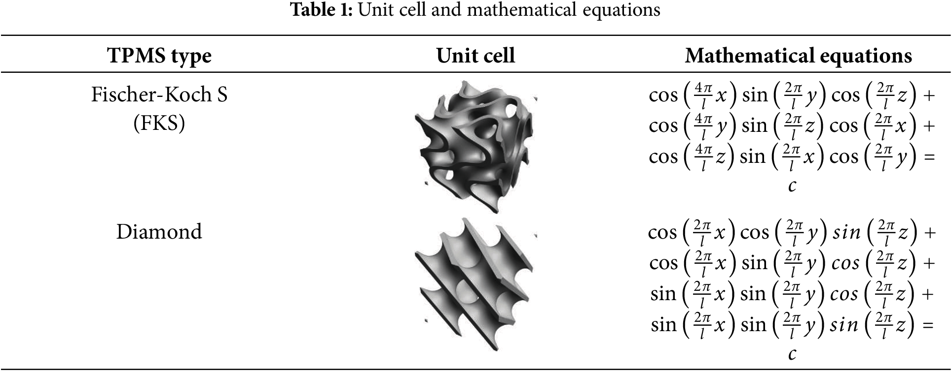
The level-set approximation equation involving trigonometric functions is used to describe the TPMS structure. The TPMS structure, mathematically speaking, is a set of continuous surfaces defined by implicit functions, created by arranging minimal surface units periodically along the x, y, and z directions. Below are the equations for two different TPMS structures. The equations and cell structures of TPMS (Fischer-Koch S and Diamond [33]) are listed in Table 1. Here, l is represented as the size of the unit cell. The value of c is used to describe the wall thickness and relative density of the TPMS solid. The TPMS divides the entire spatial domain into two separate subdomains, with the configuration of the TPMS structure being jointly influenced by the values of l and c.
This study investigates HX composed of FKS and Diamond. The overall computational model consists of three parts: 1) a solid phase region composed of TPMS; 2) a zone containing cold fluid; 3) a zone containing hot fluid. Helium at high temperature flows through the hot fluid channels, whereas hydrogen at low temperature moves in the opposite direction through the cold fluid channels. Two TPMS arrays form the solid phase region with a size of 4 mm × 4 mm × 24 mm, as shown in Fig. 1. For ensuring the development of flow components and suppress backflow, the fluid domains are extended by 10 mm at the inlet and outlet.
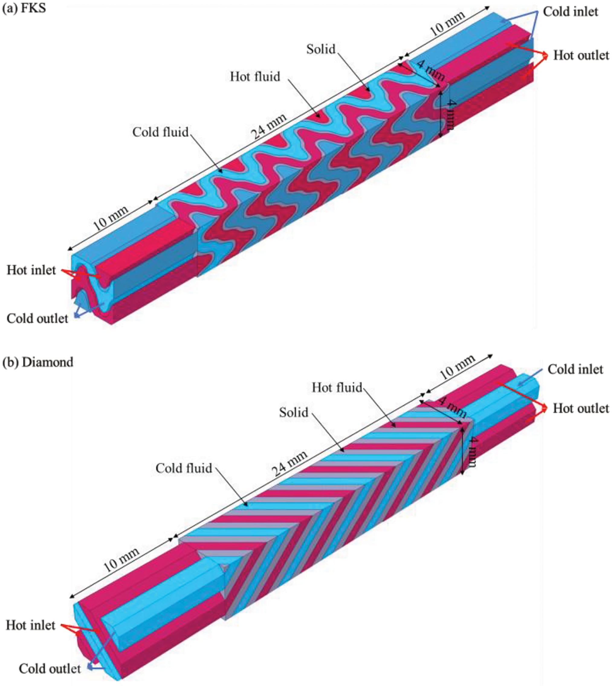
Figure 1: Geometric model of TPMS. (a) FKS, (b) Diamond
To make a consistent comparison of their FHT performance, the equivalent diameters of the two TPMS HXs are made identical. The HX composed of Diamond has a double-sided contact area of 624 mm2, a wall thickness of 0.66 mm, a porosity of 0.45, and an equivalent diameter of 1.1 mm. Similarly, the HX composed of FKS has a double-sided contact area of 1000 mm2, a wall thickness of 0.23 mm, a porosity of 0.7, and an equivalent diameter of 1.1 mm. The TPMS structure exhibits variations in its cross-sectional area and wetted perimeter along its length. Consequently, the equivalent diameter is calculated by the volume and area, as illustrated below:
2.3 Numerical Method and Governing Equations
The FHT process within the TPMS is simulated using ANSYS FLUENT. Based on the National Institute of Standards and Technology (NIST) database, the variation of fluid thermal properties is obtained, and the temperature-dependent thermal properties are fitted and embedded into FLUENT. For ensuring the accuracy of the simulation, the SST k-ω turbulence model is selected to better capture the turbulence within the TPMS structure. This turbulence model has been extensively validated in studies [34] and is suitable for forced convective HT problems under HX conditions. IN718 is selected as the TPMS material. The solver is chosen as the velocity-pressure coupling model, and the governing equations are discretized using the second-order upwind method. During the numerical simulation, the fluid inlet is set as a velocity inlet, the fluid outlet as a pressure outlet, and periodic boundary conditions are applied to the remaining boundaries. The hydrogen line pressure is set to 4 MPa, with an inlet velocity ranging from 2 to 28 m/s and the temperature is maintained at 283 K. The air line pressure is set to 0.3 MPa, with an inlet velocity ranging from 2 to 36 m/s and the temperature is maintained at 650 K. The calculation is considered complete when the residuals of the continuity and energy equations are less than 10−6.
The governing equations are shown below. All symbols are shown in Nomenclature.
Continuity equation:
Momentum equation:
Energy equation:
Turbulent kinetic energy equation:
Turbulent frequency equation:
F1 and F2 are defined as
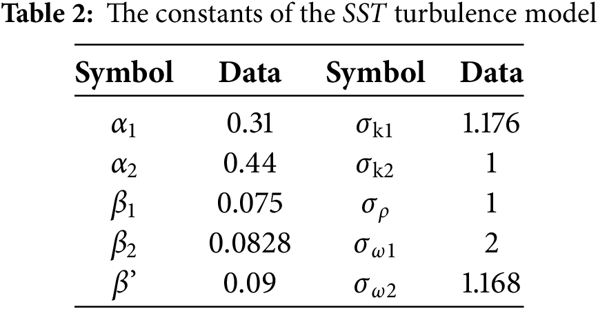
The constants in the equations are provided in Table 2 [32], and the remaining values can be determined by α = α1F1 + α2(1 − F1).
Solid heat conduction equation:
The Reynolds number is
The Prandtl number is
The local convective HT coefficient is calculated as
The average convective HT coefficient is defined as
The Nusselt is defined as
The Fan-ning friction factor formula is used for resistance calculation.
All symbols are shown in Nomenclature.
2.5 Model and Gird-Independent Verification
The TPMS structure has a unique geometric configuration. To ensure computational accuracy, the model is discretized using a hexahedral structured mesh. The SST k-ω turbulence model requires y+ < 1, so a smooth transition boundary layer with 12 layers and a growth rate of 1.2 is applied between the fluid and solid regions. At the same time, to reduce computational cost, the mesh density is appropriately decreased in regions far from the solid, as shown in Fig. 2.
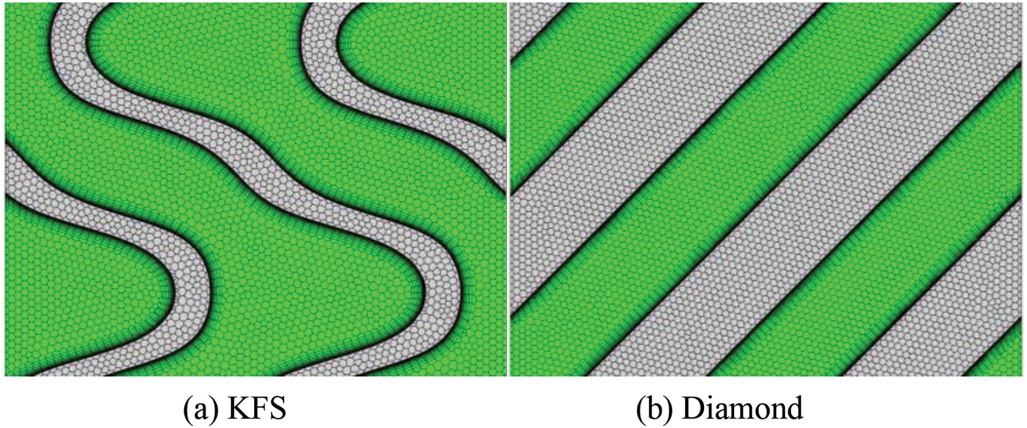
Figure 2: Gird details. (a) KFS, (b) Diamond
To examine the effect of grid independence on the FHT simulation results, four grid sizes are verified by calculating convergence time and the pressure drops, as shown in Fig. 3a. A grid size of 8.12 million is ultimately chosen for the simulation study to ensure both computational accuracy and efficiency. In addition, the numerical model is verified using the air thermal properties provided in the reference literature. The researchers conducted heat exchange experiments using water and air as the mediums for the diamond structure. To verify the reliability of the numerical model, we also used water and air for validation and compared the experimental data. The results show that the greatest difference between the simulated and experimental inlet-outlet temperature differences is 7.12%, with the simulation results falling within an acceptable range, as shown in Fig. 3b.
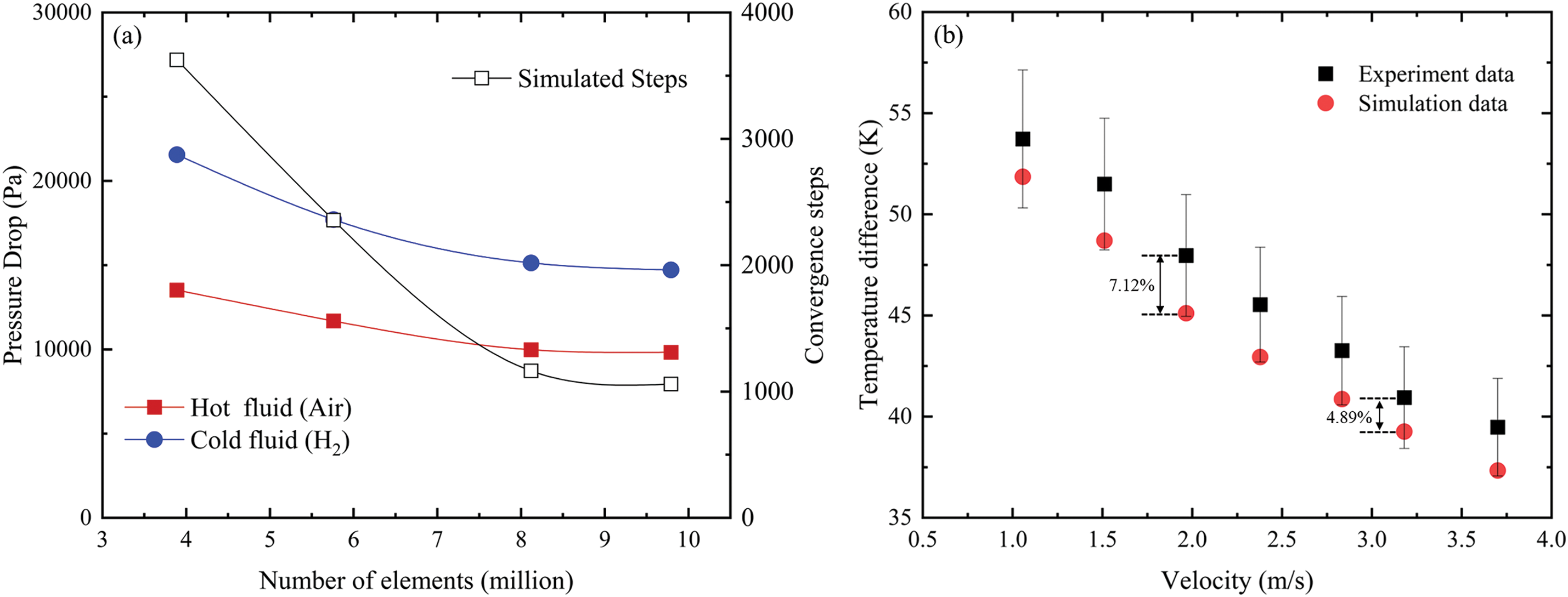
Figure 3: (a) Gird-independent verification with pressure drop and computational efficiency. (b) Verification of the numerical simulation and experimental data [35]
3.1 Flow and Heat Transfer Analysis of TPMS
Due to the different topological structures of TPMS, unique flow fields are generated when fluid passes through these structures. To study the FHT mechanisms of TPMS structures, the flow field distributions of the FKS and Diamond structures will be discussed, as shown in Figs. 4 and 5. The fluid converges at the junctions of multiple flow channels formed by the TPMS structure array and is then distributed into several channels with varying shapes, continuing to flow. The fluid undergoes a repetitive process of gathering and dispersing, and the flow pattern within the TPMS structure can be summarized as a cyclic flow of convergence-separation-convergence. This process fully utilizes the unique characteristics of the structure, enhancing its perturbation effect on the fluid.
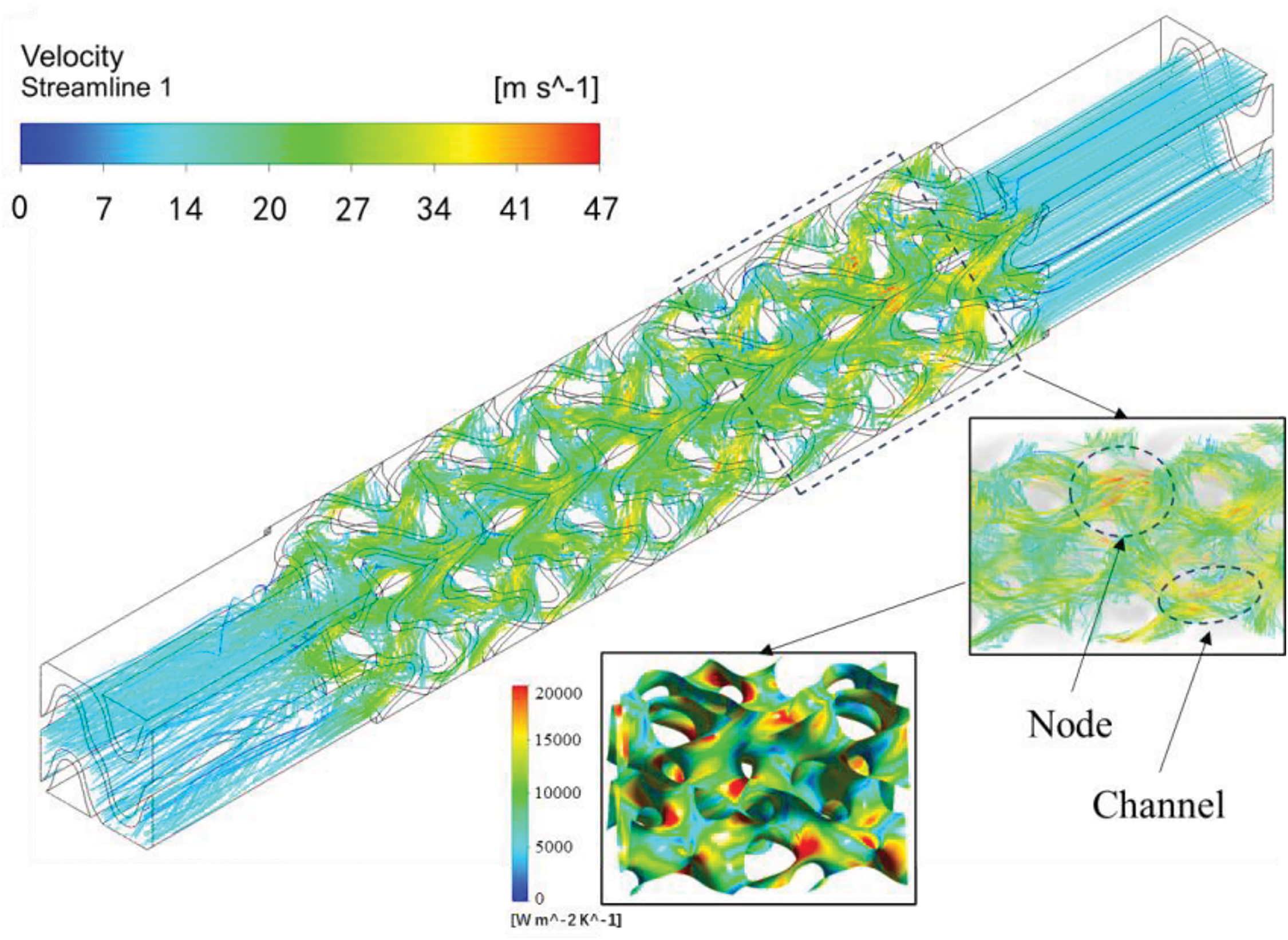
Figure 4: FHT distributions within the FKS structure
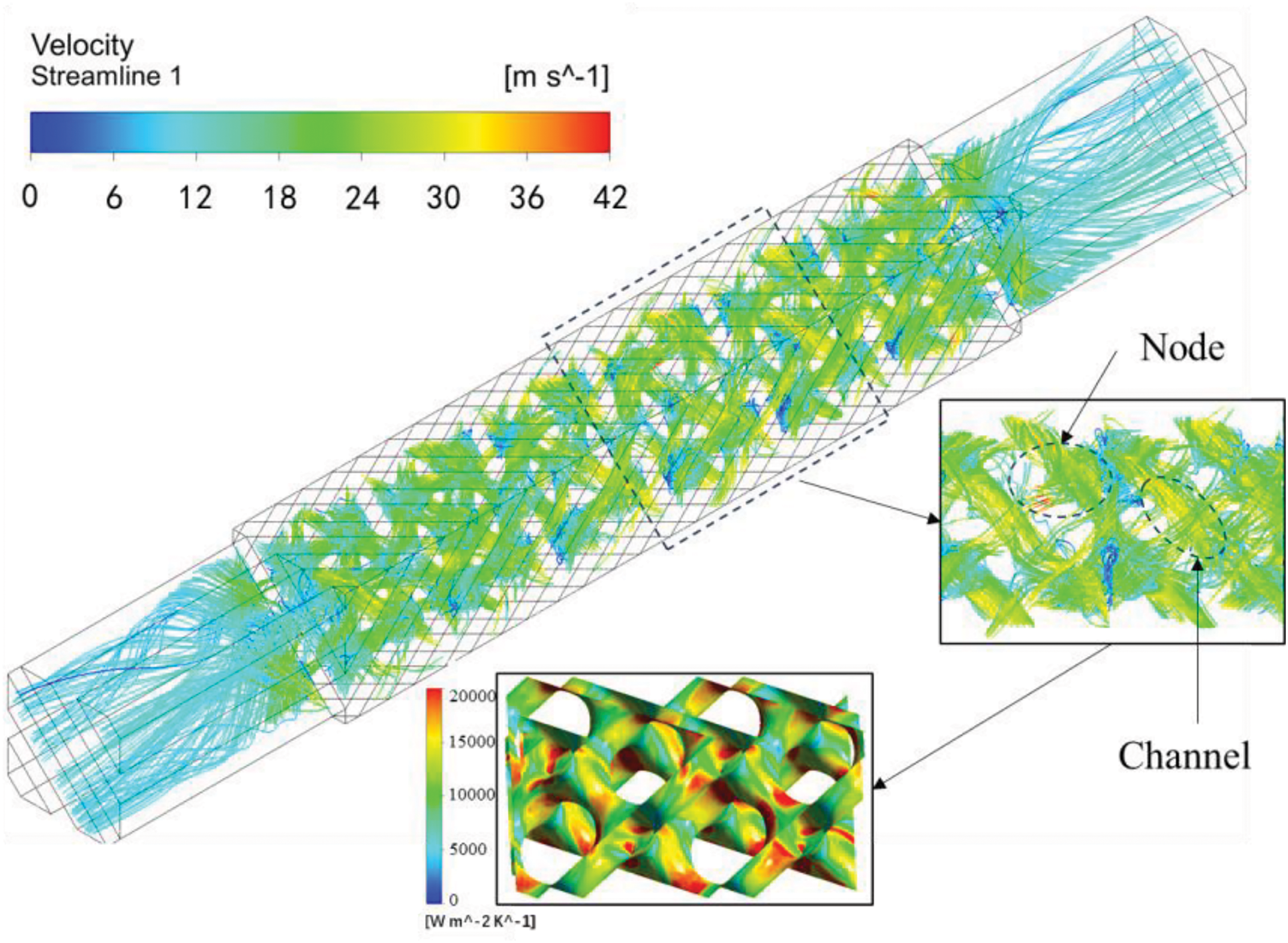
Figure 5: FHT distributions within the diamond structure
The flow details of the FKS structure are shown in Fig. 4. As the fluid flows along the winding channels, the streamlines exhibit a spiral motion. Local curvature variations within the channels cause changes in both the flow velocity and direction, resulting in complex, swirling flow. Meanwhile, portions of the fluid with relatively higher velocities shear against the FKS surface, enhancing HT in the regions where the fluid collides with the walls. The FHT distributions within the Diamond structure are shown in Fig. 5. Fluid from multiple channels converges at the junctions and is then distributed into several channels. During the flow process, the fluid is repeatedly redistributed and converged, enhancing fluid disturbance. Owing to the decrease in the cross-sectional area of the fluid channels at the junctions, the fluid velocity increases, and a portion of the fluid shears against the surface at higher speeds, leading to enhanced HT in that region.
From the flow details of the two TPMS structures, it is evident that TPMS HT structures consist of numerous narrow channels that are closely spaced and interconnected. The fluid experiences constant disturbance from the structure in every spatial direction, creating intertwined and mixed flow patterns. This results in the continuous separation of the fluid boundary layer, which then reattaches to the surface of the structure, significantly enhancing convective HT. At the same time, the internal structure of the TPMS promotes extensive redistribution of the fluid, facilitating thorough mixing within the flow and thereby reducing the sensitivity of flow uniformity to external conditions.
3.2 Thermal-Hydraulic Performance of TPMS
Through flow field analysis, it can be observed that the unique characteristics of the internal channels in TPMS enhance fluid perturbation, thereby improving HT. Therefore, this section provides a comprehensive discussion of the TH performance of the FKS and Diamond models as HT structures. Fig. 6 indicates the variation of the Nu with Re for both FKS and Diamond structures. Within the range of 500 ≤ Re ≤ 5500, the fluid on both sides of the FKS and Diamond structures exhibits a monotonic increase in Nu with Re, with the slope of the increasing curve first rising and then slightly decreasing. A comparison of the two structures indicates that the Nu for FKS is 13.2%–17.6% higher than that for Diamond. Fig. 7 presents the variation of the friction factor (f) with Re for the FKS and Diamond structures. In the Re range shown in Fig. 7, the fluid on both sides of the FKS and Diamond structures exhibits a monotonic decrease in f with Re. For Re ≤ 3500, the friction factor decreases rapidly, indicating that the change in Reynolds number significantly affects the flow resistance within the internal channels of TPMS. The fluid within the channel experiences constant disturbance from the structure, leading to shifts in flow direction and the formation of mixed flow patterns. A result of the two structures indicates that the friction factor for FKS is about 18.8%–29.3% higher than that for Diamond. Compared to the Diamond structure, the FKS structure causes stronger fluid perturbation, resulting in better HT performance but with an associated increase in flow resistance.
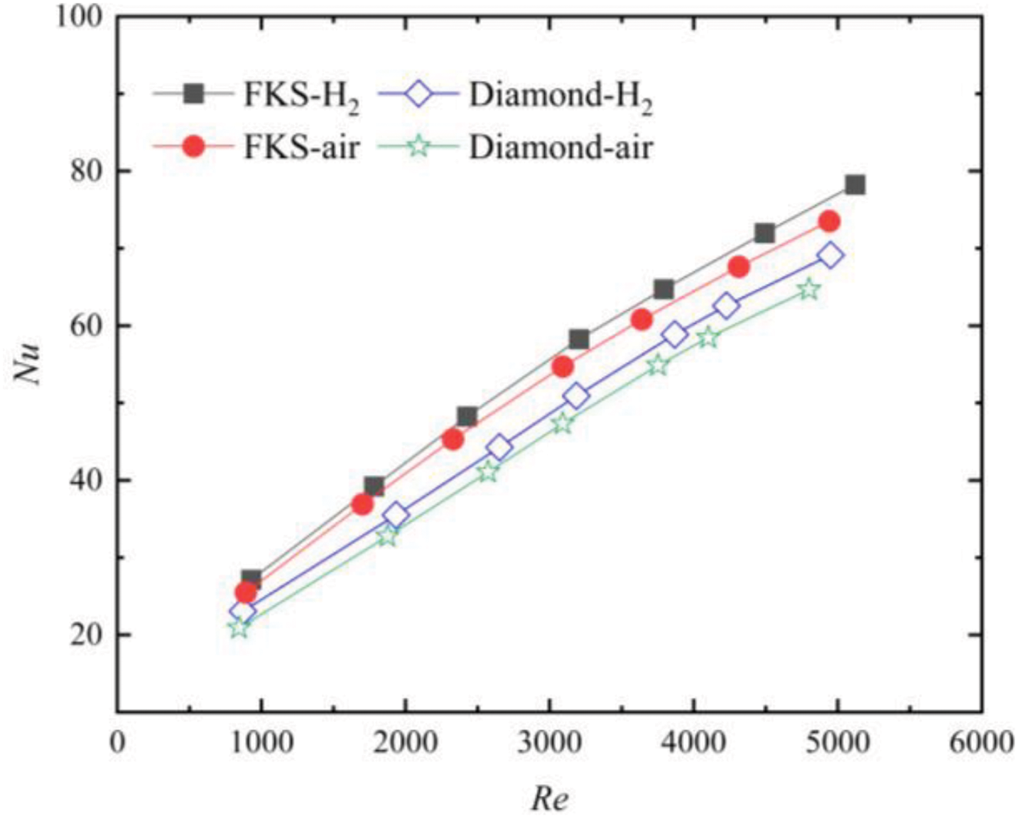
Figure 6: Average Nu distribution against Re
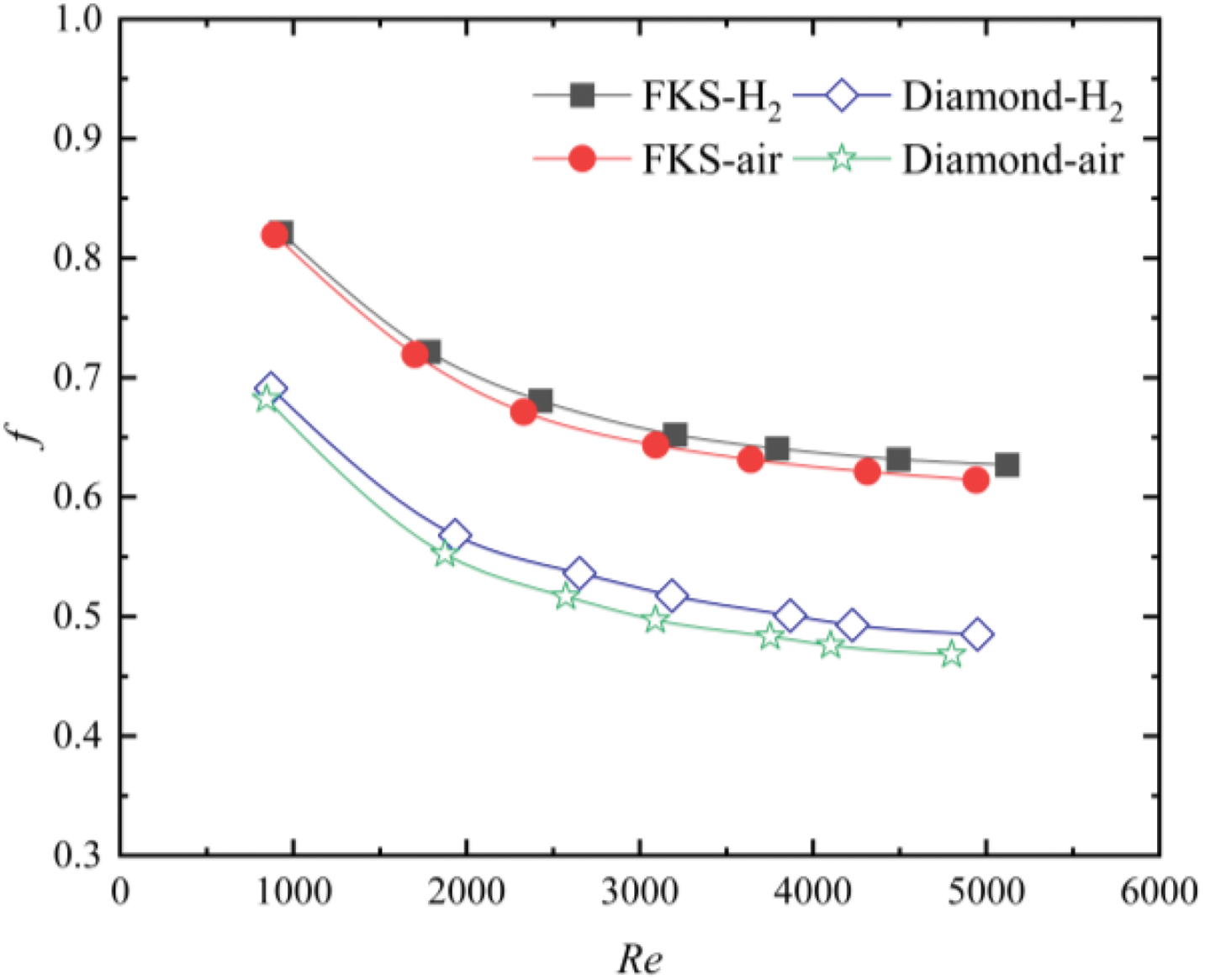
Figure 7: Average Fanning friction factor (f) distribution against Re
TPMS are an innovative concept in the field of heat exchange technology, particularly in the design of advanced precoolers. These structures hold significant promise and are expected to play a crucial role in the aerospace industry, especially in high-performance aerospace applications. The integration of precooling systems can effectively reduce the intake temperature of the engine, which in turn enhances the thermal conditions for sensitive engine components. By managing the temperature of the incoming air, these systems mitigate the adverse effects of high-speed stagnation heat, which is a common challenge in supersonic and hypersonic flight regimes. This is particularly important for hypersonic vehicles, where the extreme aerodynamic heating can damage the engine or other critical components. Moreover, by lowering the intake temperature, precooling technologies help to expand the operational range of hypersonic vehicles, allowing them to cruise for longer durations at higher speeds.
In addition to improving the thermal environment, precooling systems also have the benefit of increasing the intake flow rate. A higher intake flow leads to a more efficient combustion process within the engine, which consequently enhances the engine’s overall thrust generation. The higher thrust is a direct result of the greater amount of heat energy being captured and utilized during the combustion process, ultimately contributing to the vehicle’s performance. As a result, the implementation of TPMS-based precooling systems could offer a substantial advantage in the development of next-generation aerospace vehicles, particularly in missions requiring hypersonic speeds and sustained high-altitude flight.
This version not only expands on the technical details but also provides a deeper context for the applications and significance of TPMS structures in the aerospace sector.
This study uses numerical simulation methods to investigate two TPMS structures, FKS and Diamond, exploring the flow-enhanced HT mechanisms within both structures. Additionally, TH performance analysis is conducted for both structures as HX.
1. The curvature of the flow channels inside FKS continuously changes, causing variations in flow velocity and direction, which generate complex, swirling flow. Portions of the fluid with relatively higher velocities shear against the FKS surface, enhancing HT in the regions where the fluid collides with the walls.
2. Fluid within the Diamond channels converges at the junctions, after which it is distributed into multiple channels. During the flow process, the fluid is repeatedly redistributed and converged, enhancing fluid disturbance. Due to the reduction in the cross-sectional area of the fluid channels at the junctions, the fluid velocity increases, and a portion of the fluid shears against the surface at relatively higher speeds, thereby enhancing HT in this region.
3. Under the same Re number conditions, FKS exhibits a better Nu number distribution, with its Nu being 13.2%–17.6% higher than that of Diamond. However, the friction factor of FKS is approximately 18.8%–29.3% higher than Diamond.
Acknowledgement: The authors would like to sincerely thank Luoyang Institute of Science and Technology, Henan Key Laboratory of Green Building Materials Manufacturing and Intelligent Equipment, Xi’an Special Equipment Inspection Institute, Shandong University and Xi’an University of Architecture and Technology for providing laboratory facilities support and financial support. The scientific calculations in this paper have been done on the HPC Cloud Platform of Shandong University.
Funding Statement: This work was supported by the Natural Science Basic Research Program of Shaanxi (Program No. 2024JC-YBMS-449) and Project ZR2022QE233 supported by Shandong Provincial Natural Science Foundation.
Author Contributions: The authors confirm contribution to the paper as follows: funding acquisition, conceptualization, Cheng Bi; writing—original draft, data curation, Nan Li; methodology, Miao Wang; review & editing, Jingwen Zhao; conceptualization, methodology, writing—review & editing, Kechun Sun; investigation, Mu Du; writing—review & editing, Ersheng You; draft manuscript preparation: Mingyang Yang. All authors reviewed the results and approved the final version of the manuscript.
Availability of Data and Materials: Data can be provided on request.
Ethics Approval: Not applicable.
Conflicts of Interest: The authors declare no conflicts of interest to report regarding the present study.
References
1. Wang ZG, Wang Y, Zhang JQ, Zhang BC. Overview of the key technologies of combined cycle engine precooling systems and the advanced applications of micro-channel heat transfer. Aerosp Sci Technol. 2014;39:31–9. doi:10.1016/j.ast.2014.08.008. [Google Scholar] [CrossRef]
2. Zhang MZ, Li P, Chen ZK. Challenge and perspective of combined cycle propulsion system. J Rocket Propulsion. 2009;35(1):1–8. [Google Scholar]
3. Scott T, Riggins D, Christensen K. Thermodynamic analysis of the transposed-cycle. In: 37th Joint Propulsion Conference and Exhibit: AIAA; Salt Lake City, UT, USA; 2001. [Google Scholar]
4. Heiser WH, Pratt DT. Hypersonic airbreathing propulsion. Washington, DC, USA: AIAA; 1994. [Google Scholar]
5. Murray JJ, Guha A, Bond A. Overview of the development of heat exchangers for use in air-breathing propulsion pre-coolers. Acta Astronaut. 1997;41(11):723–9. doi:10.1016/S0094-5765(97)00199-9. [Google Scholar] [CrossRef]
6. Murray JJ, Hempsell CM, Bond A. An experimental precooled for airbreathing rocket engines. J Br Interplanet Soc. 2001;54:199–209. [Google Scholar]
7. Zou ZP, Liu HX, Tang HL, Wan M, Chen XL. Precooling technology study of hypersonic aeroengine. Acta Aeronaut Et Astronaut Sin. 2015;36:2544–62. [Google Scholar]
8. Min R, Wang ZH, Yang HN, Bao RQ, Zhang NJ. Heat transfer characterization of waste heat recovery heat exchanger based on flexible hybrid triply periodic minimal surfaces (TPMS). Int Commun Heat Mass Transf. 2024;157(8):107760. doi:10.1016/j.icheatmasstransfer.2024.107760. [Google Scholar] [CrossRef]
9. Huang WS, Ning HY, Li N, Tang GH, Ma Y, Li Z, et al. Thermal-hydraulic performance of TPMS-based regenerators in combined cycle aero-engine. Appl Therm Eng. 2024;250:123510. doi:10.1016/j.applthermaleng.2024.123510. [Google Scholar] [CrossRef]
10. Xian L, Li Z, Li S, Chen L, Tao WQ. Elucidating the impact mechanism of temperature and water content on thermal conductivity of hydrated Nafion membranes by molecular dynamics simulation. Int J Heat Mass Transf. 2023;208:124034. doi:10.1016/j.ijheatmasstransfer.2023.124034. [Google Scholar] [CrossRef]
11. Chen B, Eddaoudi M, Hyde ST, O’Keeffe M, Yaghi OM. Interwoven metal-organic framework on a periodic minimal surface with extra-large pores. Science. 2001;291(5506):1021–3. doi:10.1126/science.1056598. [Google Scholar] [PubMed] [CrossRef]
12. Shen M, Qin W, Xing B, Zhao W, Gao S, Sun Y, et al. Mechanical properties of 3D printed ceramic cellular materials with triply periodic minimal surface architectures. J Eur Ceram Soc. 2021;41(2):1481–9. doi:10.1016/j.jeurceramsoc.2020.09.062. [Google Scholar] [CrossRef]
13. Al-Ketan O, Lee DW, Rowshan R, Al-Rub RKA. Functionally graded and multi-morphology sheet TPMS lattices: design, manufacturing, and mechanical properties. J Mech Behav Biomed Mater. 2020;102(10):103520. doi:10.1016/j.jmbbm.2019.103520. [Google Scholar] [PubMed] [CrossRef]
14. Feng J, Fu J, Yao X, He Y. Triply periodic minimal surface (TPMS) porous structures: from multi-scale design, precise additive manufacturing to multidisciplinary applications. Int J Extreme Manuf. 2022;4(2):022001. doi:10.1088/2631-7990/ac5be6. [Google Scholar] [CrossRef]
15. Qureshi ZA, Elnajjar E, Al-Ketan O, Al-Rub RA, Al-Omari SB. Heat transfer performance of a finned metal foam-phase change material (FMF-PCM) system incorporating triply periodic minimal surfaces (TPMS). Int J Heat Mass Transf. 2021;170(3):121001. doi:10.1016/j.ijheatmasstransfer.2021.121001. [Google Scholar] [CrossRef]
16. Qureshi ZA, Al Omari SAB, Elnajjar E, Mahmoud F, Al-Ketan O, Al-Rub RA. Thermal characterization of 3D-printed lattices based on triply periodic minimal surfaces embedded with organic phase change material. Case Stud Therm Eng. 2021;27(3):101315. doi:10.1016/j.csite.2021.101315. [Google Scholar] [CrossRef]
17. Qureshi ZA, Al-Omari SAB, Elnajjar E, Al-Ketan O, Al-Rub RA. On the effect of porosity and functional grading of 3D printable triply periodic minimal surface (TPMS) based architected lattices embedded with a phase change material. Int J Heat Mass Transf. 2022;183(31):122111. doi:10.1016/j.ijheatmasstransfer.2021.122111. [Google Scholar] [CrossRef]
18. Qureshi ZA, Al-Omari SAB, Elnajjar E, Al-Ketan O, Al-Rub RA. Nature-inspired triply periodic minimal surface-based structures in sheet and solid configurations for performance enhancement of a low-thermal-conductivity phase-change material for latent-heat thermal-energy-storage applications. Int J Therm Sci. 2022;173(10):107361. doi:10.1016/j.ijthermalsci.2021.107361. [Google Scholar] [CrossRef]
19. Fan Z, Gao R, Liu S. Thermal conductivity enhancement and thermal saturation elimination designs of battery thermal management system for phase change materials based on triply periodic minimal surface. Energy. 2022;259(4):125091. doi:10.1016/j.energy.2022.125091. [Google Scholar] [CrossRef]
20. Fan Z, Gao R, Liu S. A novel battery thermal management system based on P type triply periodic minimal surface. Int J Heat Mass Transf. 2022;194(13):123090. doi:10.1016/j.ijheatmasstransfer.2022.123090. [Google Scholar] [CrossRef]
21. Kaur I, Singh P. Flow and thermal transport characteristics of Triply-Periodic Minimal Surface (TPMS)-based gyroid and Schwarz-P cellular materials. Numer Heat Transf, Part A: Appl. 2021;79(8):553–69. doi:10.1080/10407782.2021.1872260. [Google Scholar] [CrossRef]
22. Modrek M, Viswanath A, Khan KA, Ali MIH, Al-Rub RKA. An optimization case study to design additively manufacturable porous heat sinks based on triply periodic minimal surface (TPMS) lattices. Case Stud Therm Eng. 2022;36(4):102161. doi:10.1016/j.csite.2022.102161. [Google Scholar] [CrossRef]
23. Alteneiji M, Ali MIH, Khan KA, Al-Rub RKA. Heat transfer effectiveness characteristics maps for additively manufactured TPMS compact heat exchangers. Energy Storage Saving. 2022;1(3):153–61. doi:10.1016/j.enss.2022.04.005. [Google Scholar] [CrossRef]
24. Attarzadeh R, Attarzadeh-Niaki SH, Duwig C. Multi-objective optimization of TPMS-based heat exchangers for low-temperature waste heat recovery. Appl Therm Eng. 2022;212(2):118448. doi:10.1016/j.applthermaleng.2022.118448. [Google Scholar] [CrossRef]
25. Wang S, Jiang Y, Hu J, Fan X, Luo Z, Liu Y. Efficient representation and optimization of TPMS-based porous structures for 3D heat dissipation. Comput Aided Des. 2022;142(11–12):103123. doi:10.1016/j.cad.2021.103123. [Google Scholar] [CrossRef]
26. Kwasi-Effah CC, Ibhadode O, Qureshi A. Thermo-hydraulic performance characteristics of novel G-prime and FRD Triply Periodic Minimal Surface (TPMS) geometries. Int Commun Heat Mass Transf. 2024;159(8):108226. doi:10.1016/j.icheatmasstransfer.2024.108226. [Google Scholar] [CrossRef]
27. Khalil M, Ali MIH, Khan KA, Al-Rub RA. Forced convection heat transfer in heat sinks with topologies based on triply periodic minimal surfaces. Case Stud Therm Eng. 2022;38(4):102313. doi:10.1016/j.csite.2022.102313. [Google Scholar] [CrossRef]
28. Liang D, Shi C, Li W, Chen W, Chyu MK. Design, flow characteristics and performance evaluation of bioinspired heat exchangers based on triply periodic minimal surfaces. Int J Heat Mass Transf. 2023;201(4):123620. doi:10.1016/j.ijheatmasstransfer.2022.123620. [Google Scholar] [CrossRef]
29. Peng H, Gao F, Hu W. Design, modeling and characterization on triply periodic minimal surface heat exchangers with additive manufacturing. In: 2019 International Solid Freeform Fabrication Symposium; 2019; University of Texas at Austin. [Google Scholar]
30. Valentine DT, Hahn BH. Essential MATLAB for engineers and scientists. New York, NY, USA: University of Cape Town Press; 2022. [Google Scholar]
31. ANSYS SpaceClaim. 3D CAD Modeling Software. Canonsburg, PA, USA: Ansys; 2022. [Google Scholar]
32. ANSYS Fluent. ANSYS fluent theory guide 19.0. Canonsburg, PA, USA: Ansys; 2019. [Google Scholar]
33. Michielsen K, Kole JS. Photonic band gaps in materials with triply periodic surfaces and related tubular structures. Phys Rev B. 2003;68(11):115107. doi:10.1103/PhysRevB.68.115107. [Google Scholar] [CrossRef]
34. Xu H, Yu W, Zhang Y, Ma S, Wu Z, Liu X. Flow and heat transfer performance of bionic heat transfer structures with hybrid triply periodic minimal surfaces. Appl Energy. 2023;351:121847. doi:10.1016/j.apenergy.2023.121847. [Google Scholar] [CrossRef]
35. Tang W, Zhou H, Zeng Y, Yan M, Jiang C, Yang P, et al. Analysis on the convective heat transfer process and performance evaluation of Triply Periodic Minimal Surface (TPMS) based on Diamondmond, Gyroid and Iwp. Int J Heat Mass Transf. 2023;201(2):123642. doi:10.1016/j.ijheatmasstransfer.2022.123642. [Google Scholar] [CrossRef]
Cite This Article
 Copyright © 2025 The Author(s). Published by Tech Science Press.
This work is licensed under a Creative Commons Attribution 4.0 International License , which permits unrestricted use, distribution, and reproduction in any medium, provided the original work is properly cited.
 Downloads
 Citation Tools